H61M-S1 PLUS - Motherboard ASROCK - Free user manual and instructions
Find the device manual for free H61M-S1 PLUS ASROCK in PDF.

User questions about H61M-S1 PLUS ASROCK
0 question about this device. Answer the ones you know or ask your own.
Ask a new question about this device
Download the instructions for your Motherboard in PDF format for free! Find your manual H61M-S1 PLUS - ASROCK and take your electronic device back in hand. On this page are published all the documents necessary for the use of your device. H61M-S1 PLUS by ASROCK.
USER MANUAL H61M-S1 PLUS ASROCK
Published January 2014
Copyright©2014 ASRock INC. All rights reserved.
Copyright Notice:
No part of this manual may be reproduced, transcribed, transmitted, or translated in any language, in any form or by any means, except duplication of documentation by the purchaser for backup purpose, without written consent of ASRock Inc.
Products and corporate names appearing in this manual may or may not be registered trademarks or copyrights of their respective companies, and are used only for identification or explanation and to the owners' benefit, without intent to infringe.
Disclaimer:
Specifications and information contained in this manual are furnished for informational use only and subject to change without notice, and should not be constructed as a commitment by ASRock. ASRock assumes no responsibility for any errors or omissions that may appear in this manual.
With respect to the contents of this manual, ASRock does not provide warranty of any kind, either expressed or implied, including but not limited to the implied warranties or conditions of merchantability or fitness for a particular purpose.
In no event shall ASRock, its directors, officers, employees, or agents be liable for any indirect, special, incidental, or consequential damages (including damages for loss of profits, loss of business, loss of data, interruption of business and the like), even if ASRock has been advised of the possibility of such damages arising from any defect or error in the manual or product.

This device complies with Part 15 of the FCC Rules. Operation is subject to the following two conditions:
(1) this device may not cause harmful interference, and
(2) this device must accept any interference received, including interference that may cause undesired operation.
CALIFORNIA, USA ONLY
The Lithium battery adopted on this motherboard contains Perchlorate, a toxic substance controlled in Perchlorate Best Management Practices (BMP) regulations passed by the California Legislature. When you discard the Lithium battery in California, USA, please follow the related regulations in advance.
"Perchlorate Material-special handling may apply, see www.dtsc.ca.gov/hazardouswaste/perchlorate"
The terms HDMI ^™ and HDMI High-Definition Multimedia Interface, and the HDMI logo are trademarks or registered trademarks of HDMI Licensing LLC in the United States and other countries.
Contents
1 Introduction ...... 5
1.1 Package Contents .... 5
1.2 Specifications 6
1.3 Unique Features 9
1.4 Motherboard Layout 13
1.5 I/O Panel 14
2 Installation 16
2.1 Screw Holes 16
2.2 Pre-installation Precautions 16
2.3 CPU Installation 17
2.4 Installation of Heatsink and CPU fan 19
2.5 Installation of Memory Modules (DIMM) 20
2.6 Expansion Slots (PCI Express Slots).... 21
2.7 Jumpers Setup 22
2.8 Onboard Headers and Connectors 23
2.9 Driver Installation Guide 28
3 UEFI SETUP UTILITY 29
3.1 Introduction 29
3.1.1 UEFI Menu Bar 29
3.1.2 Navigation Keys 30
3.2 Main Screen 30
3.3 OC Tweaker Screen 31
3.4 Advanced Screen 35
3.4.1 CPU Configuration 36
3.4.2 North Bridge Configuration.... 38
3.4.3 South Bridge Configuration 39
3.4.4 Storage Configuration 40
3.4.5 Intel(R) Rapid Start Technology 41
3.4.6 Intel(R) Smart Connect Technology 42
3.4.7 Super IO Configuration 43
3.4.8 ACPI Configuration.... 44
3.4.9 USB Configuration 45
3.5 Tool 46
3.6 Hardware Health Event Monitoring Screen 48
3.7 Boot Screen 49
3.8 Security Screen 51
3.9 Exit Screen 52
4 Software Support 53
4.1 Install Operating System 53
4.2 Support CD Information 53
4.2.1 Running Support CD 53
4.2.2 Drivers Menu 53
4.2.3 Utilities Menu.... 53
4.2.4 Contact Information 53
Chapter 1: Introduction
Thank you for purchasing ASRock H61M-S1 PLUS motherboard, a reliable motherboard produced under ASRock's consistently stringent quality control. It delivers excellent performance with robust design conforming to ASRock's commitment to quality and endurance.
In this manual, chapter 1 and 2 contain introduction of the motherboard and step-by-step guide to the hardware installation. Chapter 3 and 4 contain the configuration guide to BIOS setup and information of the Support CD.

Because the motherboard specifications and the BIOS software might be updated, the content of this manual will be subject to change without notice. In case any modifications of this manual occur, the updated version will be available on ASRock website without further notice. You may find the latest VGA cards and CPU support lists on ASRock website as well. ASRock website http://www.asrock.com
If you require technical support related to this motherboard, please visit our website for specific information about the model you are using.
www.asrock.com/support/index.asp
1.1 Package Contents
ASRock H61M-S1 PLUS Motherboard (Micro ATX Form Factor)
ASRock H61M-S1 PLUS Quick Installation Guide
ASRock H61M-S1 PLUS Support CD
2 x Serial ATA (SATA) Data Cables (Optional)
1 x Mouse Pad
1 x I/O Panel Shield

ASRock Reminds You...
To get better performance in Windows ^® 8.1 / 8.1 64-bit / 8 / 8 64-bit / 7 / 7 64-bit / Vista ^TM / Vista ^TM 64-bit, it is recommended to set the BIOS option in Storage Configuration to AHCI mode.
1.2 Specifications
| Platform - Micro ATX Form Factor- All Solid Capacitordesign | |
| CPU - Supports 3Xeon-Supports Intel-Supports K-Series | ^rd and 2^nd Generation Intel ^ Core ^TM i7 / i5 / i3 / ^ / Pentium ^ / Celeron ^ in LGA1155 Package ^ Turbo Boost 2.0 Technologyunlocked CPU |
| Chipset - Intel-Supports IntelTechnology | ^ H61 ^ Rapid Start Technology and Smart Connect |
| Memory - Dual Channel DDR3 Memory Technology- 2 x DDR3 DIMM slots-Supports DDR3 1600/1333/1066 non-ECC, un-bufferedmemory (DDR3 1600 with Intel ^ Ivy Bridge CPU, DDR31333 with Intel ^ Sandy Bridge CPU)- Max. capacity of system memory: 16GB (seeCAUTION 1)- Supports IntelIntel ^ Extreme Memory Profile (XMP) 1.3 / 1.2 with ^ Ivy Bridge CPU | |
| Expansion Slot - 1 x PCI Express 3.0 x16 slot (blue @ x16 mode)* PCIE 3.0 is only supported with Intel ^ Ivy Bridge CPU. WithIntel ^ Sandy Bridge CPU, it only supports PCIE 2.0.- 1 x PCI Express 2.0 x1 slot | |
| Graphics * Intelbe supported only with processors which are GPUintegrated.- Supports IntelSync Video 2.0, IntelTechnology, Intelwith Intel-Supports IntelSync Video, IntelTechnology, IntelVector Extensions (AVX) with Intel-Pixel Shader 5.0, DirectX 11 with IntelPixel Shader 4.1, DirectX 10.1 with IntelCPU.- Max. shared memory 1760MB with IntelMax. shared memory 1759MB with IntelCPU. | ^ HD Graphics Built-in Visuals and the VGA outputs canwith processors which are GPU ^ HD Graphics Built-in Visuals: Intel ^ Quick ^ InTru ^TM 3D, Intel ^ Clear Video HD ^ Insider ^TM , Intel ^ HD Graphics 2500/4000 ^ Ivy Bridge CPU ^ HD Graphics Built-in Visuals: Intel ^ Quick ^ InTru ^TM 3D, Intel ^ Clear Video HD ^ HD Graphics 2000/3000, Intel ^ Advanced ^ Sandy Bridge CPU ^ Ivy Bridge CPU. ^ Sandy BridgeCPU. ^ Ivy Bridge CPU. ^ Sandy BridgeCPU. ^ Sandy BridgeCPU. ^ Sandy BridgeCPU. ^ Sandy BridgeCPU. ^ Sandy BridgeCPU. ^ Sandy BridgeCPU. ^ Sandy BridgeCPU. ^ Sandy BridgeCPU. ^ Sandy BridgeCPU. ^ Sandy BridgeCPU. ^ Sandy BridgeCPU. ^ Sandy BridgeCPU. ^ Sandy BridgeCPU. ^ Sandy BridgeCPU. ^ Sandy BridgeCPU. ^ Sandy BridgeCPU. ^ Sandy BridgeCPU. ^ Sandy BridgeCPU. ^ Sandy Bridge CPU ^ Sandy Bridge CPU ^ Sandy Bridge CPU ^ Sandy Bridge CPU ^ Sandy Bridge CPU ^ Sandy Bridge CPU ^ Sandy Bridge CPU ^ Sandy Bridge CPU ^ Sandy Bridge CPU ^ Sandy Bridge CPU ^ Sandy Bridge CPU ^ Sandy Bridge CPU ^ Sandy Bridge CPU ^ Sandy Bridge CPU ^ Sandy Bridge CPU ^ Sandy Bridge CPU ^ Sandy Bridge CPU ^ Sandy Bridge CPU ^ Sandy Bridge CPU ^ Sandy Bridge CPU ^ Sandy Bridge CPU ^ Sandy Bridge CPU ^ Sandy Bridge CPU ^ Sandy Bridge CPU ^ Sandy Bridge CPU ^ Sandy Bridge CPU ^ Sandy Bridge CPU ^ Sandy Bridge CPU ^ ) Sandy Bridge CPU ^ Sandy Bridge CPU ^ Sandy Bridge CPU ^ Sandy Bridge CPU ^ Sandy Bridge CPU ^ Sandy Bridge CPU ^ Sandy Bridge CPU ^ Sandy Bridge CPU ^ Sandy Bridge CPU ^ , Sandy Bridge CPU ^ , Sandy Bridge CPU ^ , Sandy Bridge CPU ^ , Sandy Bridge CPU ^ , Sandy Bridge CPU ^ , Sandy Bridge CPU ^ , Sandy Bridge CPU ^ , Sandy Bridge CPU ^ , Sandy bridge CPU ^ , Sandy bridge CPU ^ , Sandy bridge CPU ^ , Sandy bridge CPU ^ , Sandy bridge CPU ^ , Sandy bridge CPU ^ , Sandy bridge CPU ^ , Sandy bridge CPU ^ , Sandy bridge CPU ^ , Sandy bridge CPU ^ , Sandy bridge CPU ^ , Sandy bridge CPU ^ , Sandy bridge CPU ^ , Sandy bridge CPU ^ , Sandy bridge CPU ^ , Sandy bridge CPU ^ , Sandy bridge CPU ^ Sandy bridge CPU ^ , Sandy bridge CPU ^ , Sandy bridge CPU ^ , Sandy bridge CPU ^ , Sandy bridge CPU ^ , Sandy bridge CPU ^ , Sandy bridge CPU ^ , Sandy bridge CPU ^ , Sandy Bridge CPU ^ , Sandy Bridge CPU ^ , Sandy Bridge CPU ^ , Sandy Bridge CPU ^ , Sandy Bridge CPU ^ , Sandy Bridge CPU ^ , Sandy Bridge CPU ^ , Sandy Bridge CPU ^ , Sandy Bridge CPU ^ , Sandy Bridge CPU ^ , Sandy Bridge CPU ^ , Sandy Bridge CPU ^ , Sandy Bridge CPU ^ , Sandy Bridge CPU ^ , Sandy Bridge CPU ^ , Sandy Bridge CPU ^ ^ Sandy Bridge CPU ^ Sandy Bridge CPU ^ Sandy Bridge CPU ^ Sandy Bridge CPU ^ Sandy Bridge CPU ^ Sandy Bridge CPU ^ Sandy Bridge CPU ^ ^ Sandy Bridge CPU ^ Sandy Bridge CPU ^ Sandy Bridge CPU ^ Sandy Bridge CPU ^ ^ Sandy Bridge CPU ^ Sandy Bridge CPU ^ ^ Sandy Bridge CPU ^ Sandy Bridge CPU ^ ^ Sandy Bridge CPU ^ Sandy Bridge CPU ^ ^ Sandy BridgeCPU ^ Sandy Bridge CPU ^ ^ Sandy Bridge CPU ^ Sandy Bridge CPU ^ ^ Sandy Bridge CPU ^ ^ Sandy Bridge CPU ^ ^ Sandy Bridge CPU ^ ^ Sandy Bridge CPU ^ ^ Sandy Bridge CPU ^ ^ Sandy Bridge CPU ^ ^ Sandy Bridge CPU ^ ^ Sandy Bridge CPU ^ ^ Sandy Bridge CPU ^ ^ Sandy Bridge CPU ^ ^ , Sandy Bridge CPU ^ ^ Sandy Bridge CPU ^ ^ Sandy Bridge CPU ^ ^ Sandy Bridge CPU ^ ^ Sandy Bridge CPU ^ ^ Sandy BridgeCPU ^ ^ Sandy Bridge CPU ^ ^ Sandy Bridge CPU ^ ^ Sandy Bridge CPU ^ ^ Sandy Bridge CPU ^ ^ Sandy Bridge CPU ^ Eigenvalue ^ ^ ^ ^ ^ ^ ^ ^ ^ ^ ^ ^ ^ 1760MB with IntelMax. shared memory 1759MB with IntelCPU. |
| - Dual Graphics Output: support HDMI and D-Sub ports by independent display controllers- Supports HDMI Technology with max. resolution up to 1920x1200 @ 60Hz- Supports D-Sub with max. resolution up to 2048x1536 @ 75Hz- Supports Auto Lip Sync, Deep Color (12bpc), xvYCC and HBR (High Bit Rate Audio) with HDMI (Compliant HDMI monitor is required)- Supports HDCP function with HDMI port- Supports Full HD 1080p Blu-ray (BD) playback with HDMI port | |
| Audio - 5.1 CH HD Audio (Realtek ALC662 Audio Codec) | |
| LAN - PCIE x1 Gigabit LAN 10/100/1000 Mb/s- Realtek RTL8111E- Supports Wake-On-LAN- Supports LAN Cable Detection- Supports Energy Efficient Ethernet 802.3az- Supports PXE | |
| Rear Panel I/O I/O Panel- 1 x PS/2 Mouse Port- 1 x PS/2 Keyboard Port- 1 x Serial Port: COM1- 1 x Parallel Port (ECP/EPP support)- 1 x D-Sub Port- 1 x HDMI Port- 4 x USB 2.0 Ports- 1 x RJ-45 LAN Port with LED (ACT/LINK LED and SPEED LED)- HD Audio Jack: Line in/Front Speaker/Microphone | |
| Storage - 4 x SATA2 3.0 Gb/s connectors, support NCQ, AHCI and Hot Plug functions | |
| Connector - 1 x IR header- 1 x Power LED header- 1 x Chassis Intrusion header- 1 x LPC/TPM header- 1 x CPU Fan connectors (4-pin)- 1 x Chassis Fan connector (4-pin)- 1 x 24 pin ATX power connector- 1 x 4 pin 12V power connector- 1 x Front panel audio connector | |
| - 1 x SPDIF Out connector- 2 x USB 2.0 headers (support 4 USB 2.0 ports) | |
| BIOS Feature - 32Mb AMI UEFI Legal BIOS with GUI support- Supports “Plug and Play”- ACPI 1.1 Compliance Wake Up Events- Supports jumperfree- SMBIOS 2.3.1 Support | |
| Support CD - Drivers, Utilities, AntiVirus Software (Trial Version), GoogleChrome Browser and Toolbar, Start8 (30 days trial) | |
| Hardware - CPU/Chassis Temperature SensingMonitor - CPU/Chassis Fan Tachometer- CPU Quiet Fan (Allow Chassis Fan Speed Auto-Adjust byCPU Temperature)- CPU/Chassis Fan Multi-Speed Control- CASE OPEN detection- Voltage Monitoring: +12V, +5V, +3.3V, CPU Vcore | |
| OS - Microsoft® Windows® 8.1 32-bit / 8.1 64-bit / 8 32-bit / 864-bit / 7 32-bit / 7 64-bit / VistaTM 32-bit / VistaTM 64-bit / XP32-bit / XP 64-bit (Windows® 8.1 is supported with Intel® IvyBridge CPU for onboard VGA.) | |
| Certifications - FCC, CE, WHQL | |
* For detailed product information, please visit our website: http://www.asrock.com
WARNING
Please realize that there is a certain risk involved with overclocking, including adjusting the setting in the BIOS, applying Untied Overclocking Technology, or using third-party overclocking tools. Overclocking may affect your system's stability, or even cause damage to the components and devices of your system. It should be done at your own risk and expense. We are not responsible for possible damage caused by overclocking.
CAUTION!
- Due to the operating system limitation, the actual memory size may be less than 4GB for the reservation for system usage under Windows ^® 8.1 / 8 / 7 / Vista ^TM / XP. For Windows ^® OS with 64-bit CPU, there is no such limitation. You can use ASRock XFast RAM to utilize the memory that Windows ^® cannot use.
1.3 Unique Features
ASRock Extreme Tuning Utility (AXTU)
ASRock Extreme Tuning Utility (AXTU) is an all-in-one tool to ne-tune different system functions in a user-friendly interface, which includes Hardware Monitor, Fan Control and XFast RAM. In Hardware Monitor, it shows the major readings of your system. In Fan Control, it shows the fan speed and temperature for you to adjust. In XFast RAM, it fully utilizes the memory space that cannot be used under Windows® OS 32-bit CPU.
ASRock Instant Boot
ASRock Instant Boot allows you to turn on your PC in just a few seconds, provides a much more efficient way to save energy, time, money, and improves system running speed for your system. It leverages the S3 and S4 ACPI features which normally enable the Sleep/Standby and Hibernation modes in Windows ^® to shorten boot up time. By calling S3 and S4 at specific timing during the shutdown and startup process, Instant Boot allows you to enter your Windows ^® desktop in a few seconds.
ASRock Instant Flash
ASRock Instant Flash is a BIOS flash utility embedded in Flash ROM. This convenient BIOS update tool allows you to update system BIOS without entering operating systems first like MS-DOS or Windows®. With this utility, you can press the
ASRock APP Charger
If you desire a faster, less restricted way of charging your Apple devices, such as iPhone/iPad/iPod Touch, ASRock has prepared a wonderful solution for you - ASRock APP Charger. Simply install the APP Charger driver, it makes your iPhone charge much quickly from your computer and up to 40% faster than before. ASRock APP Charger allows you to quickly charge many Apple devices simultaneously and even supports continuous charging when your PC enters into Standby mode (S1), Suspend to RAM (S3), hibernation mode (S4) or power off (S5). With APP Charger driver installed, you can easily enjoy the marvelous charging experience.
ASRock XFast LAN
ASRock XFast LAN provides a faster internet access, which includes the benefits listed below. LAN Application Prioritization: You can configure your application's priority ideally and/or add new programs. Lower Latency in Game: After setting online game's priority higher, it can lower the latency in games. Traffic Shaping: You can watch Youtube HD videos and download simultaneously. Real-Time Analysis of Your Data: With the status window, you can easily recognize which data streams you are transferring currently.
ASRock XFast RAM
ASRock XFast RAM is a new function that is included into AS-Rock Extreme Tuning Utility (AXTU). It fully utilizes the memory space that cannot be used under Windows® OS 32-bit CPU. ASRock XFast RAM shortens the loading time of previously visited websites, making web surfing faster than ever. And it also boosts the speed of Adobe Photoshop 5 times faster. Another advantage of ASRock XFast RAM is that it reduces the frequency of accessing your SSDs or HDDs in order to extend their lifespan.
ASRock Crashless BIOS
ASRock Crashless BIOS allows users to update their BIOS without fear of failing. If power loss occurs during the BIOS update process, ASRock Crashless BIOS will automatically finish the BIOS update procedure after regaining power. Please note that BIOS files need to be placed in the root directory of your USB disk. Only USB2.0 ports support this feature.
ASRock OMG (Online Management Guard)
Administrators are able to establish an internet curfew or restrict internet access at specified times via OMG. You may schedule the starting and ending hours of internet access granted to other users. In order to prevent users from bypassing OMG, guest accounts without permission to modify the system time are required.
ASRock Internet Flash
ASRock Internet Flash searches for available UEFI firmware updates from our servers. In other words, the system can auto-detect the latest UEFI from our servers and flash them without entering Windows® OS.
ASRock Dehumidifier Function
Users may prevent motherboard damages due to dampness by enabling “Dehumidifier Function”. When enabling Dehumidifier Function, the computer will power on automatically to dehumidify the system after entering S4/S5 state.
ASRock Fast Boot
With ASRock's exclusive Fast Boot technology, it takes less than 1.5 seconds to logon to Windows ^ 8.1 / 8 from a cold boot. No more waiting! The speedy boot will completely change your user experience and behavior.
ASRock Restart to UEFI
Windows ^® 8.1 / 8 brings the ultimate boot up experience. The lightning boot up speed makes it hard to access the UEFI setup. ASRock Restart to UEFI technology is designed for those requiring frequent UEFI access. It allows users to easily enter the UEFI automatically when turning on the PC next time. Just simply enable this function; the PC will be assured to access the UEFI directly in the very beginning.
ASRock Combo Cooler Option (C.C.O.)
Combo Cooler Option (C.C.O.) provides the flexible option to adopt three different CPU cooler types, Socket LGA 775, LGA 1155 and LGA 1156. Please be noticed that not all the 775 and 1156 CPU Fan can be used.
ASRock Good Night LED
ASRock Good Night LED technology can offer you a better environment by extinguishing the unessential LED. By enabling Good Night LED in BIOS, the Power / HDD / LAN LED will be switched off when system is on. Not only this, Good night LED will automatically switch off Power and Keyboard LED when the system enters into Standby / Hibernation mode as well.
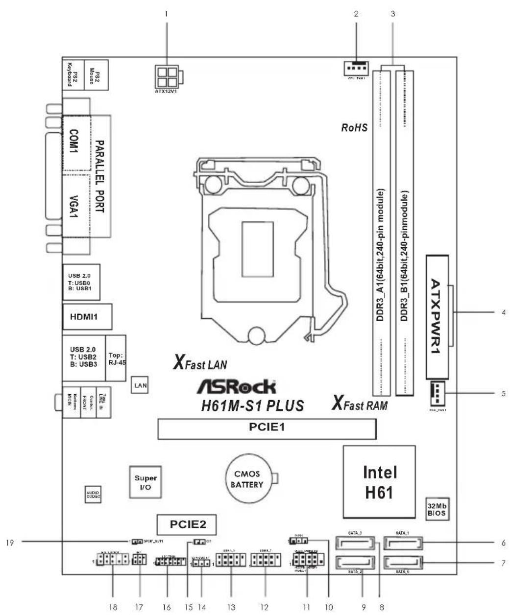
1.4 Motherboard Layout
text_image
XFast LAN ASRock® H61M-S1 PLUS XFast RAM PCIE1 Super I/O CMOS BATTERY Intel H61 PCIE2 ATX12V1 ATX PWR1 DDR3_A1(64bit,240-pin module) DDR3_B1(64bit,240-pinmodule) RoHS COM1 PARALLEL PORT VGA1 USB 2.0 T: USB0 B: USB1 HDMI1 USB 2.0 T: USB2 B: USB3 Top: RJ-45 LAN COM1 FROXT COM1 LINE IN NICOM 32Mb BIOS 32MB BIOS 8 9 8 7 6 5 4 31 ATX 12V Power Connector (ATX12V1) 10 Power LED Header (PLED1)
2 CPU Fan Connector (CPU_FAN1) 11 System Panel Header (PANEL1)
3 2 x 240-pin DDR3 DIMM Slots 12 USB 2.0 Header (USB6_7)
(Dual Channel: DDR3_A1, DDR3_B1) 13 USB 2.0 Header (USB4_5)
4 ATX Power Connector (ATXPWR1) 14 Clear CMOS Jumper (CLRCMOS1)
5 Chassis Fan Connector (CHA_FAN1) 15 Chassis Intrusion Header (CI1)
6 SATA2 Connector (SATA_1) 16 LPC / TPM Header (LPC/TPM1)
7 SATA2 Connector (SATA_0) 17 Infrared Module Header (IR1)
8 SATA2 Connector (SATA_3) 18 Front Panel Audio Header (HD_AUDIO1)
9 SATA2 Connector (SATA_2) 19 SPDIF Out Connector (SPDIF_OUT1)
1.5 I/O Panel

text_image
1 2 3 4 5 6 11129 10 8 71 PS/2 Mouse Port (Green) 7 USB 2.0 Ports (USB23)
2 Parallel Port (LPT1) 8 HDMI Port (HDMI1)
3 LAN RJ-45 Port* 9 USB 2.0 Ports (USB01)
4 Line In (Light Blue) 10 D-Sub Port (VGA1)
5 Front Speaker (Lime) 11 Serial Port (COM1)
6 Microphone (Pink) 12 PS/2 Keyboard Port (Purple)
* There are two LED next to the LAN port. Please refer to the table below for the LAN port LED indications.
LAN Port LED Indications
Activity/Link LED
| Status | Description |
| Off | No Link |
| Blinking | Data Activity |
| On | Link |
SPEED LED
| Status | Description |
| Off | 10Mbps connection |
| Orange | 100Mbps connection |
| Green | 1Gbps connection |
ACT/LINK SPEED

LAN Port
To enable Multi-Streaming function, you need to connect a front panel audio cable to the front panel audio header. Please refer to below steps for the software setting of Multi-Streaming.
For Windows ^® XP:
After restarting your computer, you will find "Mixer" tool on your system. Please select "Mixer ToolBox", click "Enable playback multi-streaming", and click "ok". Choose "2CH" or

"4CH" and then you are allowed to select "Realtek HDA Primary output" to use Rear Speaker and Front Speaker, or select "Realtek HDA Audio 2nd output" to use front panel audio. Then reboot your system.
For Windows ^® 8.1 / 8 / 7 / Vista ^TM .
After restarting your computer, please double-click "Realtek HD Audio Manager" on the system tray. Set "Speaker Configuration" to "Quadraphonic" or "Stereo". Click "Device advanced settings", choose "Make front and rear output devices playbacks two different audio streams simultaneously", and click "ok". Then reboot your system.
Chapter 2: Installation
This is a Micro ATX form factor motherboard. Before you install the motherboard, study the configuration of your chassis to ensure that the motherboard fits into it.

Make sure to unplug the power cord before installing or removing the
motherboard. Failure to do so may cause physical injuries to you and damages to motherboard components.
2.1 Screw Holes
Place screws into the holes indicated by circles to secure the motherboard to the chassis.

Do not over-tighten the screws! Doing so may damage the motherboard.
2.2 Pre-installation Precautions
Take note of the following precautions before you install motherboard components or change any motherboard settings.
- Unplug the power cord from the wall socket before touching any component.
- To avoid damaging the motherboard components due to static electricity, NEVER place your motherboard directly on the carpet or the like. Also remember to use a grounded wrist strap or touch a safety grounded object before you handle components.
- Hold components by the edges and do not touch the ICs.
- Whenever you uninstall any component, place it on a grounded antistatic pad or in the bag that comes with the component.

Before you install or remove any component, ensure that the power is tched off or the power cord is detached from the power supply.
Failure to do so may cause severe damage to the motherboard, peripherals, and/or components.
2.3 CPU Installation
For the installation of Intel 1155-Pin CPU, please follow the steps below.
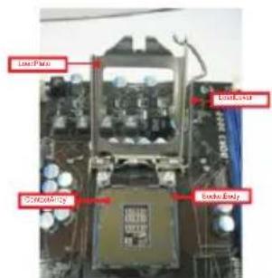
text_image
Load Parts Load Drive 320060M109 Bendu Body1155-Pin Socket Overview

Before you insert the 1155-Pin CPU into the socket, please check if the CPU surface is unclean or if there is any bent pin on the socket. Do not force to insert the CPU into the socket if above situation is found. Otherwise, the CPU will be seriously damaged.
Step 1. Open the socket:
Step 1-1. Disengaging the lever by depressing down and out on the hook to clear retention tab.

natural_image
Close-up of a computer motherboard with a CPU socket and a finger inserted (no visible text or symbols)Step 1-2. Rotate the load lever to fully open position at approximately 135 degrees.

natural_image
Close-up of a computer motherboard with CPU socket and motherboard (no visible text or symbols)Step 1-3. Rotate the load plate to fully open position at approximately 100 degrees.
Step 2. Remove PnP Cap:
Step 2-1. Attach your index finger to the upper edge of the PnP Cap.
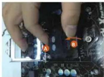
natural_image
Close-up of hands installing a computer motherboard with labeled components A and B (no readable text or symbols beyond labels)Step 2-2. Use your thumb to remove PnP Cap (Pick and Place Cap) from the CPU socket by lifting the cap tab.

-
It is recommended to use the cap tab to handle and avoid kicking off the PnP cap.
-
This cap must be placed if returning the motherboard for after service.
Step 3. Insert the 1155-Pin CPU:
Step 3-1. Hold the CPU by the edge where is marked with black line.

text_image
black lineStep 3-2. Orient the CPU with IHS (Integrated Heat Sink) up. Locate Pin1 and the two orientation key notches.

text_image
orientation key notch Pin1 orientation key notch 1155-Pin CPU
text_image
alignment key Pin1 alignment key 1155-Pin Socket
For proper inserting, please ensure to match the two orientation key notches of the CPU with the two alignment keys of the socket.
Step 3-3. Carefully place the CPU into the socket by using a purely vertical motion.
Step 3-4. Verify that the CPU is within the socket and properly mated to the orient keys.

natural_image
Close-up of a hand pressing a CPU into a motherboard (no visible text or symbols)Step 4. Close the socket:
Step 4-1. Rotate the load plate onto the IHS.
Step 4-2. While pressing down lightly on load plate, engage the load lever.
Step 4-3. Secure load lever with load plate tab under retention tab of load lever.

natural_image
Close-up of a computer motherboard with CPU socket and indicator finger (no visible text or symbols)
Please be noticed that this motherboard supports Combo Cooler Option (C.C.O.), which provides the flexible option to adopt three different CPU cooler types, Socket LGA 775, LGA 1155 and LGA 1156.
The white throughholes are for Socket LGA 1155/1156 CPU fan.

natural_image
Close-up of a circuit board with visible components and connectors (no text or symbols)2.4 Installation of CPU Fan and Heatsink
This motherboard is equipped with 1155-Pin socket that supports Intel 1155-Pin CPU. Please adopt the type of heatsink and cooling fan compliant with Intel 1155-Pin CPU to dissipate heat. Before you installed the heatsink, you need to spray thermal interface material between the CPU and the heatsink to improve heat dissipation. Ensure that the CPU and the heatsink are securely fastened and in good contact with each other. Then connect the CPU fan to the CPU_FAN connector (CPU_FAN1, see page 13, No. 2).
For proper installation, please kindly refer to the instruction manuals of your CPU fan and heatsink.
Below is an example to illustrate the installation of the heatsink for 1155-Pin CPU.
Step 1. Apply thermal interface material onto center of IHS on the socket surface.

text_image
Apply Thermal Interface/MaterialStep 2. Place the heatsink onto the socket. Ensure fan cables are oriented on side closest to the CPU fan connector on the motherboard (CPU_FAN1, see page 13, No. 2).

text_image
Fancblesonside closestoMBheader Fastenerslots pointings straightoutStep 3. Align fasteners with the motherboard through-holes.
Step 4. Rotate the fastener clockwise, then press down on fastener caps with thumb to install and lock. Repeat with remaining fasteners.
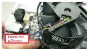
text_image
PressDown (4Places)
If you press down the fasteners without rotating them clockwise, the heatsink cannot be secured on the motherboard.
Step 5. Connect fan header with the CPU fan connector on the motherboard.
Step 6. Secure excess cable with tie-wrap to ensure cable does not interfere with fan operation or contact other components.
2.5 Installation of Memory Modules (DIMM)
This motherboard provides two 240-pin DDR3 (Double Data Rate 3) DIMM slots, and supports Dual Channel Memory Technology. For dual channel configuration, you always need to install two identical (the same brand, speed, size and chip-type) memory modules in the DDR3 DIMM slots to activate Dual Channel Memory Technology. Otherwise, it will operate at single channel mode.

- It is not allowed to install a DDR or DDR2 memory module into DDR3 slot; otherwise, this motherboard and DIMM may be damaged.
- If you install only one memory module or two non-identical memory modules, it is unable to activate the Dual Channel Memory Technology.
- Some DDR3 1GB double-sided DIMMs with 16 chips may not work on this motherboard. It is not recommended to install them on this motherboard.
Installing a DIMM

Please make sure to disconnect power supply before adding or removing DIMMs or the system components.
Step 1. Unlock a DIMM slot by pressing the retaining clips outward.
Step 2. Align a DIMM on the slot such that the notch on the DIMM matches the break on the slot.

text_image
O ↓ notch ← break × ↓ notch ← break
The DIMM only fits in one correct orientation. It will cause permanent damage to the motherboard and the DIMM if you force the DIMM into the slot at incorrect orientation.
Step 3. Firmly insert the DIMM into the slot until the retaining clips at both ends fully snap back in place and the DIMM is properly seated.
2.6 Expansion Slots (PCI Express Slots)
There are 2 PCI Express slots on this motherboard.
PCIE slots:
PCIE1 (PCIE 3.0 x16 slot) is used for PCI Express x16 lane width graphics cards.
PCIE2 (PCIE 2.0 x1 slot) is used for PCI Express x1 lane width cards.

Only PCIE1 slot supports Gen 3 speed. To run the PCI Express in Gen 3 speed, please install an Ivy Bridge CPU. If you install a Sandy Bridge CPU, the PCI Express will run only at PCI Express Gen 2 speed.
Installing an expansion card
Step 1. Before installing the expansion card, please make sure that the power supply is switched off or the power cord is unplugged. Please read the documentation of the expansion card and make necessary hardware settings for the card before you start the installation.
Step 2. Remove the system unit cover (if your motherboard is already installed in a chassis).
Step 3. Remove the bracket facing the slot that you intend to use. Keep the screws for later use.
Step 4. Align the card connector with the slot and press firmly until the card is completely seated on the slot.
Step 5. Fasten the card to the chassis with screws.
Step 6. Replace the system cover.
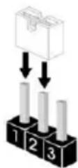
2.7 Jumpers Setup
The illustration shows how jumpers are setup. When the jumper cap is placed on pins, the jumper is "Short". If no jumper cap is placed on pins, the jumper is "Open". The illustration shows a 3-pin jumper whose pin1 and pin2 are "Short" when jumper cap is placed on these 2 pins.

Short
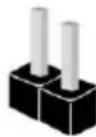
Open
Jumper Setting Description
Clear CMOS Jumper
(CLRCMOS1)
(see p.13, No. 14)


Clear CMOSDefault
Note: CLRCMOS1 allows you to clear the data in CMOS. To clear and reset the system parameters to default setup, please turn off the computer and unplug the power cord from the power supply. After waiting for 15 seconds, use a jumper cap to short pin2 and pin3 on CLRCMOS1 for 5 seconds. However, please do not clear the CMOS right after you update the BIOS. If you need to clear the CMOS when you just finish updating the BIOS, you must boot up the system first, and then shut it down before you do the clear-CMOS action. Please be noted that the password, date, time and user default profile will be cleared only if the CMOS battery is removed.

If you clear the CMOS, the case open may be detected. Please adjust the BIOS option "Clear Status" to clear the record of previous chassis intrusion status.
2.8 Onboard Headers and Connectors

Onboard headers and connectors are NOT jumpers. Do NOT place jumper caps over these headers and connectors. Placing jumper caps over the headers and connectors will cause permanent damage of the motherboard!
Serial ATA2 Connectors These four Serial ATA2
(SATA_0: see p.13, No. 7) (SATA2) connectors support
(SATA_1: see p.13, No. 6) SATA data enables for internal
(SATA_2: see p.13, No. 9) storage devices [The current
(SATA_3: see p.13, No. 8) SATA2Interface allows up to
3.0 Gb/s data transfer rate.
Serial ATA (SATA) Either end of the SATA data
Data Cable cable can be connected to the
(Optional) SATA / SATA2 hard disk or the
SATA2 connector on this motherboard.
USB 2.0 Headers Besides four default USB 2.0
(9-pin USB4_5) ports on the I/O panel, there
(see p.13 No. 13) are two USB 2.0 headers on
this motherboard. Each
USB 2.0 header can support
two USB 2.0 ports.
(9-pin USB6_7)
(see p.13 No. 12)
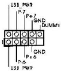
text_image
USB PWR P-7 P+7 GND DUMMY 1 GND P-6 P-6 USB PWRInfrared Module Header
(5-pin IR1)
(see p.13 No. 17)

This header supports an optional wireless transmitting and receiving infrared module.
Front Panel Audio Header This is an interface for front
(9-pin HD_AUDIO1) panel audio cable that allows
(see p.13 No. 18) convenient connection and
control of audio devices.
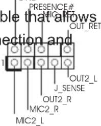
text_image
PRESENCE# MIG_RET OUT_RET ble that afflo ection and 1 J_SENSE OUT2_R MIC2_R MIC2_L OUT2_L
-
High Definition Audio supports Jack Sensing, but the panel wire on the chassis must support HDA to function correctly. Please follow the instruction in our manual and chassis manual to install your system.
-
If you use AC'97 audio panel, please install it to the front panel audio header as below:
A. Connect Mic_IN (MIC) to MIC2_L.
B. Connect Audio_R (RIN) to OUT2_R and Audio_L (LIN) to OUT2_L.
C. Connect Ground (GND) to Ground (GND).
D. MIC_RET and OUT_RET are for HD audio panel only. You don't need to connect them for AC'97 audio panel.
E. To activate the front mic.
For Windows ^® XP / XP 64-bit OS:
Select "Mixer". Select "Recorder". Then click "FrontMic".
For Windows ^ 8.1 / 8.1 64-bit / 8 / 8 64-bit / 7 / 7 64-bit / Vista ^TM / Vista ^TM 64-bit OS:
Go to the "FrontMic" Tab in the Realtek Control panel. Adjust "Recording Volume".
System Panel Header This header accommodates
(9-pin PANEL1) several system front panel
(see p.13 No. 11) functions.
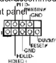
text_image
PTD- WRBIN# GND H DUMMY RESET# GND HDLED- HDLED+
Connect the power switch, reset switch and system status indicator on the chassis to this header according to the pin assignments below. Note the positive and negative pins before connecting the cables.
PWRBTN (Power Switch):
Connect to the power switch on the chassis front panel. You may configure the way to turn off your system using the power switch.
RESET (Reset Switch):
Connect to the reset switch on the chassis front panel. Press the reset switch to restart the computer if the computer freezes and fails to perform a normal restart.
PLED (System Power LED):
Connect to the power status indicator on the chassis front panel. The LED
is on when the system is operating. The LED keeps blinking when the system is in S1 sleep state. The LED is off when the system is in S3/S4 sleep state or powered off (S5).
HDLED (Hard Drive Activity LED):
Connect to the hard drive activity LED on the chassis front panel. The LED is on when the hard drive is reading or writing data.
The front panel design may differ by chassis. A front panel module mainly consists of power switch, reset switch, power LED, hard drive activity LED, speaker and etc. When connecting your chassis front panel module to this header, make sure the wire assignments and the pin assign-ments are matched correctly.
Power LED Header Please connect the chassis
(3-pin PLED1) power LED to this header to
(see p.13 No. 10) indicate system power status.
The LED is on when the system
is operating. The LED keeps
blinking in S1 state. The LED is
off in S3/S4 state or S5 state
(power off).
Chassis Fan Connector Please connect the fan cables
(4-pin CHA_FAN1) to the fan connectors and
(see p.13 No. 5) match the black wire to the
ground pin.
CPU Fan Connectors Please connect the CPU fan
(4-pin CPU_FAN1) cable to the connector and
(see p.13 No. 2) match the black wire to the
ground pin.
CPU_FAN_SPEED
FAN SPEED CONTROL

Though this motherboard provides 4-Pin CPU fan (Quiet Fan) support, the 3-Pin
CPU fan still can work successfully even without the fan speed control function.
If you plan to connect the 3-Pin CPU fan to the CPU fan connector on this motherboard, please connect it to Pin 1-3.
Pin 1-3 Connected

3-Pin Fan Installation
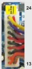
ATX Power Connector Please connect an ATX power
(24-pin ATXPWR1) supply to this connector.
(see p.13 No. 4)
1 13

Though this motherboard provides 24-pin ATX power connector, it can still work if you adopt a traditional 20-pin ATX power supply. To use the 20-pin ATX power supply, please plug your power supply along with Pin 1 and Pin 13.
20-Pin ATX Power Supply Installation
12
ATX 12V Power Connector Please connect an ATX 12V
(4-pin ATX12V1) power supply to this connector.
(see p.13 No. 1)
Chassis Intrusion Header This motherboard supports
(2-pin CI1) CASE OPEN detection feature
(see p.13, No. 15) that detects if the chassis cover
has been removed. This feature
requires a chassis with chassis
intrusion detection design.
SPDIF Out Connector Please connect the
(2-pin SPDIF_OUT1) SPDIF_OUT connector of a
(see p.13, No. 19) HDMI VGA card to this header
with a cable.
LPC/TPM Header This connector supports
(13-pin LPC/TPM1) Trusted Platform Module (TPM)
(see p.13, No. 16) system, which can securely
store keys, digital certificates, passwords, and data. A TPM system also helps enhance network security, protects digital identities, and ensures platform integrity.
| PIN | Signal Name | PIN | Signal Name | |
| 14 | +3V | 13 | No pin | |
| 12 | +3V | 11 | +3V | |
| 10 | GND | 9 | GND | |
| 8 | LAD3 | 7 | LAD2 | |
| 6 | LAD1 | 5 | LAD0 | |
| 4 | LFRAME# | 3 | RESET# | |
| 2 | GND | 1 | CLK | |
2.9 Driver Installation Guide
To install the drivers to your system, please insert the support CD to your optical drive first. Then, the drivers compatible to your system can be auto-detected and listed on the support CD driver page. Please follow the order from up to bottom side to install those required drivers. Therefore, the drivers you install can work properly.
Chapter 3: UEFI SETUP UTILITY
3.1 Introduction
This section explains how to use the UEFI SETUP UTILITY to configure your system. The UEFI chip on the motherboard stores the UEFI SETUP UTILITY. You may run the UEFI SETUP UTILITY when you start up the computer. Please press during the Power-On-Self-Test (POST) to enter the UEFI SETUP UTILITY, otherwise, POST will continue with its test routines.
If you wish to enter the UEFI SETUP UTILITY after POST, restart the system by pressing

Because the UEFI software is constantly being updated, the following UEFI setup screens and descriptions are for reference purpose only, and they may not exactly match what you see on your screen.
3.1.1 UEFI Menu Bar
The top of the screen has a menu bar with the following selections:
Main To set up the system time/date information
OC Tweaker To set up overclocking features
Advanced To set up the advanced UEFI features
Tool Useful tools
H/W Monitor To display current hardware status
Boot To set up the default system device to locate and load the Operating System
Security To set up the security features
Exit To exit the current screen or the UEFI SETUP UTILITY
Use <←> key or <→> key to choose among the selections on the menu bar, and then press
3.1.2 Navigation Keys
Please check the following table for the function description of each navigation key.
Navigation Key(s) Function Description
← / Moves cursor left or right to select Screens
↑ / ↓ Moves cursor up or down to select items
+ / - To change option for the selected items
3.2 Main Screen
When you enter the UEFI SETUP UTILITY, the Main screen will appear and display the system overview.

text_image
/ISRock UEFI Setup Utility File X: Taiwan Advanced Tools New Computer Boot Security Exit IDE1 Version Microsoft Teams Advanced Tools New Computer Boot Security Exit Processor Type Microsoft COM/THI JT-2000 EPV & O-00040 Processor Speed Microsoft Microcode Update Microsoft/20 Dynamic Style ELEMM Total Memory ZC499E with ZC499E Shared Memory and Intel KIT Memory Google Channel Memory Mode BONE_A1 NHD BONE_B1 ZC499E (Microsoft) def details via OF code Tomorrow's Technology Today Wed 05/20/2013, 05:57:323.3 OC Tweaker Screen
In the OC Tweaker screen, you can set up overclocking features.

text_image
ASRock UEFI Setup Utility MEAT 100% 200% 300% 400% 500% 600% 700% 800% 900% 1000% 1100% 1200% 1300% 1400% 1500% 1600% 1700% 1800% 1900% 2000% 2100% 2200% 2300% 2400% 2500% 2600% 2700% 2800% 2900% 3000% 3100% 3200% 3300% 3400% 3500% 3600% 3700% 3800% 3900% 4000% 4100% 4200% 4300% 4400% 4500% 4600% 4700% 4800% 4900% 5000% 5100% 5200% 5300% 5400% 5500% 5600% 5700% 5800% 5900% 6000% 6100% 6200% 6300% 6400% 6500% 6600% 6700% 6800% 6900% 7000% 7100% 7200% 7300% 7400% 7500% 7600% 7700% 7800% 7900% 8000% 8100% 8200% 8300% 8400% 8500% 8600% 8700% 8800% 8900% 9000% 9100% 9200% 9300% 9400% 9500% 9600% 9700% 9800% 9900% 1.1.1.1.1.1.1.1.1.1.1.1.1.1.1.1.1.1.1.1.1.1.1.1.1.1.1.1.1.1.1.1.1.1.1.1.1.1.1.1.1.1.1.1.1.1.1.1.1.1.1 CPU Configuration CPU Headset INTU Technologies Technologies Dout Turbo Boost Technologies Long Duration Power Limit Long Duration Precision Short Duration Power Limit Primary Plane Current Limit Secondary Plane Current Limit GT Over-Cocking Support Below Timing Configuration Driver Frequency SOFD-1466 (1/4) Driver Configuration Voltage Configuration TOMMOW'S Technology Today Auto Auto Auto Auto Auto Auto Auto Auto Auto Auto Auto Auto Auto Auto Auto Auto Auto Auto Auto Auto Auto Auto Auto Auto Auto Auto Auto Auto Auto Auto Auto Auto Auto Auto Auto Auto Auto Auto Auto Auto Auto Auto Auto Auto Auto Auto Auto Auto Auto Auto AUTO AUTO AUTO AUTO AUTO AUTO AUTO AUTO AUTO AUTO AUTO AUTO AUTO AUTO AUTOCPU Configuration
CPU Ratio
Use this item to change the ratio value of this motherboard.
Intel SpeedStep Technology
Intel SpeedStep technology is Intel's new power saving technology. Processors can switch between multiple frequencies and voltage points to enable power saving. The default value is [Enabled]. Configuration options: [Enabled] and [Disabled]. If you install Windows ^ Vista ^TM / 7 / 8 / 8.1 and want to enable this function, please set this item to [Enabled]. This item will be hidden if the current CPU does not support Intel SpeedStep technology.

Please note that enabling this function may reduce CPU voltage and lead to system stability or compatibility issues with some power supplies. Please set this item to [Disabled] if above issues occur.
Intel Turbo Boost Technology
Use this item to enable or disable Intel Turbo Boost Mode Technology. Turbo Boost Mode allows processor cores to run faster than marked frequency in specific conditions. The default value is [Enabled].
Long Duration Power Limit
Use this item to configure long duration power limit in watts. The default value is [Auto].
Long Duration Maintained
Use this item to configure time window which the long duration power is maintained. The default value is [Auto].
Short Duration Power Limit
Use this item to configure short duration power limit in watts. The default value is [Auto].
Primary Plane Current Limit
Use this item to configure the maximum instantaneous current allowed for the primary plane. The default value is [Auto].
Secondary Plane Current Limit
Use this item to configure the maximum instantaneous current allowed for the secondary plane. The default value is [Auto].
GT OverClocking Support
Use this item to enable or disable GT OverClocking Support. The default value is [Disabled].
DRAM Timing Configuration
Load XMP Setting
Use this to load XMP setting. Configuration options: [Auto], [Default], [Profile 1] and [Profile 2]. The default value is [Auto].
DRAM Frequency
If [Auto] is selected, the motherboard will detect the memory module(s) inserted and assign the appropriate frequency automatically.
DRAM Configuration
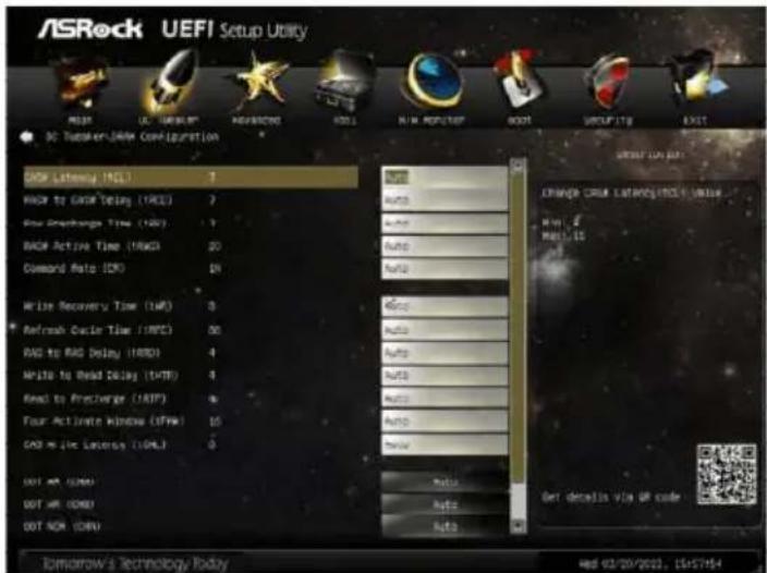
text_image
ASRock UEFI Setup Utility MAIN UL CABBEG AGNARDO ROLL RUN REGITER BOOT OUTPUTING EXIT 3C: Tsubmer/DAW Configuration SOD Latency (MCL) 7 RAC to GRC Delay (RCE) 7 Four Speedamps Time (RSP) 1 RAC Active Time (RAG) 20 Command Rate (CR) 20 Write Recovery Time (WR) 3 Refresh Cycle Time (RRC) 60 RAG to RAG Delay (RBD) 4 Write to Read Delay (TAT) 4 Read to PreChange (RTP) 6 Four Active Windows (SFM) 15 CAS Max Latency (LMT) 5 DOT AM (OM) DOT AR (OM) DOT NOM (OM) Auto Auto Auto Auto Auto Auto Auto Auto Auto Auto Auto Auto Auto Auto Auto Auto Auto Auto Auto Auto Auto Auto Auto Auto Auto Auto Auto Auto Auto Auto Auto Auto Auto Auto Auto Auto Auto Auto Auto Auto Auto Auto Auto Auto Auto Auto Auto Auto Auto Auto AutoDRAM tCL
Use this item to change CAS# Latency (tCL) Auto/Manual setting. The default is [Auto].
DRAM tRCD
Use this item to change RAS# to CAS# Delay (tRCD) Auto/Manual setting. The default is [Auto].
DRAM tRP
Use this item to change Row Precharge Time (tRP) Auto/Manual setting.
The default is [Auto].
DRAM tRAS
Use this item to change RAS# Active Time (tRAS) Auto/Manual setting.
The default is [Auto].
Command Rate (CR)
Use this item to change Command Rate (CR) Auto/Manual setting. The default is [Auto].
DRAM tWR
Use this item to change Write Recovery Time (tWR) Auto/Manual setting.
The default is [Auto].
DRAM tRFC
Use this item to change Refresh Cyle Time (tRFC) Auto/Manual setting.
The default is [Auto].
DRAM tRRD
Use this item to change RAS to RAS Delay (tRRD) Auto/Manual setting.
The default is [Auto].
DRAM tWTR
Use this item to change Write to Read Delay (tWTR) Auto/Manual setting.
The default is [Auto].
DRAM tRTP
Use this item to change Read to Precharge (tRTP) Auto/Manual setting.
The default is [Auto].
DRAM tFAW
Use this item to change Four Activate Window (tFAW) Auto/Manual set-
ting. The default is [Auto].
DRAM tCWL
Use this item to change CAS# Write Latency (tCWL) Auto/Manual setting.
The default is [Auto].
ODT WR (CHA)
Use this item to change ODT WR (CHA) setting. The default is [Auto].
ODT WR (CHB)
Use this item to change ODT WR (CHB) setting. The default is [Auto].
ODT NOM (CHA)
Use this item to change ODT NOM (CHA) setting. The default is [Auto].
ODT NOM (CHB)
Use this item to change ODT NOM (CHB) setting. The default is [Auto].
MRC Fast Boot
Use this item to enable or disable MRC Fast Boot. The default is [Enabled].
Voltage Configuration
DRAM Voltage
Use this to select DRAM Voltage. The default value is [Auto].
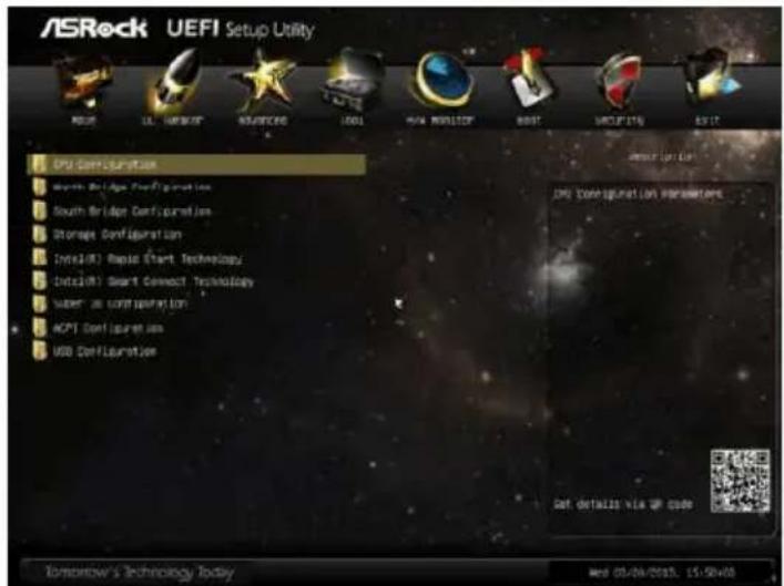
3.4 Advanced Screen
In this section, you may set the configurations for the following items: CPU Configuration, North Bridge Configuration, South Bridge Configuration, Storage Configuration, Intel(R) Rapid Start Technology, Intel(R) Smart Connect Technology, Super IO Configuration, ACPI Configuration and USB Configuration.
text_image
ASRock UEFI Setup Utility CPU Configuration Smart Bridge Configuration South Bridge Configuration Storage Configuration Intel(R) Realo Start Technology Dialu(R) Smart Connect Technology Water & Storage Configuration ACPT Configuration USB Configuration System Setup CPU Configuration Parameters Get Details Via UP Code Tomorrow's Technology Today Add 01/04/2023, 15:50:00
Setting wrong values in this section may cause the system to malfunction.
3.4.1 CPU Configuration

text_image
ASRock UEFI Setup Utility NEW UL UBEERY NEVERCOS KIDS RUN MONITOR BOOT SECURITY LIST Advanced/CPU Configuration Intel(0) CorelTH: US-2000 OPE M 2.000Ae Max CPU Speed: 2000 MHz Max CPU Speed: 5000 MHz Processor Caps: 4 Intel UI Technologies: Not Supported Integrated Not Supported Integrated Number of cores to enable if open processor package. Intel UI Technologies: Not Supported Integrated Intel Processor Caps: Enhanced Anti State(GIF) CPU CS State Support: CPU CS State Support: Package C State Support: CPU Thermal Throttling: No Event Memory Protection Intel virtualization Technology Hardware Protectioner Adjacent Cache Line Protection Enabled Enabled Enabled Enabled Enabled Get details via All code Tomorrow's Technology Today Wed 03/20/2001, US/StateIntel Hyper Threading Technology
To enable this feature, a computer system with an Intel processor that supports Hyper-Threading technology and an operating system that includes optimization for this technology, such as Microsoft ^ Windows ^ XP / Vista ^TM / 7 / 8 / 8.1 is required. Set to [Enabled] if using Microsoft ^ Windows ^ XP, Vista ^TM , 7, 8, 8.1 or Linux kernel version 2.4.18 or higher. This option will be hidden if the installed CPU does not support Hyper-Threading technology.
Active Processor Cores
Use this item to select the number of cores to enable in each processor package. The default value is [All].
Enhance Halt State (C1E)
All processors support the Halt State (C1). The C1 state is supported through the native processor instructions HLT and MWAIT and requires no hardware support from the chipset. In the C1 power state, the processor maintains the context of the system caches.
CPU C3 State Support
Use this to enable or disable CPU C3 (ACPI C2) report to OS.
CPU C6 State Support
Use this to enable or disable CPU C6 (ACPI C3) report to OS.
Package C State Support
Selected option will program into C State package limit register. The default value is [Auto].
CPU Thermal Throttling
You may select [Enabled] to enable CPU internal thermal control mechanism to keep the CPU from overheating.
No-Execute Memory Protection
No-Execution (NX) Memory Protection Technology is an enhancement to the IA-32 Intel Architecture. An IA-32 processor with “No Execute (NX) Memory Protection” can prevent data pages from being used by malicious software to execute codes. This option will be hidden if the current CPU does not support No-Excute Memory Protection.
Intel Virtualization Technology
When this option is set to [Enabled], a VMM (Virtual Machine Architecture) can utilize the additional hardware capabilities provided by Vanderpool Technology. This option will be hidden if the installed CPU does not support Intel Virtualization Technology.
Hardware Prefetcher
Use this item to turn on/off the MLC streamer prefetcher.
Adjacent Cache Line Prefetch
Use this item to turn on/off prefetching of adjacent cache lines.
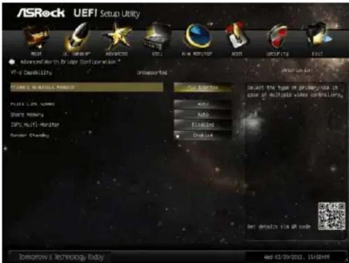
3.4.2 North Bridge Configuration
text_image
ASRock UEFI Setup Utility RIGHT UL SUPERIOR ADVANCED SODI Advanced/Earth Bridge Configuration * VR-6 Capability Unassorted Future's Wireless Master Out Starter Multi Ratio Disabled ONLINE Select the type of primary user in case of multiple video controllers. Get details via QR code Tomorrow's Technology Today Wed 02/29/2022, $1450499Primary Graphics Adapter
This allows you to select [Onboard] or [PCI Express] as the boot graphic adapter priority. The default value is [PCI Express].
VT-d
Use this to enable or disable Intel ^ VT-d technology (Intel ^ Virtualization Technology for Directed I/O). The default value of this feature is [Disabled].
PCIE1 Link Speed
This allows you to select PCIE1 Link Speed. The default value is [Auto].
Share Memory
This allows you to set onboard VGA share memory feature. The default value is [Auto].
IGPU Multi-Moniter
This allows you to enable or disable IGPU Multi-Moniter. The default value is [Enabled]. If you install the PCI Express card under Windows ^ XP / Vista ^TM OS, please disable this option.
Render Standby
Use this to enable or disable Render Standby by Internal Graphics Device. The default value is [Enabled].
3.4.3 South Bridge Configuration

text_image
ASRock UEFI Setup Utility MOSI U.S. UBEAVY NEVOCING KOD MAIN RECOFFIC ROOT SUPPORTING EXIT Advanced Security Bridge Configuration * Forward Web Audio Power Panel Anboard Blind HD Audio Recorded LAN Deep Display Restore on HD-Power Loss Good Audio LCD Auto Auto Enabled Enabled Enabled Power Off Auto AUTO/TIMECON/OLEMON ENGLISH NO Audio Get details via @ code Tomorrow's Technology Today http://03/09/2010, 15:18:12Onboard HD Audio
Select [Auto], [Enabled] or [Disabled] for the onboard HD Audio feature. If you select [Auto], the onboard HD Audio will be disabled when PCI Sound Card is plugged.
Front Panel
Select [Auto] or [Disabled] for the onboard HD Audio Front Panel.
Onboard LAN
This allows you to enable or disable the Onboard LAN feature.
Deep Sleep
Mobile platforms support Deep S4/S5 in DC only and desktop platforms support Deep S4/S5 in AC only. The default value is [Enabled in S5].
Restore on AC/Power Loss
This allows you to set the power state after an unexpected AC/power loss. If [Power Off] is selected, the AC/power remains off when the power recovers. If [Power On] is selected, the AC/power resumes and the system starts to boot up when the power recovers.
Good Night LED
Use this item to enable or disable Power LED and LAN LED.
3.4.4 Storage Configuration

text_image
ASRock UEFI Setup Utility MOSI UL NIKKPT ADVANCED SODI RUN NIK KONK TROST SICRU TIG EXIT Advanced/Scroger, Conf. (aurati)lon SATA Controls(Annis) SATA Solar Select Line SATA Aggressive Line Power Management Hard Dock G.M.P.R.T DATNL_1 - Not Detected DATNL_2 - Not Detected DATNL_3 - Not Detected DATNL_4 - Not Detected DATNL_5 - Not Detected DATNL_6 - Not Detected Enabled UnT Enabled Enabled System Use Line Enable OF GLOBAL DATA DEVICES GET ITEMS V1G SP CODE Tomorrow's Technology Today Next 03/09/2021, 15:58:27SATA Controller(s)
Use this item to enable or disable the SATA Controller feature.
SATA Mode Selection
Use this to select SATA mode. Configuration options: [IDE Mode], [AHCI Mode] and [Disabled]. The default value is [AHCI Mode].

AHCI (Advanced Host Controller Interface) supports NCQ and other new features that will improve SATA disk performance but IDE mode does not have these advantages.
SATA Aggressive Link Power Management
Use this item to configure SATA Aggressive Link Power Management.
Hard Disk S.M.A.R.T.
Use this item to enable or disable the S.M.A.R.T. (Self-Monitoring, Analysis, and Reporting Technology) feature. Configuration options: [Disabled] and [Enabled].
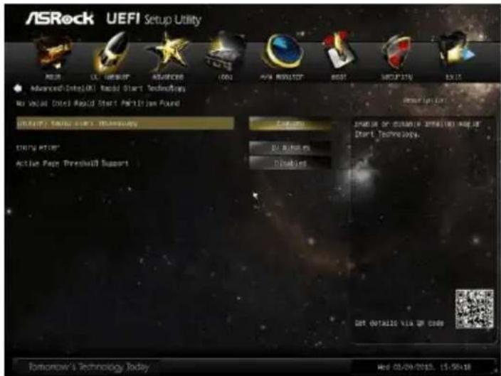
3.4.5 Intel(R) Rapid Start Technology
text_image
ASRock UEFI Setup Utility NEER SL. INSTRAT ADVANCED COM 100 Advanced Site (UK) Real Start Technologies No virtual Dotel Rapid Start Partition Found USEUM: New user's Software Active HTR Active Page Preshall Support Customs D:\Users\Disables Set Detallic XIA UP CODE Tomorrow's Technology Today Web 03/09/2015, 15:50:18Intel(R) Rapid Start Technology
Use this item to enable or disable Intel(R) Rapid Start Technology. Intel(R) Rapid Start Technology is a new zero power hibernation mode which allows users to resume in just 5-6 seconds. The default is [Enabled].
Entry After
Select a time to enable RTC wake timer at S3 entry. The default is [10 minutes].
Active Page Threshold Support
This allows you to enable or disable Active Page Threshold Support. The default is [Disabled].
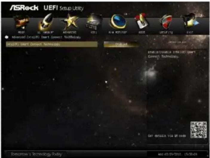
3.4.6 Intel(R) Smart Connect Technology
text_image
ASRock UEFI Setup Utility MOST UL SNER IT ADVANCED 3000 Advanced Lite(UK) Smart Connect Technology Details Smart Connect Technology Enabled System Status System Status: None/Not Smart Connect Technology... Det: https://123.com/ Tomorrow's Technology Today Add 63/29/2001, 15:58:44Intel(R) Smart Connect Technology
Use this item to enable or disable Intel(R) Smart Connect Technology. Intel(R) Smart Connect Technology keeps your e-mail and social networks, such as Twitter, Facebook, etc. updated automatically while the computer is in sleep mode. The default is [Enabled].
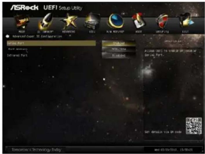
3.4.7 Super IO Configuration
text_image
ASRock UEFI Setup Utility MOST US 100% AVRICO AVRICO BDO RUN ROFT/POP BOOT MINTUING EXIT Advanced Super: 10 Configuration Serial Port Port Address Infrared Port Checked WIN-TS44 Installed ASIOME UEFI TO KIMBO OF UP CREAM UP Serial Port. GET DETAILS VIA UN CODE Tomorrow's Technology Today Wed 03/29/2012, 15:58:25Serial Port
Use this item to enable or disable the onboard serial port.
Port Address
Use this item to set the address for the onboard serial port.
Configuration options: [3F8 / IRQ4] and [3E8 / IRQ4].
Infrared Port
Use this item to enable or disable the onboard infrared port.
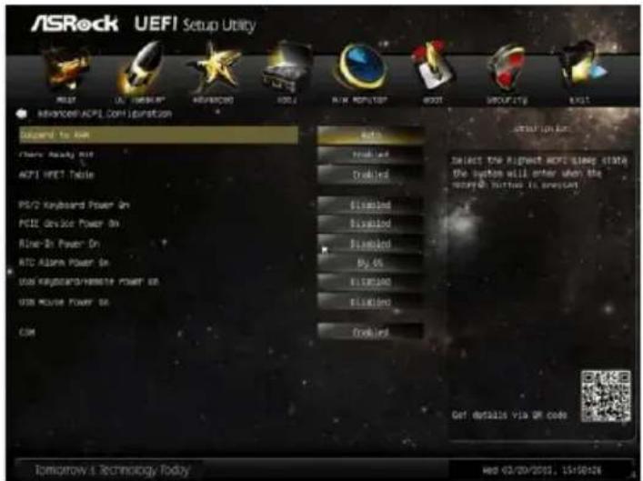
3.4.8 ACPI Configuration
text_image
ASRock UEFI Setup Utility MOST US SHORT ADVANCED INFO RUN SMART ROOT SECURITY EXIT ADVANCED ACFE COM Optimization Choose to run Share Ready on ACFI MERT Table PCI/2 Keyboard Power On PCIe Device Power On Rine-In Power On RTC Alarm Power On USB Keyboard/Chrome Power On USB Mouse Power On COM Auto Enabled Disabled Enabled Enabled By 06 Enabled Enabled Enabled Get details via OR code Tomorrow & Technology Today Get details via OR codeSuspend to RAM
Use this item to select whether to auto-detect or disable the Suspend-to-RAM feature. Selecting [Auto] will enable this feature if the OS supports it.
Check Ready Bit
Use this item to enable or disable the feature Check Ready Bit.
ACPI HPET Table
Use this item to enable or disable ACPI HPET Table. The default value is [Enabled]. Please set this option to [Enabled] if you plan to use this motherboard to submit Windows ^® certification.
PS/2 Keyboard Power On
Use this item to enable or disable PS/2 keyboard to turn on the system from the power-soft-off mode.
PCIE Device Power On
Use this item to enable or disable PCIE devices to turn on the system from the power-soft-off mode.
Ring-In Power On
Use this item to enable or disable Ring-In signals to turn on the system from the power-soft-off mode.
RTC Alarm Power On
Use this item to enable or disable RTC (Real Time Clock) to power on the system.
USB Keyboard/Remote Power On
Use this item to enable or disable USB Keyboard/Remote to turn on the system from the power-soft-off mode.
USB Mouse Power On
Use this item to enable or disable USB Mouse to turn on the system from the power-soft-off mode.
CSM
Please disable CSM when you enable Fast Boot option. The default value is [Enabled].
3.4.9 USB Configuration

text_image
ASRock UEFI Setup Utility NEW OK NEW START NEW NEW NEW NEW Advanced USB Configuration USB 2.0 Customizer Legacy USB System USB Connection Utility Patch Enabled Enabled Enabled IN W markets or database I/O 2.0 Controller. GET: dMS1235 V13.2P 0089 Tomorrow's Technology Today Get 02/03/2002, 15:15D:20USB 2.0 Controller
Use this item to enable or disable the use of USB 2.0 controller.
Legacy USB Support
Use this option to select legacy support for USB devices. There are four configuration options: [Enabled], [Auto], [Disabled] and [UEFI Setup Only]. The default value is [Enabled]. Please refer to below descriptions for the details of these four options:
[Enabled] - Enables support for legacy USB.
[Auto] - Enables legacy support if USB devices are connected.
[Disabled] - USB devices are not allowed to use under legacy OS and UEFI setup when [Disabled] is selected. If you have USB compatibility issue, it is recommended to select [Disabled] to enter OS.
[UEFI Setup Only] - USB devices are allowed to use only under UEFI setup and Windows / Linux OS.
3.5 Tool

text_image
ASRock UEFI Setup Utility MOYA US CABBUS AEROSICO FODI NUA MOUNT ROOT SUCFETY LIST USECURE Management Guard UEFI Update Utility UNSTOCK PLAN Internet Flash - DAP (Auto 2P), Europe Network Configuration Dehumidifier Function Would you like to save current setting as user defaults? Save 1st User Default User Default 1) Save 2nd User Default User Default 2) Save 3rd User Default User Default 3) TOMAROW'S Technology Today ADMINISTRATORS AND BASE TO establish an Internet command or certificate. Internet Service is specified via Open Get details via QR code http://03/03/2002, 15156194OMG(Online Management Guard)
Administrators are able to establish an internet curfew or restrict internet access at specified times via OMG. You may schedule the starting and ending hours of internet access granted to other users. In order to prevent users from bypassing OMG, guest accounts without permission to modify the system time are required.
UEFI Update Utility
Instant Flash
Instant Flash is a UEFI flash utility embedded in Flash ROM. This convenient UEFI update tool allows you to update system UEFI without entering operating systems first like MS-DOS or Windows ^® . Just save the new UEFI file to your USB flash drive, floppy disk or hard drive and launch this tool, then you can update your UEFI only in a few clicks without preparing an additional floppy diskette or other complicated flash utility. Please be noted that the USB flash drive or hard drive must use FAT32/16/12 file system. If you execute Instant Flash utility, the utility will show the UEFI files and their respective information. Select the proper UEFI file to update your UEFI, and reboot your system after the UEFI update process is completed.
Internet Flash
Internet Flash searches for available UEFI firmware updates from our servers. In other words, the system can auto-detect the latest UEFI from our servers and flash them without entering Windows OS.
Network Configuration

text_image
ASRock UEFI Setup Utility Power USB NETWORKS RESOURCES I/O/U NEW TARGET HOST GROUPS EXIT Power Networks: COM UPONION.COM Internet Setting USEU - (Get a SP) Options Power Up List setup: Internet Connection 2008 SET: 0014135 V1.0 @ 2008 Tomorrow's Technology Today USE 03/29/2012, 15:50:20Internet Setting
Use this item to set up the internet connection mode. Configuration options: [DHCP (Auto IP)] and [PPPOE].
UEFI Download Server
Use this item to select UEFI firmware download server for Internet Flash. Configuration options: [Asia], [Europe], [USA] and [China].
Dehumidifier Function
Users may prevent motherboard damages due to dampness by enabling "Dehumidifier Function". When enabling Dehumidifier Function, the computer will power on automatically to dehumidify the system after entering S4/S5 state.
Dehumidifier Period
This allows users to configure the period of time until the computer powers on and enables "Dehumidifier" after entering S4/S5 state.
Dehumidifier Duration
This allows users to configure the duration of the dehumidifying process before it returns to S4/S5 state.
Dehumidifier CPU Fan Setting
Use this setting to configure CPU fan speed while "Dehumidifier" is enabled.
Would you like to save current setting user defaults?
In this option, you are allowed to load and save three user defaults according to your own requirements.
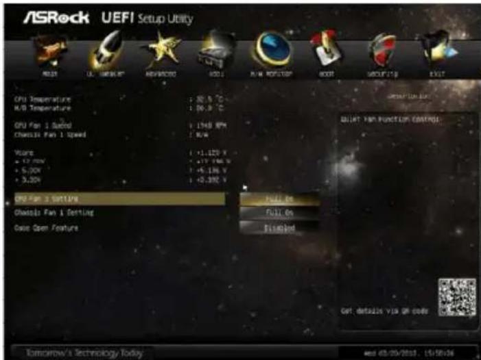
3.6 Hardware Health Event Monitoring Screen
In this section, it allows you to monitor the status of the hardware on your system, including the parameters of the CPU temperature, motherboard temperature, CPU fan speed, chassis fan speed, and the critical voltage.
text_image
ASRock UEFI Setup Utility NEW UL WORK NEVROSO SSD R/W ROCKET ROOT GROUP 100 EXIT CPU Temperature : 30.5 °C R/B Temperature : 30.3 °C CPU Fan 1 Sustel : 1948 RPM Chassis Fan 1 Speed : 8.6 Hours : +1.120 V + 12.70V : +1.176 V + 5.20V : +5.196 V + 5.20V : +0.392 V CPU Fan 2 Setting Chassis Fan 1 Setting Case Open Feature Full On Full On Finished Get details via QR code Tomorrow's Technology Today and 48/06/2018, 15/18/24CPU Fan 1 Setting
This allows you to set the CPU fan 1 speed. Configuration options: [Full On] and [Automatic Mode]. The default is value [Full On].
Chassis Fan 1 Setting
This allows you to set the Chassis fan 1 speed. Configuration options: [Full On] and [Automatic Mode]. The default is value [Full On].
Case Open Feature
This allows you to enable or disable case open detection feature. The default is value [Enabled].
Clear Status
This option appears only when the case open has been detected. Use this option to keep or clear the record of previous chassis intrusion status.
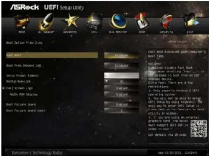
3.7 Boot Screen
In this section, it will display the available devices on your system for you to configure the boot settings and the boot priority.
text_image
ASRock UEFI Setup Utility NEAST UL-100000 ADJAMON HOST MAIN MONITOR BOOT GROUPING LAST Boot Option Priorities Last Best Boot From Unboost LAG Setup Project Tolerance Backup Bus-Lock Full Screen Logo Audio ROM Display Boot Failure Guard Boot Failure Break Support Last Best Last Best Options: Cableband Disable Fast Boot How to be allowed to boot from an USB Shipped device. Ultra Fast: There are a few Restrictions: 1. Only supports to Windows 8 UEFI operating system 2. You will not be able to enter UEFI Setup by using keyboard. The only way to enter UEFI. Options is control code on our "constant to save" utility in window. 3. If you are using an external graphics card, the value must support UEFI UDP in order, to level ? Get details via OR code Tomorrow's Technology Today Wed 02/20/2022, USRS645Fast Boot
Fast Boot minimizes your computer's boot time. There are three configuration options: [Disabled], [Fast] and [Ultra Fast]. The default value is [Disabled]. Please refer to below descriptions for the details of these three options:
[Disabled] - Disable Fast Boot.
[Fast] - The only restriction is you may not boot by using an USB flash drive.
[Ultra Fast] - There are a few restrictions.
- Only supports Windows ^® 8.1 / 8 UEFI operating system.
- You will not be able to enter BIOS Setup (Clear CMOS or run utility in Widows ^® to enter BIOS Setup).
- If you are using an external graphics card, the VBIOS must support UEFI GOP in order to boot.
Boot From Onboard LAN
Use this item to enable or disable the Boot From Onboard LAN feature.
Setup Prompt Timeout
This shows the number of seconds to wait for setup activation key. 65535(0xFFFF) means indefinite waiting.
Bootup Num-Lock
If this item is set to [On], it will automatically activate the Numeric Lock function after boot-up.
Full Screen Logo
Use this item to enable or disable OEM Logo. The default value is [Enabled].
AddOn ROM Display
Use this option to adjust AddOn ROM Display. If you enable the option "Full Screen Logo" but you want to see the AddOn ROM information when the system boots, please select [Enabled]. Configuration options: [Enabled] and [Disabled]. The default value is [Enabled].
Boot Failure Guard
Enable or disable the feature of Boot Failure Guard.
Boot Failure Guard Count
Enable or disable the feature of Boot Failure Guard Count.
3.8 Security Screen
In this section, you may set or change the supervisor/user password for the system. For the user password, you may also clear it.
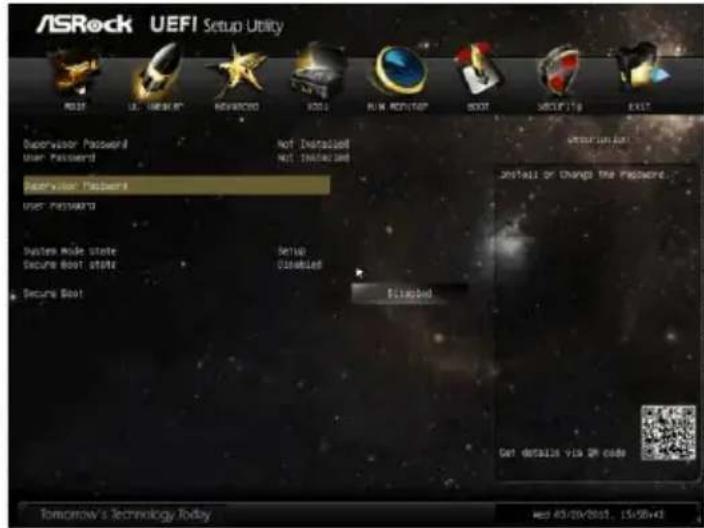
text_image
ASRock UEFI Setup Utility POST 15:00:00:00 ADVANCED POST RUN ROUTER BOOT SMOFTS EXIT Supervisor Password Not Disassembled User Password Not Disassembled Supervisor Password User Password System Mode State Setup Secure Boot state Cancelled Secure Boot Set up Disassembled Get details VIS OR code Tomorrow's Technology Today Wed 43/29/2001, 15:58:45Secure Boot
Use this to enable or disable Secure Boot. The default value is [Disabled].
3.9 Exit Screen
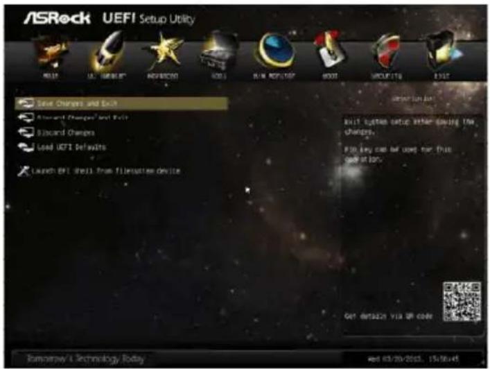
text_image
ASRock UEFI Setup Utility NEW YEAR 12 SEPTEMBER 2003 SaaS Changes and Exit Standard Changes and Exit Discount Changes Load UEFI Defaults Launch EPI Shell from filestation device Start system setup after leaving the changes. If to buy can be used for this code at 10%. Get out/2023 VIX OR CODE Eneronew/L Technology Today and 03/20/2023, 15/16/2014Save Changes and Exit
When you select this option, the following message "Save configuration changes and exit setup?" will pop-out. Select [Yes] to save the changes and exit the UEFI SETUP UTILITY.
Discard Changes and Exit
When you select this option, the following message “Discard changes and exit setup?” will pop-out. Select [Yes] to exit the UEFI SETUP UTILITY without saving any changes.
Discard Changes
When you select this option, the following message "Discard changes?" will pop-out. Select [Yes] to discard all changes.
Load UEFI Defaults
Load UEFI default values for all the setup questions. F9 key can be used for this operation.
Launch EFI Shell from filesystem device
Attempts to Launch EFI Shell application (Shell64.efi) from one of the available filesystem devices.
Chapter 4: Software Support
4.1 Install Operating System
This motherboard supports various Microsoft Windows® operating systems: 8.1 / 8.1 64-bit / 8 / 8 64-bit / 7 / 7 64-bit / Vista™ / Vista™ 64-bit / XP / XP 64-bit. Because motherboard settings and hardware options vary, use the setup procedures in this chapter for general reference only. Refer to your OS documentation for more information.
4.2 Support CD Information
The Support CD that came with the motherboard contains necessary drivers and useful utilities that enhance the motherboard features.
4.2.1 Running The Support CD
To begin using the support CD, insert the CD into your CD-ROM drive. The CD automatically displays the Main Menu if "AUTORUN" is enabled in your computer. If the Main Menu did not appear automatically, locate and double click on the file "ASRSETUP.EXE" from the BIN folder in the Support CD to display the menus.
4.2.2 Drivers Menu
The Drivers Menu shows the available devices drivers if the system detects installed devices. Please install the necessary drivers to activate the devices.
4.2.3 Utilities Menu
The Utilities Menu shows the applications software that the motherboard supports. Click on a specific item then follow the installation wizard to install it.
4.2.4 Contact Information
If you need to contact ASRock or want to know more about ASRock, welcome to visit ASRock's website at http://www.asrock.com; or you may contact your dealer for further information.
Installing OS on a HDD Larger Than 2TB
This motherboard is adopting UEFI BIOS that allows Windows ^ OS to be installed on a large size HDD (>2TB). Please follow below procedure to install the operating system.
- Please make sure to use Windows® Vista™ 64-bit (with SP1 or above), Windows® 7 64-bit or Windows® 8.1 / 8 64-bit.
- Press
or at system POST. Set AHCI Mode in UEFI Setup Utility > Advanced > Storage Configuration > SATA Mode. - Choose the item "UEFI:xxx" to boot in UEFI Setup Utility > Boot > Boot Option #1. ("xxx" is the device which contains your Windows® installation files. Normally it is an optical drive.) You can also press
to launch boot menu at system POST and choose the item "UEFI:xxx" to boot. - Start Windows ^® installation.
- If you install Windows® 7 64-bit OS, OS will be formatted by GPT (GUID Partition Table). Please install the hotfix file from Microsoft®: http://support.microsoft.com/kb/979903