Profile JGP656WBWW - Cooker GE - Free user manual and instructions
Find the device manual for free Profile JGP656WBWW GE in PDF.

User questions about Profile JGP656WBWW GE
0 question about this device. Answer the ones you know or ask your own.
Ask a new question about this device
Download the instructions for your Cooker in PDF format for free! Find your manual Profile JGP656WBWW - GE and take your electronic device back in hand. On this page are published all the documents necessary for the use of your device. Profile JGP656WBWW by GE.
USER MANUAL Profile JGP656WBWW GE
Cooktop Gas Downdraft
Safety Instructions
Safety precautions ....2, 4–7
Operating Instructions, Tips
Burners 9
Cookware tips .....10
Features of your cooktop . . .8
Vent system .....11
Care and Cleaning
Burner assemblies .....12
Burner caps ....13
Burner grates .....13
Burner heads .....13
Control knobs .....12
Glass cooktop .....12
Grease filters .....12
Installation Instructions
Installing the
cooktop .....14-16, 19-24
Installing the
downdraft system .....17-18
LP gas 7
Before You Call For Service
Troubleshooting tips .....25
Consumer Services
Important phone
numbers ....Back Cover
Model and serial number
location....3
Product registration .3, 29, 30
Warranty....31
Installation and Owner's Manual
JGP656

natural_image
Abstract decorative swirl pattern with no text or symbolsIMPORTANT SAFETY INFORMATION. READ ALL INSTRUCTIONS BEFORE USING.
WARNING: If the information in this manual is not followed exactly, a fire or explosion may result causing property damage, personal injury or death.
- Do not store or use gasoline or other flammable vapors and liquids in the vicinity of this or any other appliance.
- WHAT TO DO IF YOU SMELL GAS
■ Do not try to light any appliance.
- Do not touch any electrical switch; do not use any phone in your building.
Immediately call your gas supplier from a neighbor's phone. Follow the gas supplier's instructions.
If you cannot reach your gas supplier, call the fire department.
— Installation and service must be performed by a qualified installer, service agency or the gas supplier.

text_image
SF CERTIFIEDGE & You, A Service Partnership.

IMPORTANT!
Fill out the Consumer Product Registration Card.
Two easy ways to register your appliance!
■ Through the internet at www.geappliances.com
■ Complete and mail the enclosed Product Registration Card
FOR YOUR RECORDS
Write the model and serial numbers here:
#
#
You can find them on a label under the cooktop.
Staple sales slip or cancelled check here.
Proof of the original purchase date is needed to obtain service under the warranty.
READ THIS MANUAL
Inside you will find many helpful hints on how to use and maintain your cooktop properly. Just a little preventive care on your part can save you a great deal of time and money over the life of your cooktop.
IF YOU NEED SERVICE
You'll find many answers to common problems in the Before You Call For Service section. If you review our chart of Troubleshooting Tipsfirst, you may not need to call for service at all.
If you do need service, you can relax knowing help is only a phone call away. A list of toll-free customer service numbers is included in the back section of this manual. Or you can always call the GE Answer Center ^® at 800.626.2000, 24 hours a day, 7 days a week.
OR
Visit our Website at: www.geappliances.com
IMPORTANT SAFETY INFORMATION. READ ALL INSTRUCTIONS BEFORE USING.
WARNING!
For your safety, the information in this manual must be followed to minimize the risk of fire or explosion, electric shock, or to prevent property damage, personal injury, or loss of life.

IMPORTANT SAFETY NOTICE
The California Safe Drinking Water and Toxic Enforcement Act requires the Governor of California to publish a list of substances known to the state to cause cancer, birth defects or other reproductive harm, and requires businesses to warn customers of potential exposure to such substances.
Gas appliances can cause minor exposure to four of these substances, namely benzene, carbon monoxide, formaldehyde and soot, caused primarily by the incomplete combustion of natural gas or LP fuels. Properly adjusted burners, indicated by a bluish rather than a yellow flame, will minimize incomplete combustion. Exposure to these substances can be minimized by venting with an open window or using a ventilation fan or hood.

SAFETY PRECAUTIONS
Have the installer show you the location of the cooktop gas shut-off valve and how to shut it off if necessary.
- Have your cooktop installed and properly grounded by a qualified installer, in accordance with the Installation Instructions. Any adjustment and service should be performed only by qualified gas cooktop installers or service technicians.
- Do not attempt to repair or replace any part of your cooktop unless it is specifically recommended in this manual. All other service should be referred to a qualified technician.
- Locate the cooktop out of kitchen traffic path and out of drafty locations to prevent pilot outage and poor air circulation.
- Plug your cooktop into a 120-volt grounded outlet only. Do not remove the round grounding prong from the plug. If in doubt about the grounding of the home electrical system, it is your personal responsibility and obligation to have an ungrounded outlet replaced with a properly grounded, three-prong outlet in accordance with the National Electrical Code. Do not use an extension cord with this appliance.
-
Let the burner grates and other surfaces cool before touching them or leaving them where children can reach them.
-
Be sure all packaging materials are removed from the cooktop before operating it to prevent fire or smoke damage should the packaging material ignite.
- Be sure your cooktop is correctly adjusted by a qualified service technician or installer for the type of gas (natural or LP) which is to be used. Your cooktop can be converted for use with either type of gas. See the Installation Instructions in the LP Conversion Kit.
- Do not leave children alone or unattended where a cooktop is hot or in operation. They could be seriously burned.
- Do not allow anyone to climb, stand or hang on the cooktop.
■ When raising or lowering the vent, keep fingers away from all vent parts; assure that cookware, pans and handles will not be struck and tipped when raising the vent. - Do not operate or clean your cooktop if the glass is broken or cracked. Cleaning solutions and spillovers could penetrate the broken cooktop and create a risk of electric shock. Call for service immediately if the cooktop glass breaks or cracks.

SAFETY PRECAUTIONS
■ CAUTION: Items of interest to children should not be stored in cabinets above a cooktop—children climbing on the cooktop to reach items could be seriously injured.
■ Always keep wooden and plastic utensils and canned food a safe distance away from your cooktop.
■ Always keep combustible wall coverings, curtains or drapes a safe distance from your cooktop.
■ Never wear loose fitting or hanging garments while using the appliance. Be careful when reaching for items stored in cabinets over the cooktop. Flammable material could be ignited if brought in contact with flame or hot surfaces and may cause severe burns.
■ Teach children not to play with the controls or any other part of the cooktop.
■ For your safety, never use your appliance for warming or heating the room.
■ Always keep dish towels, dish cloths, pot holders and other linens a safe distance from your cooktop.
- Do not store flammable materials near a cooktop.
- Do not store or use combustible materials, gasoline or other flammable vapors and liquids in the vicinity of this or any other appliance.
- Do not let cooking grease or other flammable materials accumulate on or near the cooktop.
- Do not operate the burner without all burner parts in place.
- Do not place hot cookware on the glass cooktop. This could cause glass to break.
- Do not clean the cooktop with flammable or volatile cleaning fluids.
- Do not clean the cooktop when the appliance is in use.
- Avoid scratching the cooktop with sharp instruments, or with rings and other jewelry.
■ Never use the cooktop as a cutting board.
Do not use water on grease fires. Never pick up a flaming pan. Turn the controls off. Smother a flaming pan on a surface burner by covering the pan completely with a well-fitting lid, cookie sheet or flat tray. Use a multi-purpose dry chemical or foam-type fire extinguisher.
Flaming grease outside a pan can be put out by covering it with baking soda or, if available, by using a multi-purpose dry chemical or foam-type fire extinguisher.
WARNING: To reduce the risk of fire, electrical shock, or injury to persons, observe the following:
A. Use this unit only in the manner intended by the manufacturer. If you have questions, contact the manufacturer.
B. Before servicing or cleaning the unit, switch power off at service panel.
C. When cutting or drilling into wall or ceiling do not damage electrical wiring and other hidden utilities.
D. Ducted fans must always be vented to the outdoors.
E. To reduce the risk of fire, use only metal ductwork.
WARNING: To reduce the risk of a cooktop grease fire:
A. Keep fan, filters and grease laden surfaces clean.
B. Always turn vent ON when cooking at high heat.
C. Use high settings on cooktop only when necessary. Heat oil slowly on low to medium setting.
D. Don't leave the cooktop unattended when cooking.
E. Always use cookware and utensils appropriate for the type and amount of food being prepared.
CAUTION: For general ventilating use only. Do not use to exhaust hazardous or explosive materials and vapors.
IMPORTANT SAFETY INFORMATION. READ ALL INSTRUCTIONS BEFORE USING.

WARNING! SURFACE BURNERS
Use proper pan size—avoid pans that are unstable or easily tipped. Select cookware having flat bottoms large enough to cover burner grates. To avoid spillovers, make sure cookware is large enough to contain the food properly. This will both save cleaning time and prevent hazardous accumulations of food, since heavy spattering or spillovers left on cooktop can ignite. Use pans with handles that can be easily grasped and remain cool.
■ Always use the LITE position when igniting the top burners and make sure the burners have ignited.
■ Never leave the surface burners unattended at high flame settings. Boilovers cause smoking and greasy spillovers that may catch on fire.
Use only dry pot holders—moist or damp pot holders on hot surfaces may result in burns from steam. Do not let pot holders come near open flames when lifting cookware. Do not use a towel or other bulky cloth in place of a pot holder. Such cloths can catch fire on a hot burner.
- When using glass cookware, make sure it is designed for cooktop cooking.
■ To minimize the possibility of burns, ignition of flammable materials and spillage, turn cookware handles toward the side or center of the cooktop without extending over adjacent burners.
■ Always turn the surface burner controls off before removing cookware.
- Carefully watch foods being fried at a high flame setting.
■ Always heat fat slowly, and watch as it heats.
- Do not leave any items on the cooktop. The hot air from the vent may ignite flammable items and will increase pressure in closed containers, which may cause them to burst.
If a combination of oils or fats will be used in frying, stir together before heating or as fats melt slowly.
- Do not use a wok on the cooking surface if the wok has a round metal ring that is placed over the burner grate to support the wok. This ring acts as a heat trap, which may damage the burner grate and burner head. Also, it may cause the burner to work improperly. This may cause a carbon monoxide level above that allowed by current standards, resulting in a health hazard.
- Foods for frying should be as dry as possible. Frost on frozen foods or moisture on fresh foods can cause hot fat to bubble up and over the sides of the pan.
■ Use the least possible amount of fat for effective shallow or deep-fat frying. Filling the pan too full of fat can cause spillovers when food is added.
■ Use a deep fat thermometer whenever possible to prevent overheating fat beyond the smoking point.
■ Never try to move a pan of hot fat, especially a deep fat fryer. Wait until the fat is cool.
■ When flaming foods are under the hood, turn the fan off. The fan, if operating, may spread the flames.
SURFACE BURNERS
Adjust the burner flame size so it does not extend beyond the edge of the cookware. Excessive flame is hazardous.
- Do not leave plastic items on the cooktop—they may melt if left too close to the vent.
- Keep all plastics away from the surface burners.
If you smell gas, turn off the gas to the cooktop and call a qualified service technician. Never use an open flame to locate a leak.
To avoid the possibility of a burn, always be certain that the controls for all burners are at the off position and all grates are cool before attempting to remove them.
■ Never clean the cooktop surface when it is hot. Some cleaners produce noxious fumes and wet cloths could cause steam burns if used on a hot surface.
■ Never leave jars or cans of fat drippings on or near your cooktop
- Don't use aluminum foil to line burner bowls. Misuse could result in a fire hazard or damage to the cooktop.
- Do not cover or block the area around the cooktop knobs. This area must be kept clear for proper ventilation and burner performance.
- Clean only parts listed in this Owner's Manual.

COOK MEAT AND POULTRY THOROUGHLY...
Cook meat and poultry thoroughly—meat to at least an INTERNAL temperature of 160^ F. and poultry to at least an INTERNAL temperature of 180^ F. Cooking to these temperatures usually protects against foodborne illness.

LP CONVERSION KIT
Your cooktop is shipped from the factory set to operate only with Natural Gas.
If you wish to use your cooktop with
Liquefied Petroleum Gas, order Kit JXLP56.

READ AND FOLLOW THIS SAFETY INFORMATION CAREFULLY.
SAVE THESE INSTRUCTIONS
Features of your cooktop.
Throughout this manual, features and appearance may vary from your model.

text_image
Technical diagram of a gas stove with labeled components and internal components| Feature Index on page | Explained |
| 1 Vent 11 | |
| 2 Vent Filters 12 | |
| 3 Simmer Spillproof Burner 9, 13 | |
| 4 Spillproof Burners 12, 13 | |
| 5 High Power Spillproof Burner 9, 13 | |
| 6 Fan Speed Control 11 | |
| 7 Vent Control | 11 |
| 8 Surface Unit Controls | 9 |
| 9 Glass Cooktop Surface | 12 |
| 10 Cast-Iron Burner Grates | 13 |
Using your cooktop.

natural_image
Hand pressing down on a mechanical component with a downward arrow (no text or symbols)Be sure you turn the control knob to OFF when you finish cooking.
text_image
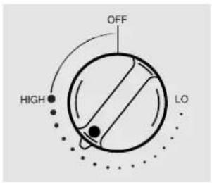
OFF HIGH LOHow to Light a Burner
Your cooktop burners are lit by electric ignition, eliminating the need for standing pilot lights with constantly burning flames.
The igniters make clicking sounds and spark even when only a single burner is being turned on. Do not touch any of the burners when the igniters are clicking.
Push the control knob in and turn it counterclockwise to the desired position from HIGH to LO. After the burner ignites, turn the knob in either direction to adjust the flame size. To turn a burner off, turn the knob clockwise as far as it will go, to the OFF position.
In case of a power failure, you can light the burners with a match. Hold a lit match to the burner, then push in and turn the control knob to the HIGH position. Use extreme caution when lighting burners this way. Burners in use when an electrical power failure occurs will continue to operate normally.
Do not operate a burner for an extended period of time without cookware on the grate. The finish on the grate may chip without cookware to absorb the heat.
- Check to be sure the burner you turn on is the one you want to use.
- Be sure the burners and grates are cool before you place your hand, a pot holder, cleaning cloths or other materials on them.
Simmer and Power Burners
The right rear burner is best for smaller pans and cooking operations requiring carefully controlled simmering conditions.
The front right burner is the high power burner for larger pans and fast boiling operations.
natural_image
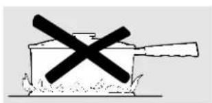
Simple line drawing of a cooking pot with a crossed-out black X mark (no text or symbols)How to Select Flame Size
For safe handling of cookware, never let the flames extend up the sides of the cookware.
Watch the flame, not the knob, as you reduce heat. The flame size on a gas burner should match the cookware you are using.
Any flame larger than the bottom of the cookware is wasted and only serves to heat the handle.
Using your cooktop
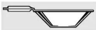
Use a flat-bottomed wok.
Wok This Way
We recommend that you use a flat-bottomed wok, available at your local retail stores, or use the Wok Holder accessory with traditional round bottomed woks. The Wok Holder accessory, model JXWK, can be ordered from your appliance dealer.
The Wok Holder fits on top of the cooktop grate to provide support and proper air circulation for traditional round bottom woks only. Do not use flat bottomed woks with the Wok Holder.
Do not use a wok on any other support ring. Placing the ring over the burner grate may cause the burner to work improperly, resulting in carbon monoxide levels above allowable current standards. This could be dangerous to your health. Do not try to use such woks without the ring unless you are using the Wok Holder. You could be seriously burned if the wok tipped over.
Cookware
Aluminum: Medium-weight cookware is recommended because it heats quickly and evenly. Most foods brown evenly in an aluminum skillet. Use saucepans with tight fitting lids when cooking with minimum amounts of water.
Enamelware: Under some conditions, the enamel of some cookware may melt. Follow cookware manufacturer's recommendations for cooking methods.
Glass: There are two types of glass cookware: those for oven use only and those for cooktop cooking (saucepans, coffee and tea pots). Glass conducts heat very slowly.
Cast Iron: If heated slowly, most skillets will give satisfactory results.
Heatproof Glass Ceramic: Can be used for either surface or oven cooking. It conducts heat very slowly and cools very slowly. Check cookware manufacturer's directions to be sure it can be used on a gas cooktop.
Stainless Steel: This metal alone has poor heating properties and is usually combined with copper, aluminum or other metals for improved heat distribution. Combination metal skillets usually work satisfactorily if they are used with medium heat as the manufacturer recommends.

natural_image
Pure mechanical cross symbol without any text or labelsStove Top Grills
Do not use stove top grills on your sealed gas burners. If you use the stove top grill on the sealed gas burner it will cause incomplete combustion and can result in exposure to carbon monoxide levels above allowable current standards. This can be hazardous to your health.
Cooktop vent system.
The built-in vent system helps remove cooking vapors, odors and smoke from foods prepared on the cooktop.
Continuous use of the vent system helps keep the kitchen comfortable
and less humid, reducing cooking odors and soiling moisture that normally creates a frequent need for cleaning.
text_image
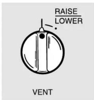
RAISE LOWER VENTRaising or Lowering the Vent
To raise the vent, turn the VENT knob to the RAISE/LOWER position. The vent will rise to the fully extended position. There is no intermediate position.
To lower the vent, turn the VENT knob again to the RAISE/LOWER position. The vent will then descend.
The vent fan will only operate in the fully extended position.
text_image
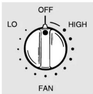
OFF LO HIGH FANHow to Operate the Vent System
Turn the FAN knob to the HIGH position to turn it on.
If you continue turning the FAN knob, you can select a fan speed between HIGH and LO.
The FAN knob does not have to be turned to OFF before the vent is lowered. The fan will automatically turn off when the vent is lowered.
If the fan was not turned off when the vent was lowered, it will automatically come on at the previously selected speed when the vent is fully raised.
natural_image
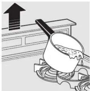
Illustration of a cooking pot on a stove with an upward arrow indicating increase (no text or symbols)CAUTION: Be careful when raising or lowering the vent. Be sure pots, pot handles and other objects are clear of the vent cover and cannot be struck or tipped by the vent being raised. Keep hands and fingers away from all vent parts.
Care and cleaning of the cooktop.
Be sure electrical power is off and all surfaces are cool before cleaning any part of the cooktop.
Glass Cooktop
To keep the cooktop looking its best, wipe up any spills as they occur. This will keep them from burning on and becoming more difficult to remove.
As soon as the cooktop is cool, wash the glass surface with a cloth moistened with warm, soapy water; rinse with clean water, and dry with a soft cloth. You can use any liquid household detergent.
Do not use abrasive materials such as metal pads, cleansing powder and scouring pads—they may scratch the surface.
Do not use harsh chemicals such as bleach or chemical oven cleaners.
CAUTION: Do not cook on or clean a broken or cracked cooktop. Cleaning solutions and spillovers penetrating the cooktop can create a risk of electric shock. Call for a service technician immediately.

natural_image
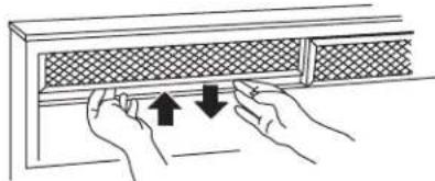
Three-step diagram showing hand positioning of a mesh panel with arrows indicating movement (no text or symbols)Grease Filters
The efficiency of your downdraft depends on a clean filter. Frequency of cleaning depends on the type of cooking you do. Grease filters should be cleaned at least once a month. Never operate the downdraft without the filters in place.
To remove: Lift up and pull the bottom out. Remove the left filter first, then slide the right filter to the left and remove it.
To clean: Soak and then agitate in a hot detergent solution. Light brushing may be used to remove imbedded soil. Rinse, shake and remove moisture
before replacing. Filters may be cleaned by placing in dishwasher, although some slight color fading may occur after several washings.
With careful handling, the filter will last for years. If replacement becomes necessary, order the part from your dealer.
Control Knobs
Clean up spatters with a damp cloth. Remove heavier soil with warm, soapy water.
Do not use abrasives of any kind on the control panel.
The control knobs may be removed for easier cleaning. To remove a knob, pull it straight off the stem. Wash the knobs in soap and water but do not soak.

text_image
Burner Grate Burner Cap Burner Head Burner BowlSealed Burner Assemblies
Turn all controls OFF before removing the burner parts.
The burner grates, caps and burner heads can be lifted off, making them easy to clean.
CAUTION: Do not operate the burner without all burner parts in place.

The electrode of the spark igniter is exposed when the burner head is removed. When one burner is turned to LITE, all the burners spark. Do not attempt to disassemble or clean around any burner while another burner is on. An electric shock may result, which could cause you to knock over hot cookware.
natural_image
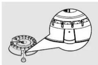
Technical line drawing of a mechanical device with gears and a spherical housing (no text or symbols)Use a sewing needle or twist-tie to unclog the small hole in the burner head. After cleaning, make sure the slot in the burner head is positioned over the electrode.
Burner Heads
NOTE: Before removing the burner heads and caps, remember their size and location. Replace them in the same location after cleaning.
For proper ignition, make sure the small hole in the section that fits over the electrode is kept open. A sewing needle or wire twist-tie works well to unclog it.
The slits in the burner heads of your cooktop must be kept clean at all times for an even, unhampered flame.
You should clean the surface burners routinely, especially after bad spillovers, which could clog these openings.
To remove burned-on food, soak the burner heads in a solution of mild liquid detergent and hot water for 20-30 minutes. For more stubborn stains, use a toothbrush.
Before putting the burner head back, shake out excess water and then dry it thoroughly by setting it in a warm oven for 30 minutes.
Replace the burner heads and caps. Make sure that the heads and caps are replaced in the correct location. There are 2 medium, one large and one small head and cap.

text_image
Medium Head Medium Head Small Head Large HeadFront of Cooktop
text_image
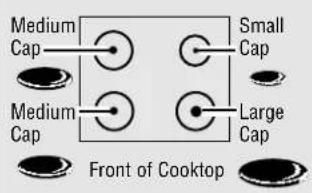
Medium Cap Small Cap Medium Cap Large Cap Front of CooktopBurner Caps
Lift off when cool. Wash burner caps in hot, soapy water and rinse with clean water. You may scour with a plastic scouring pad to remove burned-on food particles.
Dry them in a warm oven or with a cloth—don't reassemble them wet. Replace the burner caps.
Make sure that caps are replaced on the correct size burner. There are 2 medium, one large and one small head and cap.
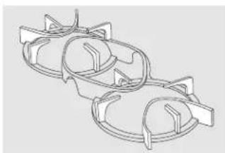
natural_image
Technical line drawing of two symmetrical mechanical components with mounting brackets (no text or symbols)Burner Grates
Cast-iron burner grates should be washed regularly and, of course, after spillovers.
Wash them in hot, soapy water and rinse with clean water. Dry the grates with a cloth—don't put them back on the cooktop wet. When replacing the grates, be sure they're positioned securely over the burners.
To get rid of burned-on food, place the grates in a covered container or plastic bag. Add 1/4 cup ammonia and let them soak for 30 minutes. Wash, rinse well, and dry.
To prevent rusting, apply a light coating of cooking oil on the bottom of the grates.
Although they're durable, the grates will gradually lose their shine, regardless of the best care you can give them. This is due to their continual exposure to high temperatures.
Do not operate a burner for an extended period of time without cookware on the grate. The finish on the grate may chip without cookware to absorb the heat.
BEFORE YOU BEGIN
Read these instructions completely and carefully.
Save these instructions for local inspector's use.
IMPORTANT-OBSERVE ALL GOVERNING CODES AND ORDINANCES.
Note to Installer: Be sure to leave these instructions with the consumer.
FOR YOUR SAFETY
If You Smell Gas:
- Open windows.
- Don't touch any electrical switches.
- Extinguish any open flame.
- Immediately call your gas supplier.
Do not store or use gasoline or other flammable vapors and liquids in the vicinity of this or any other appliance.
Parts List
Cooktop
■ 2 twin burner grates
■ 4 burner caps (1 small, 2 medium, 1 large)
■ Gas pressure regulator with attached 1/2" to 3/8" reducing bushing and 3/8" pipe nipple
■ 2 clamping brackets with screws
■ Attached 120 volt grounded plug cord
■ Self adhesive gasket
1/4" x 36" (1)
3/16" x 36" (2)
Downdraft and Blower Unit
JXBA56 motor and blower assembly is required for both models.
The blower/motor assembly can be located below the cabinet floor. The assembly will fit between 16" floor joists. Order JXRB57 for indoor remote locations.
- In this installation a transition to 6'' round is required.
■ The blower motor assembly can also be installed outdoors. Order JXBC57 for remote blower installation outdoors.
■ Downdraft unit
■ Downdraft stability brackets
■ Two filters
Tools and Parts Needed
■ Large flat blade screwdriver
Saw
Carpenter's square
■ Pipe wrench
■ Manual gas line shut-off valve
■ Pipe joint sealant that resists action of LP gas
■ Ductwork to suit the installation
For flexible connection where local codes permit:
■ Flexible metal tubing (same 3/4" or 1/2" I.D. as gas supply line)
■ Flare union adapter for connection to supply line (3/4" NPT x 3/4" I.D. or 1/2" NPT x 1/2" I.D.)
■ Flare union adapter for connection to regulator (1/2" NPT x 3/4" I.D. or 1/2" I.D.)
For rigid connection:
■ Pipe fittings as required
IMPORTANT SAFETY INSTRUCTIONS
The cooktop has been design certified by the American Gas Association. As with any appliance using gas and generating heat, there are certain safety precautions you should follow. You'll find these precautions in this Owner's Manual; read it carefully.
■ Be sure your cooktop is installed properly by a qualified installer or service technician.
The cooktop must be electrically grounded in accordance with local codes, or in their absence, with the National Electrical Code ANSI/NFPA No. 70-Latest Edition.
■ Installation of this cooktop must conform with local codes, or in the absence of local codes, with the National Fuel Gas Code ANSI Z223.1-Latest Edition.
■ Disconnect electrical supply before servicing.
■ Make sure the wall coverings around the cooktop can withstand heat generated by the cooktop up to 200^ F.
- Avoid placing cabinets above the cooktop.
If cabinets are placed above the cooktop, allow a minimum clearance of 30" between the cooking surface and the bottom of unprotected cabinets.
If cabinets are placed above the cooktop, use cabinets no more than 13" deep.
If a 30" clearance between cooking surface and overhead combustible material or metal cabinets cannot be maintained, protect the underside of the cabinets above the cooktop with not less than 1/4" insulating millboard or gypsum board at least 3/16" thick covered with 28 gauge sheet steel or 0.020" thick copper.
- Clearance between the cooking surface and protected cabinets MUST NEVER BE LESS THAN 24". The vertical distance from the plane of the cooking surface to the bottom of adjacent overhead cabinets extending closer than 1" to the plane of the cooktop sides must not be less than 18".
Dimensions and Clearances
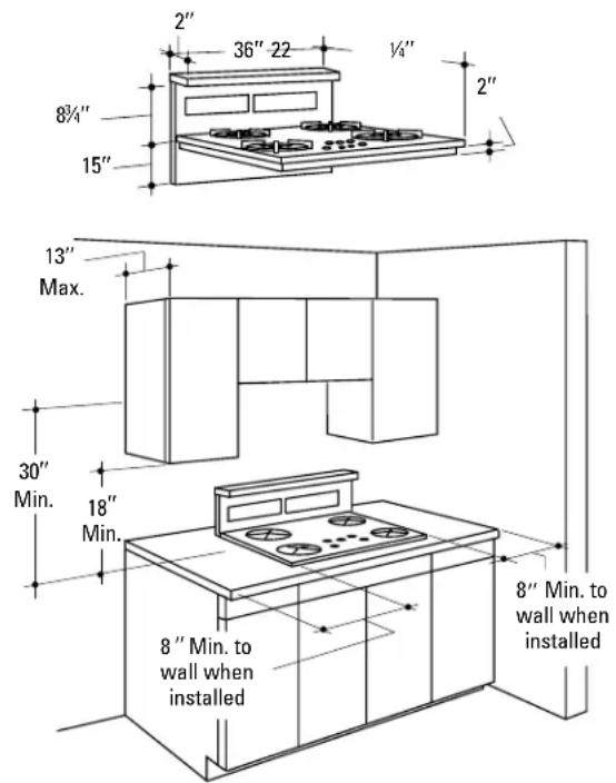
text_image
2" 36" 22 1/4" 8¾" 15" 2" 13" Max. 30" Min. 18" Min. 8" Min. to wall when installed 8" Min. to wall when installedThe downdraft system with blower, motor and ductwork will occupy the cabinet below the cooktop. Drawers cannot be installed below this cooktop.
Avoid placing cabinets above the cooktop unit, if possible, in order to reduce the hazards caused by reaching over heated surface units.
If the cabinetry is used above the cooktop, allow a minimum 30" clearance between the cooking surface and the bottom of the unprotected cabinet.
If the clearance between the cooktop and the cabinetry is less than 30", the cabinet bottom must be protected with a flame retardant millboard at least 1/4" thick, or gypsum board at least 3/16" thick, covered with 28 gauge sheet steel or 0.020" thick copper. Clearance between the cooktop and the protected cabinetry MUST NEVER BE LESS THAN 24".
EXCEPTION: Installation of a listed microwave oven or cooking appliance over the cooktop shall conform to the installation instructions packed with that appliance.
Working areas adjacent to the cooktop should have an 18" minimum clearance between the countertop and the bottom of the cabinet. If the clearance is less than 18", the adjacent cabinets should be at least 8" from the side of the cooktop.
Preparing the Countertop
Back of countertop
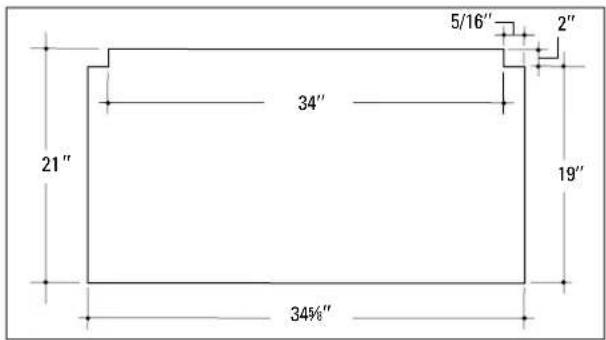
text_image
5/16" 2" 34" 21" 19" 34½"Front of countertop
Countertop cut-out dimensions
Cut out the opening as shown in the diagram. Measure carefully when cutting the countertop. Make sure the sides of the opening are parallel and the front and rear cuts are exactly perpendicular to the sides.
The front of the opening must clear the front support rail on the cabinet and the rear of the opening must clear the rear support of the cabinet.
Cut the Opening
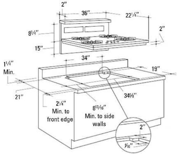
text_image
2" 36" 22¼" 8¾" 15" 34" 1½" Min. 21" 2¼" Min. to front edge 8¼/₁₆" Min. to side walls 34¾" 2" ½" 16"Measure carefully when cutting countertop. Make sure sides of opening are parallel and rear and front cuts are exactly perpendicular to sides.
The gas downdraft cooktop is designed to fit in a 36" or larger base cabinet.
The countertop cutout for the cooktop must be:
■ 34 ^5/8 " at the front of the counter and 34" at the back
■ 19" front to back notch
■ 21" front to back of cutout
The notches at the back of the cutout are:
■ 2" forward and 5/16" to the inside.
Follow the illustration shown.
- Allow at least 1 14 clearance between back of cutout and wall.
- Allow at least 8^13/16 clearance from right and left sides of cutout to adjacent wall.
- Allow at least 2 14'' clearance between front of cutout and front edge of countertop.
CAUTION: Wall coverings, countertops and cabinets should be able to withstand 200°F. heat generated by the cooktop.
Read these instructions completely and carefully.
Venting Options
Side to side adjustments:
The entire blower mounting plate can be adjusted 3½" to the left or right. This will help to align vent discharge to house ductwork.
30° Rotation
For even more flexibility, the entire blower can be rotated up to 30^ towards the left or 30^ towards the right.
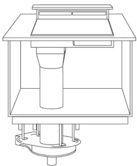
Discharge direction:
The blower assembly may be removed and turned 90^ for a left or right side discharge.
■ The downdraft vent is shipped with the discharge outlet pointing straight down and can be changed to the left or right side.
A left or right 90° direction adjustment should be performed before dropping into the countertop opening.
■ Flatten the shipping box to use as a pad.
■ Lay the vent on its back onto the pad.
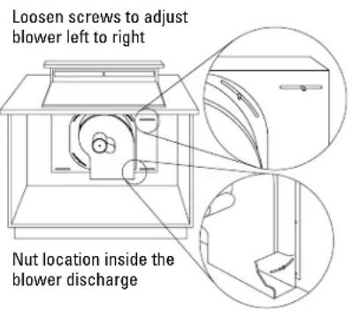
To change to a left or right discharge:
☐ Remove 4 nuts holding the blower to the mounting plate. See illustration. One nut is just inside the blower discharge.
Remove and turn the blower to the right or left.
e Reinstall the 4 nuts.
To locate the ductwork holes in the cabinet floor or side walls:
☐ Temporarily, place vent into the countertop opening.
b Push the vent all the way to the back of the opening.
If you are transitioning to 6" round, place transition piece over the discharge outlet.
- Mark the location and remove the assembly.
- Cut holes and install ductwork connections.
Order JXRB57 for installation of the blower and motor below the floor.
Order JXBC57 for installation of the blower and motor outdoors.
text_image
Loosen screws to adjust blower left to right Nut location inside the blower discharge
text_image
30° rotation left or right
text_image
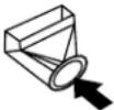
Discharge down (as supplied)
text_image
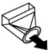
Discharge right
natural_image
Diagram of a device inside a container with a circular component, labeled 'Discharge left' (no other text or symbols)Optional Kits
natural_image
Technical line drawing of a mechanical assembly with a cylindrical component mounted on a base (no text or symbols)JXRB57 optional accessory for indoor remote location of the blower/motor assembly. Use this kit when the blower and motor assembly will be located outside or below the cabinet floor.

natural_image
Technical line drawing of a mechanical or electrical component assembly (no text or symbols)JXBC57 optional outdoor cover accessory for remote installation of blower and motor assembly on an outside wall.
Duct Fittings
Use the chart at the right to compute maximum permissible lengths for duct runs to outdoors.
NOTE: Do not exceed maximum permissible equivalent lengths!
Flexible ducting:
If flexible metal ducting is used, all the equivalent feet values in the table should be doubled. The flexible metal duct should be straight and smooth and extended as much as possible.
Do NOT use flexible plastic ducting.
NOTE: Any home ventilation system, such as a cooktop with a downdraft exhaust mechanism, may interrupt the proper flow of combustion air and exhaust required by fireplaces, gas furnaces, gas water heaters and other naturally vented systems. To minimize the chance of interruption of such naturally vented systems, follow the heating equipment manufacturer's guidelines and safety standards such as those published by NFPA and ASHRAE.
| Duct Pieces Length* Used Length | Equivalent Number Equivalent | Total | ||
 | 6" round, (per foot straight length) feet | 1 ft. | ||
 | 3/4" x 10" straight length) feet | 1 ft.(per foot) | ||
 | 6", 90° elbow 15 ft. | |||
 | 6", 45° elbow 9 ft. | |||
 | 3/4" x 10" 90° elbow 16 ft. | |||
 | 31⁄4" x 10" 45° elbow 5 ft. | |||
 | 31⁄4" x 10" 90° flat elbow 18 ft. | |||
 | 6" round to 31⁄4" x 10" transition 7 ft. | |||
 | 31⁄4" x 10" to 6" round transition 5 ft. | |||
 | 6" round to 31⁄4" x 10" transition 90° elbow 20 ft. | |||
 | 31⁄4" x 10" to 6" round transition 90° elbow 12 ft. | |||
 | 6" round wall cap with damper | 21 ft. | ||
 | 31⁄4" x 10" wall cap with damper | 27 ft. | ||
| [SAXZ] | 6" round roof cap 20 ft. | |||
 | 6" round roof vent 24 ft. | |||
| Total duct run should not exceed 150 ft. | ||||
| *Actual length of straight duct plus duct fitting equivalent. Equivalent length of duct pieces are based on actual tests conducted by GE Evaluation Engineering and reflect requirements for good venting performance with any downdraft cooktop. | ||||
Power Supply Locations
Gas Supply:
These cooktops are designed to operate on natural gas at 4" of water column pressure or on LP gas at 10" of water column pressure.
These cooktops are shipped from the factory set for natural gas. If you decide to use this cooktop with LP gas, conversion adjustments must be made by a service technician or other qualified person. Order JXLP56 Conversion Kit.
The pressure regulator must be connected in series with the manifold of the cooktop and must remain in series with the supply line regardless of type of gas being used.
For proper operation, the maximum inlet pressure to the regulator must be no more than 10" water column pressure for natural gas and 14" water column pressure for LP gas.
- When checking the regulator, the inlet pressure must be at least 1" greater than the regulator output setting.
If the regulator is set for 4" of water column pressure, the inlet pressure must be at least 5".
If the regulator is set for 10" of water column pressure, the inlet pressure must be at least 11".
For ease of installation, and if local codes permit, the gas supply line into the cooktop should be 1/2" or 3/4" ID flexible metal appliance connector, three to five feet long.
NOTE: Purchase a new flexible line. DO NOT USE AN OLD PREVIOUSLY USED LINE.
■ Make gas connection through rear wall, or on cabinet floor at rear, as illustrated.
Electrical Supply:
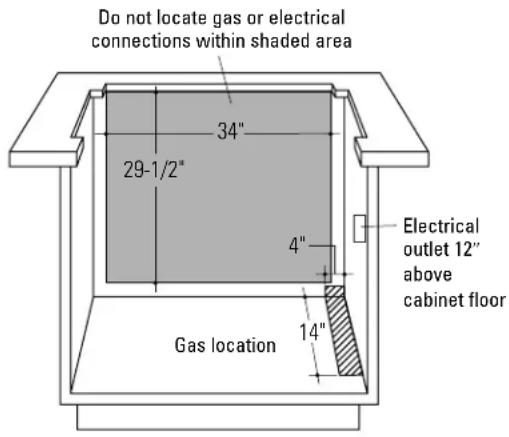
text_image
Do not locate gas or electrical connections within shaded area 34" 29-1/2" 4" Electrical outlet 12" above cabinet floor Gas location 14"The built-in gas downdraft cooktop features pilotless electric ignition for energy savings and reliability. It operates on a 120 volt, 60 Hz power supply. A separate circuit, protected by a 15 amp time delay fuse or circuit breaker, is required.
A properly grounded 3-prong receptacle should be located within reach of cooktop's four foot power cord.
IMPORTANT: (Please read carefully.) FOR PERSONAL SAFETY, THIS APPLIANCE MUST BE PROPERLY GROUNDED.
The power cord of this appliance is equipped with a three-prong (grounding) plug which mates with a standard three-prong grounding wall receptacle to minimize the possibility of electric shock hazard from this appliance. The customer should have the wall receptacle and circuit checked by a qualified electrician to make sure the receptacle is properly grounded and has correct polarity.
Where a standard two-prong wall receptacle is encountered, it is the personal responsibility and obligation of the customer to have it replaced with a properly grounded three-prong wall receptacle.
Do Not, Under Any Circumstances, Cut Or Remove The Third (ground) Prong From The Power Cord.
Do not use an extension cord.
Step 1
Install Downdraft Vent
Place the downdraft vent into the countertop cutout, against the back side.
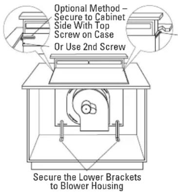
text_image
Optional Method - Secure to Cabinet Side With Top Screw on Case Or Use 2nd Screw Secure the Lower Brackets to Blower HousingPreferred Method – Secure the Upper Brackets With Screws Located on the side of Case and Attach to Back Wall of Cabinet
Place the downdraft vent into the countertop cutout, against the back side.
- Secure the downdraft to the countertop supplied brackets. See illustration.
-Fasten brackets to top screws on the front side of the vent, secure to cabinet side wall just below the countertop. Or,
-Fasten one bracket to vent side and secure to cabinet back wall.
-Install two brackets on the bottom of the vent.
Attach brackets to slide screws on the vent and to the floor using wood screws (not supplied).
- When installing in a tile countertop surface, it may be necessary to apply a locally approved caulking to cover any gaps.
Step 2
Install the Ductwork
Use minimum 26 gauge galvanized or 24 gauge aluminum duct in 6" round or 3¼" x 10" size, or a combination of both. PVC duct should be used if installing under a poured concrete slab. DO NOT use flexible plastic ducting.
■ Always use an appropriate roof or wall cap with damper. Laundry type wall caps should never be used.
■ Use the straightest duct run possible.
For satisfactory performance the duct run should not exceed 150 ft. or its equivalent length if bends or other various fittings are used. Refer to table of equivalent lengths for various duct configurations.

text_image
Air flow Duct tape over seam and screw Screw■ Install ductwork so that the piece of duct nearest the downdraft unit slots INTO the next piece of the duct. Secure the joints with self-tapping screws and apply duct tape around the joints to ensure an airtight seal.
(continued on next page)
Step 3
Install the Pressure Regulator
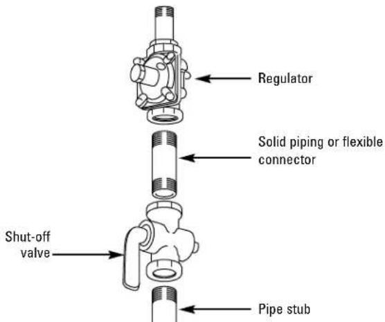
text_image
Regulator Solid piping or flexible connector Shut-off valve Pipe stub■ Install the supplied pressure regulator and nipple in the gas line as close to the cooktop inlet as possible. Allowances for ventilation ducting may be necessary.
Make sure the regulator is installed in the right direction.
■ Install a manual shut-off valve in the gas line in an easily accessible location.
NOTE: Instead of using solid piping to connect to pressure regulator, an approved flexible metal appliance connector may be used between the pipe stub and the shut-off valve and the pressure regulator, if local codes permit.
Appropriate flare nuts and adapters are required at each end of the flexible connector.
■ Turn on the gas. Check for leaks using a liquid leak detector at all joints in the system. (The pressure test nipple is adjacent to the gas inlet pipe on the rear right hand side of the cooktop bottom.)
CAUTION: DO NOT USE A FLAME TO CHECK FOR GAS LEAKS.
IMPORTANT: Disconnect the cooktop and the individual shut-off valve from the gas supply piping system during any pressure testing of that system at test pressures greater than 1/2 psig. Isolate the cooktop from the gas supply piping system by closing the individual manual shut-off valve to the cooktop during any pressure testing of the gas supply piping system at test pressures equal to or less than 1/2 psig.
Step 4
Install the Cooktop
NOTE: If the cooktop is installed into a 36" base cabinet, the pressure regulator MUST BE installed to the bottom of the cooktop before the cooktop is placed into the cabinet.
■ Remove packaging from the cooktop.

natural_image
Line drawing of a hand pressing down on a four-cylindrical stove (no text or symbols)To insure a good fit, position the cooktop over the cutout opening and carefully lower into place. Check edges all the way around to be sure all cutout edges are concealed and there are no gaps.
■ Carefully lift and remove the cooktop.
Step 4
Install the Cooktop (continued)
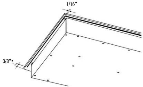
text_image
1/16" 3/8"- Cut a 3/16" gasket strip in half. Peel off the backing and apply to the underside of the glass cooktop edge, on each side at least 3/8" from the back and as close to the edge as possible without protruding.
■ Apply the other gasket strip to the underside of the glass at the front of the cooktop.
■ Remove remaining adhesive backing.
■ Position the cooktop over the opening, making sure that the power cord is dropped into the cabinet.
■ Lower the cooktop into the cutout, pressing gently and evenly to seat.
NOTE: If the cooktop is installed in a 36" base cabinet, the mounting brackets cannot be used because of interference with the cabinet sides. In this case, the cooktop can be secured to the cabinet with angle brackets (not supplied).
Remove one screw at the bottom of the cooktop body on both sides and secure the bracket with those screws. Then, secure the brackets to the cabinet sides.
■ Insert hold-down bracket into highest slots on the right and left sides of the cooktop.
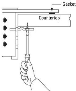
text_image
Gasket CountertopCooktop has three slots, the highest available will depend on the thickness of the countertop.
- Secure the brackets to the underside of the countertop with screws provided.
Step 5
Electrical Connections
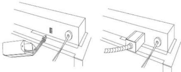
natural_image
Technical line drawings of mechanical components with no visible text or symbols■ Connect the 3-pin plastic plug from the blower/motor assembly to the 3-pin plastic socket on the underside of the vent, next to the conduit.
■ Slide the metal cover over the connection and secure with screws.

text_image
Service plate Electrical supply cord 6-Pin plug Metal cover Electrical 6-pin socket Pressure regulator■ Connect the 6-pin plastic plug from the downdraft assembly to the 6-pin plastic socket on the underside of the cooktop, next to the power cord.
■ Slide the metal cover over the connection and secure with screws.
Step 6
Connect Power
Plug power cord into properly grounded receptacle.
Step 7
Assemble Burners, Check Ignition
Assemble burner as shown.

text_image
Burner Grate Burner Cap Burner Head Burner BowlPlace the burner heads and caps on the burners. Make sure that the heads and caps are placed on the correct size burner. There is one small, 2 medium and one large head and cap.

text_image
Medium Head and Cap Small Head and Cap Medium Head and Cap Front of Cooktop Large Head and Cap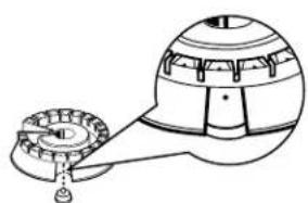
natural_image
Diagram of a mechanical device with gears and a handle, no text or symbols presentMake sure the slot in the burner head is positioned over the electrode.
Check for proper ignition:
■ Push in one control knob and turn 90° to HIGH position.
■ The igniter will spark and the burner will light; the igniter will cease sparking when the burner is lit.
■ First test may require some time, while air is flushed out of the gas line.
■ Turn knob to OFF.
■ Repeat the procedure for each burner.
Step 8
Install Filters, Check Operation of Downdraft
To raise the vent, turn the VENT knob to RAISE/LOWER.
- Hold the knob until the vent begins to rise. The vent will automatically stop when it is fully extended.
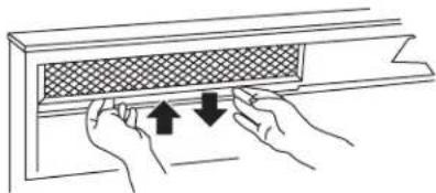
natural_image
Illustration of hands installing or adjusting a window panel with arrows indicating movement (no text or symbols)Tip filter into the opening and pull straight down so that the filter rests on slides.

natural_image
Line drawing of hands installing a window with a grid pattern (no text or symbols)■ Slide the filter to the right side.
natural_image
Illustration of hands installing or adjusting a window panel with arrows indicating direction (no text or symbols)■ Tip the other filter into the opening and pull straight down.
■ To turn the fan on, turn the FAN knob to HIGH. Continue turning the FAN knob to select a fan speed between HIGH and LO.
NOTE: It is not necessary to turn the fan OFF before lowering the vent. The fan will automatically turn off when the vent is lowered. When the fan is not turned off before lowering the vent, it will automatically come on at the previously selected speed when the vent is fully raised.
To lower the vent, turn the VENT knob to RAISE/LOWER. Hold the knob until the vent begins to lower.
Before You Call For Service...

Troubleshooting Tips Save time and money! Review the chart on this page first and you may not need to call for service.
| Problem Possible Causes What To Do | ||
| Burners have yellow or yellow-tipped flames | The combustion quality of burner flames needs to be flames are normal. If burner flames look like determined visually, service. Normal burner flames should look like depending on the type of gas you use. With LP gas, some yellow tipping on outer cones is normal. | • Use the illustrations below to determine if your burner A, call for B or C, depending on the type of gas you use. With LP gas, some yellow tipping on outer cones is normal. |
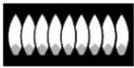 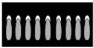  | ||
| A-Yellow flames B-Yellow tips C-Soft blue flames Call for service on outer cones Normal for natural Normal for LP gas gas | ||
| Burner parts not replaced correctly. | • See Care and cleaning of the cooktop section. | |
| Control knobs will not turn | Controls improperly set. | • To turn from the OFF position, push the knob in and then turn. The knob can only be turned in a counterclockwise direction. When the knob is at any other position, it can be turned in either direction without being pushed in. |
| Burners do not light | Plug on cooktop is not completely inserted in the electrical outlet. | • Make sure electrical plug is plugged into a live, properly grounded outlet. |
| Gas supply not connected or turned on. | • See the Installation Instructions section. | |
| A fuse in your home may be blown or the circuit breaker tripped. | • Replace the fuse or reset the circuit breaker. | |
| Igniter orifice in burner body may be clogged. | • Remove the obstruction. | |
| Burner parts not replaced correctly. | • See the Care and cleaning of the cooktop section. | |
| Hole in burner top behind the igniter may be clogged. | • Use a small sewing needle to unplug. | |
| Ticking sound persists after burner is turned off | Be sure the knob is in the OFF position. | • Remove knob by pulling it straight off the stem and check the bottom of the knob for any build-up of soil. |
| Burner flames very large or yellow | Improper air to gas ratio. | • If cooktop is connected to LP gas, contact the person who installed your cooktop or made the conversion. |
| Fan does not work | The vent is not fully extended. | • See the Installation Instructions section. |
| The fan control knob is improperly set. | • Turn knob in clockwise direction to turn fan on. | |
Notes
| Safety Instructions Operating Instructions Care and Cleaning Troubleshooting Tips Customer Service |
Notes
GE Service Protection Plus™
GE, a name recognized worldwide for quality and dependability, offers you Service Protection Plus™—comprehensive protection on all your appliances—No Matter What Brand!
Benefits Include:
- Backed by GE
- All brands covered
• Unlimited service calls - All parts and labor costs included
- No out-of-pocket expenses
• No hidden deductibles
• One 800 number to call
We'll Cover Any Appliance. Anywhere. Anytime.\*
You will be completely satisfied with our service protection or you may request your money back on the remaining value of your contract. No questions asked. It's that simple.
Protect your refrigerator, dishwasher, washer and dryer, range, TV, VCR and much more—any brand! Plus there's no extra charge for emergency service and low monthly financing is available. Even icemaker coverage and food spoilage protection is offered. You can rest easy, knowing that all your valuable household products are protected against expensive repairs.
Place your confidence in GE and call us in the U.S. toll-free at 800-626-2224 for more information.
*All brands covered, up to 20 years old, in the continental U.S.

Cut here
Please place in envelope and mail to:
General Electric Company
Warranty Registration Department
P.O. Box 32150
Louisville, KY 40232-2150
Consumer Product Ownership Registration
Dear Customer:
Thank you for purchasing our product and thank you for placing your confidence in us.
We are proud to have you as a customer!
Follow these three steps to protect your new appliance investment:
1
Complete and mail
your Consumer
Product Ownership
Registration today.
Have the peace of
mind of knowing we
can contact you in the
unlikely event of a
safety modification.
2
After mailing the
registration below,
store this document
in a safe place. It
contains information
you will need should
you require service.
Our service number is
800 GE CARES
(800-432-2737).
3
Read your Owner's
Manual carefully.
It will help you
operate your new
appliance properly.
If you have questions,
or need more
information, call the
GE Answer Center®
800.626.2000.
Model Number Serial Number

natural_image
Two identical horizontal lines with tick marks, no text or symbols presentImportant: If you did not get a registration card with your product, detach and return the form below to ensure that your product is registered, or register online at www.geappliances.com.
Consumer Product Ownership Registration

Model Number Serial Number

natural_image
Two identical horizontal lines with tick marks, no text or symbols presentMr. □ Ms. □ Mrs. □ Miss □
First Name
Last Name
Street Address
Apt.#
E-mail Address
City State Zip Code
Date Placed
In Use Month
(No text)
Day
Year
Phone Number
Occasionally, we may allow selected companies to send you information.
□ Check here if you do not want this information.

GE Appliances
General Electric Company
Louisville, Kentucky
www.geappliances.com
GE Gas Cooktop Warranty

All warranty service provided by our Factory Service Centers or an authorized Customer Care® technician. For service, call 800-GE-CARES.
For The Period Of: GE Will Replace, At No Charge To You:
One Year Any part From the date of the original purchase
of the cooktop which fails due to a defect in materials or workmanship. During this full one-year warranty, GE will also provide, free of charge, all labor and in-home service to replace the defective part.
What GE Will Not Cover:
■ Service trips to your home to teach you how to use the product.
■ Improper installation.
- Failure of the product if it is abused, misused, or used for other than the intended purpose or used commercially.
■ Replacement of house fuses or resetting of circuit breakers.
■ Damage to the product caused by accident, fire, floods or acts of God.
■ Incidental or consequential damage to personal property caused by possible defects with this appliance.
This warranty is extended to the original purchaser and any succeeding owner for products purchased for home use within the USA. In Alaska, the warranty excludes the cost of shipping or service calls to your home.
Some states do not allow the exclusion or limitation of incidental or consequential damages. This warranty gives you specific legal rights, and you may also have other rights which vary from state to state. To know what your legal rights are, consult your local or state consumer affairs office or your state's Attorney General.
Warrantor: General Electric Company. Louisville, KY 40225
Service Telephone Numbers.
GE Answer Center ^® 800.626.2000
The GE Answer Center ^® is open 24 hours a day, 7 days a week.
OR
Visit our Website at: www.geappliances.com
In-Home Repair Service 800-GE-CARES (800-432-2737)
Expert GE repair service is only a phone call away.
Special Needs Service 800.626.2000
800-TDD-GEAC (800-833-4322)
GE offers, free of charge, a brochure to assist in planning a barrier-free kitchen for persons with limited mobility.
Service Contracts 800-626-2224
Purchase a GE service contract while your warranty is still in effect and you'll receive a substantial discount. GE Consumer Service will still be there after your warranty expires.

Parts and Accessories 800-626-2002
Individuals qualified to service their own appliances can have parts or accessories sent directly to their homes (VISA, MasterCard and Discover cards are accepted).
Instructions contained in this manual cover procedures to be performed by any user. Other servicing generally should be referred to qualified service personnel. Caution must be exercised, since improper servicing may cause unsafe operation.

Service Satisfaction
If you are not satisfied with the service you receive from GE:
First, contact the people who serviced your appliance.
Next, if you are still not pleased, write all the details—including your phone number—to:
Manager, Customer Relations
GE Appliances
Appliance Park
Louisville, KY 40225