ZGU365DBBBG - Cooker GE - Free user manual and instructions
Find the device manual for free ZGU365DBBBG GE in PDF.

User questions about ZGU365DBBBG GE
0 question about this device. Answer the ones you know or ask your own.
Ask a new question about this device
Download the instructions for your Cooker in PDF format for free! Find your manual ZGU365DBBBG - GE and take your electronic device back in hand. On this page are published all the documents necessary for the use of your device. ZGU365DBBBG by GE.
USER MANUAL ZGU365DBBBG GE
Before you begin—Read these instructions completely and carefully.
IMPORTANT: Save these instructions for local inspector's use.
IMPORTANT: OBSERVE ALL GOVERNING CODES AND ORDINANCES.
NOTE TO INSTALLER: Be sure to leave these instructions with the Consumer.
NOTE TO CONSUMER: Keep these instructions with your Owners Manual for future reference.
WARNING This appliance must be properly grounded. See “Power Supply”, page 8.
If you have a question concerning the installation of this product, call the GE Answer Center® Consumer Information Service at 800.626.2000, 24 hours a day, 7 days a week. If you received a damaged cooktop, you should immediately contact your dealer or builder.
Proper installation is the responsibility of the installer. Product failure due to improper installation is not covered under the GE Appliance Warranty. See the Owners Manual for warranty information.
For Monogram local service in your area, 1-800-444-1845.
For Monogram service in Canada, 1-888-880-3030.
For Monogram Parts and Accessories, call 1-800-626-2002.
FOR YOUR SAFETY
If you smell gas:
- Open windows.
- Don't touch electrical switches.
- Extinguish any open flame.
- Immediately call your gas supplier.
FOR YOUR SAFETY
Do not store or use combustible materials, gasoline or other flammable vapors and liquids in the vicinity of this or any other appliance.
• Installation of this cooktop must conform with local codes, or in the absence of local codes, with the National Fuel Gas Code, ANSI Z223.1, latest edition. In Canada, installation must conform with the current
Natural Gas Installation Code, CAN/CGA-B149.1 or the current Propane Installation Code, CAN/CGA-B149.2, and with local codes where applicable.
- This cooktop has been design-certified by the American Gas Association according to ANSI Z21.1, latest edition and Canadian Gas Association according to CAN/CGA-1.1 latest edition.
- Your cooktop must be electrically grounded in accordance with local codes or, in the absence of local codes, in accordance with the National Electrical Code (ANSI/NFPA 70, latest edition). In Canada, electrical grounding must be in accordance with the current CSA C22.1 Canadian Electrical Code Part 1 and/or local codes.
Contents
Design Information
| Models Available | 3 |
| Accessories | 3 |
| Dimensions and Clearances | 3 |
| Advance Planning | 1 |
| Ductwork Advance Planning | 4 |
| Tools and Materials Required | 4 |
Cabinetry/Ductwork
| Cut the Opening | 5 |
| Venting Options | 6 |
| Ductwork Fittings | 7 |
| Power Supply Locations | 8 |
Installation
| Step 1: Install Downdraft Vent ...... 9 |
| Step 2: Install Ductwork ...... 10 |
| Step 3: Install Pressure Regulator...... 10 |
| Step 4: Install the Cooktop ...... 11 |
| Step 5: Electrical Connections ...... 12 |
| Step 6: Connect Power ...... 12 |
| Step 7: Assemble Burners, Check Ignition ...... 12 |
| Step 8: Install Filters,Check Operation of Downdraft ...... 13 |
| JXRB57 Kit, Indoor Remote Blower Location ...... 14 |
| JXBC57 Kit, Outdoor Remote Blower Location ...... 17 |
Design Information
Gas Downdraft Cooktop
Models Available
ZGU365
36" gas downdraft cooktops
These models are shipped for natural gas operation. They can be converted to liquid propane. (Order JXLP56 conversion kit.)
Accessories
These gas downdraft cooktops are equipped with an vent system which can be retracted when not in use.
- JXBA56WW, white or JXBA56BB, black motor and blower assembly is required for both models. Be sure to order the color that matches the cooktop.
- JXRB57 optional accessory for indoor remote location of the blower/motor assembly. Use this kit when the blower and motor assembly will be located outside of or below the cabinet floor.
- JXBC57 optional outdoor cover accessory may be ordered for installation of blower and motor assembly on the outside wall.
Dimensions and Clearances

text_image
2" 36" 19-3/4" 8-3/4" 15" 2"
text_image
2" 8-1/2" Lift 7-1/2" 2-1/4" 3-1/4" 6-3/8" 7" 12-3/8" 5-3/8"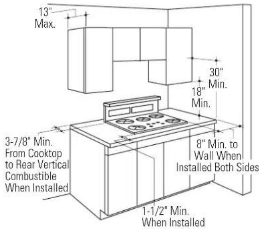
text_image
13" Max. 30" Min. 18" Min. 8" Min. to Wall When Installed Both Sides 3-7/8" Min. From Cooktop to Rear Vertical Combustible When Installed 1-1/2" Min. When Installed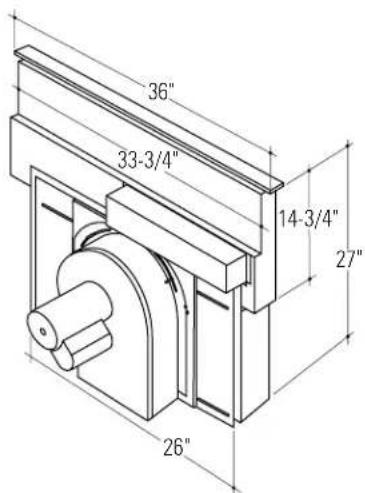
text_image
36" 33-3/4" 14-3/4" 27" 26"Advance Planning
The combined installation of a downdraft vent and cooktop require careful consideration.
Countertop Requirements:
The countertop must have a deep flat surface to accommodate the cooktop and the vent. Countertops with a rolled front edge and backsplash may not provide the flat surface area required.
Base Cabinet Requirements:
This installation requires a 24" min. deep cabinet base. The cabinet must be at least 36" wide.
Clearances
- The downdraft system with blower, motor and ductwork will occupy the cabinet below the cooktop. Drawers cannot be installed below this cooktop.
- Refer to “Dimensions & Clearances” for information on appropriate placement and necessary clearances when planning installation.
- Avoid placing cabinetry directly above the cooktop when possible.
- If cabinetry is used above cooking surface: -Use cabinets no more than 13" deep.
-Maintain 30" minimum clearance between cooktop and unprotected cabinets directly above cooktop.
-If clearance is less than 30", protect cabinet bottoms with flame-retardant millboard at
least 1/4" thick or gypsum board at least 3/16" thick covered with 28 gauge sheet steel or .02" thick copper.
-Clearance between cooktop and protected cabinetry must not be less than 24".
EXCEPTION: Installation of a listed microwave oven or cooking appliance over the cooktop shall conform to the installation instructions packed with that appliance.
-Working areas adjacent to the cooktop should have 18" minimum clearance between countertop and cabinet bottom.
•Installation must conform with local codes.
In the absence of local codes, the gas cooktop must comply with the National Fuel Gas Code, ANSI Z223.1, latest edition.
Ductwork Advance Planning
Prepare ductwork to vent to outdoors:
- Use the shortest and straightest duct run possible:
-Duct run should not exceed equivalent length of 150 feet.
-Refer to "Duct Fittings" chart to calculate equivalent length for various duct configurations.
- The downdraft blower system is designed to use 3-1/4"x10" ductwork. It can be transitioned to 6" round.
- Ductwork MUST be vented to the outside-never into a crawl space, attic or other enclosed space.
- Determine the need for a wall cap or roof cap. Order the cap in advance.
Gas and Electrical Locations
Plan the placement of the electrical outlet and gas carefully. Gas and electrical outlets cannot be placed on the back wall of the cabinet because it may interfere with the downdraft plenum.
- Refer to “Power Supply Locations” page 8 for details.
Cabinetry/Ductwork
Gas Downdraft Cooktop
Tools and Materials Required
•Self-adhesive gasket (supplied)
• Two clamping brackets and screws (supplied)
•Gas pressure regulator (supplied)
• Large flat-blade screwdriver
• Saw
•Carpenter's square
- Pipe wrench
• Manual gas line shut-off valve
•3/4" NPT x 3/4"
I.D. or 1/2" NPT x
1/2" I.D. flare
union adaptor for
connection to
supply line
- Duct work to suit the installation
- 1/2" NPT x 3/4"
I.D. or 1/2" I.D.
flare union adaptor
for connection to
regulator
•Gas-resistant pipe joint sealant
- 5 foot AGA-certified flexible metal appliance connector, 3/4" or 1/2" I.D. to match gas supply line:
-If required by local codes, use solid pipe with fittings.
Note: Purchase new flexible line, DO NOT USE OLD, PREVIOUSLY USED FLEXIBLE LINE.
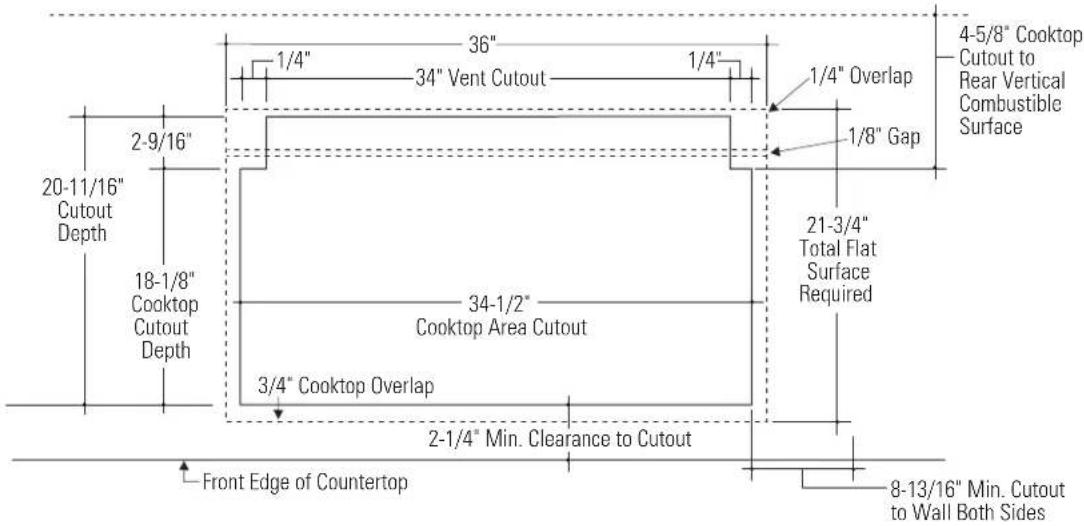
Cut the Opening
Top View-Countertop Surface
text_image
1/4" 36" 1/4" 34" Vent Cutout 2-9/16" 20-11/16" Cutout Depth 18-1/8" Cooktop Cutout Depth 3/4" Cooktop Overlap 2-1/4" Min. Clearance to Cutout Front Edge of Countertop 34-1/2" Cooktop Area Cutout 1/4" Overlap 1/8" Gap 4-5/8" Cooktop Cutout to Rear Vertical Combustible Surface 21-3/4" Total Flat Surface Required 8-13/16" Min. Cutout to Wall Both SidesMeasure carefully when cutting countertop. Make sure sides of opening are parallel and rear and front cuts are exactly perpendicular to sides.
- The Monogram gas downdraft cooktop is designed to fit in a 36" or larger base cabinet.
•The countertop cutout for the cooktop must be:
-34-1/2" at the front of the counter and,
-34" at the back
-18-1/8" front to back notch
-20-11/16" front to back of cutout
The notches at the back of the cutout are:
-2-9/16" forward and 1/4" to the inside.
Follow the illustration shown.
- Allow at least 4-5/8" clearance between back of cutout and combustible wall.
- Allow at least 8-13/16" clearance from right and left sides of cutout to adjacent wall.
- Allow at least 2-1/4" clearance between front of cutout and front edge of countertop.
Caution: Wall coverings,
countertops and cabinets
should withstand 200°F heat
generated by the cooktop.
Venting Options
- The downdraft vent is shipped with the discharge outlet pointing straight down and can be changed to the left or right side.
- The blower outlet is sized for 3-1/2" x 10" and can be transitioned to 6" round.
Side to side adjustments:
The entire blower mounting plate can be adjusted 3-1/2" to the left or right. This will help to align vent discharge to house ductwork.
30^ Rotation
For even more flexibility, the entire blower can be rotated up to 30^ towards the left or 30^ towards right.
Discharge direction
The blower assembly may be removed and turned 90^ for a left or right side discharge.
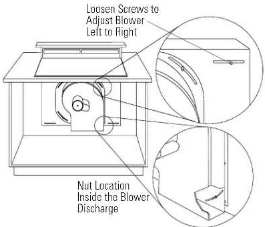
text_image
Loosen Screws to Adjust Blower Left to Right Nut Location Inside the Blower Discharge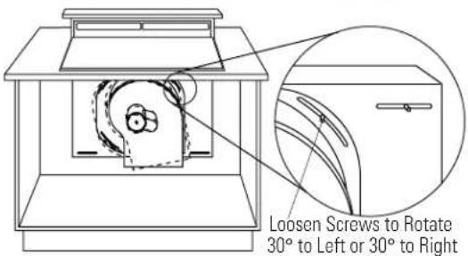
text_image
Loosen Screws to Rotate 30° to Left or 30° to Right30" Rotation Left or Right
- A left or right 90^ direction adjustment should be performed before dropping into the countertop opening.
- Flatten the shipping box to use as a pad.
- Lay the vent on its back onto the pad.
- Remove 4 nuts holding the blower to the mounting plate. See illustration. One nut is just inside the blower discharge.
- Remove and turn the blower to the right or left.
- Reinstall the 4 nuts.
To change to a left or right discharge:
To locate the ductwork holes in the cabinet floor or side walls:
• Temporarily, place vent into the countertop opening.
- Push the vent all the way to the back of the opening.
- If you are transitioning to 6" round, place transition piece over the discharge outlet.
- Mark the location and remove the assembly.
- Cut holes and install ductwork connections.

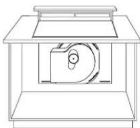
natural_image
Line drawing of a mechanical device with a circular component inside, no text or symbols presentDischarge Down (as Supplied)
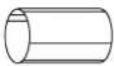
natural_image
Technical line drawing of a mechanical assembly or enclosure with no visible text or symbolsDischarge Left

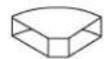
natural_image
Line drawing of a mechanical device with a central circular component and rectangular base (no text or symbols)Discharge Right
Order JXRB57 for installation of the blower and motor below the floor.
Order JXBC57 for installation of the blower and motor outdoors.
Duct Fittings
Use this form to compute maximum permissible lengths for duct runs to outdoors.
Note: Do not exceed maximum permissible equivalent lengths!
Flexible ducting: If flexible metal ducting is used, all the equivalent feet values in the table should be doubled. The flexible metal duct should be straight and smooth and extended as much as possible.
Do NOT use flexible plastic ducting.
Gas Downdraft Cooktop
Model ZGU365 150' maximum equivalent length
Note: Any home ventilation system, such as a cooktop with a downdraft exhaust mechanism, may interrupt the proper flow of combustion air and exhaust required by fireplaces, gas furnaces, gas water heaters and other naturally vented systems. To minimize the chance of interruption of such naturally vented systems, follow the heating equipment manufacturer's guidelines and safety standards such as those published by NFPA and ASHRAE.
| Duct Piece Dimensions Length* Used Length | Total Equivalent Quantity Equivalent | |
 | 6" round, (per foot straight length) | 1 ft. |
 | 3-1/4" x 10" (per foot straight length) | 1 ft. |
 | 6"90° elbow 15 ft. | |
 | 6"45° elbow 9 ft. | |
 | 3-1/4" x 10"90° elbow 16 ft. | |
 | 3-1/4" x 10"45° elbow 5 ft. | |
 | 3-1/4" x 10"90° flat elbow 18 ft. | |
 | 6" roundto 3-1/4" x 10"transition 7 ft. | |
 | 3-1/4" x 10"round to 6"transition 5 ft. | |
 | 6" round to31⁄4" x 10"transition90° elbow 20 ft. | |
 | 3-1/4" x 10" to 6"round transition90° elbow 12 ft. | |
 | 6" roundwall capwith damper 21 ft. | |
 | 3-1/4" x 10"wall capwith damper 27 ft. | |
 | 6" roundroof cap | 20 ft. |
 | 6" roundroof vent | 24 ft. |
Total Duct Run____
Power Supply Locations
Gas supply:
These cooktops are designed to operate on natural gas at 4" of water column pressure or on LP gas at 10" of water column pressure.
- These cooktops are shipped from the factory set for natural gas. If you decide to use this cooktop with LP gas, conversion adjustments must be made by a service technician or other qualified person. JXLP56 conversion kit is required for LP operation.
- The pressure regulator must be connected in series with the manifold of the cooktop and must remain in series with the supply line regardless of type of gas being used.
For proper operation, the maximum inlet pressure to the regulator must be no more than 10" water column pressure for natural gas and 14" water column pressure for LP gas.
- When checking the regulator, the inlet pressure must be at least 1" greater than the regulator output setting.
-If the regulator is set for 4" of water column pressure, the inlet pressure must be at least 5".
-If the regulator is set for 10" of water column pressure, the inlet pressure must be at least 11".
For case of installation, and if local codes permit, the gas supply line into the cooktop should be 1/2" or 3/4" ID flexible metal appliance connector, three to five feet long. Note: Purchase new flexible line. DO NOT USE OLD, PREVIOUSLY USED FLEXIBLE LINE.
- Make gas connection through rear wall, or on cabinet floor at rear, as illustrated.
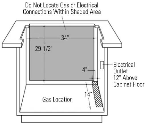
text_image
Do Not Locate Gas or Electrical Connections Within Shaded Area 34" 29-1/2" 4" Gas Location 14" Electrical Outlet 12" Above Cabinet FloorElectrical supply:
- A properly-grounded 3-prong receptacle should be located within reach of cooktop's four foot power cord.
- Locate the receptacle inside the cabinet on the right side wall. See illustration.
IMPORTANT: (Please read carefully). FOR PERSONAL SAFETY, THIS APPLIANCE MUST BE PROPERLY GROUNDED.
The power cord of this appliance is equipped with a three-prong (grounding) plug which mates with a standard three-prong grounding wall receptacle to minimize the possibility of electric shock hazard from this appliance. The customer should have the wall receptacle and circuit checked by a qualified electrician to make sure the receptacle is properly grounded and has correct polarity.
Where a standard two-prong wall receptacle is encountered, it is the personal responsibility and obligation of the customer to have it replaced with a properly grounded three-prong wall receptacle.
Do Not, Under Any Circumstances, Cut Or Remove The Third (ground) Prong From The Power Cord.
Do not use an extension cord.
Installation
Gas Downdraft Cooktop
Remove Packaging
- Remove the shipping materials and the carton, set carton aside. The carton can be used as a pad when changing or adjusting vent direction.
- Remove the plastic ties on both ends at the top of the vent.
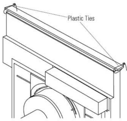
text_image
Plastic TiesStep 1 Install Downdraft Vent
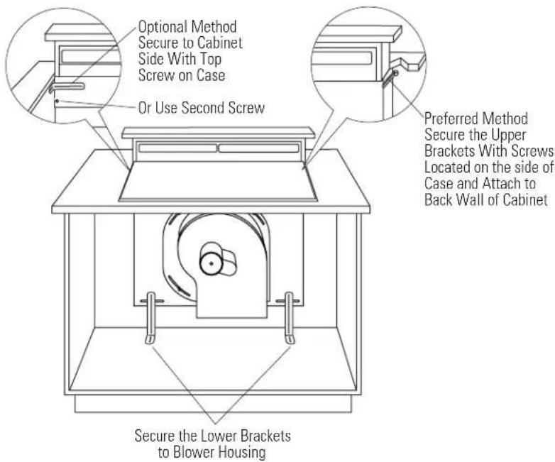
text_image
Optional Method Secure to Cabinet Side With Top Screw on Case Or Use Second Screw Preferred Method Secure the Upper Brackets With Screws Located on the side of Case and Attach to Back Wall of Cabinet Secure the Lower Brackets to Blower HousingPlace the downdraft vent into the countertop cutout, against the back side.
- Secure the downdraft to the countertop supplied brackets. See illustration.
- Fasten brackets to top screws on the front side of the vent, secure to cabinet side wall just below the countertop. Or,
- Fasten one bracket to vent side and secure to cabinet back wall.
- Install two brackets on the bottom of the vent. Attach brackets to slide screws on the vent and to the floor using wood screws (not supplied).
- When installing in a tile countertop surface, it may be necessary to apply a locally approved caulking to cover any gaps.
Step 2 Install the Ductwork
- The downdraft blower system is designed for use with 3-1/4" x 10" ductwork. It can be transitioned to 6" round.
- Ductwork MUST be vented to the outside – never into a crawl space, attic or other enclosed space.
- 6" PVC duct should be used when installing under a concrete slab.
Note: Local building code must be followed for installation and in specifying approved type and schedule of PVC duct used.
- DO NOT USE flexible plastic ducting.
- Always use appropriate roof or wall cap with damper. Laundry type wall caps should never be used.
- Use the straightest duct run possible.
- For satisfactory performance the duct run should not exceed 150 ft. or its equivalent
length when bends or various fittings are used. Refer to the table of equivalent lengths to calculate your installation.
- Install ductwork so the piece of duct nearest the downdraft unit slots INTO the next piece of the duct. Secure the joints with self-tapping screws and apply duct tape around the joints to ensure an airtight seal.
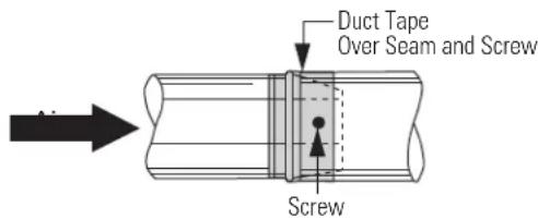
text_image
Duct Tape Over Seam and Screw Screw3 Step Install Pressure Regulator
•Install the supplied pressure regulator and nipple in the gas line as close to the cooktop inlet as possible. Allowances for ventilation ducting may be necessary.
-Make sure the regulator is installed in the right direction.
- Install a manual shut-off valve in the gas line in an easily accessible location.
Note: Instead of using solid piping to connect to pressure regulator, an approved flexible metal appliance connector may be used between the pipe stub and the shut-off valve and the pressure regulator, if local codes permit.
- Appropriate flare nuts and adapters are required at each end of the flexible connector.
- Turn on the gas. Check for leaks using a liquid leak detector at all joints in the system (the pressure test nipple is adjacent to the gas inlet pipe on the rear right hand side of the cooktop bottom.
▲CAUTION Do not use a flame to check for gas leaks.
▲ PRUDENCE IL NE FAUT PAS UTILISER DE FLAMME POUR VÉRIFIER S'IL YA DES FUITES.
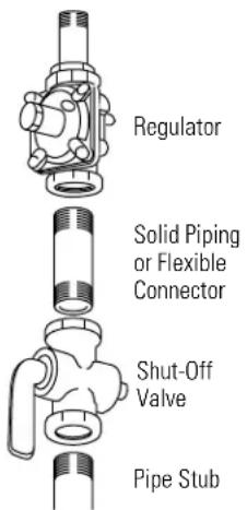
text_image
Regulator Solid Piping or Flexible Connector Shut-Off Valve Pipe StubIMPORTANT: Disconnect the cooktop and the individual shut-off valve from the gas supply piping system during any pressure testing of that system at test pressures greater than 1/2 psig. Isolate the cooktop from the gas supply piping system by closing the individual manual shut-off valve to the cooktop during any pressure testing of the gas supply piping system at test pressures equal to or less than 1/2 psig.
Step 4 Install the Cooktop
Note: If the cooktop is installed into a 36" base cabinet, the pressure regulator MUST BE installed to the bottom of the cooktop before the cooktop is placed into the cabinet.
- Remove packaging from the cooktop.
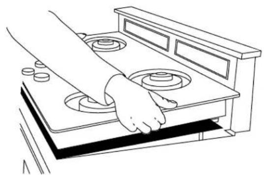
•To insure a good fit, position the cooktop over the cutout opening and carefully lower into place. Check edges all the way around to be sure all cutout edges are concealed and there are no gaps.
•Carefully, lift and remove the cooktop. - Cut a 3/16" gasket strip in half. Peel off the backing and apply to the underside of the glass cooktop edge.
-on each side at least 3/8" from the back and as close to the edge as possible without protruding. - Apply the other gasket strip to the underside of the glass at the front of the cooktop.
- Remove remaining adhesive backing.
- Position the cooktop over the opening, making sure that the power cord is dropped into the cabinet.
- Lower the cooktop into the cutout, pressing gently and evenly to seat.
Note: If the cooktop is installed in a 36" base cabinet, the mounting brackets cannot be used because of interference with the cabinet sides. In this case, the cooktop can be secured to the cabinet with angle brackets (not supplied).
-Remove one screw at the bottom of the cooktop body on both sides and secure the bracket with those screws. Then, secure the brackets to the cabinet sides.
- Insert hold-down bracket into highest slots on the right and left sides of the cooktop: - Cooktop has three slots, the highest available will depend on the thickness of the countertop.
- Secure the brackets to the underside of the countertop with screws provided.
natural_image
Line drawing of a hand operating a portable stove with four circular vent holes (no text or symbols)
text_image
1/16" 3/8"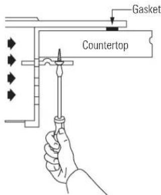
text_image
Gasket Countertop5 Step Electrical Connections
- Connect the 3-pin plastic plug from the blower/motor assembly to the 3-pin plastic socket on the underside of the vent, next to the conduit.
- Slide the metal cover over the connection and secure with screws.

natural_image
Technical line drawing of a mechanical assembly with a lever and base (no text or symbols)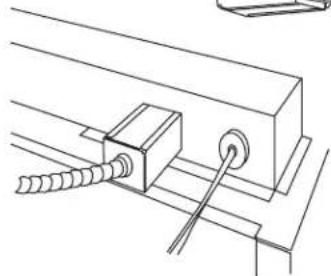
natural_image
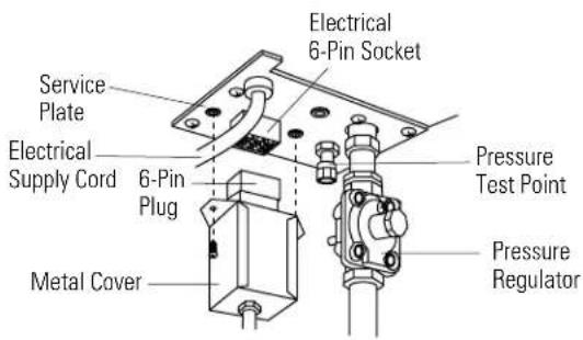
Technical line drawing of a mechanical assembly with threaded rod and circular component (no text or symbols)- Connect the 6-pin plastic plug from the downdraft assembly to the 6-pin plastic socket on the underside of the cooktop, next to the power cord.
- Slide the metal cover over the connection and secure with screws.
text_image
Service Plate Electrical Supply Cord 6-Pin Plug Metal Cover Electrical 6-Pin Socket Pressure Test Point Pressure RegulatorStep 6 Connect Power
- Plug power cords into properly grounded receptacle.
Step 7 Assemble Burners, Check Ignition
- Assemble burner as shown. Check to be sure that burner heads are securely seated and caps are positioned as shown.

text_image
Burner Grate Burner Cap Burner Head Burner Bowl Make sure slot in burner head is positioned over electrode Electrode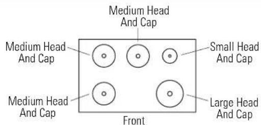
text_image
Medium Head And Cap Medium Head And Cap Small Head And Cap Medium Head And Cap Large Head And Cap Front- Check for proper ignition:
-Push in one control knob and turn 90° to HIGH position.
- The igniter will spark and the burner will light; the igniter will cease sparking when the burner is lit.
-First test may require some time, while air is flushed out of the gas line.
-Turn knob to OFF.
-Repeat the procedure for each burner.

Install
Filters
Check
Operation of
Downdraft
To raise the vent, turn the VENT knob to RAISE/LOWER.
- Hold the knob until the vent begins to raise. - The vent will automatically stop when it is fully extended.
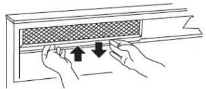
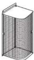
- Tip filter into the opening and pull straight down so that the filter rests on slides.
- Slide the filter to the right side.
- Tip the other filter into the opening and pull straight down.
•To turn the fan on, turn the FAN knob to HIGH.
-Continue turning the FAN knob to select a fan speed between HIGH and LOW.
Note: It is not necessary to turn the fan OFF before lowering the vent. The fan will automatically turn off when the vent is lowered.
When the fan is not turned off before lowering the vent, it will automatically come on at the previously selected speed when the vent is fully raised.
To lower the vent, turn the VENT knob to RAISE/LOWER. Hold the knob until the vent begins to lower.
natural_image
Illustration of hands installing or adjusting a window panel with arrows indicating direction (no text or symbols)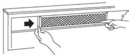
natural_image
Illustration of hands installing a gridded panel on a cabinet (no text or symbols)
natural_image
Illustration of hands adjusting a window with arrows indicating direction (no text or symbols)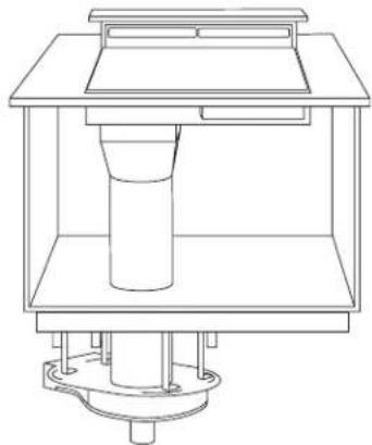
natural_image
Technical line drawing of a mechanical assembly with a cylindrical component mounted on a base (no text or symbols)This kit provides for the installation of the blower and motor outside of the cabinet, such as below the floor. Use this kit for indoor remote installations only.
Note: A 3-1/4" x 10 transition to 6" round is required.
Tools and Materials required:
- Pencil
- Measuring tape
- Drill with appropriate bits
- Nut driver
- Junction box
- Wire nuts
- Safety glasses
- 3-1/4" x 10" to 6" round transition.
- 3-1/4 x 10" duct, (or 6" round) sufficient length to reach the outdoor wall cap or roof cap.
- Electrical cable and connectors, sufficient length to connect the downdraft vent to the remote blower location. 14-guage min. is recommended, must conform to local codes.
Parts Supplied
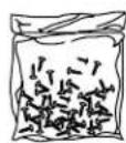
Package of screws

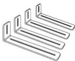
natural_image
Pure diagram of four horizontal metal bars with no text or symbolsHanger Brackets

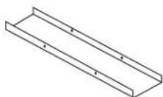
Cover Plate
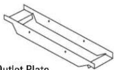
Outlet Plate
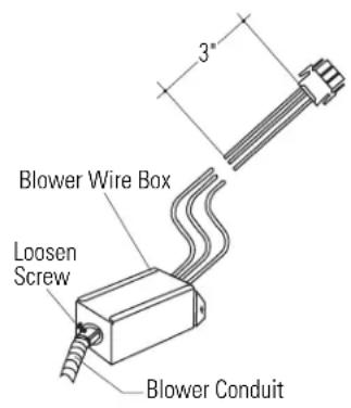
Step 1 Prepare the Vent

text_image
Blower Wire Box Loosen Screw Blower Conduit 3"- Flatten the shipping box to use as a pad.
- Place the unit on its back onto the protective pad.
- Remove the wire box on the plenum.
- Cut the blower leads approximately 3" from the plug on the end of the vent.
- Remove the blower conduit by loosening the screw on the fitting.
- Set aside the 3" wire leads with plug, wire box and screws.
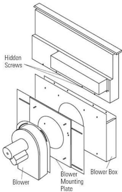
Step 1 (continued)
- Remove the 4 nuts holding the blower to the mounting plate. One nut is hidden inside the outlet. Remove blower.
- Remove the blower mounting plate.
- Remove 2 screws along the bottom of the blower box which are visible once blower plate is removed.
- Carefully, turn the unit over to access the back side.
- Remove 4 screws along the top of the blower box.
- Turn unit over and remove the 4 screws along the top.
- Remove the blower box.
- Retain all screws.
Important: Save any unused parts. If the appliance is relocated at a later time, parts may be needed.

text_image
Hidden Screws Blower Blower Mounting Plate Blower BoxStep 2 Determine Blower Location
• Determine location of the blower and motor.
- The blower will fit between floor joists, 16" on center. Or, provide a surface to attach the entire assembly to the underside of the floor.
- Secure mounting brackets to the top of the blower with screws and nuts. One bracket in each corner, as illustrated.
- Set the bracket at the ends of the curved slots to reach a 14-1/2" span between floor joists, or adjust for your installation situation.
- Mark the installation location and cut hole for 6" round duct.
- Secure the blower to the joists.

text_image
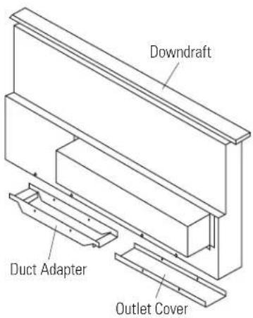
14-1/2"Step 3 Connect Ductwork
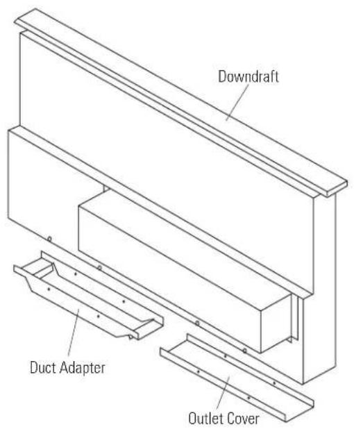
text_image
Downdraft Duct Adapter Outlet Cover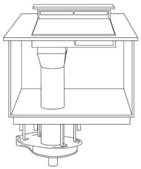
natural_image
Technical line drawing of a mechanical assembly with a cylindrical component and base mount (no text or symbols)- The downdraft plenum can discharge from either the right or left side. Select the side that provides the best alignment to ductwork extending to the blower assembly below.
- For a left side discharge, install the outlet plate to the bottom of the plenum on the left side. Install the cover plate to the bottom of the right side. Reverse plates for a right side discharge.
- Connect the plenum to the ductwork. A transition is required to connect the 3-1/4" x 10" duct to the 6" round inlet on the blower.
- Tape to seal all joints.
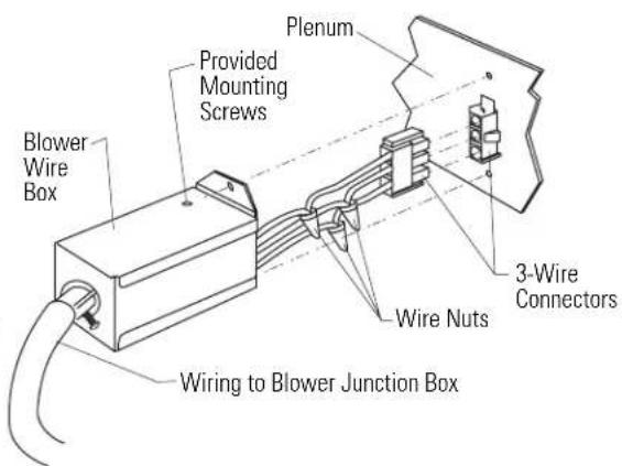
Step 4 Connect Electrical
- Use electrical cable and connectors that conform to local codes (14 gauge min. is recommended). Use a length to reach between the vent and the blower/motor location.
- Attach the wire box removed from the blower conduit to the end of new wiring.
- Use wire nuts to secure the wire to the 3" remaining wires with plug.
- Insert the plug into the mating plug on the vent.
- Reinstall wire box with original screws.
• Install a junction box withing reach of the blower conduit.
- Use a conduit fitting to secure conduit to junction box. The red plastic anti-short bushing should be secured to the end of the conduit.
- Use wire nuts to connect wires.
text_image
Plenum Provided Mounting Screws Blower Wire Box Wire Nuts 3-Wire Connectors Wiring to Blower Junction Box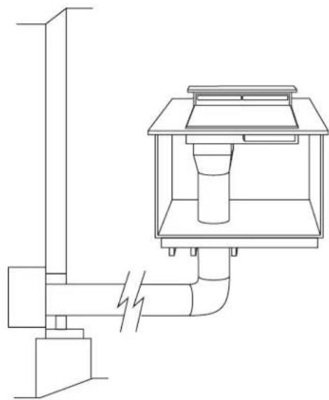
natural_image
Technical line drawing of a mechanical or electrical component with no visible text or symbolsThe blower and motor assembly can be mounted on an outside wall. This kit provides a means to mount the blower outside with a protective cover.
Materials Required
(not supplied)
- Approved liquid tight service connections for use between the wire compartment on the base and inside the structure.
- 7 wire nuts or other approved connectors.
- Six 5/16" dia. fasteners compatible with the type of material the base is being fastened to.
- 3-1/4" x 10" to 6" round transition.
- 3-1/4 x 10" duct, (or 6" round) sufficient length to reach the outdoor installation location.
- Electrical cable and connectors, sufficient length to connect the downdraft vent to the remote blower location. 14-guage min. is recommended, must conform to local codes.
Tools required:
- Pencil or chalk
- Measuring tape
- Drill with appropriate bits
• Phillips head screwdriver - 1/4" Nut driver
- Wire nuts
- Safely glasses
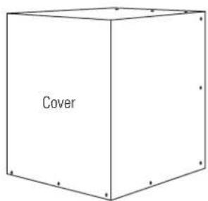
Step 1 Check Parts Supplied
- Separate the cover from the base assembly by removing 5 screws. Retain screws.
- Check to be sure all parts are present.
text_image
Cover
Junction Box

text_image
Cover Base Assembly Outlet Pan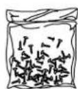
Package of screws
Cover Plate
natural_image
Pure diagram of four identical L-shaped metal brackets without any text or symbols4 Hanger Brackets
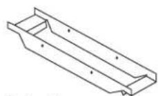
Outlet Plate
Damper
Step 2 Mark Mounting Location
- The base is designed to be mounted to studs on 16" centers. Use the dimensions shown to determine the location of the ducting and wiring through the wall.
- Or Place the base against the exterior wall and mark the 6 mounting locations, the 6" duct location and the hole for the wiring. Use pencil or chalk.
- The bottom of the base assembly must be 10" min. above the ground. There should be no obstructions to the discharge from the damper.
- Cut a 6-1/8" dia. hole in the vertical structure to accommodate a 6" round duct another hole for the wiring.
- Drill 6 pilot holes through the wall for the 6/16" fasteners.
CAUTION: When cutting or drilling into a wall or ceiling, do not damage electrical wiring or hidden utilities. Check for interference with floor joists and stud walls. If necessary, locate the base to provide a secure installation.
- Place a 6" round duct through the hole extending approximately 3" from the wall to provide a proper seal with the blower. Secure the duct to the building structure to prevent it from being pushed back when the blower is installed.

text_image
Align With Duct Opening On Outside Wall 12-15/16" 1-13/16" 6-11/16" 16" 6 Holes For 5/16 Fastners 4-3/4" 6" 12" 10" Min Above GroundStep 3 Prepare the Vent
- Flatten the shipping box to use as a pad.
- Place the unit on its back onto the protective pad.
- Remove the wire box on the plenum.
- Cut the blower leads approximately 3" from the plug on the end of the vent.
- Remove the blower conduit by loosening the screw on the fitting.
- Set aside the 3" wire leads with plug, wire box and screws.
text_image
Blower Wire Box Loosen Screw Blower ConduitStep 3 (continued)
- Remove the 4 nuts holding the blower to the mounting plate. One nut is hidden inside the outlet. Remove blower.
- Remove the blower mounting plate.
- Remove 2 screws along the bottom of the blower box which are visible once blower plate is removed.
- Carefully, turn the unit over to access the back side.
- Remove 4 screws along the top of the blower box.
- Turn the unit over and remove the 4 screws along the top.
- Remove the blower box.
- Retain all screws.
Important: Save any unused parts. If the appliance is relocated at a later time, parts may be needed.
text_image
Hidden Screws Blower Blower Mounting Plate Blower Box- The downdraft plenum can discharge from either the right or left side. Select the side that provides the best alignment to ductwork extending to the blower assembly.
- For a left side discharge, install the outlet plate to the bottom of the plenum on the left side. Install the cover plate to the bottom of the right side. Reverse plates for a right side discharge.
text_image
Downdraft Duct Adapter Outlet Cover- A transition is required to connect the 3-1/4" x 10" duct to the 6" round inlet on the blower.
- Tape to seal all joints.
Step 4 Connect Blower Wires
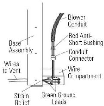
- Check that the red plastic anti-short bushing is secured in the end of the conduit. Install the blower conduit into the conduit connector on the junction box and tighten the screw.
• Install a liquid tight fitting in the hole of the wire compartment on the base, sized to fit wire being used. - Run the electrical wiring from the downdraft vent to the wire compartment.
- Attach the green ground leads from the wire compartment, connecting one to the green ground lead on the blower and the other to the ground lead of the wiring from the downdraft vent.
- Connect the neutral (white) and power lead (black) from the blower to the leads from the downdraft vent.
- Use wire nuts to connect wires.
text_image
Base Assembly Wires to Vent Strain Relief Blower Conduit Red Anti-Short Bushing Conduit Connector Wire Compartment Green Ground Leads5 Step Connect Electrical
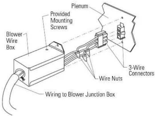
- Use electrical cable and connectors that conform to local codes (14 gauge min. is recommended). Use a length to reach between the vent and the blower/motor location.
- Attach the wire box removed from the blower conduit to the end of new wiaring.
- Use wire nuts to secure the wire to the 3" remaining wires with plug.
- Insert the plug into the mating plug on the vent.
- Reinstall wire box with original screws.
text_image
Plenum Provided Mounting Screws Blower Wire Box Wire Nuts 3-Wire Connectors Wiring to Blower Junction BoxStep 6 Mount Blower
- Mount the blower onto the mounting plate. Secure with original nuts.
• Install damper to bottom of outlet with 4 screws.
natural_image
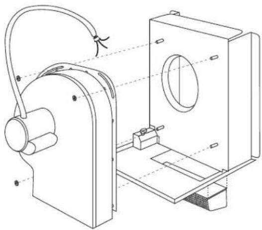
Technical line drawing of a mechanical assembly with no visible text or symbolsStep 7 Finalize Installation
- Place the cover over the the assembled kit and secure with 16 screws.

natural_image
Technical line drawing of a mechanical assembly with a downward arrow indicating motion (no text or symbols present)NOTE: While performing installations described in this book, safety glasses or goggles should be worn.
To obtain specific information concerning any Monogram product or service, call GE Answer Center® consumer information service at 800.626.2000—any time, day or night.
For Monogram local service in your area, call 1-800-444-1845.
NOTE: Product improvement is a continuing endeavor at General Electric. Therefore, materials, appearance and specifications are subject to change without notice.
Pub. No. 19-8999-1
Part No. 183D5580P082
12000 GE Appliances
(N.D. 505) 5/00
Printed in Mexico