ZISB36DC - Cooker GE - Free user manual and instructions
Find the device manual for free ZISB36DC GE in PDF.

User questions about ZISB36DC GE
0 question about this device. Answer the ones you know or ask your own.
Ask a new question about this device
Download the instructions for your Cooker in PDF format for free! Find your manual ZISB36DC - GE and take your electronic device back in hand. On this page are published all the documents necessary for the use of your device. ZISB36DC by GE.
USER MANUAL ZISB36DC GE
36" Built-In Refrigerators
Custom
Options Guide
and
Installation
Instructions
With Custom Panel Dimensions and Trim Kit
Installation Instructions
These Monogram built-in refrigerators are designed to be customized with decorator door and grille panels. Field installed panels are required.
Factory installed trim will accommodate 1/4" thick custom panels or optional Lexan® and Stainless Steel panel kits.
Optional trim kits allow an even broader range of custom appearance options.
Read this booklet carefully to accomplish the desired appearance and to insure a trouble free installation.
This booklet contains information and illustrations to demonstrate custom possibilities. Custom door and grille panel sizes vary to accommodate the kit being used. Dimensions for each application are included and can be faxed or sent to the cabinet manufacturer so that the panels can be constructed accurately.
Models:
ZIS36N
ZISW36D
ZISB36D
Before you begin - Read these instructions completely and carefully.
IMPORTANT - Save these instructions for local inspector's use.
IMPORTANT - OBSERVE ALL GOVERNING CODES AND ORDINANCES.
Note to Installer - Be sure to leave these instructions with the Consumer.
Note to Consumer - Keep these instructions with your Use and Care Book for future reference.

WARNING
This appliance must be properly grounded. See "Grounding the Refrigerator," page 15.

ATTENTION
If you have a question concerning the installation of this product, call the GE Answer Center® Consumer Information Service at 800.626.2000, 24 hours a day, 7 days a week.
If you received a damaged refrigerator, you should immediately contact your dealer or builder.
Proper installation is the responsibility of the installer. Product failure due to improper installation is not covered under the GE Appliance Warranty. See the Use & Care Guide for warranty information.
For Monogram local service in your area, 1-800-444-1845.
For Monogram service in Canada, 1-888-880-3030.
For Monogram Parts and Accessories, call 1-800-626-2002.

WARNING
- Use this appliance only for its intended purpose.
- Immediately repair or replace electric service cords that have become frayed or damaged.
- Unplug the refrigerator before cleaning or making repairs.
- Repairs should be made by a qualified service technician.

ATTENTION
Advance Planning for a Flush Installation 3
Cutout and Product Dimensions 3
Installation Between Base & Wall Cabinets 4
Installation At End-of-Run 4
Frameless Cabinets 4
Accessory Panel Kits 4
Advance Planning, Exterior Appearance Options 5
Appearance Examples, Trim Kit Descriptions 5
Custom Panel Dimensions
ZIS36N 6-9
ZISW36D, ZISB36D 10-13
Side Panel or Filler Options 14
Installation Instructions 15-20
Trim Kits
ZKH1 Trim Kit Installation Instructions Custom Handles with 1/4" Thick Panels 21-25
ZG2 Trim Kit Installation Instructions Grille Panel Frame Adjustment 26
ZKT36 Trim Kit Installation Instructions 3/4" Thick Custom Panels ....27-32
ZKHT1 Trim kit Installation Instructions Custom Handles with 3/4" Thick Panels ....33-37
ZKHSS1 Trim Kit Installation Instructions Tubular Stainless Steel Handles for 1/4" Panel Installation ....38-41
ZKHTSS1 Trim Kit Installation Instructions Tubular Stainless Steel Handles for 3/4" Panel Installation ....42-45
ZWCD1 Trim Kit Installation Instructions Custom Dispenser Collar 46-47
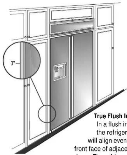
Flush or Semi-Flush Enclosure Installations
text_image
0" True Flush In In a flush in the refrigerator will align even front face of adjace doors. The refrigeratorTrue Flush Installation In a flush installation, the refrigerator doors will align evenly with the front face of adjacent cabinet doors. The refrigerator blends into the surrounding cabinetry.
Monogram built-in refrigerators can be installed flush with typical 24-3/4" deep cabinetry.
When installed semi-flush, the case trim will conceal slight gaps around the enclosure. The refrigerator will project forward approximately 3/4" beyond the front face of surrounding cabinetry.
In any installation situation, a wide range of appearance options can be accomplished through the use of one or more trim kits. See trim kit descriptions and appearance options on page 5.
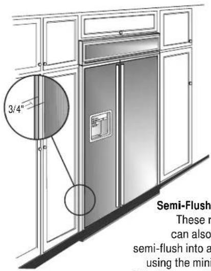
text_image
3/4" Semi-Flush These r can also semi-flush into a using the miniSemi-Flush Installation These refrigerators can also be installed semi-flush into an enclosure using the minimum cutout width. The case trim creates a frame around the opening.
Side Panel Requirements:
- Side panels are not required whenever the refrigerator is installed into an enclosure or between pantry and oven cabinets.
- Side panels are required whenever the sides of the refrigerator are exposed.
- Side panel sizes vary depending on the type of installation being made.
To accomplish an attractive installation, you must:
- Determine the need for side panels.
- Determine side panel thickness.
- Order matching side panels from the cabinet manufacturer. Be sure to provide the exact dimensions.
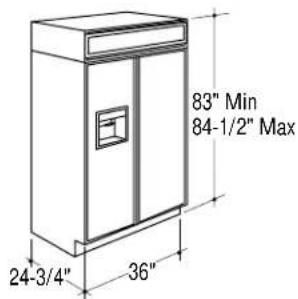
Enclosure Cutout and Product Dimensions
- To achieve a flush fit the finished cutout width must be at least 36" wide.
- A semi-flush installation requires 35-1/2" min. finished cutout width.
- The electrical and water locations must be located as shown for either type of installation.
text_image
83" Min 84-1/2" Max 24-3/4" 36"
text_image
84 1/2" max 83-1/4" min Finished Opening *Finished Width Electrical Area 7" 5" 24 3/4" Total Depth 12 3/8" Water Supply 5" 3 1/2" Wall View 74" From Floor to Bottom of Electrical 3 1/2"*36" Min. for a flush installation 35-1/2" Min. for a semi-flush installation Note: Additional cutout width may be required when side panels are used. Add side panel thickness to the finished cutout to calculate rough-in width. See installation examples on the following page.
Design Information
36" Built-In Refrigerators
Installation Examples
Side panels are required whenever the sides of the refrigerator will be exposed.
1/2" to 3/4" side panels are normally set into place and fastened to adjacent cabinetry or to the back wall before rolling the refrigerator into the opening.
Therefore, the rough-in dimensions must allow for side panel thickness. In both a flush and semi-flush installation, the finished dimension, (the width of the opening after side panels are installed), must accommodate the full width of the refrigerator.
See page 14 for side panel sizes.
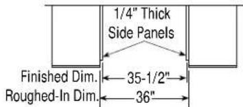
Installation Between Base & Wall Cabinets
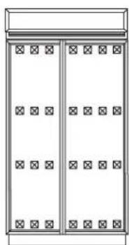
natural_image
Simple line drawing of a cabinet with doors and a central door (no text or symbols)Note: 1/4" thick side panels can be inserted into the case trim, making the rough-in the same as the outside trim width, 36".
Flush and Semi-Flush Installations
text_image
1/4" Thick Side Panels Finished Dim. 35-1/2" Roughed-In Dim. 36"
text_image
Refrigerator Cabinet Refrigerator door Cabinet1/4" Side Panels. Insert end of side panel into trim
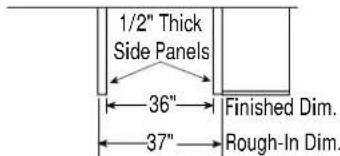
Installation At End-of-Run

natural_image
Architectural diagram of a double door with doors and a cabinet (no text or symbols)Note: 1/2" thick side panels shown. Side panels can be any thickness. Add side panel thickness to outside trim width (36") to calculate the rough-in dimension. The leading (front) edge must be finished to match surrounding cabinetry.
Flush and Semi-Flush Installations
text_image
1/2" Thick Side Panels 36" 37" Finished Dim. Rough-In Dim.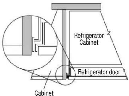
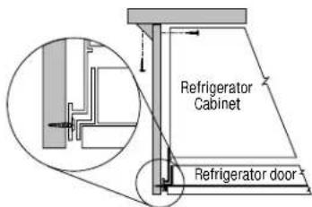
text_image
Refrigerator Cabinet Refrigerator door Cabinet1/2" To 3/4" Side Panels. Leading Edge Flush With Cabinet
Frameless Cabinets
Side panels, 1/2" minimum thickness are required when using frameless cabinets. The side panel acts as a spacer between the cabinet and the case trim and prevents interference with cabinet door swing. The leading (front) edge must be finished to match surrounding cabinetry.
1/2" To 3/4" Side Panels. Leading Edge Flush With Cabinet
text_image
Refrigerator Cabinet Refrigerator doorAccessory Panel Kits
Field installed door and grille panels are required. The factory installed trim will accept accessory panel kits. White or black Lexan® and stainless steel kits are available. Panels are cut to size and ready to install. These panel kits must be ordered separately.
A wide range of custom appearance options can be created with optional custom trim kits. See the opposite page for examples and trim kit descriptions.
| Model Black White Stainless | |
| ZIS36N ZWBP36 ZWWP36 ZWSP36 | |
| ZISW36D ZWWP36D ZWS P36D | |
| ZISB36D ZWBP36D ZWSP36D |
Advance planning exterior appearance options
These refrigerators are designed to be customized with decorator door and grille panels. Field installed custom door and grille panels are required.
Factory installed trim accommodates 1/4" thick custom panels, Lexan® or stainless steel panel kits.
Appearance options are accomplished through the use of one or more trim kits. Kits must be ordered separately.
Door and grille panel sizes vary to accommodate the kit being used. Sizes are provided in this booklet.
Important: Maximum weight for fresh food panels is 50 pounds and 30 pounds for freezer door panels.
You should:
- Select the appearance option.
- Order the trim kit(s) for that option.
- Order the custom door and grille panels from the cabinet manufacturer. The exact dimension for each trim kit application is provided in this booklet. Find and pull out the page for your application and fax or send it to the cabinet manufacturer. The cabinet manufacturer must have this information to construct the panels accurately.
- Determine the final installation situation and order matching side panels.
3/4" thick custom panels—Without trim kits
A raised panel design, screwed or glued to a 1/4" thick backing can be used. See pages 7 and 11 for panel sizes and clearances.
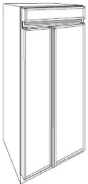
Appearance Examples Trim kit Descriptions
natural_image
Line drawing of a two-door refrigerator with top shelf (no text or symbols)1/4" and 3/4" panels with standard handles. No trim kits required.
natural_image
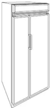
Line drawing of a two-door refrigerator with a handle (no text or symbols)1/4 Custom panels with custom handles. Trim Kit ZKH1.
natural_image
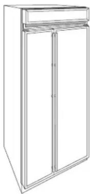
Line drawing of a two-door refrigerator with top shelf (no text or symbols)1/4 Custom panels with Tubular Stainless Steel handles. Trim Kit ZKHSS1.
natural_image
Line drawing of a simple refrigerator with front panel and side door (no text or symbols)3/4" Custom panels with custom handles. Trim kits ZKT36 & ZKHT1.

natural_image
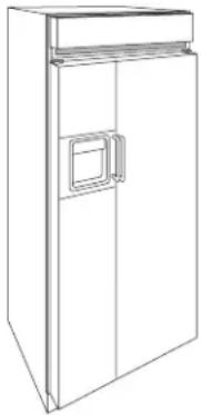
Line drawing of a double-door refrigerator with a front panel and door (no text or symbols)3/4" Custom panels with Tubular Stainless Steel handles and custom dispenser collar. Trim Kits ZKHTSS1, ZKT36 & ZWCD1.
Door Handle Options
ZKH1 – Provides the necessary framework to install custom handles, of your choice, onto 1/4" thick panels. (Handles not included.)
ZKHSS1 – Tubular stainless steel handles for 1/4" thick panel installations.
ZKHT1 – Provides the necessary framework to install custom handles, of your choice, onto 3/4" thick panels. (Handles not included.) This kit must be used in combination with ZKT36.
ZKHTSS1 – Tubular stainless steel handles for 3/4" thick panel installations. This kit must be used in combination with ZKT36.
Custom Panel Options
ZKT36 – Provides for the installation of 3/4" thick trimless custom door and grille panels with the standard (supplied) full length handle.
Dispenser Options
ZWCD1 – Provides for the installation of a custom collar trim on the dispenser and for one continuous custom panel on the freezer door. This kit can be used alone, or with all other kits.
Toekick Option
ZWT1 – White toekick (supplied toekick is black). Includes a white toekick to fit 36, 42, 48" side-by-side models and 36" bottom mount and single door models.
Grille Panel Options
ZG2 – Provides 1/4" grille panel frame side pieces for 83", 83-1/2" and 84-1/2" installation heights. The supplied grille panel frame is factory set for 84".
Note: ZG1 Grille Panel Kit is available for models produced before January 1997. Panel sizes for ZG1 and ZG2 are the same. The ZG1 kit can be ordered from your Monogram dealer.

text_image
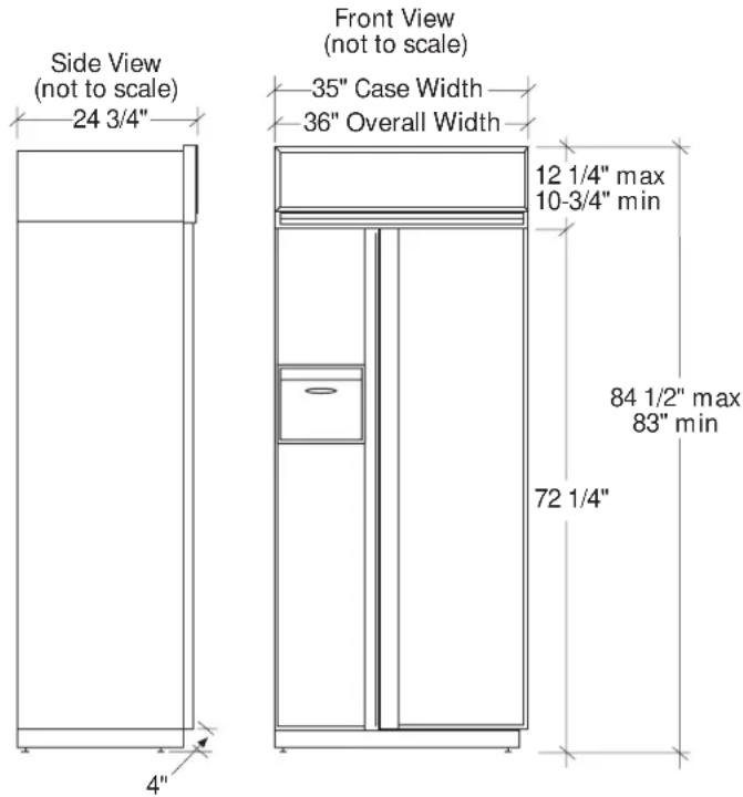
Side View (not to scale) 24 3/4" Front View (not to scale) 35" Case Width 36" Overall Width 12 1/4" max 10-3/4" min 84 1/2" max 83" min 72 1/4" 4"
text_image
Finished Width Wall View (not to Scale) Locate Grounded Electrical outlet Within Solid Area Above 7" 5" -12 3/8" Locate Water Supply Within the Shaded Area Below 74" From Floor to Bottom of Electrical Area 84 1/2" max 83-1/4" min Finished Opening 5" 3 1/2" 3 1/2"*36" Min. for a flush installation into an enclosure.
*35-1/2" Min. for a semi-flush installation into an enclosure.
Note: Additional cutout width may be required when side panels are used. Add side panel thickness to the finished cutout to calculate rough-in width. See installation examples on page 4.
ZIS36N
(Non-dispenser)
Design Information
Cutout dimensions, clearances and side panel sizes are determined by the many installation options available. Side panels must be used whenever the sides of the refrigerator will be exposed. Side panels are not required when refrigerator is installed into an enclosure or between pantry and oven cabinets. IMPORTANT-Side panels, 1/2" minimum thickness, are required when using FRAMELESS CABINETS.
- Field installed custom panels, Lexan ^1 or stainless steel panels are required. The door panels and grille panel sizes vary to accommodate the kit being used.
- A custom toekick can be installed to match or complement the surrounding cabinetry. Use the supplied toekick as a template to cut out notches around hinges and water lines.
Optional Kits:
- ZWBP36: Black Lexan ☐ Panel Kit (no trim kit required).
- ZWWP36: White Lexan ^1 Panel Kit (no trim kit required).
- ZWSP36: Stainless Steel Panel Kit (no trim kit required).
- ZKH1: For installation of a custom handle on 1/4" panels.
- ZKT36: For installation of 3/4" custom panels.
- ZKHT1: For installation of a custom handle on 3/4" panels. (This kit must be used in combination with ZKT36.)
- ZKHSS1: Tubular Stainless Steel handles on 1/4" panels.
- ZKHTSS1: Tubular Stainless Steel handles on 3/4" panels. (This kit must be used in combination with ZKT36.)
- ZG2: 1/4" grille panel frame side pieces for 83", 83-1/2" and 84-1/2" installation heights. Factory set height is 84".
- ZWT1: White toekick (supplied toekick is black). Includes a white toekick to fit 36, 42, 48" side-by-side models and 36" bottom mount and single door models.
Additional Specifications
- A 115 volt 60 Hz., 15 or 20 amp power supply is required. An individual properly grounded branch circuit or circuit breaker is recommended. Install a properly grounded 3-prong electrical receptacle recessed into the back wall. Electrical must be located on rear wall.
- Water line can enter opening through the floor or back wall. The water line should be 1/4" O.D. copper tubing between the cold water line and water connection location, long enough to extend to the front of the refrigerator. Installation of an easily accessible shut off valve in the water line is recommended.
Clearances
If the refrigerator is to be installed in a corner:
- A 4" min. clearance between the case trim and adjacent wall on both sides of the refrigerator will assure a 90° door opening and access to all drawers. A 10" clearance is required on both sides for removal of pans.
Custom Door Panel Dimensions Using Standard Trim
1/4" thick panels
or
Panels secured to 1/4" thick backing

text_image
Freezer Panel Fresh Food Panel 67 7/8" 15 1/4" 19 1/4"Important: Maximum weight for fresh food panels is 50 pounds and 30 pounds for freezer door panels.
text_image
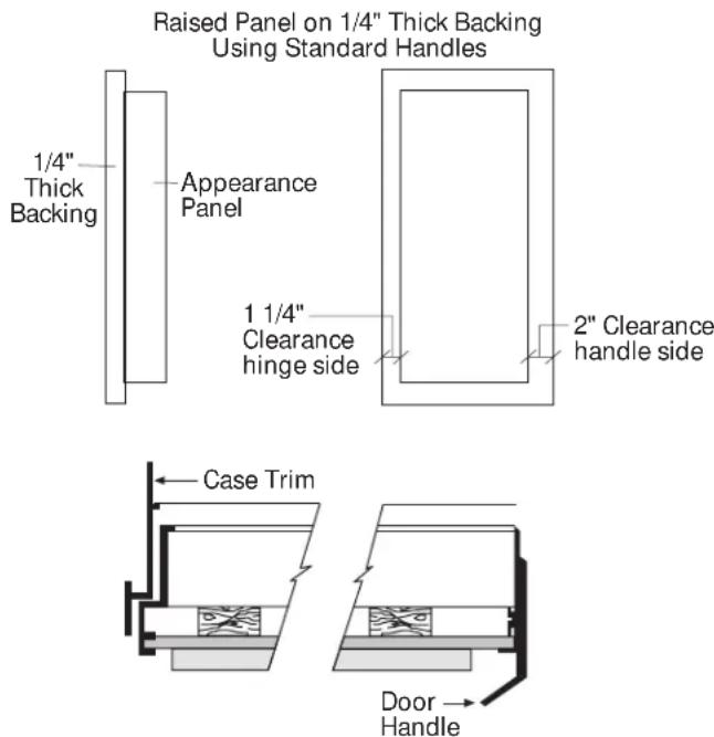
Raised Panel on 1/4" Thick Backing Using Standard Handles 1/4" Thick Backing Appearance Panel 1 1/4" Clearance hinge side 2" Clearance handle side Case Trim Door HandleZIS36N (non-dispenser)
Standard Trim with 1/4" Panels
- 1/4" Panels: Cut panels to size.
- Custom handles with 1/4" door panels require Trim Kit ZKH1 (or ZKHSS1 for tubular-stainless steel handles).
Standard Trim with Panels secured to 1/4" thick backing
- Applying a raised panel design to a 1/4" thick backing (screwed or glued): Cut 1/4" panels to size, fabricate the raised panel to permit clearances of at least 2" from the handle side for fingertip clearance of the standard handle, 1-1/4" from the hinge side to avoid striking adjacent cabinetry and 5/16" from the top and bottom edges to allow for the trim flange then install.
- Countertops adjacent to refrigerator installation should be mitered 45^ degrees.
Note: ZKHT1 custom handle kit cannot be used in this configuration.
text_image
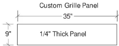
Custom Grille Panel 35" 9" 1/4" Thick PanelThe grille panel frame is factory assembled for 84" installation height. If installation height varies, order ZG2 trim kit which provides optional side trim pieces. Cut grille panel to sizes shown below.
| Installation Height Panel Height | |
| 83" 8" | |
| 83-1/2" 8-1/2" | |
| 84-1/2" 9-1/2" | |
Important: Maintain 1-1/2" min. gap between top of doors and bottom of panel frame.

text_image
Case Trim Door HandleCustom Door Panel Dimensions
Using Trim Kit ZKT36
3/4" thick panel with standard handle
ZIS36N (non-dispenser)
- The ZKT36 trim kit provides for the installation of 3/4" custom door and grille panels, using the standard full-length handle. Cut panels to size and install.
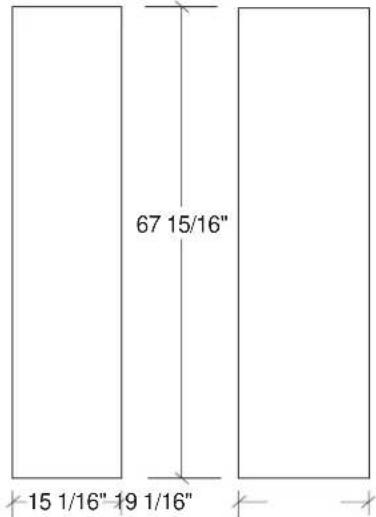
Freezer Panel Fresh Food Panel
text_image
67 15/16" 15 1/16" 19 1/16"Important: Maximum weight for fresh food panels is 50 pounds and 30 pounds for freezer door panels.

text_image
Custom Grille Panel 35 1/2" Over 1/4" Thick (3/4" max) Panel AGrille Panel height can vary to fill installation height.
| Installation Height Dimension A | |
| 83" 8-1/4" | |
| 83-1/2" 8-3/4" | |
| 84" 9-1/4" | |
| 84-1/2" 9-3/4" | |
Important: Maintain 1-1/2" min. gap between top of doors and bottom of grille panel.
Custom Door Panel Dimensions
Using Trim Kits ZKT36
3/4" thick panel
with custom handle
text_image
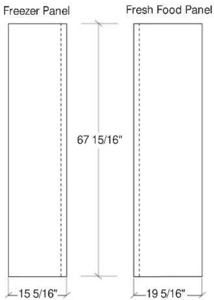
Freezer Panel 67 15/16" 15 5/16" 19 5/16" Fresh Food PanelZIS36N (non-dispenser)
- ZKT36 and ZKHT1 installed together provides for the installation of 3/4" custom door and grille panels, using a custom handle, of your choice. Order ZKHTSS1 for tubular stainless-steel handles. Cut panels to size, rout the handle side of the panels as shown below and install.
Important: Maximum weight for fresh food panels is 50 pounds and 30 pounds for freezer door panels.

text_image
Rout panels to specification below on the handle side of each panel 1 13/16" 1 13/16" 1/4" Freezer Door Face Freezer Door Face Fresh Food Door Face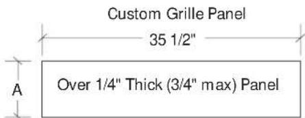
text_image
Custom Grille Panel 35 1/2" Over 1/4" Thick (3/4" max) Panel AGrille Panel height can vary to fill installation height.
| Installation Height Dimension A | |
| 83" 8-1/4" | |
| 83-1/2" 8-3/4" | |
| 84" 9-1/4" | |
| 84-1/2" 9-3/4" | |
Important: Maintain 1-1/2" min. gap between top of doors and bottom of grille panel.
text_image
Side View (not to scale) 24 3/4" Front View (not to scale) 35" Case Width 36" Overall Width 12 1/4" max 10-3/4" min 84 1/2" max 83" min 72 1/4" 4"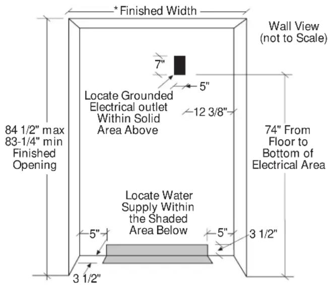
text_image
Finished Width 7" 5" Locate Grounded Electrical outlet Within Solid Area Above 12 3/8" Locate Water Supply Within the Shaded Area Below 5" 3 1/2" 84 1/2" max 83-1/4" min Finished Opening Wall View (not to Scale) 74" From Floor to Bottom of Electrical Area 3 1/2"*36" Min. for a flush installation into an enclosure.
* 35-1/2" Min. for a semi-flush installation into an enclosure.
Note: Additional cutout width may be required when side panels are used. Add side panel thickness to the finished cutout to calculate rough-in width. See installation examples on page 4.
ZISW36D (white dispenser) ZISB36D (black dispenser)
Design Information
Cutout dimensions, clearances and side panel sizes are determined by the many installation options available. Side panels must be used whenever the sides of the refrigerator will be exposed. Side panels are not required when refrigerator is installed into an enclosure or between pantry and oven cabinets. IMPORTANT-Side panels, 1/2" min. thick, are required for FRAMELESS CABINETS.
- Field installed custom panels, Lexan ^1 or stainless steel panels are required. Custom door panels and grille panel sizes vary to accommodate the kit being used.
- A custom toekick can be installed to match or complement the surrounding cabinetry. Use supplied toekick as a template to cut notches for hinges and water lines.
Optional Kits:
- ZWBP36D: Black Lexan ^® Panel Kit (no trim kit required).
- ZWWP36D: White Lexan ^1 Panel Kit (no trim kit required).
- ZWSP36D: Stainless Steel Panel Kit (no trim kit required).
- ZKH1: For installation of custom handles on 1/4" panels.
- ZKT36: For installation of 3/4" custom panels.
- ZKHT1: For installation of custom handles on 3/4" panels. (This kit must be used in combination with ZKT36.)
- ZWCD1: For installation of a custom collar trim on the dispenser for one continuous custom panel on the freezer door.
- ZKHSS1: Tubular Stainless Steel handles on 1/4" panels.
- ZKHTSS1: Tubular Stainless Steel handles on 3/4" panels. (This kit must be used in combination with ZKT36.)
- ZG2: 1/4" grille panel frame side pieces for 83", 83-1/2" and 84-1/2" installation heights. Factory set height is 84".
- ZWT1: White toekick (supplied toekick is black). Includes a white toekick to fit 36, 42, 48" side-by-side models and 36" bottom mount and single door models.
Additional Specifications
- A 115 volt 60 Hz., 15 or 20 amp power supply is required. An individual properly grounded branch circuit or circuit breaker is recommended. Install a properly grounded 3-prong electrical receptacle recessed into the back wall. Electrical must be located on rear wall.
- Water line can enter opening through the floor or back wall. The water line should be 1/4" O.D. copper tubing between the cold water line and water connection location, long enough to extend to the front of the refrigerator. Installation of an easily accessible shut off valve in the water line is recommended.
Clearances
If the refrigerator is to be installed in a corner:
- A 4" min. clearance between the case trim and adjacent wall on both sides of the refrigerator will assure a 90° door opening and access to all drawers. A 10" clearance is required on both sides for removal of pans.
Custom Door Panel Dimensions Using Standard Trim 1/4" thick panels
Panels secured to 1/4" thick backing

text_image
Freezer Panel Standard Dispenser 16 5/8" 36 7/8" 15 1/4" Freezer Panel Custom Dispenser 17 11/16" 67 7/8" 2 9/16" 15 1/4" Fresh Food Panel 19 1/4"Important: Maximum weight for fresh food panels is 50 pounds and 30 pounds for freezer door panels.

text_image
Raised Panel on 1/4" Thick Backing Using Standard Handles 1/4" Thick Backing Appearance Panel 1 1/4" Clearance hinge side 2" Clearance handle side Case Trim Door HandleZISW36D (white dispenser) ZISB36D (black dispenser)
Standard Trim with 1/4" Panels
- 1/4" Panels: Cut panels to size.
- Custom handles with 1/4" door panels require Trim Kit ZKH1. When using ZKH1 with the standard dispenser trim, the length of the custom handle, top to bottom cannot exceed 11-3/4".
• Tubular stainless steel handle kit, ZKHSS1. - Custom collar dispenser trim with 1/4" door panels require trim kit ZWCD1.
Standard Trim with Panels secured to 1/4" thick backing
- Applying a raised panel design to a 1/4" thick backing (screwed or glued): Cut 1/4" panels to size, fabricate the raised panel to permit clearances of at least 2" from the handle side for fingertip clearance of the standard handle, 1-1/4" from the hinge side to avoid striking adjacent cabinetry and 5/16" from the top and bottom edges to allow for the trim flange, then install.
- Countertops adjacent to refrigerator installation should be mitered 45° degrees.
Note: ZWCD1 custom collar dispenser trim and ZKHT1 custom handle kits cannot be used in this configuration.

text_image
Custom Grille Panel 35" 9" 1/4" Thick PanelThe grille panel frame is factory assembled for 84" installation height. If installation height varies, order ZG2 trim kit for optional side trim pieces. Cut grille panel to sizes shown below.
| Installation Height Panel Height | |
| 83" 8" | |
| 83-1/2" 8-1/2" | |
| 84-1/2" 9-1/2" | |
Important: Maintain 1-1/2" min. gap between top of doors and bottom of panel frame.
Custom Dispenser Cutout

text_image
9 7/16" 12 5/16"The Cutout is 9 7/16" wide by 12 5/16" high.
Custom Door Panel Dimensions
Using Trim Kit ZKT36
3/4" thick panel with standard handle and/or ZWCD1 custom collar trim

text_image
Freezer Panel Standard Dispenser 16 11/16" 37" 15 1/16"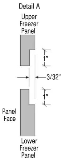
text_image
Detail A Upper Freezer Panel 3/32" Panel Face Lower Freezer Panel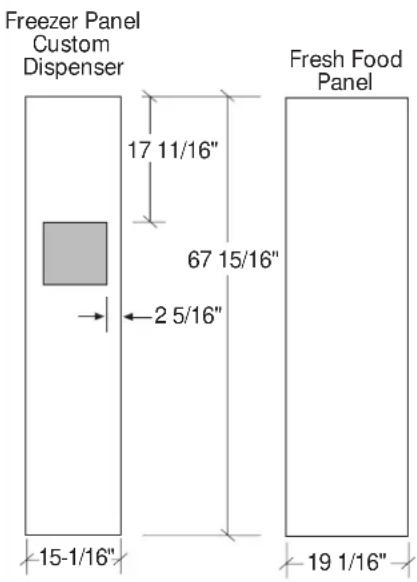
text_image
Freezer Panel Custom Dispenser 17 11/16" 67 15/16" 2 5/16" 15-1/16" 19 1/16" Fresh Food PanelImportant: Maximum weight for fresh food panels is 50 pounds and 30 pounds for freezer door panels.
Detail B Custom Dispenser Cutout

text_image
9 7/16" 12 5/16" 7/8" Wide RoutThe Cutout is 9 7/16" wide by 12 5/16" high. 3/4" panels must be routed on all four sides of the cutout. Rout the back side of the panel 1/4" deep. 7/8" wide (shaded area).
ZISW36D (white dispenser) ZISB36D (black dispenser)
- The ZKT36 trim kit provides for the installation of 3/4" custom door and grille panels, using the standard full-length handle. Cut panels to size and install.
- For standard dispenser trim: Cut panels to size, rout the bottom of the upper freezer panel and the top of the lower freezer panel to allow placement of support brackets and install (see detail A).
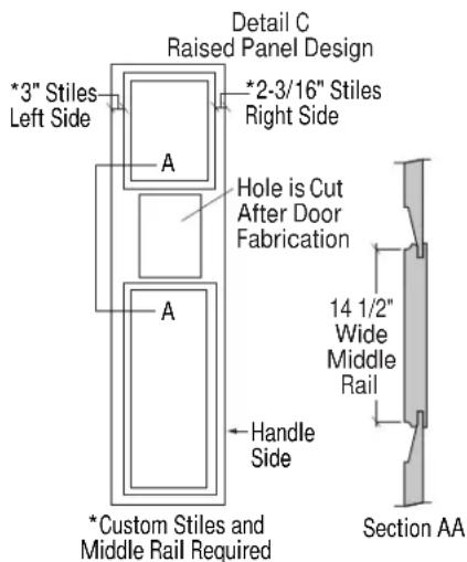
- For custom dispenser trim ZWCD1 kit must be used: Cut panels to size, refer to detail B for dispenser cutout routing instructions and install. When a raised panel design is used, a custom middle rail is required. A 14-1/2" wide middle rail must be used because the custom collar trim must be located within the raised portion of the panel. This area must be 3/4" thick. See detail C for raised panel design requirements.
text_image
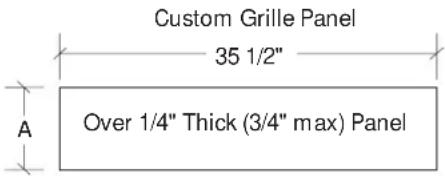
Custom Grille Panel 35 1/2" Over 1/4" Thick (3/4" max) PanelGrille Panel height can vary to fill installation height.
| Installation Height Dimension A | |
| 83" 8-1/4" | |
| 83-1/2" 8-3/4" | |
| 84" 9-1/4" | |
| 84-1/2" 9-3/4" | |
Important: Maintain 1-1/2" min. gap between top of doors and bottom of grille panel.
text_image
Detail C Raised Panel Design *3" Stiles Left Side A *2-3/16" Stiles Right Side Hole is Cut After Door Fabrication A Handle Side *Custom Stiles and Middle Rail Required 14 1/2" Wide Middle Rail Section AACustom Door Panel Dimensions
Using Trim Kit ZKT36
3/4" thick panel with custom handle and/or ZWCD1 custom collar trim


text_image
Freezer Panel Custom Dispenser 17 11/16" 67 15/16" 2 9/16" 15 5/16" Fresh Food Panel 19 5/16"Important: Maximum weight for fresh food panels is 50 pounds and 30 pounds for freezer door panels.
text_image
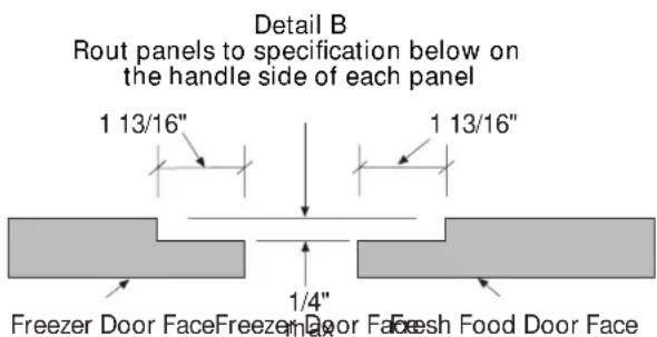
Detail B Rout panels to specification below on the handle side of each panel 1 13/16" 1 13/16" 1/4" Freezer Door Face Freezer Door Face Fresh Food Door FaceDetail C Custom Dispenser Cutout

text_image
9 7/16" 12 5/16" 7/8" Wide RoutThe Cutout is 9 7/16" wide by 12 5/16" high. 3/4" panels must be routed on all four sides of the cutout. Rout the back side of the panel 1/4" deep. 7/8" wide (shaded area).
ZISW36D (white dispenser) ZISB36D (black dispenser)
- ZKT36 and ZKHT1 installed together provides for the installation of 3/4" custom door and grille panels, using a custom handle of your choice. Cut panels to size, rout the handle side of the panels as shown below and install (see detail B).
- For ZKHTSS1 tubular stainless steel handle kit, cut panels to size and rout the handle side of the panels as shown in detail B.
- For standard dispenser trim: Cut panels to size, rout the handle side of the panels as shown in detail B, rout the bottom of the upper freezer panel and the top of the lower freezer panel to allow placement of support brackets (see detail A) and install.
- For custom dispenser trim ZWCD1 kit must be used: Cut panels to size, refer to detail C for dispenser cutout routing instructions. When a raised panel design is used, a custom middle rail is required. A 14-1/2" wide middle rail must be used because the custom collar trim must be located within the raised portion of the panel. This area must be 3/4" thick. See detail D for raised panel design requirements.
- When using the standard full-width dispenser trim, the length of the custom handle, top to bottom cannot exceed 11-3/4". Locate the handle a minimum of 3/4" and a maximum of 1-1/2" from the edge of the panel. There are no length restrictions on handles for models using a custom collar dispenser trim (ZWCD1).
Custom Grille Panel

text_image
35 1/2" Over 1/4" Thick (3/4" max) Panel AGrille Panel height can vary to fill installation height.
| Installation Height Dimension A | |
| 83" 8-1/4" | |
| 83-1/2" 8-3/4" | |
| 84" 9-1/4" | |
| 84-1/2" 9-3/4" | |
Important: Maintain 1-1/2" min. gap between top of doors and bottom of grille panel.

text_image
Detail D Raised Panel Design *3" Stiles Left Side A *2-3/16" Stiles Right Side Hole is Cut After Door Fabrication A Handle Side *Custom Stiles and Middle Rail Required 14 1/2" Wide Middle Rail Section AASide Panel or Filler Options (not to scale)
Side panels must be used whenever the sides of the refrigerator will be exposed.
1/4" Side Panels Insert end of side panel into trim.

text_image
Top View Trim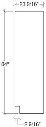
text_image
23 9/16" 84" 2 9/16"Standard 4" high toekick or trim to fit. Height may vary depending on application.
For All Monogram Built-In Refrigerators
1/2" to 3/4" Side Panels Leading Edge Flush with Cabinet Front. The front or leading edge, must be finished to match cabinetry.

natural_image
Top view diagram of a mechanical or architectural component with no visible text or symbols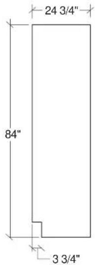
text_image
24 3/4" 84" 3 3/4"Standard 4" high toekick or trim to fit. Height may vary depending on application.
1/2" to 3/4" Side Panels Recessed front edge.
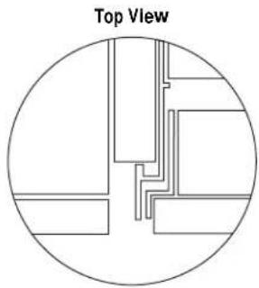
natural_image
Top view diagram of a circular architectural or structural layout with internal lines and blocks (no text or symbols)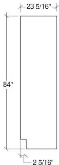
text_image
23 5/16" 84" 2 5/16"Standard 4" high toekick or trim to fit. Height may vary depending on application.
Installation
| 36" Built-In Refrigerator | |||
| Tools Required | Tinsnips to cut bandingStepladder1-1/2" open-end wrench | BucketLevelAppliance Hand TruckTubing cutter | 7/16" open-end wrench#2 Phillips screwdriverStubby Phillips screwdriverDrill and appropriate bits7/16" socket with 3" extension for ratchetSafety glasses |
| Hardware Supplied | Special velcro adhesive strips for 1/4" side panels | 1/4-1/4 union with nuts1/4" panel foam spacers | |
| Materials Required | Water shut-off valve (optional but recommended)Custom panels for fresh food, freezer compartments, grille panelSide panels | Hardware for side panel installation.36" long 2x4 for Anti-Tip support | |
| Flooring | For proper installation, this refrigerator must be placed on a level surface of hard material that is at the same height as the rest of the flooring. This surface should be strong enough to support a fully loaded refrigerator. | Note: Protect the finish of the flooring. Cut a large section of the cardboard carton and place under the refrigerator where you are working. | |
| Grounding the Refrigerator | IMPORTANT - (Please read carefully)FOR PERSONAL SAFETY, THIS APPLIANCE MUST BE PROPERLY GROUNDED.The power cord of this appliance is equipped with a three-prong (grounding) plug which mates with a standard three-prong (grounding) wall receptacle to minimize the possibility of electric shock hazard from this appliance.Have the wall outlet and circuit checked by a qualified electrician to make sure the outlet is properly grounded.Where a standard 2-prong wall outlet is encountered, it is your personal responsibility and obligation to have it replaced with a properly grounded 3-prong wall outlet.DO NOT, UNDER ANY CIRCUMSTANCES, CUT OR REMOVE THE THIRD (GROUND) PRONG FROM THE POWER CORD.Use of Adapter plugBecause of potential hazards under certain conditions, we strongly recommend against use of an adapter plug. However, if you still elect to use an adapter, where local codes permit, a TEMPORARY CONNECTION, may be made to a properly grounded 2-prong wall outlet by use of a UL listed adapter available at most hardware stores.The larger slot in the adapter must be aligned with the larger slot in the wall outlet to provide proper polarity in the connection of the power cord. | CAUTIONAttaching the adapter ground terminal to a wall outlet cover screw does not ground the appliance unless the cover screw is metal, and not insulated, and the wall outlet is grounded through the house wiring. You should have the circuit checked by a qualified electrician to make sure the outlet is properly grounded.When disconnecting the power cord from the adapter, always hold the adapter in place with one hand and pulling the power cord with the other hand. If this is not done, the adapter ground terminal is very likely to break with repeated use.Should the adapter ground terminal break, DO NOT USE the appliance until a proper ground has again been established.Use of Extension CordsBecause of potential safety hazards under certain conditions, we strongly recommend against the use of an extension cord. However, if you still elect to use an extension cord, it is absolutely necessary that it be a UL listed 3-wire grounding type appliance extension cord having a grounding type plug and outlet and that the electrical rating of the cord be 15 amperes (minimum) and 120 volts.PRUDENCEFICHE D'ADAPTATION(Fiches d'adaptation non permises au Canada) | |
Step 1 Remove Packaging
CAUTION
Refrigerator is much heavier at the top than at the bottom – be careful when moving. When using a hand truck, handle from side only.
PRUDENCE
- Remove outer carton.
- Carefully cut banding at the top and bottom.
- Slide out back corner posts (2).
- Slide carton off top of cabinet.
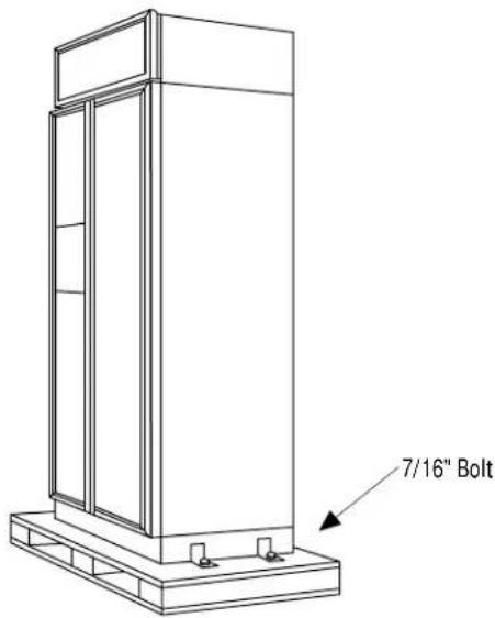
NOTE: IT IS NOT NECESSARY TO LAY CABINET DOWN IN ORDER TO REMOVE SKID! - To remove skid, remove the four 7/16" bolts and their brackets.
CAUTION
DO NOT ATTEMPT TO ROLL UNIT OFF SKID.
PRUDENCE
IL NE FAUT PAS ESSAYER DE FAIRE ROULER LE RÉFRIGÉRATEUR POUR L'ENLEVER DE LAY PALETTE.
text_image
7/16" Bolt- There are support blocks on the bottom of the cabinet and door. They must be removed before sliding unit off the skid or damage will occur.
- Carefully, tilt cabinet and slide blocks out from beneath cabinet, slide unit off skid.
- Remove toekick from fresh food compartment and set aside for later installation.
Step 2 Install Water Line
- A cold water supply is required for automatic icemaker operation. The water pressure must be between 40 and 120 p.s.i.
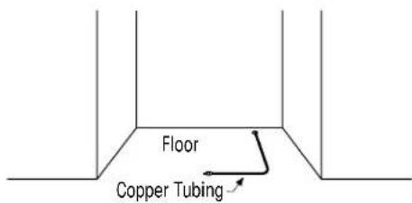
- Route 1/4" OD copper tubing between house cold water line and the water connection location.
• Copper tubing should be long enough to extend to the front of the refrigerator. Allow enough to accommodate bend leading into the water valve.
Shut off the main water supply.
Turn on the nearest faucet long enough to clear the line of water.
• Install a shut-off valve between the icemaker water valve and cold water pipe in a basement or cabinet. The shut-off valve should be located where it will be easily accessible.
NOTE: It is best to install the valve into a vertical water pipe. If you install the valve into a horizontal water pipe, make the connection at the top or side, rather than at the bottom, to avoid drawing off any sediment from the water pipe.
- Drill a 1/4" hole in the water pipe.
- Fasten the shut-off valve to the pipe with pipe clamp.
- Tighten the clamp screws until the sealing washer begins to swell. Do not over tighten.
- Place a compression nut and ferrule (sleeve) onto the end of the tubing and connect it to the shut-off valve. Make sure the tubing is fully inserted into the valve and ferrule is tightened.
- Turn on the main water supply and flush debris from the line. Run about a quart of water through the tubing into a bucket. Shut off water supply at the shut-off valve.
text_image
Floor Copper Tubing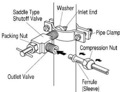
text_image
Saddle Type Shutoff Valve Packing Nut Outlet Valve Washer Inlet End Pipe Clamp Compression Nut Ferrule (Sleeve)NOTE: Saddle type shut-off valves are included in many water supply kits. Before purchasing, make sure a saddle type valve complies with your local plumbing codes.
NOTE: Commonwealth of Massachusetts Plumbing Codes 248CMR shall be adhered to. Saddle valves are illegal and use is not permitted in Massachusetts. Consult with your licensed plumber.
Step 2A For Installations With A Reverse Osmosis System Only
Skip This Step When Not Using RO System
WARNING
When connecting a GE Reverse Osmosis Water System to your refrigerator, the only approved installation is with a GE RVKIT.
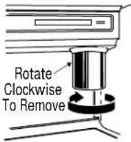
If the water supply to the refrigerator is from a Reverse Osmosis Water System AND the refrigerator also has a water filter, use the refrigerator's filter bypass plug. Using the refrigerator's water filtration cartridge in conjunction with the RO filter can result in hollow ice cubes and slower water flow from the water dispenser.
text_image
Rotate Clockwise To Remove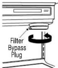
text_image
Filter Bypass PlugIf you use the bypass Plug and want a light shield without the filter opening, order a replacement solid light shield WR02X3025.
ATTENTION
- Side panels are not required when the refrigerator is installed into an enclosure. Skip this step if you are installing in an enclosure.
- Side panels are required whenever the sides of the refrigerator will be exposed and when installed between frameless cabinets. See pages 3 and 4.
- Side panel installation will be determined by the design of the side panel you have previously chosen.
-
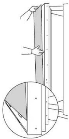
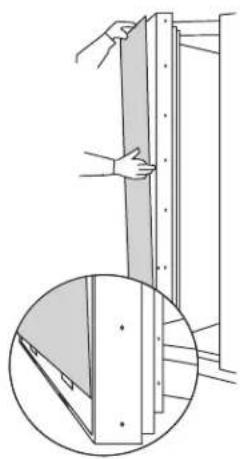
Side panels must be installed plumb.
-
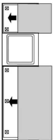
If you choose to use 1/4" side panels, they should be inserted into the case trim as illustrated. Fasten the panels to the refrigerator with Velcro strips (provided) before setting refrigerator in place. See illustration A.
- 1/2" to 3/4" side panels are normally set into place and fastened to adjacent cabinetry or the back wall before rolling the refrigerator into the opening. See illustrations B and C.

text_image
Side Panel Refrigerator Cabinet Refrigerator door1/4" Side Panels – Insert End Of Side Panel Into Case Trim. Fasten With Velcro Strips provided.

text_image
Illustration BIllustration A Refrigerator Cabinet Refrigerator door1/2" to 3/4" Side Panels – Leading Edge Of Side Panel Is Flush With Cabinet front. Fasten To The Back Wall Using A Cleat.

text_image
Illustration C Refrigerator Cabinet Cabinet Refrigerator door1/2" to 3/4" Side Panels – Recessed Front Edge of Side Panel. Fasten To Adjacent Cabinet.
Step 4 Roll Refrigerator Into Opening
- Gently push refrigerator into opening with hands against front corners. The cardboard protective pad should be beneath the refrigerator.
- Roll refrigerator into the opening until it is flush with adjacent cabinets.
Step 5 Level Refrigerator
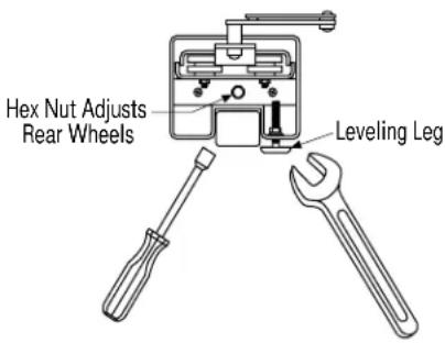
All models have 4-point leveling. The front is supported by leveling legs, the rear is supported by wheels.
- To level the back of the refrigerator, turn the 7/16" hex nut located above the front wheels. Turn to raise or lower the refrigerator.
- For front leveling, use a 1-1/2" open-end wrench.
- Adjust carefully, the refrigerator should be level and plumb with cabinetry, and should align with toekick height.
text_image
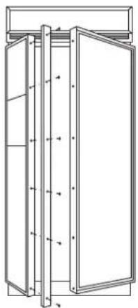
Hex Nut Adjusts Rear Wheels Leveling LegStep 6 Install 1/4" Door Panels
If you are using 3/4" thick custom panels, SKIP THIS STEP. See Custom Panel Dimensions pages for panel sizes with ZKT36 trim kit and other kits. Refer to trim kit installation instructions in this booklet.
If you are using the custom collar dispenser trim, order ZWCD1 trim kit.
To install 1/4" door panels:
- Open door to 90^ stop. Remove the Phillips head screws from the aluminum trim door handles. Retain all screws.

natural_image
Technical line drawing of a vertical cabinet or enclosure with multiple doors and structural beams (no text or symbols)
natural_image
Simple line drawing of a two-decker cabinet with no text or symbols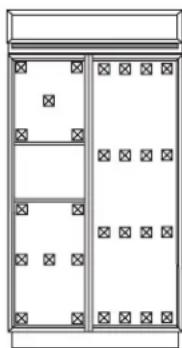
natural_image
Simple line drawing of a two-panel cabinet or enclosure with no text, numbers, or symbols- Attach 2" x 2" adhesive backed foam pads to the door. These fillers are shipped with literature package in snack pan.
- Slide panel into the door trim.
- Replace door handles and secure with original screws.
- Again, check to be sure unit is level and that panels align with cabinetry. Doors will not close properly if unit is not level.
- Check for noises caused by incomplete alignment (rubbing of panels, trim or screws).
natural_image
Pure diagram of two rectangular blocks with arrows indicating direction, no text or symbols present
natural_image
Line drawing of a person installing or adjusting a door panel (no text or symbols)Step 7 OPTION 1 Secure refrigerator at the top
WARNING
ANTI-TIP PRECAUTIONS
The refrigerator is heavy at the top and must be secured to prevent the possibility of tipping forward.
ATTENTION
PRECAUTIONS CONTRE LES BASCULEMENTS
To prevent the refrigerator from tipping over, you must: • Install a wood block, the full width of the refrigerator. Secure the block with wood screws penetrating at least 3/4" into wall studs.
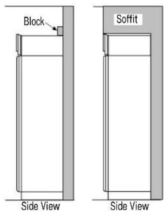
text_image
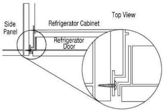
Block Soffit Side View Side ViewOPTION 2 Secure refrigerator at the sides
When using 1/2" to 3/4" side panels, the front flange of the case trim is attached to the side panel.
- Open freezer door to access case trim.
- Drill hole in case trim slightly below top hinge. Drive screw through the trim and into the side panel.
- Follow the same procedure on the fresh food side.
OR
If refrigerator is installed between cabinets with no side panels or in a custom enclosure, install a spacer block as shown.
- Open freezer door to access case trim.
- Drill hole in case trim slightly below top hinge. Drive screw through the trim and into the spacer block.
- Follow the same procedure for fresh food side.
text_image
Side Panel Refrigerator Cabinet Top View Refrigerator Door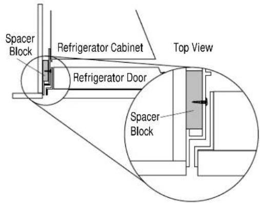
text_image
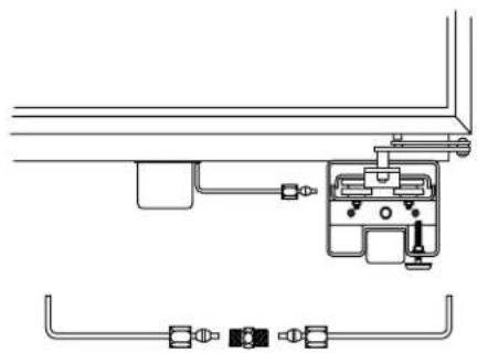
Spacer Block Refrigerator Cabinet Top View Refrigerator Door Spacer BlockStep 8 Connect Water Supply
Check to be sure that refrigerator power cord is not plugged into the wall outlet.
- Locate and bring copper tubing to the front of the cabinet.
- Turn the water on to flush debris from line, run about a quart of water through tubing into a bucket, then shut-off water.
- Slip a 1/4-1/4 union nut (provided) over both ends of the copper tubing at the right front leg of then refrigerator and couple the lines.
- Turn on the water to check for leaks.
natural_image
Pure mechanical diagram showing pipe connections and a central component (no text or symbols)Step 9 Connect power
- Connect refrigerator power cord plug to properly grounded receptacle, accessible through the top right side of the grille opening.
- Check to make sure power to refrigerator is on by opening refrigerator door to see if interior lights are on.

natural_image
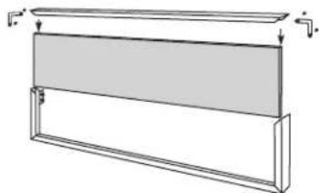
Line drawing of a cabinet with two doors and an electrical outlet (no text or symbols)Step 10 Mount Top Grille Panel
If you are using 3/4" thick custom panels, SKIP THIS STEP. SeeCustom Panel Dimensions for grille panel sizes. Order ZKT36 kit and follow the installation instructions packed with the kit.
The grille panel frame is factory assembled for an 84" installation height. If installation height varies, order ZG2 trim kit which provides optional side trim pieces.
Cut 1/4" thick custom panel to fit the frame, 35" wide, 9" deep.
To insert decorative grille panel into the frame:
- Remove screws (2 on each top corner) and "L" brackets on each side.
- Slide panel into the frame and reassemble.
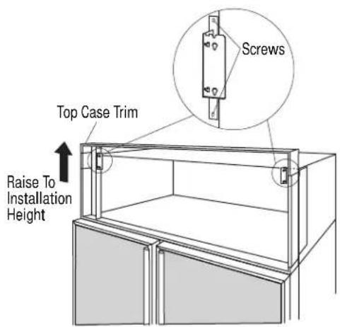
- Mount the grille panel by dropping into slots on the case trim.
For shipping purposes, the top case trim is secured at 84" installation height.
To raise or lower case trim to other installation heights:
- Loosen 2 screws on both sides and raise the top case trim to meet soffit height or to the top of adjacent cabinets.
- Tighten all 4 screws.
If installation height is more or less than 84", order ZG2 optional grille panel kit which accommodates 83", 83-1/2" and 84-1/2" heights. See installation instructions page 26.

text_image
Screws Top Case Trim Raise To Installation Height
natural_image
Pure technical line drawing of a rectangular frame with no text, numbers, or symbols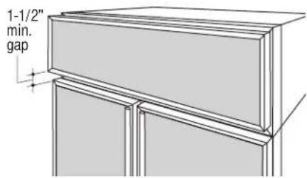
text_image
1-1/2" min. gap
natural_image
Line drawing of a cabinet or rack unit with no visible text or symbolsImportant. Maintain 1-1/2" min. gap between top of doors and bottom of panel frame.
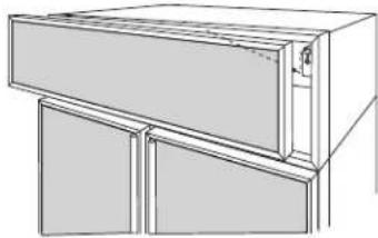
Step 11 Install Toekick
- A standard toekick is supplied. Install with 2 screws provided, adjust to desired height and tighten screws.
- A custom toekick can be installed to match or complement the surrounding cabinetry.
- If a custom toekick is to be installed, use the supplied toekick as a template to cut out notches around hinges and waterline tubing.
- For 1/2" to 3/4" thick custom toekicks, additional material should be removed and cut away. This will allow the water and electrical umbilical tube to rotate smoothly when the door is fully opened.
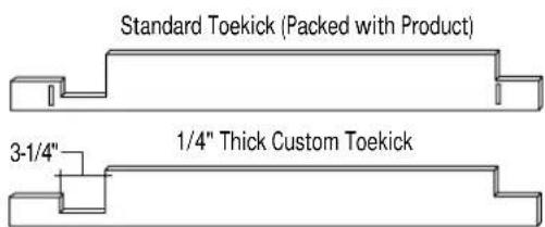
text_image
Standard Toekick (Packed with Product) 3-1/4" 1/4" Thick Custom Toekick1/2" to 3/4" Thick Custom Toekick Remove Additional Material

text_image
4-1/16"Tools and materials required:
• #2 Phillips screwdriver
- Drill and appropriate bits
- Custom door panels
- Custom handles
- Safety glasses
These instructions are divided into 2 options: Option 1—For non-dispenser and dispenser models using custom collar trim. Option 2—For dispenser model using the standard full-width trim.
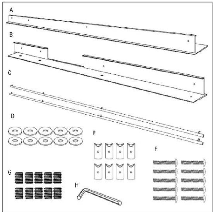
Kit contents
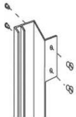
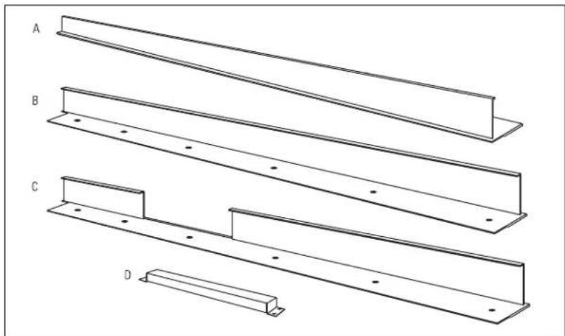
Parts List:
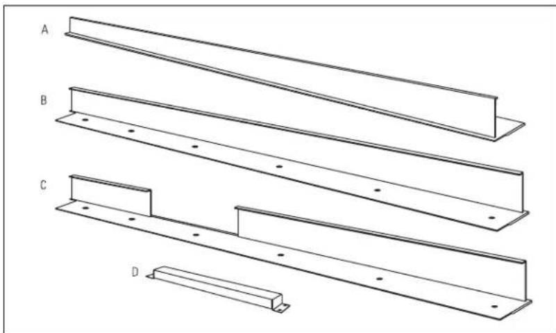
A. Fresh food door extrusion
B. Freezer door extrusion for non-dispenser model and dispenser model using custom collar. (Option 1)
C. Freezer door
extrusion for
dispenser model
using full-width trim.
(Option 2)
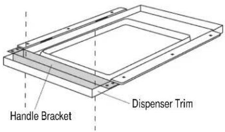
D. Handle bracket for dispenser model using full-width trim.
(Option 2)
natural_image
Technical line drawing of four structural beams labeled A, B, C, and D (no text or symbols on the beams themselves)This kit provides the necessary framework to install custom handles, of your choice, onto 1/4" thick decorator door panels. (Handles not included.) The door extrusions and bracket allow custom handles to be secured to the door structure, rather than the door panels. This kit contains all the necessary parts for
dispenser and non-dispenser models. Follow the instructions for Option 1 when applying custom handles to a non-dispenser model or dispenser model using custom collar trim. Follow instructions in Option 2 for a dispenser model using the standard full-width dispenser trim.
OPTION 1 For non-dispenser model or dispenser model using custom collar trim
Step 1 Remove handles
- Open doors to 90^ . Remove the screws from the full-length aluminum handles of both doors.
- Retain screws, discard handles.
Note: If a custom collar is to be used, order ZWCD1 Trim Kit.

natural_image
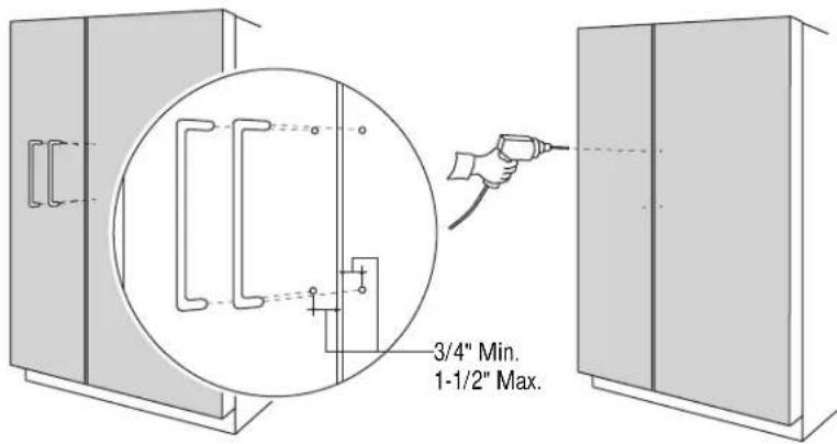
Technical line drawing of a cabinet or enclosure with vertical supports and a top shelf (no text or symbols)Step 2 Locate position of handles
text_image
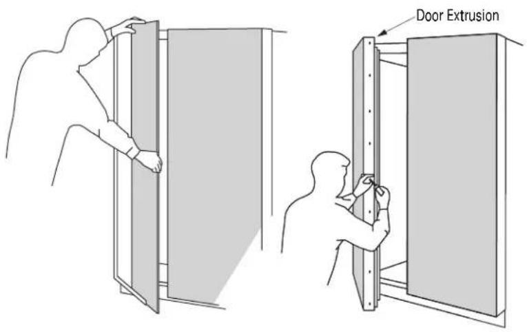
Door Extrusion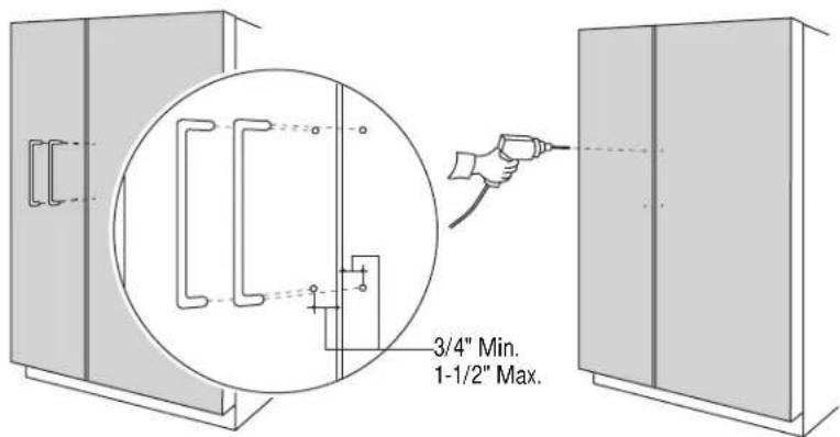
text_image
3/4" Min. 1-1/2" Max.Note: Handle must be located 3/4" to 1-1/2" from edge of extrusion.
- Slide custom panels into fresh food and freezer door frames.
• Temporarily secure the new door extrusions to the doors. Use at least 2 screws on each door. - The handles must be located 3/4" to 1-1/2" from the edge of the extrusion.
-
Determine the desired location of the custom handles and carefully mark centerlines of the screw holes.
-
Again, with both doors closed, check the location of the centerlines to be sure they are parallel to the edge of the door, and level with opposite door.
- Drill 1/16" pilot hole through the panel until it starts into the aluminum extrusion. This will mark the matching location for drilling the clearance hole when assembling the handle, panel and extrusion.
Step 3
Assemble panel,
extrusion and
handle
- Remove the door extrusions and door panels.
- Drill 1/16" pilot hole through extrusion.
- Drill clearance holes through the panel and extrusion.
- Assemble the door panel, extrusion and custom handle.
• Install screw(s) long enough to pass through the extrusion, door panel and into the handle. - Slide the assembly into the door frame until the new extrusion fits firmly against the steel door.
- Re-install original screws into the door extrusion.
OPTION 2
For dispenser model using full-width trim
Step 1
Remove handles
- Open door to 90^ . Remove the screws from the full-length aluminum handle of the freezer door.
- Retain screws, discard handle.
natural_image
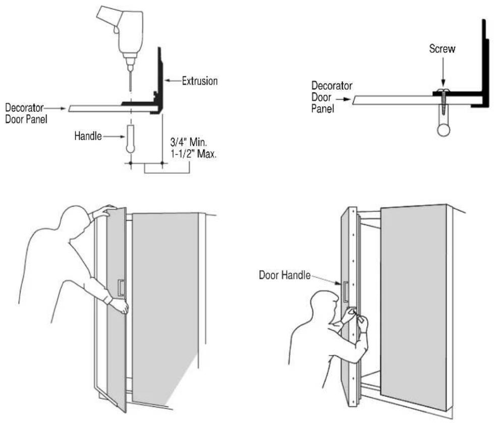
Technical line drawing of a cabinet or enclosure with vertical structural elements and mounting brackets (no text or symbols)Step 2
Remove trim
Remove door panel trim above and below dispenser. Lift off dispenser trim. Retain screws and trim.

text_image
Remove Trim Remove Dispenser TrimStep 3
Locate position
of handle
- Position the handle bracket onto the steel door by matching existing screw holes on the door and bracket. Temporary secure with screws.
• Re-install dispenser trim, temporarily. - Determine the desired location of the custom handle and carefully mark centerlines of the screw holes.
- Drill 1/16" pilot hole through the trim until it starts into the handle bracket. This will mark the matching location for drilling a clearance hole when assembling the handle, bracket and dispenser trim.
- Remove dispenser trim and bracket.
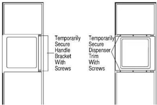
text_image
Temporarily Secure Handle Bracket With Screws Temporarily Secure Dispenser Trim With Screws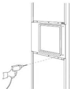
natural_image
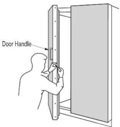
Line drawing of a hand holding a tool near a wall-mounted panel (no text or symbols)Step 4 Install custom handle
- Drill clearance holes through the handle bracket and the dispenser trim.
• Install screw(s) long enough to pass through the handle bracket, dispenser trim and into the custom handle.

text_image
Handle Bracket Dispenser TrimNote: The custom handle must be installed against the handle bracket. The custom handle cannot exceed 11-3/4" length.

text_image
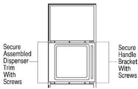
Handle Bracket Dispenser Trim Custom HandleStep 5 Mount assembled dispenser trim
- Mount assembled dispenser trim with handle onto the door.
- Drive 2 screws through the top and bottom of the handle bracket into the steel door.
- Re-install 3 screws at top and bottom of dispenser trim.
Important: The handle bracket must be secured to the steel door. If it is not secured properly, the dispenser trim will pull away from the door.
text_image
Secure Assembled Dispenser Trim With Screws Secure Handle Bracket With ScrewsStep 6 Install custom handle extrusion
- Slide decorator panels into the trim, top and bottom.
- Slide freezer door extrusion in between panels and steel door. Secure with screws.
- To install fresh food handle follow the same procedure as shown in Option 1.
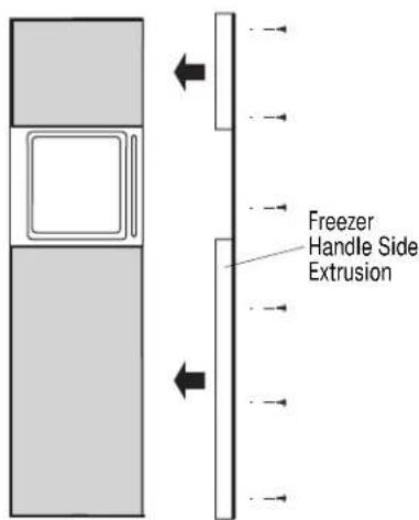
text_image
Freezer Handle Side ExtrusionFOR 83", 83-1/2" AND 84-1/2" INSTALLATION HEIGHTS
- This kit provides optional side trim pieces for the original grille frame to fit 83", 83-1/2" or 84-1/2" installation heights.
To change grille panel size:
- Determine the installation height by measuring the enclosure from the floor to the underside of soffit. When there is no soffit, measure to the top of adjacent cabinets.
- Adjust refrigerator case trim to desired height. See Production Installation.
- Select the side trim pieces for your installation height.
| Installation Panel Side Trim Panel Height Width Lengths Height | ||
| 83" 35" 8-1/4" 8" | ||
| 83-1/2" 35" 8-3/4" 8-1/2" | ||
| 84-1/2" 35" 9-3/4" 9-1/2" |

text_image
Barrel Nuts Discard Side Trim PiecesA. Locate original grille panel frame supplied with the refrigerator.
- Remove 8 screws (two on each corner) as illustrated. Discard original side trim pieces.
B. Select correct size of side trim pieces (3 sets provided). - Secure new side trim pieces to original bottom trim.

C. Remove barrel nuts from original side trim pieces (2 each side).
- Re-install the barrel nuts on the new side trim pieces you have selected.
natural_image
Pure technical line drawing of a rectangular frame with no text, numbers, or symbolsD. Slide custom panel into front slots.
- Secure the top trim piece to the frame with "L" brackets and screws.
natural_image
Line drawing of a cabinet or rack unit with three doors and a door, no text or symbols presentE. Mount the assembled panel by dropping into slots on the case trim.

text_image
1-1/2" min. gapImportant: Maintain 1-1/2" min. gap between top of doors and bottom of grille panel.
Note: ZG1 Grille Panel Kit is available for models produced before January 1997. Panel sizes for ZG1 and ZG2 are the same. The ZG1 kit can be ordered from your Monogram dealer.
Tools and materials required:
• #2 Phillips screwdriver
- Stubby Phillips screwdriver
- Drill and appropriate bits
- Safety glasses
- Custom panels
These instructions are divided into 2 options:
Option 1—For non-dispenser and dispenser models using custom collar trim.
Option 2—For dispenser model using the standard full-width trim.
Kit contents
Parts List:
Freezer Door
A. Top trim
B. Side trim
C. Bottom trim
Fresh Food Door
D. Top trim
E. Side trim
F. Bottom trim
G. Panel support brackets (4)
H. 4-3/8" screws for support brackets (20)
I. Grille support panel and screws ZKT36–6 screws
J. Wood screws #6 1/2" flat-head screws ZKT36-30 screws
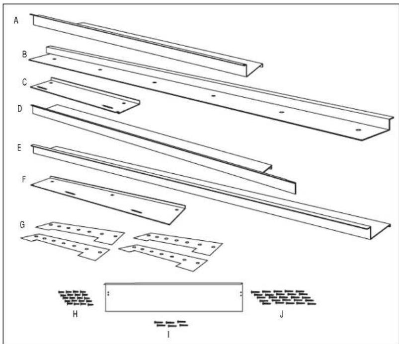
text_image
A B C D E F G H I JThis kit provides for the installation of 3/4" custom door and grille panels, using the standard full length handle. This kit contains all the necessary parts to apply 3/4" panels on dispenser and non-dispenser models. Follow the instructions for Option 1 when applying custom panels to a non-dispenser model or dispenser model using custom collar trim. Follow instructions in Option 2 for a dispenser model using the standard full-width dispenser trim.
Note: If you are using custom handles, see ZKHT1 Installation Instructions. For tubular stainless steel handles, see ZKHTSS1 Installation Instructions.
OPTION 1
For non-dispenser model
or dispenser model using custom collar trim
Step 1
Remove
handles & trim
- Open door to 90^ .
- Remove the Phillips head screws from the full-length handles.
- Open the doors fully to stop.
- Remove the screws from the aluminum trim, top, bottom and hinge side.
- Retain screws. Discard original trim.
Note: If a custom collar is to be used, order ZWCD1 trim kit. If a custom handle is to be used, order ZKHT1 trim kit.
Important: When the bottom trim piece is removed, an aluminum shim secured to the bottom of the door can be seen. Do not attempt to remove this piece.

natural_image
Technical line drawing of a cabinet or enclosure with vertical supports and doorways (no text or symbols)Step 2
Install
3/4" trim
- Attach the new 3/4" trim pieces on the top, hinge side and bottom using original screws.
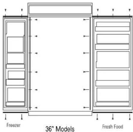
text_image
Freezer 36" Models Fresh FoodStep 3
Apply panel
support brackets
Dimension A ZKT36-6-3/4"
Dimension B
ZKT36-7-7/8"
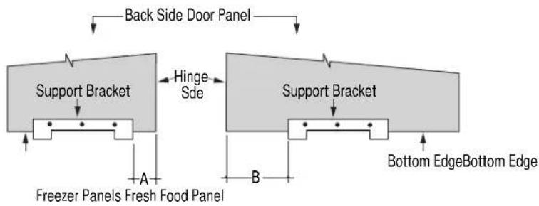
flowchart
graph TD
    A["Back Side Door Panel"] --> B["Support Bracket"]
    B --> C["Hinge Side"]
    C --> D["Support Bracket"]
    D --> E["Bottom Edge"]
    D --> F["Bottom Edge Bottom Edge"]
    G["Freezer Panels Fresh Food Panel"] --> H["A"]
    H --> I["B"]
    I --> J["Bottom Edge"]
    style A fill:#f9f,stroke:#333
    style D fill:#f9f,stroke:#333
    style G fill:#ccf,stroke:#333
- Position support bracket on freezer panel, dimension A, from the hinge side edge.
-
Position support bracket on fresh food panel, dimension B, from the hinge side edge.
-
Secure support brackets to the bottom of the panels with #4 screws provided. Align the brackets flush with the bottom of the panels, with tabs protruding below.
- Bracket location measured from the hinge side, is the same for panels with custom handles or standard handles.
Step 4
Install panels

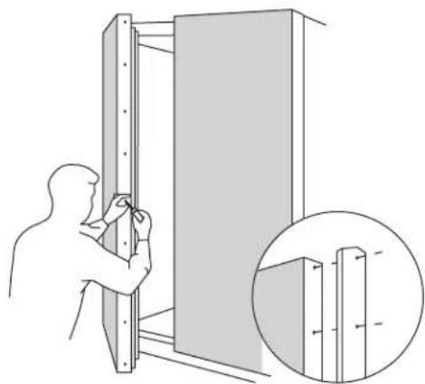
natural_image
Diagram showing a hand holding a vertical panel with a close-up inset of the same panel detail (no text or symbols)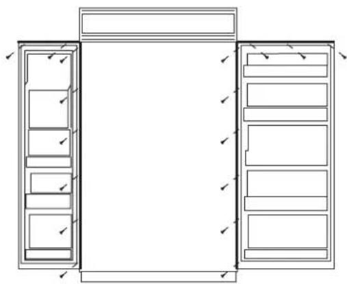
natural_image
Architectural line drawing of a two-story cabinet with drawers and doors, no text or symbols presentZKT36 – Install 17 screws
- Place the 3/4" panel on the bottom trim with support bracket tabs inserted into slots. Push the panel back against the steel door, making sure panel is flush to hinge side trim.
- Carefully drill starter holes in panel using a small drill bit.
- Attach the panel to the top and hinge side by installing screws from the back of the trim through the wood panel.
- Follow the same procedure to install fresh food door panel.
- Re-install door handles with original screws.
natural_image
Illustration of a person installing or adjusting a wall-mounted panel, with an inset showing close-up details (no text or symbols)Step 5
Adjust
grille panel height
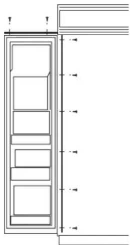
The refrigerator is shipped with the top case trim secured at the 83" refrigerator height.
- Loosen 2 screws on both sides and raise the top case trim to meet soffit height, from 83" to 84-1/2".
- Tighten all 4 screws.
Important: Maintain 1-1/2" min. gap between top of doors and bottom of grille panel.
text_image
Screws Top Case Trim Raise To Installation HeightStep 6
Secure 3/4" panel to grille panel support
- Secure the new grille panel support to the back side of the 3/4" panel with #6 screws.
- Be sure the lip on the support panel is over the top of the wood panel.

text_image
Panel Support Overlaps Top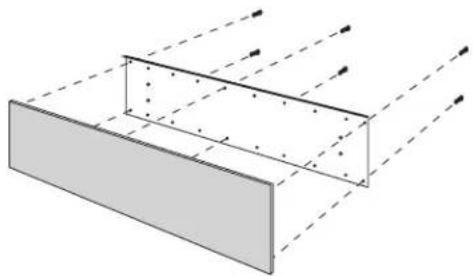
natural_image
Diagram of a rectangular structure with dashed light rays passing through it, no text or symbols presentStep 7
Install
grille panel
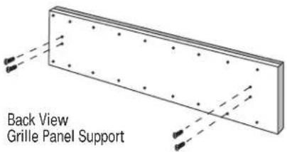
text_image
Back View Grille Panel Support
text_image
1/16"- Install four of the six larger under cut screws such that the top of the screws are 1/16" from the surface of the support.
- Attach the assembled panel to the grille frame by inserting the four protruding screws into brackets located on each side of the grille frame.
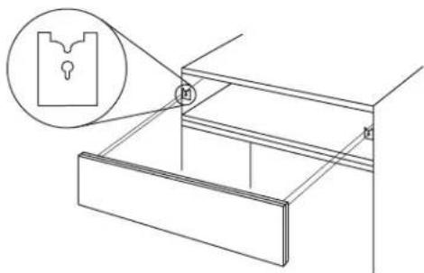
natural_image
Technical line drawing of a mechanical assembly with a magnified inset showing a keyhole (no text or symbols)OPTION 2
For dispenser model using full-width trim
Step 1
Remove handles & trim
- Open freezer door to 90^ .
- Remove the Phillips head screws from the full-length handles.
- Open door fully to stop.
- Remove screws from the aluminum trim, top, bottom and hinge side.
- Remove the trim above and below the dispenser.
- Retain screws and full-length handles. Discard original trim.

natural_image
Technical line drawing of a vertical cabinet or enclosure with multiple doors and structural ribs (no text or symbols)Step 2
Install 3/4" trim
- Attach the new 3/4" trim pieces at the top and hinge side using original screws.
natural_image
Architectural cross-section diagram of a building facade with horizontal and vertical dimension lines (no text or symbols)Step 3
Install panel support brackets
- Position and mark the location for the support brackets on the back side of the panels. Align all brackets flush with the end of the panels, with tabs protruding over the edge.
- On the bottom of the upper panel, measure dimension A from the hinge side.
- On the bottom of the lower panel, measure dimension B from the hinge side.
- On the top of the lower panel, measure dimension C from the hinge side.
- Secure all brackets with #4 screws provided.
Dimension A
ZKT36-4-3/8"
Dimension B
ZKT36-6-3/4"
Dimension C
ZKT36-4-3/8"
text_image
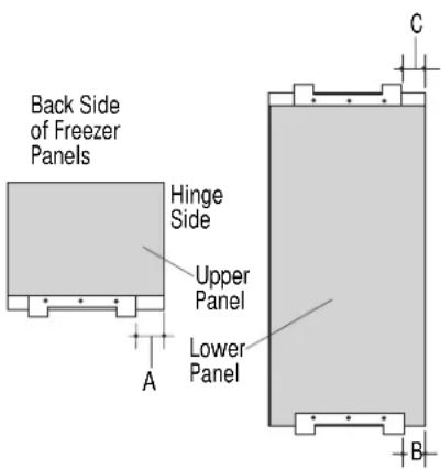
Back Side of Freezer Panels Hinge Side Upper Panel Lower Panel A C BStep 4 Install panels
text_image
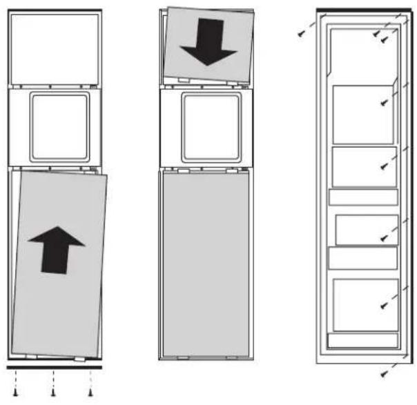
Diagram showing three vertical panels with arrows indicating direction, likely illustrating a layout or storage mechanism.• Install the lower panel by slipping tabs into the slots on the underside of the dispenser trim.
- Hold in position while fitting new bottom trim against the bottom of the door. Tabs should protrude through the bottom trim.
• Install screws up through the bottom trim using stubby Phillips screwdriver.
- Open door and install screws through the back side of the trim and into the panel at the hinge side.
- Place the upper panel onto the top of the dispenser with tabs inserted into the slots.
- Push the panel back against the steel door.
- Open door and install screws through the back of the trim and into the panel, at the top and hinge side.
Step 5 Install handles
• Install door handle using original screws.
• Install panel on fresh food door using the same procedure as in Option 1.
• Install grille panel using the same procedure as in Option 1.
natural_image
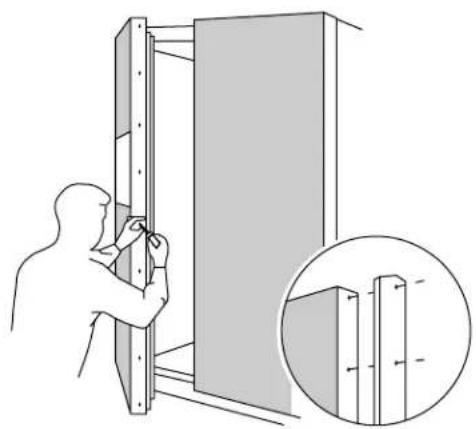
Illustration of a person installing or adjusting a wall-mounted panel, with an inset showing close-up details (no text or symbols)Tools and materials required:
• #2 Phillips screwdriver
- Stubby Phillips screwdriver
- Drill and appropriate bits
- Custom panels
- Custom handles
- Safety glasses
Note: This kit must be used in conjunction with ZKT36 trim kit for 3/4" panel trim.
These instructions are divided into 2 options:
Option 1—For non-dispenser and dispenser models using custom collar trim.
Option 2—For dispenser model using the standard full-width trim.
Kit contents
Parts List:
A. Fresh food door extrusion
B. Freezer door extrusion for non-dispenser model and dispenser model using custom collar. (Option 1)
C. Freezer door extrusion for dispenser model using full-width trim. (Option 2)
D. Freezer door handle bracket for dispenser model using full-width trim. (Option 2)
natural_image
Technical line drawing of four structural beams labeled A, B, C, and D (no text or symbols on the beams themselves)This kit provides the necessary framework to install custom handles of your choice, on 3/4" thick decorator door panels. (Handles not included.) The door extrusions and bracket allow custom handles to be secured to the door structure, rather than the door panels. This kit contains all the necessary parts for dispenser and non-dispenser models. Follow the
instructions in Option 1 when applying custom handles to a non-dispenser model or dispenser model using custom collar trim. Follow the instructions in Option 2 for a dispenser model using the standard full-width dispenser trim.
OPTION 1
For non-dispenser model
or dispenser model
using custom
collar trim
Before
you begin
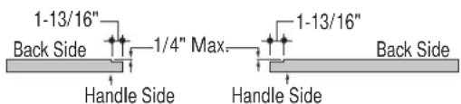
Note: Optimal final appearance depends on careful routing depth. Do not exceed 14 " routing depth.

text_image
1-13/16" Back Side 1/4" Max. Handle Side 1-13/16" Handle Side Back SideFreezer Panel Fresh Food Panel
3/4" custom door panels must be routed to accommodate these door extrusions. Rout the panels as illustrated, a maximum of 1/4" deep, and 1-13/16" wide, top to bottom on the handle side.
Refer to installation instructions for ZKT36 trim kit for 3/4" custom panels Option 1.
- Follow Step No. 1 to remove the standard aluminum trim.
- Follow Step No. 2 and 3 to attach new 3/4" trim pieces and install panel support brackets.
Step 1 Temporarily mount door panels
natural_image
Diagram showing a hand holding a vertical panel next to a close-up of a wooden structure with a shaded section (no text or symbols)
natural_image
Illustration of a person installing or adjusting a wall-mounted panel, with an inset showing close-up details (no text or symbols)- Place the prepared 3/4"custom door panels on the bottom trim with support bracket tabs inserted into slots.
-
Push the panel back against the steel door, making sure panel is flush with hinge side trim.
-
Secure the panel to the trim temporarily by driving 2 screws through the back side of the trim at the top.
- Slide door extrusion in between panel and steel door. Temporarily secure with 2 screws.
Step 2 Locate position of handles
text_image
3/4" Min. 1-1/2" Max.- Determine the desired location of the custom handles and carefully mark centerlines of the screw holes. The handles must be located 3/4" to 1- 12 " from the end of the extrusion.
- Again, with both doors closed, check centerlines of the screw holes to be sure they are parallel to the edge of the door, and level with opposite door.
- Drill 1/16" pilot hole through the panel until it starts into the aluminum extrusion. This will mark the matching location for drilling a clearance hole when assembling the extrusion, panel and handle.
Step 3 Assemble panel, extrusion and handle
- Remove the door extrusions and door panels.
- Drill 1/16" pilot hole through extrusion.
- Drill clearance holes through the panel and extrusion.
- Assemble the door panel, extrusions and custom handle.
• Install screw(s) long enough to pass through the extrusion, door panel and into the handle.

text_image
Screw 3/4" Min. 1-1/2" Max.Step 4
Mount
assembled
panels
natural_image
Diagram showing a hand holding a vertical panel with a magnified inset of the same panel detail (no text or symbols)
natural_image
Architectural line drawing of a double door with internal compartments and doorways (no text or symbols)- Place assembled panel onto bottom trim with support bracket tabs inserted into slots.
- Push the panel back against the steel door with door extrusion flush to the handle side of the door.
- Open door fully to stop.
• Install screws at the top, hinge side and end of door extrusion.
text_image
Door HandleOPTION 2
For dispenser
model using
full-width
trim
Note: Optimal final appearance depends on careful routing depth. Do not exceed 14 " routing depth.
text_image
1-13/16" Back Side 1/4" Max. Handle Side 1-13/16" Handle Side Back SideFreezer Panel Fresh Food Panel
Before
you
begin
All 3 custom door panels must be routed to accommodate the door extrusions. Route the panels as illustrated, max. 1/4" deep, 1-13/16" wide, top to bottom on the handle side.
Refer to installation instructions for ZKT36 trim kit, Option 2.
- Follow Step No. 1 to remove standard aluminum trim.
- Follow Step No. 2 and 3 to attach new 3/4" trim pieces and install panel support brackets.
Step 1
Locate position
of handle
Note: The custom handle must be installed against the handle bracket. The custom handle cannot exceed 11-3/4" length.

text_image
Temporarily Secure Handle Bracket With Screws Temporarily Secure Dispenser Trim With Screws- Position the handle bracket onto the steel door by matching existing screw holes on the door and bracket.
- Re-install dispenser trim, temporarily.
-
Determine the desired location of the custom handle and carefully mark centerlines of the screw holes.
-
Drill 1/16" pilot hole through the trim until it starts into the handle bracket. This marks the same location onto the bracket.
- Remove dispenser trim and bracket.
Step 2 Install custom handle
- Drill clearance holes through the handle bracket and the dispenser trim.
- Install screw(s) long enough to pass through the handle bracket, dispenser trim and into the custom handle.
text_image
Handle Bracket Dispenser Trim
text_image
Handle Bracket Dispenser Trim Custom HandleStep 3 Mount assembled dispenser trim
- Mount assembled dispenser trim with handle onto the door.
- Drive 2 screws through the top and bottom of the handle bracket into the steel door.
- Re-install 3 screws at top and bottom of dispenser trim.
Important: The handle bracket must be secured to the steel door. If it is not secured properly, the dispenser trim will pull away from the door.

text_image
Secure Assembled Dispenser Trim With Screws Secure Handle Bracket With ScrewsAgain, refer to ZKT36 trim kit, Option 2.
- Follow Step 4 to install freezer door panels and bottom trim.
- Slide freezer handle side extrusion in between panels and steel door. Secure with screws.
- To install fresh food handle, follow the same procedure as in Option 1.

text_image
Freezer Handle Side ExtrusionThis kit provides for the installation of Stainless Steel custom handles on 1/4" thick decorator door panels. The door extrusions allow these custom handles to be secured to the door structure, rather than to the custom panels. This kit contains all the necessary parts for dispenser and non-dispenser models.
Tools and materials required:
• #2 Phillips screwdriver
- Drill and 1/8", 9/32" bits
- Custom door panels
- Safety glasses
- Center punch
- Masking tape
- Hammer
- Pencil
- 1/2" thick 12" x 12" min. piece of plywood to protect floor when drilling
- For stainless steel panels wear gloves to protect against sharp edges.
Parts List:
A. Fresh food door extrusion
B. Freezer door extrusion
C.2 Stainless tubular handles
D. 10 Spacer rings (for Stainless panels ONLY) (8 required, 2 extra)
E. 8 Handle standoffs
F. 10 Screws for mounting handle standoffs (8 required, 2 extra)
G. 10 Set screws (8 required, 2 extra)
H. 3/32" Allen wrench for set screws
Note: It is best that 2 people install this kit.
text_image
A B C D E F G HStep 1: Remove Handles
- Open doors to 90^ . Remove the screws from the full-length handles of both doors.
- Retain screws, discard handles.
- Locate the 2" x 2" adhesive foam pads packed with the refrigerator. Apply pads to the doors as shown. Corner pads should be as close to inside corners as possible.
natural_image
Simple line drawing of a two-panel cabinet or enclosure with no text, numbers, or symbols
natural_image
Simple line drawing of a two-story cabinet with windows and doors (no text or symbols)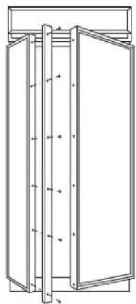
natural_image
Technical line drawing of a cabinet or enclosure with vertical supports and doorways (no text or symbols)Note: If a custom collar is to be used, order ZWCD1 Trim Kit for 36" and 42" wide models. Order ZWCD2 for 48" wide models.
Step 2:
Match
Handle Extrusions to Handle
FOR CUSTOM
WOOD
PANELS
See Step 2A
for Stainless
Steel panels
- Cut a piece of corrugated to use as a pad to protect the panel finish. Use 1/2" thick section of plywood to protect flooring when drilling.
- Place custom panels on the pad, appearance side down.
Note: If panels are wood, be sure to note which end is the top so that wood grain is in the correct direction on both (or all 3) panels.
- On the back side of the panel – at the handle side, measure and mark 1/4" below the top edge of the panel with a pencil.
- Slip panels into new extrusion on the handle side of the panels.
- Align the extrusion at the pencil mark, 1/4" below the top of the panel.
- Follow the same procedure on the opposite panel.
- Tape the extrusions to the panels to prevent movement.
- Center punch and drill 1/8" pilot holes through the holes in the extrusion and into the panel.
- Turn panel over. On the appearance side, use 9/32" bit to enlarge clearance hole.
IMPORTANT: Hole locations must be exact to accept handle standoff and handle assembly.
For models with full width dispenser trim and 2 piece freezer panels:
- Measure 1/4" from the top of the upper panel and 1/4" from the bottom of the lower panel. Mark with pencil on the back handle side.
- Align the extrusion on the pencil mark as shown, top and bottom.
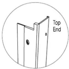
text_image
Top EndNote: Be sure to orient extrusions and handles correctly. The top ends of the extrusions are cutout to fit the shape of the top of the door.

flowchart
graph TD
    A["Freezer Upper Panel"] --> B["Models With Full Width Dispenser Trim"]
    C["Back Side Freezer Lower Panel"] --> B
    D["Back Side Freezer Panel"] --> E["Freezer Extrusion"]
    F["Back Side Fresh Food Panel"] --> E
    G["Fresh Food Extrusion"] --> E
    H["Align Extrusion 1/4" Below Top of Panel"] --> A
    H --> C
    H --> D
    H --> F
text_image
Decorator Door Panel ExtrusionStep 2A:
FOR STAINLESS STEEL PANELS
If you are installing these handles onto Stainless Steel panels:
Use extreme caution if you are drilling through stainless steel panels. Stainless panels must be handled gently. Do not kneel on stainless steel panels. It will leave a permanent dent. Do not remove protective plastic covering until final installation.
- Place supplied filler panel (corrugated) on floor to use as a pad.
- On the back side of the panel—at the handle side, measure and mark 1/4" below the top edge of the panel.
For models with full width dispenser trim and 2-piece freezer panels:
—Measure and mark 1/4" below the top edge of the upper panel.
-Measure and mark 1/4" above bottom edge of lower panel.
- Slip panels into the new extrusion, flush against inner edge, on the handle side.
- Align extrusion to pencil mark(s) as shown in Step 2. Mark each screw hole location with pencil.
- Tape extrusions to panels to prevent movement.
- Place panel on plywood section, appearance side down. Be sure plywood is clean without nicks and burrs. Center punch at each screw hole location.
- Drill 1/8" pilot hole. Use 9/32" bit to enlarge clearance hole.
- Measure and cut a 2" wide strip, top to bottom off the corrugated panels. This will allow room for spacer rings between the stainless panel and extrusion.
Step 3: Install Standoffs onto Handles
- Place a handle standoff on each attachment post along the handle. Position the set screw hole on each standoff to point to the floor.
- Install set screws into the bottom of each standoff, using the Allen wrench provided. The standoff should be tight against the handle.

text_image
Screw Allen WrenchStep 4: Install Handles and Panels
FOR CUSTOM WOOD PANELS
See Step 4A for Stainless Steel panels

natural_image
Pure diagram of three rectangular shapes with arrows indicating direction, no text or symbols present
natural_image
Line drawing of a person installing or adjusting a door panel (no text or symbols)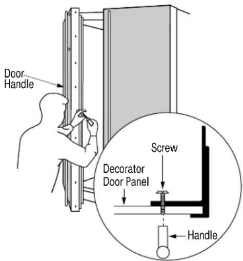
text_image
Door Handle Screw Decorator Door Panel Handle- Press foam pads against steel doors to temporarily reduce thickness.
- Slide panels into the door trim. Leave about 4" of the panel exposed to allow room to install the handle extrusion.
-
Place extrusion onto back side of panel, install mounting screws through the extrusion and the custom panel.
-
Screw handle to panel, starting at the top. Moving down the handle, drive each screw partially into the standoff, alternating back to the top until the handle is tight against the panel.
- Slide the assembly into the door frame until the extrusion fits firmly against the steel door.
- Reinstall original screws into the door extrusion.
Step 4A:
Install
Handles
and Panels
FOR
STAINLESS
STEEL
PANELS
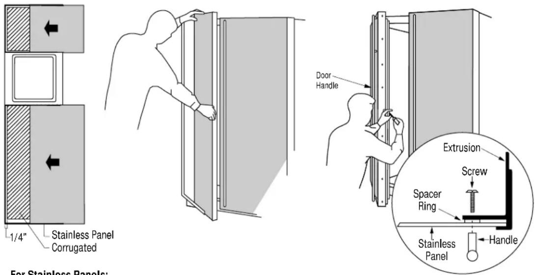
text_image
Stainless Panel Corrugated 1/4" For Stainless Panels: Door Handle Extrusion Screw Spacer Ring Stainless Panel HandleFor Stainless Panels:
- Press foam pads against steel doors to temporarily reduce thickness.
- Crimp top and bottom edges of corrugated.
- Slide corrugated onto doors, leave about 1/4" gap between edge of corrugated and hinge side.
Note: Panels have a protective plastic covering. Peel away just enough to allow panel to slide into trim and to clear handle mounting screws. The plastic covering will keep the panels clean during the installation process.
- Slide panels into the door trim. Leave about 4" of the panel exposed to allow room to install the handle extrusion.
Be sure to maintain 1/4" gap between corrugated and hinge side trim.
- Place a spacer ring over each of the 4 screw holes on the extrusion. Use tape to hold in place.
- Place extrusion onto back side of panel. Use a pencil to punch hole in tape over spacer rings and align with screw holes.
- Install 4 mounting screws through the extrusion and panel.
- Screw handle to panel, starting at the top. Moving down the handle, drive each screw partially into the standoff, alternating back to the top until the handle is tight against the panel.
- Slide the assembly into the door frame until the extrusion fits firmly against the steel door.
- Reinstall original screws into the door extrusion.
Raised Panel on 1/4" Thick Backing:
A raised panel design secured to a 1/4" thick backing (screwed or glued) can be used with this handle kit.
- Cut the 1/4" thick panels to size.
- Fabricate the raised panel to allow 1-1/4" clearance from the hinge side to avoid striking adjacent cabinetry.
- Allow 5/16" clearance at the top, bottom and handle side edges to allow for the trim flange.
• Total thickness should not exceed 3/4". - Countertops adjacent to the refrigerator installation should be mitered 45^ .
Note: Longer screws, obtained locally, will be required to accommodate panel thickness. Use stainless steel #10-32x1-1/4" truss Phillips head screws.

text_image
1/4" Thick Backing Appearance Panel 1-1/4" Clearance Hinge Side 5/16" 5/16" Clearance Handle Side 5/16"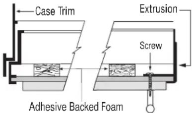
text_image
Case Trim Extrusion Screw Adhesive Backed FoamThis kit provides for the installation of Stainless Steel custom handles on 3/4" thick decorator door panels. The door extrusions allow these custom handles to be secured to the door structure, rather than to the custom panels. This kit contains all the necessary parts for dispenser and non-dispenser models.
This kit must be used in combination with ZKT36, ZKT42 or ZKT48 trim kit.
The ZKT trim kits provide the framework to support 3/4" thick panels. This kit provides handle side extrusions and handles to match that ZKT framework.
Note: It is best that 2 people install this kit.
Tools and materials required:
• #2 Phillips screwdriver
- Drill and 1/8", 9/32" bits
- Custom door panels
- Safety glasses
- Center punch
- Masking tape
- Hammer
- Pencil
- 1/2" thick 12" x 12" min. piece of plywood to protect floor when drilling
- For stainless steel panels wear gloves to protect against sharp edges.
Parts List:
A. Fresh food door extrusion
B. Freezer door extrusion
C.2 Stainless tubular handles
D. 8 Handle standoffs
E. 10 Screws for mounting handle
standoffs
(8 required, 2 extra)
F. 10 Set screws (8 required, 2 extra)
G. 3/32" Allen wrench for set screws
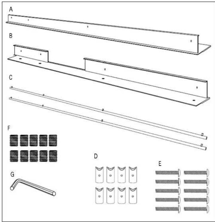
text_image
A B C F G D EBefore You Begin
- 3/4" custom panels must be routed to accommodate these handle extrusions. Rout the panels as illustrated, 1/4" deep, and 1-13/16" wide, top to bottom on the handle side.
- Follow the instructions in the ZKT trim kit to install support brackets to the bottom of the fresh food and freezer panels. For models with full width dispenser trim, install the support bracket to the bottom of the lower panel only. Do not install a bracket to the top of the lower panel or the bottom of the upper panel as shown in the ZKT trim kit instructions. These brackets are not required for this kit.
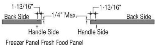
text_image
1-13/16" Back Side 1/4" Max. Handle Side 1-13/16" Handle Side Back Side Freezer Panel Fresh Food Panel
flowchart
graph TD
    A["Support Bracket"] --> B["Freezer Panel"]
    C["Back Side Door Panel"] --> D["Support Bracket"]
    E["Hinge Side"] --> F["Back Side Door Panel"]
    G["Bottom Edge"] --> H["Freezer Panel"]
    I["Bottom Edge"] --> J["Fresh Food Panel"]
Install bottom support brackets only.
Step 1: Remove Handles
- Open doors to 90^ . Remove the screws from the full-length handles of both doors.
- Retain screws, discard handles.
Note: If a custom collar is to be used, order ZWCD1 Trim Kit for 36" and 42" wide models. Order ZWCD2 for 48" wide models.
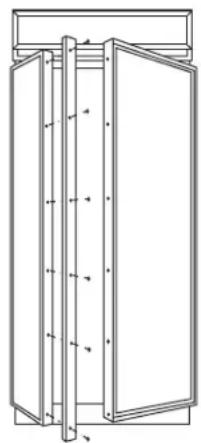
natural_image
Technical line drawing of a cabinet or enclosure with vertical supports and doorways (no text or symbols)Step 2: Match Handle Extrusions to Panels
- Cut a piece of corrugated to use as a pad to protect the panel finish. Use 1/2" thick section of plywood to protect flooring when drilling.
- Place custom panels on the pad, appearance side down.
Note: If panels are wood, be sure to note which end is the top so that wood grain is in the correct direction on both (or all 3) panels.
- Place new extrusion against the handle side of the panels.
- Align the extrusion evenly with the top and bottom of the panel.
- Follow the same procedure on the opposite panel.
- Tape the extrusions to the panels to prevent movement.
- Center punch and drill 1/8" pilot holes through the holes in the extrusion and into the panel.
- Turn panel over. On the appearance side, use 9/32" bit to enlarge clearance hole.
IMPORTANT: Hole locations must be exact to accept handle standoff and handle assembly.
For models with full width dispenser trim and 2 piece freezer panels:
- Carefully, align the top of the upper panel and the bottom of the lower panel with extrusion ends.

text_image
Top EndNote: Be sure to orient extrusions and handles correctly. The top ends of the extrusions are cutout to fit the shape of the top of the door.
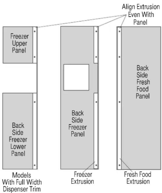
text_image
Freezer Upper Panel Back Side Freezer Lower Panel Models With Full Width Dispenser Trim Back Side Freezer Panel Freezer Extrusion Align Extrusion Even With Panel Back Side Fresh Food Panel Fresh Food ExtrusionTubular Stainless Steel Handles
Step 3: Install Standoffs onto Handles
- Place a handle standoff on each attachment post along the handle. Position the screw hole on the standoff to point to the floor.
• Install set screws into the bottom of each standoff, using the Allen wrench provided. The standoff should be tight against the handle.

text_image
Screw Allen WrenchStep 4: Install Handles
- Start mounting screws through the extrusion and just through the custom panel.
- Stand panels up on the hinge side and hold to access the appearance side. Place handle against mounting screws on the appearance side, drive top screw from the back of the extrusion partially into the standoff.
- Going down the handle, drive each screw partially into the standoff, alternating back to the top until the handle is tight against the door.
- Remove tape.
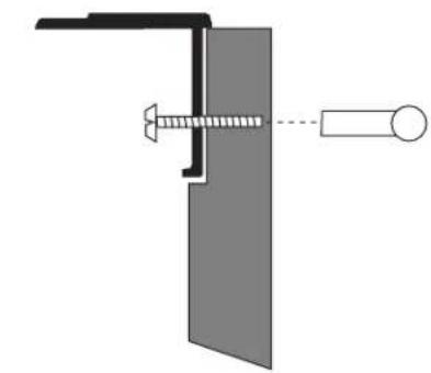
natural_image
Pure mechanical diagram showing a bracket and screw assembly without any text or symbols
text_image
ScrewStep 5: Install Assembled Panels
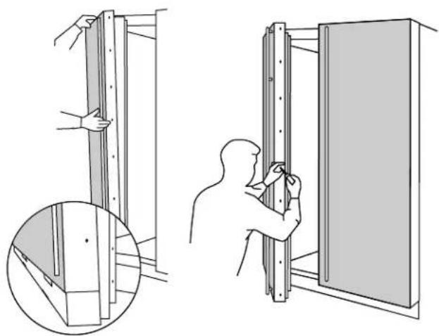
natural_image
Technical illustration showing two steps of installing or adjusting a wall-mounted panel, with magnified detail (no text or symbols)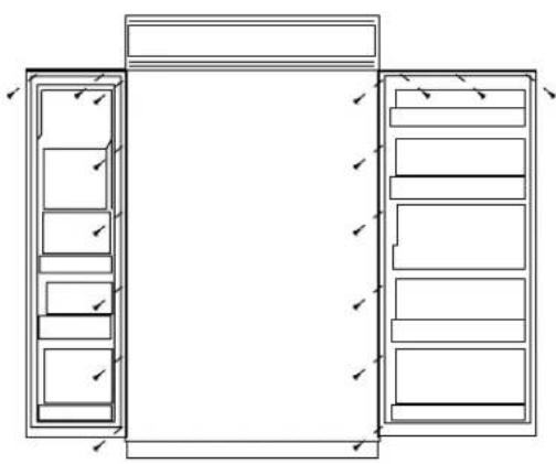
natural_image
Architectural line drawing of a two-story cabinet with drawers and doors, no text or symbols presentIt is best that 2 people perform this step.
- Place panel/handle assembly onto the bottom trim with support bracket tabs inserted into slots.
- Push and hold the panel back against the steel door with door handle extrusion flush to the handle side of the door.
- Reinstall original screws into the door extrusion.
- Open the door fully to stop.
• Install screws at the top, and hinge side.
- Follow the same procedure on the opposite door.
Step 5
Install
Assembled
Panels
(continued)
For models with full width dispenser trim and 2 piece freezer panels:
It is best that 2 people perform this step.
- Carefully, lift the assembled panel to the case trim. Hold both panels so they do not twist the extrusion.
- Insert the support bracket tabs into the bottom trim.
- Push and hold the panel back against the steel door.
- Reinstall original screws into the door extrusion.
- Open the door fully to stop.
• Install screws at the top, and hinge side.

natural_image
Architectural floor plan showing room layouts and door placements (no text or labels)Tools and materials required:
• #2 Phillips screwdriver
- Drill and appropriate bits
- Custom door panels
- Safety glasses
Kit contents
Parts List:
A. Collar trim
(Both black and white trim included)
B. Top bracket
C. Bottom bracket
D. Screws (2)
This kit provides for the use of a custom dispenser collar trim, replacing the standard full-width trim. This kit can be used alone, or combined with one or all other trim kits.

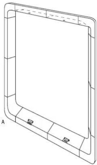
natural_image
Technical line drawing of a rectangular frame with corner brackets and a central blank space (no text or symbols)Select panel size
1/4" Thick Custom Panels
3/4" Thick Custom Panels with Standard Handles
3/4" Thick Custom Panels with Custom Handles
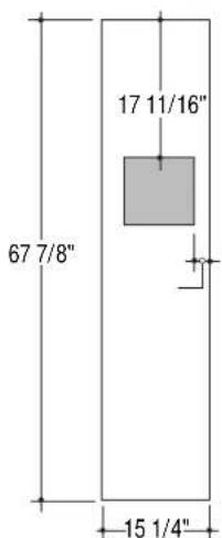
text_image
67 7/8" 17 11/16" 15 1/4"
text_image
67 15/16" 17 11/16" 2 5/16" 15 1/16"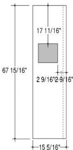
text_image
67 15/16" 17 11/16" 2 9/16"2 9/16" 15 5/16"The overall size of the panel is determined by the application being used.
- 1/4" thick panels using the standard handles or optional custom handles.
- 3/4" thick panels using standard handles, or
- 3/4" thick panels using optional custom handles. Select the panel size accordingly.
Cut dispenser hole and rout door panel
The use of this custom collar trim requires that the hole for dispenser be located and cut very accurately. 3/4" door panels must be routed on all 4 sides of the dispenser cutout.
Rout the back side of the panel 1/4" deep and 7/8" wide, flush with the edge of the cutout.
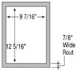
text_image
9 7/16" 12 5/16" 7/8" Wide RoutThe Cutout is 9 7/16" wide by 12 5/16" high. 3/4" panels must be routed on all four sides of the cutout. Rout the back side of the panel 1/4" deep. 7/8" wide.
Note: 1/4" door panels do not require routing.
Install collar brackets and trim

natural_image
Cross-sectional diagram of a mechanical component with internal channels and mounting features (no text or labels)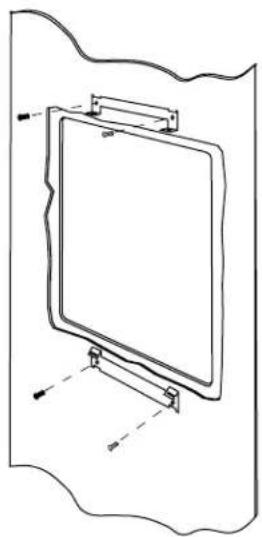
natural_image
Simple line drawing of a rectangular board mounted on a stand, with no text or symbols present.
natural_image
Technical line drawing of a rectangular frame with internal components and mounting holes (no text or symbols)Select the door panel size for your application.
- If using the standard 14 " trim, follow the installation instructions packed with the product.
- When using another optional trim kit, use the instructions provided with that kit to install the panel trim and/or custom handles.
- Remove the aluminum trim above and below the dispenser. Discard trim.
- Remove and discard the standard full-width dispenser trim.
-
Remove 2 screws above and below the dispenser recess. Retain screws.
-
Secure top and bottom brackets to the dispenser, using the screws previously removed.
• Install the custom panels according to the appropriate installation instructions. - Select the black or white collar trim according to appearance desired.
- Match the indentations on the collar trim to the tabs on the lower bracket. Push the collar flush against the door.
- Drive 2 screws (provided) upwards through the collar and into the brackets.
Note: While performing installations described in this book, safety glasses or goggles should be worn.
To obtain specific information concerning any Monogram product or service, call GE Answer Center® consumer information service at 800.626.2000-any time, day or night.
For Monogram™ local service in your area, call 1-800-444-1845.
Note: Product improvement is a continuing endeavor at General Electric. Therefore, materials, appearance and specifications are subject to change without notice.