H262-NO1 - Server GIGABYTE - Free user manual and instructions
Find the device manual for free H262-NO1 GIGABYTE in PDF.

User questions about H262-NO1 GIGABYTE
0 question about this device. Answer the ones you know or ask your own.
Ask a new question about this device
Download the instructions for your Server in PDF format for free! Find your manual H262-NO1 - GIGABYTE and take your electronic device back in hand. On this page are published all the documents necessary for the use of your device. H262-NO1 by GIGABYTE.
USER MANUAL H262-NO1 GIGABYTE
© 2023 Giga Computing Technology CO., LTD. All rights reserved.
The trademarks mentioned in this manual are legally registered to their respective owners.
Disclaimer
Information in this manual is protected by copyright laws and is the property of Giga Computing. Changes to the specifications and features in this manual may be made by Giga Computing without prior notice. No part of this manual may be reproduced, copied, translated, transmitted, or published in any form or by any means without Giga Computing's prior written permission.
Documentation Classifications
In order to assist in the use of this product, Giga Computing provides the following types of documentation:
■ User Manual: detailed information & steps about the installation, configuration and use of this product (e.g. motherboard, server barebones), covering hardware and BIOS.
■ User Guide: detailed information about the installation & use of an add-on hardware or software component (e.g. BMC firmware, rail-kit) compatible with this product.
■ Quick Installation Guide: a short guide with visual diagrams that you can reference easily for installation purposes of this product (e.g. motherboard, server barebones).
Please see the support section of the online product page to check the current availability of these documents.
For More Information
For related product specifications, the latest firmware and software, and other information please visit our website at http://www.gigabyte.com/Enterprise
For GIGABYTE distributors and resellers, additional sales & marketing materials are available from our reseller portal: http://reseller.b2b.gigabyte.com
For further technical assistance, please contact your GIGABYTE representative or visit https://esupport.gigabyte.com/ to create a new support ticket
For any general sales or marketing enquiries, you may also message GIGABYTE server directly by email: server.grp@gigabyte.com
Table of Contents
Chapter 1 Getting Started....5
1-1 Software Requirement 5
1-2 Gigabyte Management Console Network Configuration 6
1-3 Log In Gigabyte Management Console....7
1-3-1 Required Browser Settings: 8
1-4 Quick Button and Logged-in User 9
1-5 Help....10
1-6 Menu Bar....10
Chapter 2 Enter Gigabyte Management Console....11
2-1 Dashboard.... 11
2-2 Sensor....12
2-2-1 Sensor Detail....13
2-2-2 Sensor Events....14
2-3 System Inventory 15
2-3-1 CPU Inventory 15
2-3-2 DIMM Inventory 17
2-3-3 PCI Inventory....18
2-3-4 HDD Inventory....19
2-3-5 NIC Inventory....20
2-4 FRU Information....21
2-5 Logs & Reports 23
2-5-1 IPMI Event Log 23
2-5-2 System Log....24
2-5-3 Audit Log 25
2-5-4 Video Log 26
2-6 Settings 27
2-6-1 Captured BSOD....27
2-6-2 Date & Time....28
2-6-3 External User Services....29
2-6-4 KVM Mouse Settings....39
2-6-5 Log Settings....40
2-6-6 Manage Licenses 43
2-6-7 Media Redirection Settings....43
2-6-8 Network Settings 48
2-6-9 PAM Order Settings....56
2-6-10 Platform Event Filter....57
2-6-11 Services....65
2-6-12 SMTP Settings....69
2-6-13 SSL Settings....72
2-6-14 System Firewall 77
2-6-15 User Management....85
2-6-16 Video Recording....89
2-6-17 Fan Profile....97
2-6-18 Power Consumption 99
2-6-19 IMPI Interfaces ....100
2-6-20 RAID Management....101
2-7 Remote Control....112
2-8 Images Redirection 118
2-8-1 Remote Media 119
2-9 Power Control 120
2-10 Maintenance Group.... 121
2-10-1 Backup Configuration 122
2-10-2 Firmware Image Location....123
2-10-3 Firmware Information....124
2-10-4 Firmware Update....125
2-10-5 Preserve Configuration....130
2-10-6 Restore Configuration....134
2-10-7 Restore Factory Defaults....135
2-10-8 System Administrator....136
2-10-9 Sign Out....137
Chapter 1 Getting Started
1-1 Software Requirement
- Client machine with 8GB RAM.
- If the client machine has 4GB RAM, there will be lag in video/keyboard/mouse functionality.
Supported Browsers
- Chrome latest version.
- IE 11 and above.
- Firefox (with limited support).

Note: It is advisable to use Chrome or IE for H5Viewer since Firefox has its own memory limitations.
1-2 Gigabyte Management Console Network Configuration
Follow the instruction to enable the console redirection function.
- You can gather the IP address on the POST screen.

text_image
GIGABYTE™ BMC IP : 10.1.6.113 Press- Or, Go to BIOS setup menu.
- Select Server Management.
- Select BMC network Configuration.
- Define Configuration Address source to DynamicBmcDhcp or Static.
- Save and Exit.
- The BMC IP Address will appear on the Station IP address parameter.
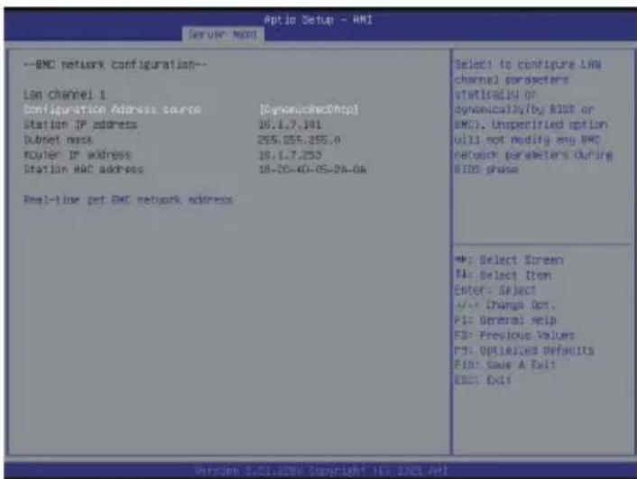
text_image
Optio Setup - ANI Server Mount --BNC network configuration-- LAN channel 1 Configuration Address source [Dynomus@http] Station IP address 10.1.7.191 Subnet mask 255.255.255.0 Router IP address 10.1.7.253 Station MAC address 18-05-40-05-24-06 Real-time get BNC network address Select to configure LAN channel parameters statically or dynomusaly(by BID or BMC). Unspecified option will not modify any BNC network parameters during BIOS phase +: Select Screen PA: Select Item Enter: Select +/- Change Opt. PI: General Help FD: Previous Values P5: Options/Default P10: Save A Fail EWS: Exit- Save the configuration and exit BIOS setup menu.
1-3 Log In Gigabyte Management Console
To access the Gigabyte Management Console, the MegaRAC utility will prompt you to enter the User Name and Password.

text_image
MEGARAC SP-X Username Password US - English Remember Username Sign me inI forgot my password
The fields are explained as follows:
For basic login to the MegaRAC UI, use the following login:
- Username: admin
- Password: Refer to unique MB serial number.
• US - English: Changes the interface language.

NOTE!
If your motherboard / server version is older than G9 (upgrade version), then use the following login:
Username: admin
Password: password
This serial number can be found on the serial number sticker located on the motherboard of every GIGABYTE server motherboard and system. The unique pre-programmed password will be the last 11 characters of the serial number. For example, for the below serial number, the password will be "JG4P6400027

text_image
1/A/JG4P64 00027GIGABYTE will also affix new stickers that display the unique BMC password (example below) to both the product box (packaging) and to the CPU cover (for motherboards sold separately) or the server chassis.

text_image
Unique BMC Password JG4P6400027Please see the reference guide below / attached for where to find locations of this sticker according to product / model type.
Products that have been implemented with this change will be indicated as version G9 on the "Upgrade Version" sticker located on the motherboard / motherboard anti-static packaging / server chassis / server packaging.

text_image
UPG VER: G□1 G□2 G□3 G□4 G□5 G□6 G□7 G□8 G□9 G□10+Remember Username: Check this option to remember your login credentials.
Sign me in: After entering the required credentials, click the Sign me in to login to GUI.
I forgot my password: If you forget your password, you can generate a new one using this link. Enter the user name, click on Forgot Password link. This will send the newly generated password to the configured Email-ID for the user.
1-3-1 Required Browser Settings:
Allow file download from this site: For Internet Explorer, Choose Tools ->Internet Options ->Security Tab, based on device setup, select among Internet, Local intranet, trusted sites and restricted sites. Click Custom level.... In the Security Settings - Zone dialog opened, under settings, find Downloads option, Enable File download option. Click OK to the entire dialog boxes.
For all Other Browsers, accept file download when prompted.
Enable javascript for this site: The icon indicates whether the javascript setting is enabled in browser.
Enable cookies for this site: The icon indicates whether the cookies setting are enabled in browser.

Cookies must be enabled in order to access the website.
1-4 Quick Button and Logged-in User
The user information and quick buttons are located at the top right of the Web GUI. A screenshot of the logged-in user information is shown below.

text_image
US - English Sync Refresh adminUser Information
The logged-in user information shows the logged-in user, his/her privilege and the four quick buttons allowing you to perform the following functions:
Logged-in user and its privilege level
This option shows the logged-in user name and privilege. There are five kinds of privileges.
User: Only valid commands are allowed.
Operator: All BMC commands are allowed except for the configuration commands that can change the behavior of the out-of-hand interfaces.
Administrator: All BMC commands are allowed.
No Access: Login access denied.
OEM: All OEM commands are allowed.
Refresh: Click the icon to reload the current page.
Sync: Click the icon to synchronize with Latest Sensor and Event Log updates.
US - English: Click to select the language of the Web GUI.
Warning: Click to view the warning messages.
Notification: Click the icon to view the notification messages.
1-5 Help
Help - The Help icon (?) is Located at the top right of the each page in Web GUI. Click this help icon to view more detailed field descriptions.
1-6 Menu Bar
The menu bar displays the following:
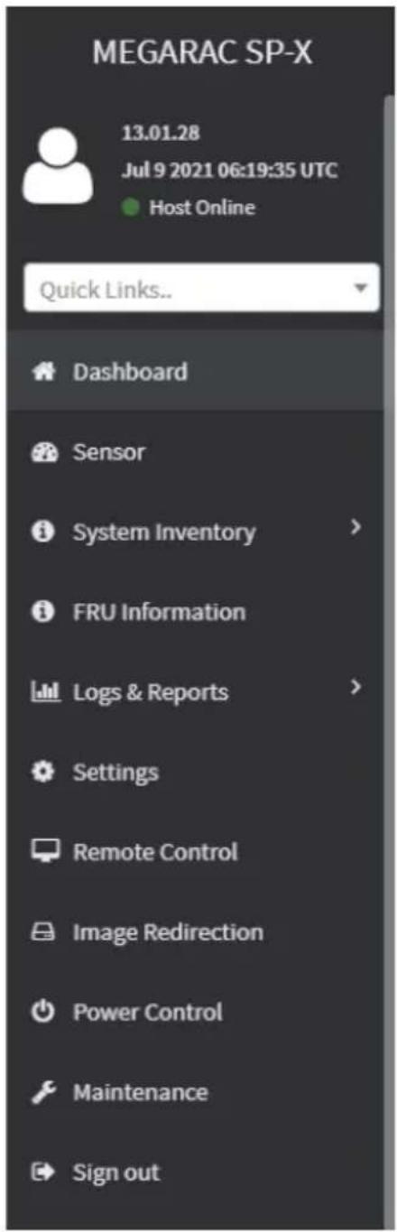
text_image
MEGARAC SP-X 13.01.28 Jul 9 2021 06:19:35 UTC Host Online Quick Links.. Dashboard Sensor System Inventory > FRU Information Logs & Reports > Settings Remote Control Image Redirection Power Control Maintenance Sign outChapter 2 Enter Gigabyte Management Console
2-1 Dashboard
The Dashboard page gives the overall information about the status of a device.
To open the Dashboard page, click Dashboard from the menu bar. It displays the following:
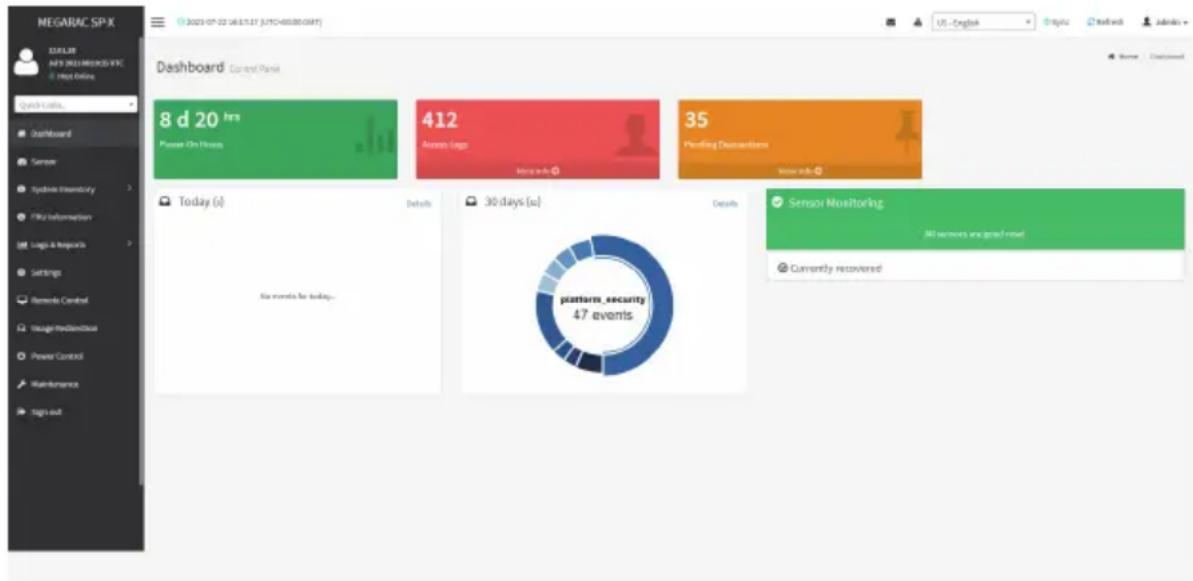
text_image
MEGARAC SP-X 12:55:38 MAY 2021 MEGARAC SP-X Hot Online Quick Loans... Dashboard Control Panel 8 d 20 hrs Please On Hours 412 Access Links 35 Pricing Dispositions Today (s) Details 30 days (s) Details Six events for today. platform_security 47 events Sensor Monitoring All learners are good news. Currently recoveredDashboard
A brief description of the Dashboard page is given below.
Power-On Hours
It indicates the power-on time.
Pending Deassertions
It lists the all pending events incurred by various sensors and occupied/available space in logs can be viewed. To know about the pending events details, click the More info link. This navigates to the Event Log page.
Access Logs
A graphical representation of all events incurred by various sensors and occupied/available space in logs can be viewed, if you click on the More info link, you can view the Audit Log page.
Today & 30 Days (Event Logs)
This page displays the list of event logs occurred by the different sensors on this device. Click Details link on Today and 30 days to view the event logs for Today and 30 days respectively.
Sensor Monitoring
It lists all the critical sensors on the device. If you click on any list sensor, you can view the Sensor detail page with the Sensor information and Sensor Events details.
2-2 Sensor
The Sensor Readings page displays all the sensor related information.
To open the Sensor Readings page, click Sensor from the menu. Click on any sensor to show more information about that particular sensor, including thresholds and a graphical representation of all associated events.
A sample screenshot of Sensor Readings page is shown below.
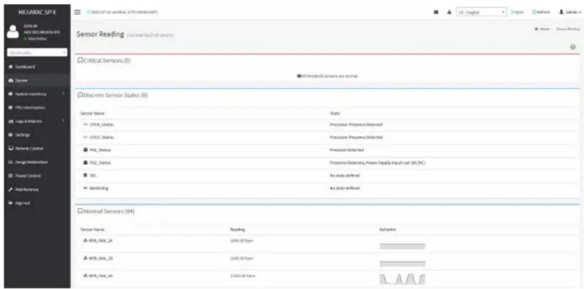
text_image
MEGARIC SP-X SUSIL NEW INJEMERSON &C New Online Quick Links... Dashboard Sensor Analysis inventory File information Logic & Impacts Settings Network Control Image/Redirections Power Control Maintenance Big set Sensor Reading: User reading all sensors Critical Sensors (0) All threshold sensors are normal Discrete Sensor States (6) Sensor Name State CPU Status Processor Preference Detected CPU Status Processor Preference Detected PSL Status Processor Detected PSL Status Processor Detected, Power Supply Input Load (A1/B2) SEL No state defined Wurstaking No state defined Normal Sensors (04) Sensor Name Reading Behavior BPS/NAR_3A 2000.00 fps BPS/NAR_3B 2400.00 fps BPS/NAR_3A 12000.00 fpsThe Sensor Readings page contains the following information:
In this Sensor Reading page, Live readings for all the available sensors with details like Sensor Name, Status, Current Reading and Behavior will be appeared, else you can choose the sensor type that you want to display from the list. Some examples for sensors are Temperature Sensors, Fan Sensors, Watchdog Sensors and Voltage Sensors etc.
Note: Four DIMM Temp sensors are deployed for monitoring the DIMM temperature on the system. Users must take notice that the live reading of each DIMM Temp sensor indicates the temperature of a DIMM group, not the temperature of a specific DIMM.

Note: Four DIMM Temp sensors are deployed for monitoring the DIMM temperature on system. Users must take notice that the live reading of each DIMM Temp sensor indicates the temperature of a DIMM group, not the temperature of a specific DIMM.
2-2-1 Sensor Detail
Select a particular sensor from the Critical Sensor or Normal Sensor lists. The Sensor Information as Live Widget and Thresholds for the selected sensor will be displayed as shown below.

Note: For Illustrative Purpose, a sample screenshot of Sensor detail page with Change thresholds option is shown and explained below.
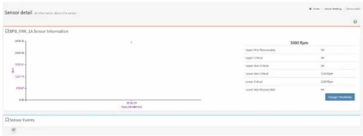
line
| Metric | Value | | --- | --- | | Upper Non-Responsibility | NA | | Upper Critical | NA | | Upper Non-Critical | NA | | Lower Non-Critical | 1540 Rpm | | Lower Critical | 1230 Rpm | | Lower Non-Product | NA | | Time Period | 0:30 - 29:30 |
Note: Widgets are little gadgets, which provide real time information about a particular sensor. User can track a sensor's behavior over a specific amount of time at specific intervals. The result will be displayed as a line graph in the widget. The session will not expire, until the widgets gets a live data of the last widget that is kept opened.
For the selected sensor, this widget gives a dynamic representation of the readings for the sensor.
There are six types of thresholds:
• Lower Non-Recoverable (LNR)
- Lower Critical (LC)
• Lower Non-Critical (LNC)
• Upper Non-Recoverable (UNR)
• Upper Critical (UC)
• Upper Non-Critical (UNC)
The threshold states could be Lower Non-critical - going low, Lower Non-critical - going high, Lower Critical - going low, Lower Critical - going high, Lower Non-recoverable - going low, Lower Non-recoverable - going high, Upper Non-critical - going low, Upper Non-critical - going high, Upper Critical - going low, Upper Critical - going high, Upper Non-recoverable - going low, Upper Non-recoverable - going high.
A graphical view of these events (Number of Entries vs. Thresholds) can be viewed as shown in the Sensor Readings page screenshot.
2-2-2 Sensor Events
The Sensor Events page displays information about events that have triggered the system's sensor. A sample screenshot of Sensor Events page is shown below.
| Sensor Events | |
| unlaided use | |
| ID: 60 unknown sensor of type platform_security logged a bias: oem timestamped was discounted | 16 days ago |
| ID: 79 unknown sensor of type platform_security logged a bias: oem timestamped was discounted | 2 days ago |
| ID: 74 unknown sensor of type platform_security logged a bias: oem timestamped was discounted | 3 days ago |
| ID: 71 unknown sensor of type platform_security logged a bias: oem timestamped was discounted | 4 days ago |
| ID: 76 unknown sensor of type platform_security logged a bias: oem timestamped was discounted | 5 days ago |
| ID: 54 unknown sensor of type platform_security logged a bias: oem timestamped was discounted | 6 days ago |
| ID: 73 unknown sensor of type platform_security logged a bias: oem timestamped was discounted | 7 days ago |
| ID: 72 unknown sensor of type platform_security logged a bias: oem timestamped was discounted | 8 days ago |
| ID: 71 unknown sensor of type platform_security logged a bias: oem timestamped was discounted | 9 days ago |
| ID: 23 HDMI sensor of type drive Island logged a EPB Virtual Management Controller Event: Drive Presence was answered | 10 days ago |
| ID: 18 HDMI sensor of type drive Island logged a EPB Virtual Management Controller Event: Drive Presence was answered | 11 days ago |
2-3 System Inventory
The System Inventory page displays the following information:
- CPU Inventory
- DIMM Inventory
- PCI Inventory
- HDD Inventory
- NIC Inventory
A screenshot displaying the menu items under System Inventory is shown below.

text_image
System Inventory » CPU Inventory » DIMM Inventory » PCI Inventory » HDD Inventory » NIC InventoryA detailed description of System Inventory is given below.
2-3-1 CPU Inventory
This page displays all detected CPUs on this device. Select one CPU to see the details of that entry or click on Expand All to view all entries in details. Click Download SMBIOS file to download the SMBIOS file.

text_image
NEGARAC SP-X 11/01/28 API: 2023.10.28 (EVI) - 3476-0000000001 CPU Inventory + CPU: 1bit(87) item(R) $/km 425/CPU @ 2.16GHz + CPU: 1bit(87) item(R) $/km 425/CPU @ 2.16GHz Categories of Cycles/Hz Current Demand/Hours Resource Research Data(D) Resource Resource Selection
text_image
MEGARAC SPX MAGULAR AVI PROGRESSIVE - Fixed Data CPU Inventory Cognar III Exported Forward IndicAta CPU: Info(PCI) Name(R) Silver 430 CPU @ 1.0GHz Detail information for CPU Manufacturer Family Extraint Clock Max Speed Speed Eval-Board Eval-Enabled Trivac/CovarF MAGRRC Corporation Room 338,000 MHz 5,300 GHz 2,000 MHz 11 12 24 Capability Information for CPU CPU Capability Area Expedia Enabled Virtual Machine Settings (INT) 6 HyperThreading[NT] 6 Inverter Disaster (AD) 6 Turbo Mode 6 Cache Information for CPU Level Maintenance Size Installed Size Type Write Back Policy Real Connection Type 1 398 398 Unified Write Back Single bit ESC 2 13960 13960 Unified Varies With Memory Address Single bit ESC 3 18452 18452 Unified Varies With Memory Address Single bit ESC + CPU: Info(PCI) Name(R) Silver 430 CPU @ 1.0GHz2-3-2 DIMM Inventory
This page displays all detected DIMMs on this device. It allows you to see memory attributes, individual memory details or all entries in detail by clicking on Expand All. Click Download SMBIOS file to download the SMBIOS file.
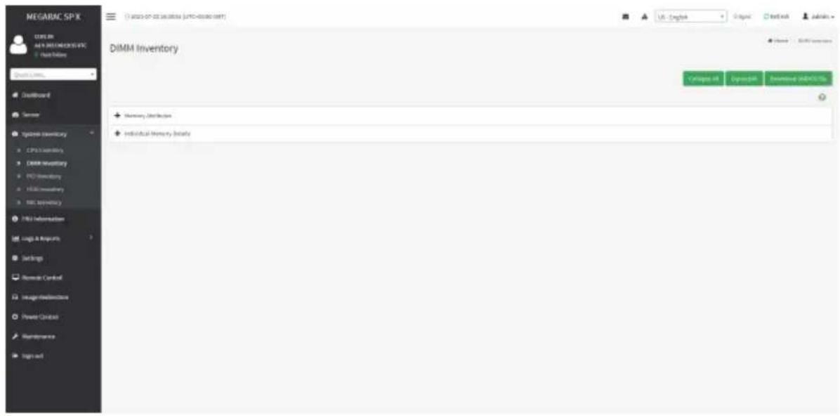
text_image
MEGARAC SP.K CUBE IN AN IN DIMEA/REVENUE Quick Online Quick Links... Dashboard Server system inventory CPU inventory DXMM inventory PCI inventory HDMI inventory MAC inventory FMS information Log1 & Reports Settings Remote Control Image/Redistribution Power Control Maintenance Sign out DiMM Inventory + Memory Distribution + individual Memory Details sell-in: 0000000000000000000000000000000000000000000000000000000000000000000000000000000000000000000000000000 sell-in: 18,426,365,985 (LPTD-455388) 18,426,365,985 (LPTD-455388) 18,426,365,985 (LPTD-455388) 18,426,365,985 (LPTD-455388) 18,426,365,985 (LPTO-455388) 18,426,365,985 (LPTO-455388) 18,426,365,985 (LPTO-455388) 18,426,365,985 (LPTO-455388) 18,426,366,985 (LPTO-455388) 18,426,366,985 (LPTO-455388) 18,426,366,985 (LPTO-455388) 18,426,366,985 (LPTO-455388) 17,426,366,985 (LPTO-455388) 17,426,366,985 (LPTO-455388) 17,426,366,985 (LPTO-455388) 17,426,366,985 (LPTO-471111) sell-in: 18,426,366,985 (LPTO-471111) sell-in: 18,426,366,985 (LPTO-471111) sell-in: 18,426,366,985 (LPTO-471111) sell-in: 18,426,366,177 (LPTO-471111) sell-in: 18,426,366,985 (LPTO-471111) sell-in: 18,426,366,985 (LPTO-471111) sell-in: 18,426,366,985 (LPTO-471127) sell-in: 18,426,366,985 (LPTO-471127) sell-in: 18,426,366,985 (LPTO-471127) sell-in: 18,426,366,985 (LPTO-471127) sell-in: 18,432,366,985 (LPTO-471127) sell-in: 18,432,366,985 (LPTO-471127) sell-in: 18,432,366,985 (LPTO-471127) sell-in: 18,432,366,985 (U.S.-English) sell-in: 18,432,366,985 (U.S.-English) sell-in: 18,432,366,985 (U.S.-English) sell-in: 18,432,366,985 (U.S.-English) sell-in: 18,432,366,985 (U.S.-English) sell-in: buy in the financial account. buy in the financial account. buy in the financial account. buy in the financial account. buy in the financial account. buy in the financial account. buy in the financial account. buy in the financial account. buy in the financial account. buy in the financial account. buy in the financial account. buy in the financial account. buy in the financial account. buy in the financial account. buy in the financial account. buy in the financial account. buy in the financial account. buy in the Financial account. buy in the Financial account. buy in the Financial account. buy in the Financial account. buy in the Financial account. buy in the Financial account. buy in the Financial account. buy in the Financial account. buy in the Financial account. buy in the Financial account. buy in the Financial account. buy in the Financial account. buy in the Financial account. buy in the Financial account. buy in the Financial account. buy in the Financial account. buy in the Financial account. buyin an additional report.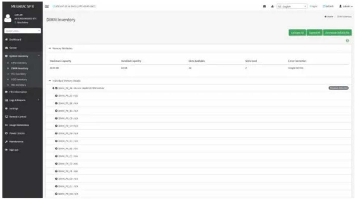
text_image
NEGARAC SP-X COULIN KEY INJEMERATE File Before Quick Links Default Sensor System Inventory CPU2 inventory DMM inventory PEG inventory TDD inventory MCC inventory FBS Information Log & Improve Settings Remote Control Image Monitoring Power Control Maintenance Sign out DiMM Inventory Capacity Installed Capacity Slots Available Slots Used Error Connection 00:00 GB 1st GB 3D 2 Single-set ETC. Individual Memory Assets ● 2004A_PP_A8 : Include QUADRATSPD AC/AN ● 2004A_PP_B2 : N/A ● 2004A_PP_B6 : N/A ● 2004A_PP_B7 : N/A ● 2004A_PP_C3 : N/A ● 2004A_PP_C11 : N/A ● 2004A_PP_D01 : N/A ● 2004A_PP_D3 : N/A ● 2004A_PP_E1 : N/A ● 2004A_PP_E2 : N/A ● 2004A_PP_E3 : N/A ● 2004A_PP_E4 : N/A ● 2004A_PP_E5 : N/A ● 2004A_PP_E6 : N/A ● 2004A_PP_E7 : N/A2-3-3 PCI Inventory
This page displays all detected PCI cards on this device. It allows you to see on-board PCI cards, add-on PCI cards or all entries in detail by clicking on Expand All. Click Download SMBIOS file to download the SMBIOS file.

text_image
MEGARAC SP.K CENSER AEN MEGARAC SP.K Data Table Quan CNTK Disikboard Server System inventory CPG System Link inventory PCI inventory FRC inventory FRC Inventory FRC Information Loga & Projects Settings Remote Control Image streamlines Power Control Maintenance Traps and PCI Inventory On Record USB - https://88880.0001/ Groups #1 Groups #2 Groups #3 Groups #4 Groups #5 Groups #6 Groups #7 Groups #8 Groups #9 Groups #10 Groups #11 Groups #12 Groups #13 Groups #14 Groups #15 Groups #16 Groups #17 Groups #18 Groups #19 Groups #20 Groups #21 Groups #22 Groups #23 Groups #24 Groups #25 Groups #26 Groups #27 Groups #28 Groups #29 Groups #30 Groups #31 Groups #32 Groups #33 Groups #34 Groups #35 Groups #36 Groups #37 Groups #38 Groups #39 Groups #40 Groups #41 Groups #42 Groups #43 Groups #44 Groups #45 Groups #46 Groups #47 Groups #48 Groups #49 Groups #50
text_image
NEGAPEC SPX CENSER AS/1000 ELECTRONIC PPO 1. Hold Date PCI Inventory De Board USB Catalyst Network Connection Manufacturer Type Version ID Device ID Link Width Link Speed Intel Corporation Internal controller InsUR InsUR InsUR InsUR InsUR InsUR InsUR InsUR InsUR InsUR InsUR InsUR InsUR InsUR InsUR InsUR InsUR InsUR InsUR InsUR InsUR InsUR InsUR InsUR InsUR InsUR InsUR InsUR InsUR InsUR InsUR InsUR InsUR InsUR InsUR InsUR InsUR InsUR InsUR InsUR InsUR InsUR InsUR InsUR InsUR InsUR InsUR InsUR InsUR InsUR Insur Intel Corporation Internal controller InsUR InsUR InsUR InsUR InsUR InsUR InsUR InsUR InsUR InsUR InsUR InsUR InsUR InsUR InsUR InsUR InsUR InsUR InsUR InsUR InsUR InsUR InsUR InsUR InsUR InsUR InsUR InsUR InsUR InsUR InsUR InsUR InsUR InsUR InsUR InsUR InsUR InsUR InsUR InsUR InsUR InsUR InsUR InsUR InsUR InsUR InsUR Instr Manufacturer Type Version ID Device ID Link Width Link Speed Intel Corporation Internal controller InsUR InsUR InsUR InsUR InsUR InsUR InsUR InsUR InsUR InsUR InsUR InsUR InsUR InsUR InsUR InsUR InsUR InsUR InsUR InsUR InsUR InsUR InsUR InsUR InsUR InsUR InsUR InsUR InsUR InsUR Instr Intel Corporation Internal controller Instrus Instrus Instrus Instrus Instrus Instrus Instrus Instrus Instrus Instrus Instrus Instrus Instrus Instrus Instrus Instrus Instrus Instrus Instrus Instrus Instrus Instrus Instrus Instrus Instrus Instrus Instrus Instrus Instrus Instrus Instrus Instrus Instrus Instrus ICSI AS/1000 Catalyst Family Manufacturer Type Version ID Device ID Link Width Link Speed AS/1000 Technologies, Inc. VGA compatible controller In-2483 In-2000 In-2000 Gen 5 AS/1000 PC-MSP PD design Manufacturer Type Version ID Device ID Link Width Link Speed AS/1000 Technologies, Inc. PCI bridge In-1963 In-1530 X1 Gen 52-3-4 HDD Inventory
This page displays all detected HDDs on this device. It allows you to see on-board HDDs, add-on HDDs or all entries in detail by clicking on Expand All. Click Download SMBIOS file to download the SMBIOS file.

text_image
NEGARAC SP-X STELDR AI & BOSI SPROVING PPO + Free Online Quick URL: Outboard Sense Options Inventory CPX Inventory EBOX Inventory FCD Inventory HDD Inventory Net Inventory My Information UM Logs & Reports Settings Remote Control Images Preferences Power Controls Maintenance Sign and 2023-07-22 18:25:42 (UFC-40000.001) HDD Inventory + On Board UK - English Japan Hong Kong China HSC Summary En Figure 44 Open 44 Overputable Outlook 6x
text_image
MEGARC SP-X MELDR AFS 2021/08/20/2021 + Real Value Chard value... Outboard Server System Inventory CPU Inventory DARK Inventory FCS Inventory HDI Inventory PSC Inventory FBS Information Logic & Projects Settings Remote Control Image Initialization Power Control Maintenance Sign out HDD Inventory Cn Booked PCN data0 + installable data1 + installable data2 data3 data4 data5 data6 data7 data8 data9 data10 data11 data12 data13 data14 data15 data16 data17 data18 data19 data20 data21 data22 data23 data24 data25 data26 data27 data28 data29 data30 data31 data32 data33 data34 data35 data36 data37 data38 data39 Data - English Origin: http://www.megarc SP-X/ Database: http://www.megarc SP-X/ Name: HDD inventory2-3-5 NIC Inventory
This page displays all detected NICs on this device. It allows you to on-board NICs, add-on NICs or all entries in detail by clicking on Expand All. Click Download SMBIOS file to download the SMBIOS file.

text_image
MEGARAC SP-X C:\BCL.BI A4.9\NEE1\MEDR305-FEC None before Quick Limit, Installboard Server system inventory CPU secondary EMBR inventory PCI inventory HEC inventory NIC inventory TBS information Logis & Shipouts Settings Remote Control Image dissemination Power Control Maintenance tripls out NIC Inventory + On Record US - English Organic Textbook Admins Name: In-Inventory Collapse All Cyprachtik Overview (HIND) No.
text_image
NEGARAC SP-X CBLER JAS 2013 NOGARAC SPX NICE Online Quick Lines... Cashboard Sensor system inventory CPU transically LIMR inventory FCD inventory HFD inventory NIC Inventory PBS information Logis & requests Settings Reprode Control Image stream/voice Power Control Maintenance trign out NIC Inventory On Board USB-Cognitive Network Connection PortB MAC - ab-farm(069p.m07) Port1 MAC - 25.5m-02.08(a3.02) Categus.it Egracitek Download (SABOCOS)2-4 FRU Information
FRU Information page displays the BMC's FRU device information. FRU page shows information like Basic Information, Chassis Information, Board Information and Product Information of the FRU device.
To open the FRU Information page, click FRU Information from the menu bar. Select a FRU Device ID from the FRU Information section to view the details of the selected device. A screenshot of FRU Information page is shown below.

text_image
NEGARAC SP-X 2021-07-28 16:28:22 [JYF0400001589T] FRU Yield Preplicable Units Available FRU Devices FRU Device ID: FRU Device Name: BAC_FRU Chassis Information Chassis Information Area Format Version 1 Chassis Type Rack Mount Chassis Chassis Part Number 03324667 Chassis Serial Number 033246678601234597656A8 Chassis Extra Board Information Board Information Area Format Version 1 Language 0 Manufacture Date Time Fri Jan 19/03/2021 Board Manufacturer GSABYTE Board Product Name ABEQ-F51-08 Board Serial Number UZSP1288825 Board Part Number 129436785A8 FRU File ID Board EAuto NULL Product information Product information Area Format Version 1 Language 0 Product Manufacturer GSABYTE Product Name RSQ-HA2-00 Product Part number 08800860001 Product Nensor QUS Product Serial Number SLHPPE32P0E33 Rout Tag OS316M YB80 L23056788A8 FRU File ID PlaceD1#GUAThe following fields are displayed here for the selected device:
Available FRU Devices
- FRU device ID - Select the device ID from the drop down list
- FRU Device Name - The device name of the selected FRU device.
Chassis Information
- Chassis Information Area Format Version
- Chassis Type
- Chassis Part Number
- Chassis Serial Number
- Chassis Extra
Board Information
• Board Information Area Format Version
- Language
• Manufacture Date Time
- Board Manufacturer
- Board Product Name
- Board Serial Number
- Board Part Number
- FRU File ID
- Board Extra
Product Information
• Product Information Area Format Version
- Language
• Product Manufacturer
- Product Name
• Product Part Number
- Product Version
• Product Serial Number
- Asset Tag
- FRU File ID
- Product Extra
2-5 Logs & Reports
The Logs & Reports page displays the following information:
- IPMI Event Log
- System Log
- Audit Log
- Video Log
A screenshot displaying the menu items under Logs & Reports is shown below.

text_image
Logs & Reports » IPMI Event Log » System Log » Audit Log » Video LogA detailed description of Logs & Reports is given below.
2-5-1 IPMI Event Log
This page displays the list of event logs occurred by the different sensors on this device. Double click on a record to see the details of that entry. You can use the sensor type or sensor name filter options to view those specific events or you can also sort the list of entries by clicking on any of the column headers.
To open the Event Log page, click Logs & Reports > IPMI Event Log from the menu bar. A sample screenshot of Event Log page is shown below.

text_image
MEGARC SP-X 11.01.30 MAY 2021 MEGARC SP-X - New Online Event Log All events were logged Filter by Date: 2019-01-01 00:00 2021-07-22 18:47 Filter by type: all events All events Page 1 Show the event log Show the event log Event Log: 83 (5 - 30) July 2021 (1) 82 unknown sensor of type platform_security logged a title: own timestamped was deasserted (2) 83 unknown sensor of type platform_security logged a title: own timestamped was deasserted (3) 84 unknown sensor of type platform_security logged a title: own timestamped was deasserted (4) 85 unknown sensor of type platform_security logged a title: own timestamped was deasserted (5) 86 unknown sensor of type platform_security logged a title: own timestamped was deasserted (6) 87 unknown sensor of type platform_security logged a title: own timestamped was deasserted Event Logs StatisticsThe Event Log page consists of the following fields:
Filter By Date: Filtering can be done by selecting Start Date and End Date.
Filter By Type: The category could be either All Events, System Event Records, OEM Event Records, BIOS Generated Events, SMI Handler Events, System Management Software Events, System Software - OEM Events, Remote Console software Events, Terminal Mode Remote Console software Events.

Note: Once the Filter By Date and Filter type are selected, the list of events will displayed with the Event ID, Time Stamp, Sensor Type, Sensor Name and Description.
Event Log Statistics: Displays the statistical graph for the selected date.
Clear Event Logs: Deletes all the event logs.
Download Event Logs: Downloads the event logs.
Procedure
- From the Filter By Date field, select the time period by Start Date and End Date using Calendar for the event categories.
- From the Filter By Type field, select the Type of the event and Sensor name to view the events for the date. The events will be displayed based on the selected time period.
- To clear all events from the list, click Clear All Event Logs.
- To download the event logs, click Download Event Logs.
2-5-2 System Log
To open the System Log page, click Logs & Reports > System Log from the menu bar.
A sample screenshot of System Log page is shown below.
Note: Logs must be configured under Settings > Logs Settings > Advanced Log Settings to display any entries. Filtering options are also available for this and all logs in this section.

text_image
MEGARAC SP-X 12/01/28 MAY 2021.MEGARAC SP-X Start Online Quick Links... Dashboard Server Systems Inventory File Information Logic & Resources SPX-Brand Log Systems Log FitLog Video Log Settings Depside Control Usage Multimedia Power Control Maintenance Sign out System Log: Adjust system event logs Filter by Date: 2019-01-01 00:00 - 2021-07-22 16:48 Event Category: Alert Pages Event Log: (R - I) July 2021 ID: 1 2021-07-13 19:55:05 (UTC+08:00 GMT) JAHEDAEI006A305 kernel kernel--- [6.000354] Copyright IX: 2009-2013 American Regatirends Inc. -The System Log page consists of the following fields:
Filter By Date: Filtering can be done by selecting Start Date and End Date.
Event Category: Filters the events you want to track based on the type of event. Options include Alert, Critical, Error, Notification, Warning, Debug, Emergency, Information.
Download Logs: Allows you to download the system logs.
Procedure
- From the Filter By Date field, select the time period by Start Date and End Date using Calendar for the event categories.
- From the Event Category field, select the Category of the event to view the relevant events for the dates. The events will be displayed based on the selected time period.
- To download the event logs, click Download Logs.
2-5-3 Audit Log
To open the Audit Log page, click Logs & Reports > Audit Log from the menu bar. A sample screenshot of Video Log page is shown below.
Note: For configuration, go to Settings > Log Settings > Advanced Log Settings.
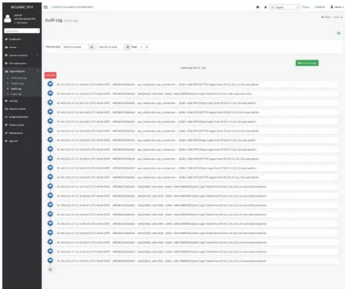
text_image
MEGARAC SPX AUDIT Log Filter by Date: 2015-01-25 20:00 EventLog: 4.0 (E - 28) ID: 431 3311-CP-22 28:00:07 (UTC+00:00 GMT) AM/DSX3D06A001 spx_retestservice.spx_retestservice -- [ID: 0290 HTTP] HTTPS logout from IP:203.74.122.101 useradmin- ID: 443 3311-CP-22 28:00:09 (UTC+00:00 GMT) AM/DSX3D06A001 sxtd[house] sxtd name - jassc - mava WARRANTY(sxtd Logis Failed from IP:203.74.122.101 useradmin- ID: 469 3311-CP-22 28:17:35 (UTC+00:00 GMT) AM/DSX3D06A001 spx_retestservice.spx_retestservice -- [ID: 0290 HTTP] https Legis from IP:203.74.122.183 useradmin- ID: 468 3311-CP-22 8x16:49 (UTC+00:00 GMT) AM/DSX3D06A001 spx_retestservice.spx_retestservice -- [ID: 0290 HTTP] HTTPS logout from IP:203.74.122.161 useradmin- ID: 467 3311-CP-22 8x16:49 (UTC+00:00 GMT) AM/DSX3D06A001 spx_retestservice.spx_retestservice -- [ID: 0290 HTTP] https Legis from IP:203.74.122.183 useradmin- ID: 466 3311-CP-22 8x16:58 (UTC+00:00 GMT) AM/DSX3D06A001 spx_retestservice.spx_retestservice -- [ID: 0290 HTTP] HTTPS logout from IP:203.74.122.165 useradmin- ID: 464 3311-CP-22 35:06:54 (UTC+00:00 GMT) AM/DSX3D06A001 spx_retestservice.spx_retestservice -- [ID: 0290 HTTP] https Legis from IP:203.74.122.183 useradmin- ID: 465 3311-CP-22 35:06:54 (UTC+00:00 GMT) AM/DSX3D06A001 spx_retestservice.spx_retestservice -- [ID: 0290 HTTP] https Legis from IP:203.74.122.183 useradmin- ID: 463 3311-CP-22 35:06:55 (UTC+00:00 GMT) AM/DSX3D06A001 spx_retestservice.spx_retestservice -- [ID: 0290 HTTP] HTTPS logout from IP:203.74.122.161 useradmin- ID: 462 3311-CP-22 35:16:55 (UTC+00:00 GMT) AM/DSX3D06A001 spx_retestservice.spx_retestservice -- [ID: 0290 HTTP] https Legis from IP:203.74.122.183 useradmin- ID: 461 3311-CP-22 35:02:59 (UTC+00:00 GMT) AM/DSX3D06A001 spx_retestservice.spx_retestservice -- [ID: 0290 HTTP] HTTPS logout from IP:203.74.122.165 useradmin- ID: 460 3311-CP-22 35:47:55 (UTC+00:00 GMT) AM/DSX3D06A001 sxtd[house] sxtd 4556 - [ID: 4364 WARRANTY(sxtd Logis Failed from IP:222.124.135.114 asstelece democratic- ID: 459 3311-CP-22 35:48:58 (UTC+00:00 GMT) AM/DSX3D06A001 sxtd[house] sxtd 5576 - [ID: 3978 WARRANTY(sxtd Logis Failed from IP:222.124.135.114 asstelece democratic- ID: 464 3311-CP-22 35:48:57 (UTC+00:00 GMT) AM/DSX3D06A001 sxtd[house] sxtd 5576 - [ID: 3978 WARRANTY(sxtd Logis Failed from IP:222.124.135.114 asstelece democratic- ID: 467 3311-CP-22 35:49:59 (UTC+00:00 GMT) AM/DSX3DowAtoz sxtd[house] sxtd zinsa - [ID: nava WARRANTY(sxtd Logis Failed from IP:222.124.135.114 asstelece democratic- ID: 466 3311-CP-22 35:49:58 (UTC+00:00 GMT) AM/DSX3DZGAOIO sxtd[house] sxtd 5546 - [ID: 3964 WARRANTY(sxtd Logis Failed from IP:222.124.135.114 asstelece democratic- ID: 465 3311-CP-22 35:49:57 (UTC+00:50 GMT) AM/DSX3DZGAOIO sxtd[house] sxtd 5546 - [ID: 3964 WARRANTY(sxtd Logis Failed from IP:222.124.135.114 asstelece democratic- ID: 464 3311-CP-22 35:49:56 (UTC+00:55 GMT) AM/DSX3DZGAOIO sxtd[house] sxtd 5546 - [ID: 3964 WARRANTY(sxtd Logis Failed from IP:222.124.135.114 asstelece democratic- ID: 463 3311-CP-22 35:49:55 (UTC+00:55 GMT) AM/DSX3DZGAOIO sxtd[house] sxtd 5546 - [ID: 3964 WARRANTY(sxtd Logis Failed from IP:222.124.135.114 asstelece democratic- ID: 462 3311-CP-22 35:49:54 (UTC+00:58 GMT) AM/DSX3DZGAOIO sxtd[house] sxtd 5546 - [ID: 3964 WARRANTY(sxtd Logis Failed from IP:222.124.135.114 asstelece democratic- ID: 461 3311-CP-22 35:49:53 (UTC+00:59 GMT) AM/DSX3DZGAOIO sxtd[house] sxtd 5546 - [ID: 3964 WARRANTY(sxtd Logis Failed from IP:222.124.135.114 asstelece democratic- ID: 46The Audit Log page consists of the following fields:
Filter By Date: Filtering can be done by selecting Start Date and End Date.
Download Logs: Allows you to download the audit logs.
Procedure
- From the Filter By Date field, select the time period by Start Date and End Date using Calendar for the event categories.
- To download the event logs, click Download Logs.
2-5-4 Video Log
To open the Video Log page, click Logs & Reports > Video Log from the menu bar.
A sample screenshot of Video Log page is shown below.
Note: Video Trigger Settings should be enabled, to display the Video Log page. Video Trigger Settings can be configured under Settings > Video Recording > Auto Video Settings > Video Trigger Settings.
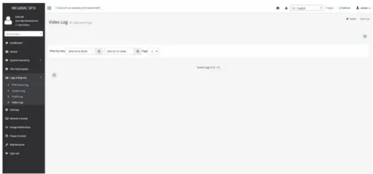
text_image
NEGARAC SP-X 12.5 FLTR AI & DBEY MELON IN EPC Host Online Quick Links... Dashboard Server System Environment Link Information Log & Requests SPAR Event Log System Log Build Log Video Log Settings Resource Control Image Reallocation Power Control Maintenance Sign and Video Log All vViewings/logs Filter by Date: 2018-03-06 00:00 - 2018-07-23 16:00 Page 1 Event Log 0 (8 - 5)
Video will be allowed to play/download only if file size is lesser than 40MB. Browsers have various memory restrictions, due to this browser cannot store and process data greater than 40MB (approximately). If file size is greater than 40MB, user will be notified with a message to use Java player Application.
2-6 Settings
This group of pages allows you to access various configuration settings. A screenshot of Configuration Group menu is shown below.

text_image
NEGARIC SP-X ISSUE 28 NEW COLDING WORK Host Online Space Links... Clearboard Sensor System inventory FPU information Log & Reports Settings Remote Control Image Reflective Power Controls Maintenance Sign out Settings Configure EMC users Capture Tools Data & Time User List User Services Web User Settings Log Settings Manage License Media Radio/Style Settings Network Settings PWM Order Settings Platform Demand Policy Services SMTP Settings Alt. Settings System Password User Management Video Recording Fan Profile Power Coverage USB InterfaceA detailed description of the Settings menu is given below.
2-6-1 Captured BSOD
This menu is used to display a snapshot of the blue screen captured at the time when/if the host system crashed since the last reboot. A sample screenshot of Captured BSOD is shown below.
Note: KVM service should be enabled to display the BSOD. This can be configured under Settings > Services > KVM.
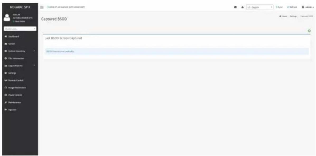
text_image
NEGARAC SP-X COSL30 AVR 2.001.0000.0000 • Next Online Check Loss... Default Server System Inventory File Information Logs & Requests Settings Remote Control Image/Internetline Power Control Maintenance Sign out Captured BSOD Last BSOD Screen Captured BSOD Screen is not available.2-6-2 Date & Time
This field is used to set the date and time on the BMC. A sample screenshot of Date & Time is shown below.
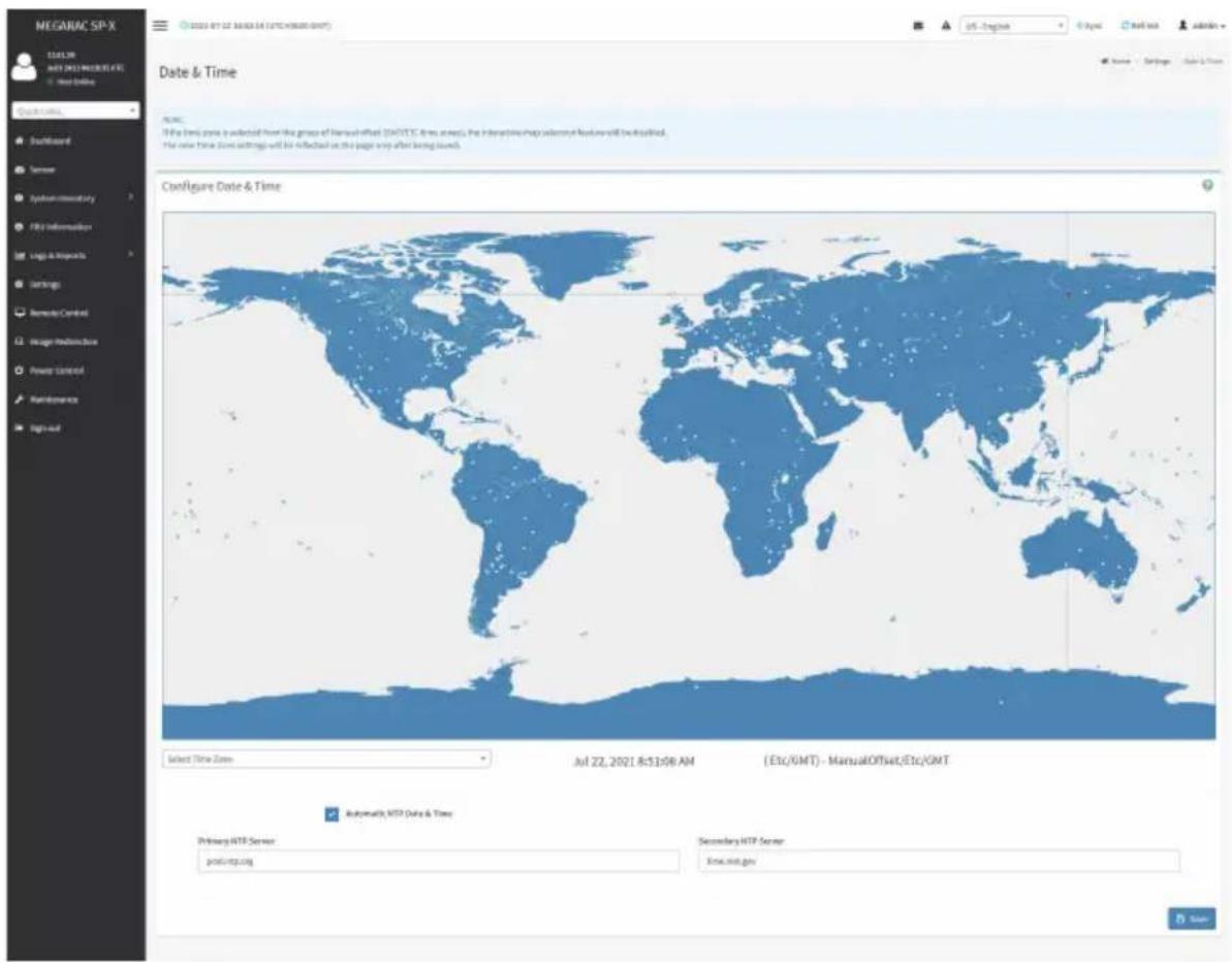
text_image
MEGARAC SP-X 11:30 AM MEGARAC SP-X New Online Quick time, Backboard Server System monitoring FBS Information Logic & Resources Settings Remote Control Image Modification Power Control Maintenance Sign-up Date & Time Configure Date & Time Select Time Zone Jul 22, 2021 8:51:59 AM (Etc/OMT) - ManualOffset/Etc/OMT Automaticly MTD Date & Time Primary HTTP Server post-irp.org Secondary HTTP Server Xmas.net.govThe Date & Time section consists of the following fields:
Configure Date & Time: Displays Time zone list containing the UTC offset along with the locations and Navigational line to select the location which can be used to display the exact local time.
Automatic NTP Date & Time: Automatically synchronizes Date and Time with the NTP Server. Primary NTP Server: Configures a primary NTP server to use when automatically setting the date and time.
Secondary NTP Server: Configures a secondary NTP server to use when automatically setting the date and time.
Save: Saves the configured settings.
Procedure
- Select the Time zone location from the map.
-
Enable Automatic NTP Date & Time.
-
In the Primary NTP Server / Secondary NTP Server field, specify the NTP server for the device.

Note: Secondary NTP server is optional field. If the Primary NTP server is not working fine, then the Secondary NTP Server will be used.
- Enable Automatic Date & Time option.
- Click Save button to save the settings.
2-6-3 External User Services
LDAP/E-Directory Settings
The Lightweight Directory Access Protocol (LDAP)/E-Directory Settings is an application protocol for querying and modifying data of directory services implemented in Internet Protocol (IP) networks.
In Web GUI, LDAP is an Internet protocol that BMC can use to authenticate users. If you have an LDAP server configured on your network, you can use it as an easy way to add, manage and authenticate BMC users. This is done by passing login requests to your LDAP Server. This means that there is no need to define an additional authentication mechanism, when using the BMC. Since your existing LDAP Server keeps an authentication centralized, you will always know who is accessing the network resources and can easily define the user or group- based policies to control access.
To open External User Services page, click Settings > External User Services from the menu bar. A sample screenshot of External User Services page is shown below.

text_image
MEGARAC SP-X IDAPR MAY 2021 NEWSPX User Online Quick Links... Dashboard Server System Inventory File Information Logic & Resources Settings Remode Control Usage/Redistribution Power Control Maintenance Tags out External User Services IDAPR Directory Settings Active Directory Settings RADIUS SettingsTo open LDAP/E-DIRECTORY Settings page, click Settings > External User Services > LDAP/E-Directory Settings from the menu bar.
A sample screenshot of External User Services page is shown below.

text_image
MEGARAC SP-X C:\Users\MIE\DATA\MIE\DATA\MIE\DATA\MIE\DATA\MIE\DATA\MIE\DATA\MIE\DATA\MIE\DATA\MIE\DATA\MIE\DATA\MIE\DATA\MIE\DATA\MIE\DATA\MIE\DATA\MIE\MIE\MIE\MIE\MIE\MIE\MIE\MIE\MIE\MIE\MIE\MIE\MIE\MIE\MIE\MIE\MIE\MIE\MIE\MIE\MIE\MIE\MIE\MIE\MIE\MIE\MIE\MIE\MIE\MIE\MIE\MIE\MIE\MIE\nLDAP/E-Directory Settings\nGeneral Settings\n Puzzle Groups\nName Settings External User Settings LDAP/E-Directory SettingsThe fields in the LDAP/E-Directory Settings page are explained below.
General Settings: Configures LDAP/E-Directory Settings. Options are Enable LDAP/E-Directory Authentication, IP Address, Port and Search base.
Role Groups: Adds a new role group to the device. Alternatively, double click on a free slot to add a role group.
Procedure
- In the LDAP/E-Directory Settings page, click General Settings. A sample screenshot of General LDAP Settings page is given below.

text_image
MEGARUC SP-X 100% AR AVR 2003/08/2019 (EPC) © Next Offline Quick URL... Default Server Systems Inventory Proxy Information Legal & Requests Set Rep Nevada Central Intage Infrastructure Power Control Maintenance Sign out General LDAP Settings Explain LDAPPS-Directory Authentication Inscription Type No Encryption ShareX Existential/Static Type IP Address PDB% Server Address Port: 265 Free: 0% e.g., e.g. e.g. e.g. e.g. e.g. e.g. e.g. e.g. e.g. e.g. e.g. e.g. e.g. e.g. e.g. e.g. e.g. e.g. e.g. e.g. e.g. e.g. e.g. e.g. e.g. e.g. e.g. e.g. e.g. e.g. e.g. e.g. e.g. e.g. a Access: Authentication and Received Search Date e.g., e.g. e.g. e.g. e.g. e.g. e.g. e.g. e.g. Attribute of User Login on Save US - English S.No. ReadoutAccess
Settings - Empirical User Settings - LDAPPS-Clamping Settings - General LDAP Settings- Click Enable LDAP/E-Directory Authentication, to enable LDAP/E-Directory Settings.
- Select the Encryption Type for LDAP/E-Directory.

Note: Configure the proper port number, when SSL is enabled.
-
Select the Common Name Type.
-
Enter the IP address of LDAP server in the Server Address field.

Note: IP Address made of 4 numbers separated by dots as in 'xxx.xxx.xxx.xxx'.
Each Number ranges from 0 to 255.
First Number must not be 0.
Supports IPv4 Address format and IPv6 Address format.
Configure FQDN address, when using StartTLS with FQDN.
- Specify the LDAP Port in the Port field.

Note: Default Port is 389.
For SSL connections, default port is 636.
The Port value ranges from 1 to 65535.
Port 80 is blocked for TCP/UDP protocols.
- Specify the Bind DN that is used during bind operation, which authenticates the client to the server.

Note: Bind DN is a string of 4 to 63 alpha-numeric characters.
It must start with an alphabetical character.
Special Symbols like dot(.), comma(,), hyphen(-), underscore(_) , equal-to(=) are allowed.
Example: cn=manager, ou=login, dc=domain, dc=com
- Enter the password in the Password field.

Note: Password must be at least 1 character long.
Blank space is not allowed.
This field will not allow more than 47 characters.
- Enter the Search Base. The Search base allows the LDAP server to find which part of the external directory tree to be searched. The search base may be something equivalent to the organization or the group of external directory.

Note: Search base is a string of 4 to 64 alpha-numeric characters.
must start with an alphabetical character.
Special Symbols like dot(.), comma(,), hyphen(-), underscore(_) , equal-to(=) are allowed.
Example: ou-login, dc-domain, dc-com
- Select Attribute of User Login to find the LDAP/E-Directory server which attribute should be used to identify the user.

Note: It only supports cn or uid.
- Select CA Certificate File from the Browse field to identify the certificate of the trusted CA certs.
- Select the CA Certificate File to find the client certificate filename.
- Select Private Key to find the client private key filename.
Note: All the 3 files are required, when StartTLS is enabled.

- Click Save to save the settings.
To add a new Role Group
- In the LDAP/E-Directory Settings page, click Role Groups and select a blank row.
- Click Add Role Group or alternatively double click on the blank row to open the Add Role group page as shown in the screenshot below.
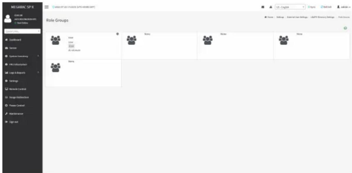
text_image
NEGARAC SP-X ECLUIER JAN'S RESEARCH & INC. Host Online Quick Links... Qualifiborant Sensor Systems Inventory mms manufacturers Logx & Reports Settings Remode Control Image Downloaders Power Control Maintenance Sign out 2021-07-22 17:13:03 (MTO-40080-08FT) Role Groups Driver Driver Board Devicewife Name Name Name Name- In the Group Name field, enter the name that identifies the role group.
Note: Role Group Name is a string of 64 alpha-numeric characters.
Special symbols hyphen and underscore are allowed.
- In the Group Domain field. Enter the Role Group Domain where the role group is located.
Note: Domain Name is a string of 4 to 64 alpha-numeric characters.
t must start with an alphabetical character.
Special Symbols like dot(.), comma(,), hyphen(-), underscore(_) , equal-to(=) are allowed.
Example: cn=manager, ou=login, dc=domain, dc=com
-
In the Group Privilege field, enter the level of privilege (User, Administrator, Operator, None) to assign to this role group.
-
Select one or both of the required options
-
KVM Access
-
VMedia Access
-
Click Save to save the new role group and return to the Role Group List.
Active Directory Settings
An active directory is a directory structure used on Microsoft Windows based computers and servers to store information and data about networks and domains. An active directory (sometimes referred to as AD) does a variety of functions including the ability to provide information on objects. It also helps to organize these objects for easy retrieval and access, allows access by end users and administrators and allows the administrator to set security up for the directory.
Active Directory allows you to configure the Active Directory Server Settings. The displayed table shows any configured Role Groups and the available slots. You can modify, add or delete role groups from here. Group domain can be the AD domain or a trusted domain. Group Name should correspond to the name of an actual AD group.
Note: To view the page, you must be at least a User and to modify or add a group, you must be an Administrator.
To open Active Directory Settings page, click Settings > External User Settings > Active Directory from the menu bar. A sample screenshot of Active Directory Settings page is shown below.

text_image
MEGARAC SP-X TITLE BY AUTH (2021) REACHS (F1) Next Online File Edit View... Institute Server Typewriter inventory TIFU information Logo & Image Settings Remode Control Insight Redisclosure Power Control Maintenance Tags out Active directory Settings Terminal Settings Role Database USE - English Logic Text file adminThe fields in the Active Directory page are explained below.
General Settings: Configures Active Directory General Settings. Options are Enable Active Directory Authentication, Secret User Name, Secret Password, User Domain Name, and up to three Domain Controller Server Addresses.
Role Groups: Adds a new role group to the device. Alternatively, double click on a free slot to add a role group.
Procedure
Entering the details in General Active Directory Settings page:
- Click on General Settings to open the General Active Directory Settings page.
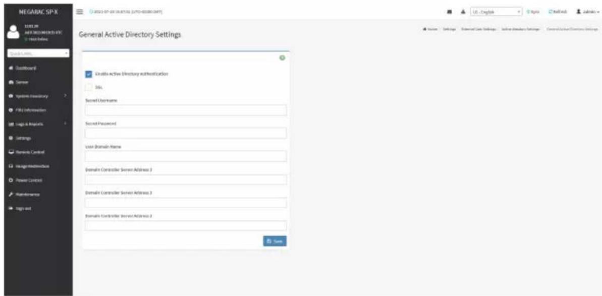
text_image
NEGARAC SP-X 100% OFF AUTO-DRAWINGS-8FC Test Online Quick Links LastBoard Server Systems Inventory File Information Logic & Requests Settings Remote Control Image Maintenance Power Control Maintenance Sign out General Active Directory Settings Creativa Active Directory authentication Std. Secret User Name Secret Password User Domain Name Domain Controller Server Address 3 Domain Controller Server Address 3 Domain Controller Server Address 2 Save USE - English Internet Core Settings Active Directory Settings Control Server Clients Settings- In the Active Directory Settings page, check/uncheck the Enable Active Directory Authentication check box to enable/disable Active Directory Authentication.

Note: If Active Directory Authentication is enabled, enter the required information access the Active Directory server.
- Specify the Secret user name and password in the Secret User Name and Secret Password fields respectively.

Note: Secret username/password for Active Directory is not mandatory. When secret name & password is empty, Authentication fails will be always treated as Invalid sword error.
For Invalid Password error PAM will not try other authentication methods. So it is recommended to keep Active Directory in the last location in PAM order.
User Name is a string of 1 to 64 alpha-numeric characters.
It must start with an alphabetical character.
It is case-sensitive.
Special characters like comma, period, colon, semicolon, slash, backslash, square brackets, angle brackets, pipe, equal, plus, asterisk, question mark, ampersand, double quotes, space are not allowed.
Password must be at least 6 character long and will not allow more than 127 characters.
-
Specify the Domain Name for the user in the User Domain Name field. E.g. MyDomain.com
-
Configure IP addresses in Domain Controller Server Address 1, Domain Controller Server Address 2 and Domain Controller Server Address 3.

Note: IP address of Active Directory server: At least one Domain Controller Server dress must be configured. IP Address made of 4 numbers separated by dots as in "xxx.xxx.xxx.xxx".
Each number ranges from 0 to 255.
First number must not be 0.
Domain Controller Server Addresses will supports IPv4 Address format and IPv6 Address format.
- Click Save to save the entered settings and return to Active Directory Settings page.
Role Groups
To open Role Group page, click Settings > External User Settings > Active Directory Settings > Role Groups from the menu bar. A sample screenshot of Role Groups page is shown below.

text_image
13.02.820 Aug 20 2021 01:51:00 UTC Host Online Quick Links... Dashboard Sensor System Inventory FRU Information Logs & Reports Settings Remote Control Image Redirection Power Control Maintenance Sign out Role Groups Home - Settings - External User Settings - Active directory Settings - Role Groups Midtest Administrator KVM VMedia sit.com None None None NoneThe fields in the Role Group page are explained below.
Role Group Name: The name that identifies the role group in the Active Directory.

Note: Role Group Name is a string of 64 alpha-numeric characters.
Special symbols hyphen and underscore are allowed.
Group Name: This name identifies the role group in Active Directory.

Note: Role Group Name is a string of 64 alpha-numeric characters.
Special symbols hyphen and underscore are allowed.
Group Domain: The domain where the role group is located.

Note: Domain Name is a string of 255 alpha-numeric characters.
Special symbols hyphen, underscore and dot are allowed.
Group Privilege: The level of privilege to assign to this role group.
KVM Access: Provides access to KVM for AD authenticated role group user.
VMedia Access: Provides access to VMedia for AD authenticated role group user.
To add a new Role Group
- In the Active Directory Settings page, select a Role Group and click Add Role Group or alternatively double click on the blank row to open the Add Role group page as shown in the screenshot below.

text_image
MEGARAC SP-X 15.01.39 AD 32 DWS14021-01 WRC DB/CB 16.027.204 © Float Options Quick Links Dashboard Sinaay System Inventory FIRE Information Logo & Reports Settings Remote Control Image RedSection Player Control Maintenance Signout © 2000-01-01 18:30:49 (S7C+00:09 UTC) Role Groups Group Name adjust Group Description sh.coms Group Profileges Administrator KVM Access kMedia Access Save US - English Sign Sendlog admin File Groups Role Groups Browse Settings External User Settings Active Directory Settings Role Groups Role Groups Activate Windows Go at Settings to access Windows- In the Group Name field, enter the name that identifies the role group in the Active Directory.

Note: Role Group Name is a string of 64 alpha-numeric characters.
Special symbols hyphen and underscore are allowed.
- In the Group Domain field, enter the domain where the role group is located.

Note: Domain Name is a string of 255 alpha-numeric characters. Special symbols /phen, underscore, and dot are allowed.
-
In the Group Privilege field, enter the level of privilege to assign to this role group.
-
Select the required options
-
KVM Access
-
VMedia Access
-
Click Save to add the new role group and return to the Role Group List.
To Delete a Role Group
- In the Role Groups Page, select the row that you want to delete.
- Click Delete Role Group.
RADIUS Settings
RADIUS is a modular, high performance and feature-rich RADIUS suite including server, clients, development libraries and numerous additional RADIUS related utilities.
In Web GUI, this page is used to set the RADIUS Authentication.
To open RADIUS Settings page, click Settings > External User Settings > RADIUS Settings from the menu bar. A sample screenshot of RADIUS Settings page is shown below.

text_image
NEGARAC SP-X CULS 30 JAN 9 DEB13MROKOS EFC Trust Online Quick Limits... QuickReward Sensor Typewriter Inventory Fits Influenzaion Logic & Resources Settings Remedy Control Storage Redistribution Power Control Maintenance Tags out 2021-07-22 17:16:18 (UTD-00380.GMT) RADIUS Settings Service RADIUS Settings Advanced RADIUS Settings Home - Settings - Terminal User Settings RADIUS SettingsThe fields in the General RADIUS Settings page are explained below.
Enable RADIUS Authentication: Option to enable/disable RADIUS authentication.
Server Address: The IP address of RADIUS server.

Note: IP Address (Both IPv4 and IPv6 format).
QDN (Fully Qualified Domain Name) format.
Port: The RADIUS Port number.

Note: Default Port is 1812.
Port value ranges from 1 to 65535.
Port 80 is blocked for TCP/UDP protocols.
Secret: The Authentication Secret for RADIUS server.

Note: This field will not allow more than 32 characters.
Secret must be at least 4 characters long.
Blank space is not allowed.
Enable KVM Access: This field provides access to KVM for RADIUS authenticated users.
Enable VMedia Access: This field provides access to VMedia for RADIUS authenticated users.
Save: Saves the configured settings.
Procedure
- Enable the RADIUS Authentication check box to authenticate the RADIUS.
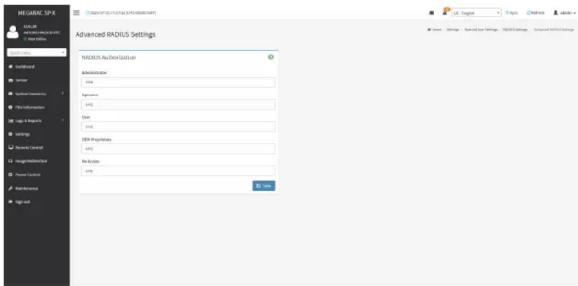
- Click Advanced RADIUS Settings. This opens the Radius Authorization window as shown below.
text_image
MEGARAC SP-X TITLE MAY'S 2021 MERCELS-IFC Host Online Quick Online... Dashboard Server Synthesis Inventory File Information Logs & Requests Settings Remarks Control Insight Hardware Power Control Maintenance Sign out Advanced RADIUS Settings RADIUS Authorization Administrator H34 Operator [UK] User [UK] DEP Proprietary [UK] Web Access [UK] Save Home Settings General User Settings RADIR Settings Advanced RADIR Settings
Note: For Authorization Purpose, configure the Radius user with Vendor Specific
ute on the server.
These fields will not allow more than 127 characters and the "#" sign is not allowed.
Example 1:
Add Vendor-Specific attribute
cd/usr/share/freeradius
vim dictionary.adtest
(Add content below)
# dictionary.adtest
VENDOR ADTest 58
# Standard attribute
BEGIN-VENDOR ADTest
ATTRIBUTE ADTest-group 1 string
END-VENDOR ADTest
vim dictionary
(Add this line)
\$INCLUDE dictionary.adtest
Example 2:
Add users
vim users
(add content below)
"RadiusTest1" Cleartext-Password:="000000"
Service-Type=Administrative-User,
Auth-Type:=System,
ADTest-group:="H=4"
- Click Save to save the changes made.
2-6-4 KVM Mouse Settings
In MegaRAC GUI, Redirection Console handles mouse emulation from local window to remote screen in either of three methods. User has to be an Administrator to configure this option. To view the Supported Operating Systems for Mouse Mode, click Mouse Mode.
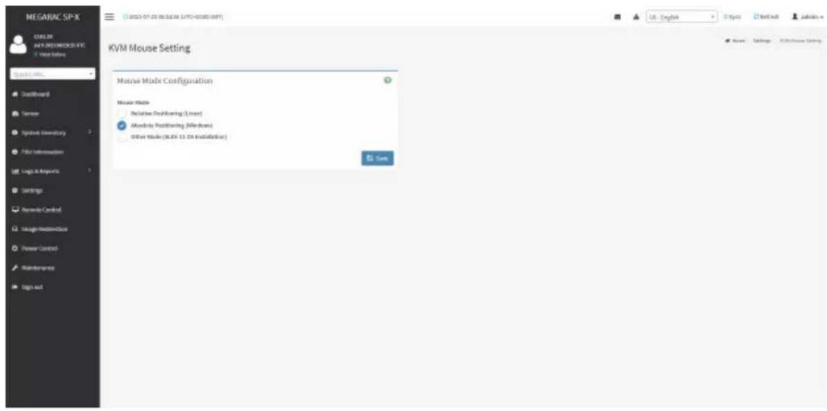
To open KVM Mouse setting page, click Settings > KVM Mouse Setting from the menu bar. A sample screenshot of KVM Mouse Settings page is shown below.
text_image
NEGAURC SP-X SQL Server NATI DEGREESO2.4V6 View Before Quick Links Default Board Sensor Symbol Directory File Information Logic & Response Settings Service Control Usage Infrastructure Power Control Maintenance Sign out KVM Mouse Setting Mouse Mode Configuration Mouse Mode Reclusive Rebuilding (User) Absolute Positioning (Redboard) Other Mode (36.85 13.09 Installation) Save Name Settings Additional SettingsThe fields in the KVM Mouse Settings page are explained below.
Relative Positioning (Linux): The relative mode sends the calculated relative mouse position displacement to the server.
Absolute Positioning (Windows): The absolute position of the local mouse is sent to the server. Recommended for Windows or later Linux releases.
Other Mode (SLES-11 OS Installation): Sends the calculated displacement from the local mouse in the center position to the server.
Save: Saves the current changes.
Procedure
- Choose either of the following as your requirement:
- Set to Absolute Positioning (Windows)

Note: Applicable for all Windows versions, versions above RHEL6, and versions above FC14.
- Set to Relative Positioning (Linux).

Note: Applicable for all Linux versions, versions less than RHEL6, and versions less FC14.
- Set to Other Mode (SLES-11 OS Installation).

Note: Recommended for SLES-11 OS Installation.
- Click Save button to save the changes made.
2-6-5 Log Settings
In MegaRAC GUI, System and Audit log page displays a list of system logs and audit logs occurred in this device.
To open the Log Settings page, click Settings > Log Settings from the menu bar.
A sample screenshot of Log Settings page is shown below.

text_image
MEGARAC SP-X 12.01.38 AVS NEW MEGARAC SPX Map Online Quick Links... Dashboard Server System Environment File Information Logic & Resources Settings Remode Control Intangible Resource Power Control Maintenance Sign out Log Settings SQL Log Settings Policy Advanced Log Settings USE - English Log Name: Settings Log SettingsThe fields in the Log Settings page are explained below.
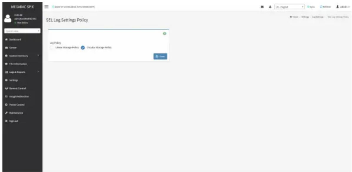
SEL Log Settings Policy
To open SEL Log Settings Policy page, click Settings > Log Settings > SEL Log Settings Policy from the menu bar. The SEL Log Settings Policy page is used to configure the log policy for the event log. A sample screenshot of SEL Log Settings Policy page is shown below.
text_image
MEGARAC SP-X MELSR AFS (MELSR)MOOS-ERC Host Online Quick Links... Dashboard Semner Digital Inventory File Information Logic & Resources Settings Semends Control Integrated DownloadBus Power Control Maintenance Sign out SEL Log Settings Policy Log Policy Linear Manage Policy Circular Manage Policy Game USE - English Log Settings SQL Log Settings PolicyAdvanced Log Settings
To open Advanced Log Settings page, click Settings > Log Settings > Advanced Log Settings from the menu bar. A sample screenshot of Advanced Log Settings page is shown below.
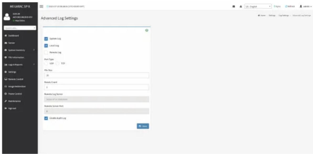
text_image
MEGARAC SP-X 12.01.28 AVPS 2023 MODELS V6C File Online Quick Links... Dashboard Server Synbase Inventory File Information Logic & Resources Settings Remode Control Usage Modemodbus Power Control Maintenance Tags out Advanced Log Settings System Log Local Log Remote Log Port Type USB TCP File Size 28 Remote Count 8 Remote Log Server "Default" or "Default" status Remote Server Port 8 Enable Audit Log Home Settings Log Settings - Additional Log SettingsThe fields in the Advanced Log Settings page are explained below.
System Log: Check/uncheck to enable/disable the System Logs.
Local Log: Select local log to save the logs locally (BMC).

Note: Local file resides at /var/log/
Remote Log: Select remote log to save the logs in a remote machine.
Port Type: When Remote Log is enabled, user can select either UDP or TCP per requirement.
File Size: This field is to specify the size of the file in bytes if the selected log type is local.

Note: Size ranges from 3 to 65535. Log files are rotated when they grow bigger than
Rotate Count: Backs up the log information in back up files.

Note: Values supported are 0 and 1.
When log information exceeds the file size, the old log information is automatically moved to back up files based on the rotate count value. If rotate count is zero, then old log information gets cleared permanently.
File Size and Rotate Count options will be available only when Local Log is enabled.
Remote Log Server: This field is to specify the remote server address to log the system events.

Note: Server address will support the following:
Pv4 and IPv6 address format.
PQDN (Fully qualified domain name) format.
Remote Server Port: This field is to specify the remote server port to log the system events.

Note: Remote Log Server and Remote Server Port options will be available only when Remote Log is enabled.
Enable Audit Log: Enables/Disables the audit log.
Save: Saves the current changes.
Procedure
- In the System Log field, enable or disable the option.
- Select the Log type: Local Log or Remote Log.
- If Local Log is selected, enter the file size in the File Size field and rotate count in the Rotate Count field.

Note: If Remote Log is selected, the fields file size and rotate count need not be mentioned.
- If Remote Log is selected, specify the Port Type, Remote Log Server, and Remote Server Port.
- In the Audit Log field, check or uncheck the Enable option as needed.
- Click Save to save the changes.
2-6-6 Manage Licenses
This page displays available licenses for this system and the validity period of the licenses. To open the Manage Licenses page, click Settings > Manage Licenses from the menu bar. A sample screenshot of Manage Licenses page is shown below.

text_image
MEGARAC SP-X URL:28 JAP 9 DEUT MEGARAC SPX Host Online Quick URL: Dustboard Sensor Logbook Inventory File Information Logic & Algorithms Settings Remode Control Storage/Reconstruction Power Control Maintenance Tag out Manage Licenses View License Add License Key USE English Topic Readout Admin Finish Settings Manage CommonThe fields in the Manage Licenses page are explained below.
View Licenses: Displays the available licenses and the validity period of the licenses.
Add License Key: Select to add a license key.
2-6-7 Media Redirection Settings
This page is used to configure the media into BMC for redirection. To open the Media Redirection page, click Settings > Media Redirection Settings from the menu bar.
A sample screenshot of Media Redirection page is shown below.

text_image
MEGARAC SP-X ELELTR A45.2013M80005-ETC Show Online Quick Limits... Qualiforand Sensor Symbol inventory File information Logic & Resources Settings Remedy Control Image Redirections Power Control Maintenance Sign out Media Redirection General Settings Used in instance Settings Remote Services Active Release/InstallThe fields in the Media Redirection page are explained below.
General Settings
This option is used to configure General Media Settings. To open the General Media Settings section, click Settings > Media Redirection Settings > General Settings.
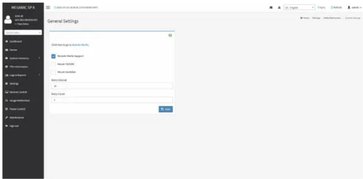
text_image
MEGARAC SP-X 12.01.28 MAY 2023 MEGARAC SP-X File Online Quick Links... Dashboard Server Syncbase inventory File information Logic & Resources Settings Remode Central Insight/Rebeobloxus Power Control Maintenance Tags out General Settings Click here to go to license Media. Measures Media TapgedT Microsoft CE/DVD Microsoft Handbitik Back Event 26 Back Count 3 Save Home Settings Media Delivery Control General SettingsRemote Media Support: Enables/Disables Remote Media support, check/uncheck the box. Remote Media emulates CD/DVD/HDD images as media through BMC.
Mount CD/DVD: Enables/Disables Mount CD/DVD support, check/uncheck the check box.

Note: You can also select all the media types simultaneously.
Server Address for CD/DVD Images: Displays the address of the server where the remote media images are stored.
Path in server: Displays the source path to the remote media images.
Share Type for CD/DVD: Selects the Share Type of the remote media server either NFS, CIFS, or HTTP.
Domain Name, Username, and Password: If share type is CIFS, then enter user credentials to authenticate on the server.
Same settings for Harddisk Images: Enable/Disable to select same media type data configurations for all the remote media types.
Mount Harddisk: Enable/Disable to Mount Harddisk.
Server Address for Harddisk Images: Address of the server where the remote media images are stored.
Path in server: Displays the source path to the remote media images.
Share Type for Harddisk: Selects the Share Type of the remote media server either NFS, CIFS, or HTTP.
Domain Name, Username, and Password: If share type is CIFS, then enter user credentials to authenticate on the server.
Retry Interval: Gives time interval for each attempt to reconnect Remote Media.
Retry Count: Specifies the number of attempts to reconnect Remote Media.
Save: Saves the configurations.
VMedia Instance Settings
This page is used to configure Virtual Media device settings. To open the VMedia Instance Settings page, click Settings > Media Redirection Settings > VMedia Instance Settings from the menu bar.
A sample screenshot of VMedia Instance Settings page is shown below.
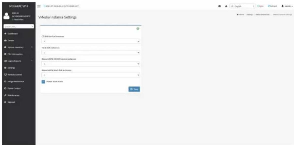
text_image
MEGARAC SP-X COLOR MENI NEDIMIKOS IFC File Online Space Links... Installboard Server Spdbus inventory File information Logic & Algorithms Settings Remode Control Insight Infrastructure Power Control Maintenance Sign out VMedia Instance Settings C:\WINDOWS\device\instances 4 main disk instances 1 Reclusive PWM CD/DVD device instances 3 Reclusive PWM Head disk instances 1 Power Start Menu Save US - English Google Networks Adobe+ 50%+ 20%+ 10%+ 50%+ 10%+ 50%+ 10%+ 50%+ 10%+ 50%+ 10%+ 50%+ 10%+ 50%+ 10%+ 50%+ 10%+ 50%+ 10%+ 50%+ 10%+ 50%+ 10%+ 10%+ 50% Name: Settings: Web/Description: Web/Source SettingsThe following fields are displayed in this page:
CD/DVD device instances: The number of CD/DVD devices supported for Virtual Media redirection.
Harddisk instances: The number of hard disk devices supported for Virtual Media redirection.
Remote KVM CD/DVD device instances: The number of CD/DVD devices supported for KVM Virtual Media redirection.
Remote KVM Hard disk instances: The number of hard disk devices supported for KVM Virtual Media redirection.
Power Save Mode: Enables/Disables the virtual USB devices visibility in the host. If this option is enabled, Virtual media devices will be connected to the Host machine only at the instance launching KVM session. If this option is disabled, Virtual media devices will remain connected to the host machine all the time irrespective of KVM session status.
Save: Saves the configured settings.

Note: Virtual Media configuration changes will restart all the media services. So configuration changes will be blocked when any active media redirection is present.
Procedure
- Select the number of CD/DVD devices, harddisk devices and remote KVM CD/DVD and hard disk devices from the respective drop-down list.

Note: Maximum of four devices can be added in CD/DVD and Harddisk drives.
- Check/uncheck the Power Save Mode option to enable/disable the virtual USB devices visibility in the host.
- Click Save to save the changes made.
Remote Session
In MegaRAC, this page is used to configure Remote Session configuration settings. KVM Single Port Application is enabled by default.
To open the Remote Session page, click Settings > Media Redirection Settings > Remote Session from the menu bar.
A sample screenshot of Remote Session page is shown below.
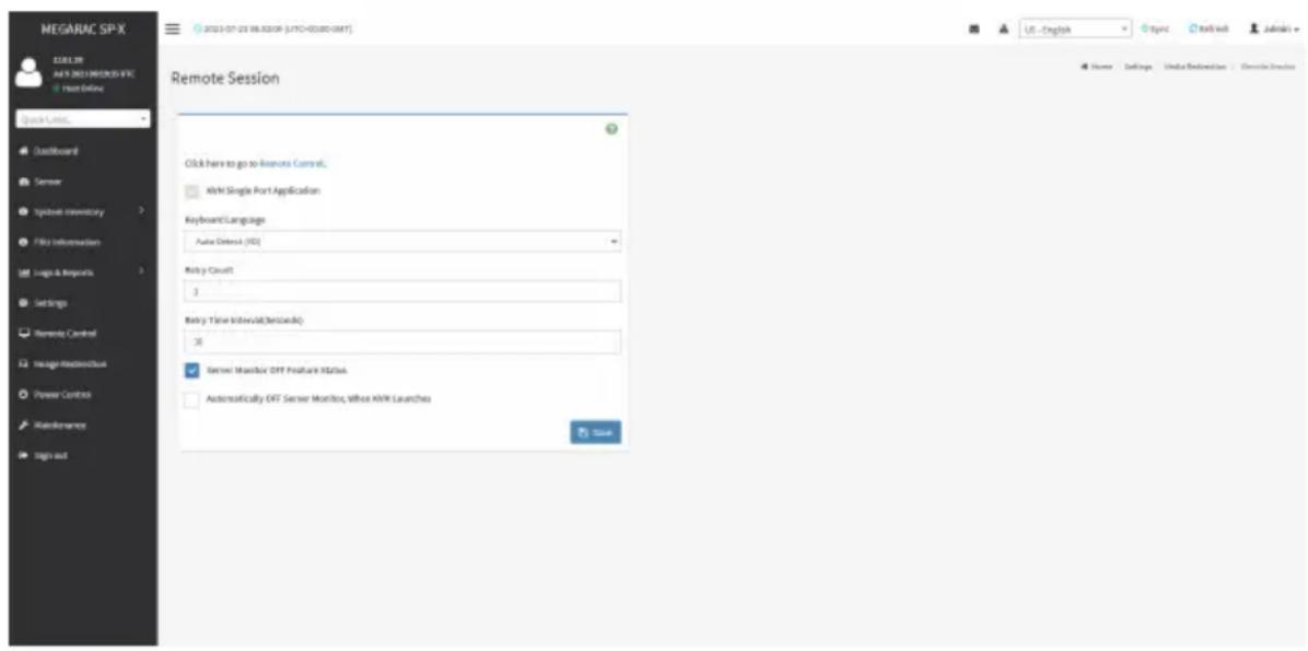
text_image
MEGARAC SP-X 123.38 A4-F 2021 MEGARAC SP-X Show Online Quick Links... Dustboard Server Logbook inventory File Information Logic & Impacts Settings Remends Control Image Monitoring Power Control Maintenance Sign out 2021-07-23 06:53:09 (LPTC+03080-0MT) Remote Session Click here to go to Remote Control. USB Single Port Application Keyboard/Language Auto Detect (ISO) Risky Count 3 Risky Time Interval(>|setpoint| ) 35 Server Monitor OTT Feature Status Automatically ORT Server Monitor, Without USB Launches SaveThe fields in the Configure Remote Session page are explained below.
KVM Single Port Application: This item is checked (enabled) by default and is not configurable. The KVM session will not use its dedicated port whereas both Web and KVM sessions will be established only via Web Port.
Keyboard Language: Select the keyboard supported languages.
Retry Count: Retries the redirection session for certain number of attempts.
Retry Time Interval (Seconds): Gives time interval for each attempt.
Server Monitor OFF Feature Status: Enables/Disables Server Monitor OFF. If this option is enabled, you can Lock or Unlock the Local host monitor from the remote KVM window. If this option is disabled, you cannot Lock or Unlock the Local host monitor from the remote KVM window.
Automatically OFF Server Monitor, When KVM Launches: Enables/Disables Automatically OFF Server Monitor, When KVM Launches.
Save: Saves the current changes.

Note: It will automatically close the existing remote redirection either KVM or Virtual via sessions on Single Port enable/disable.

Note: Installation of Operating System on the servers via BMC CD ISO image over note KVM may take 1 to 2 hours.
Procedure
- Check or uncheck the KVM Single Port Application option to enable Single Port Application support in BMC.
- Choose the Keyboard Language from the list of keyboard supported languages.
- Enter a value in the Retry Count field to set the number of attempts for retrying the redirection session.
- Enter a value in the Retry Time Interval (Seconds) field to give time interval for each attempts.
- Check the Server Monitor OFF Feature Status check box to enable Local Monitor ON/OFF command during runtime.
- Check the Automatically OFF Server Monitor, When KVM Launches check box to automatically Lock the local monitor during H5Viewer launch.
- Click Save to save the current changes.
Active Redirections
This page displays a list of Media which are being redirected currently. It shows current status and other basic information about the Media.
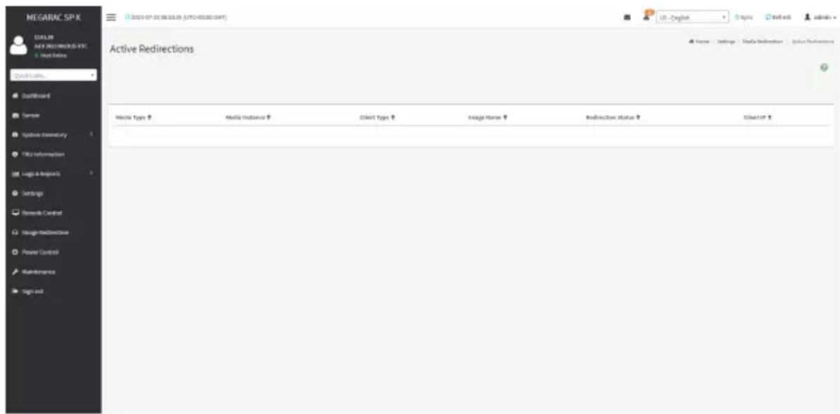
text_image
NEGARAC SP-X 12.01.08 ANY NEGARAC SP-X Host Online Quick Links... Dashboard Server Analysis Inventory File Information Logic & Requests Settings Remode Control Image-Redirectional Power Control Maintenance sign out Active Redirections Media Type ↑ Media Instance ↑ Client Type ↑ Image Name ↑ Redirectional Status ↑ Client ID ↑2-6-8 Network Settings
The Network Settings page is used to configure the network settings for the available LAN channels. It also allows users to manage the DNS settings or configure Network Controller Sideband Interface of a device. To open the Network Settings page, click Settings > Network Settings from the menu bar.
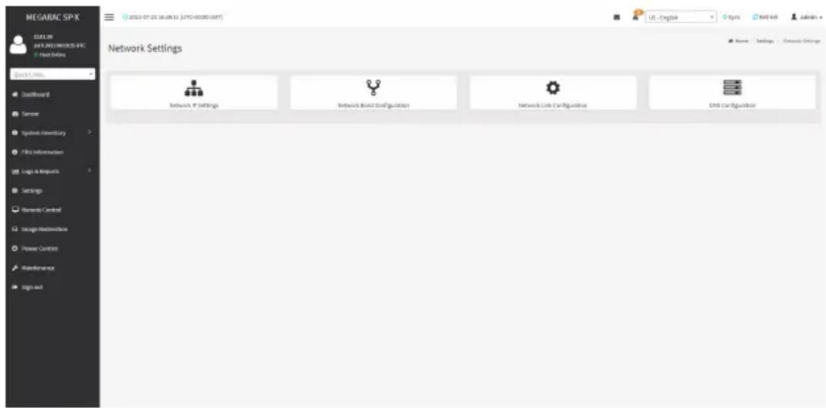
text_image
NEGARAC SP-X CELL 36 JAS 2013 NETWORKS-IFC Host Online Quick Links... DustBoard Sensor Systems Inventory File Information Logic & Network Settings Remarks Control Image Infrastructure Power Control Maintenance Sign out Network Settings Network IP Settings Network Based Configuration Network Link Configuration DMI ConfigurationNetwork IP Settings
To open Network IP Settings page, click Settings > Network Settings > Network IP Settings from the menu bar. A sample screenshot of Network IP Settings page is shown below.
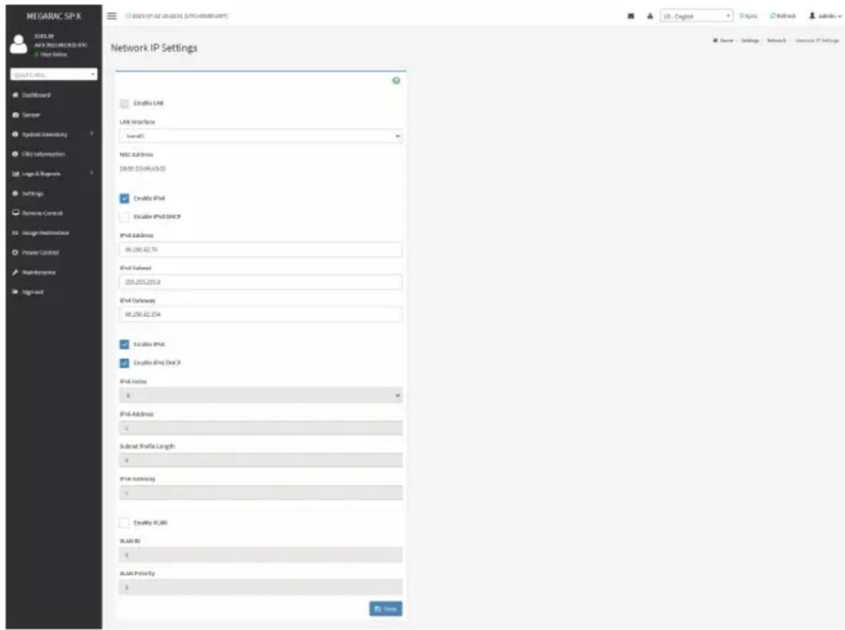
text_image
MEGARAC SP-X EELTR MFS NELLINICOS EPL File Online Quick Links... Dashboard Sensor Integrated Inventory My Information Language & Resources Settings Remove Control Image Realdehyde Power Control Maintenance Sign out Network IP Settings Enable LAN LAN Interface Iswal0 MAC Address: DATE: 05/06/03:03 Enable IPv4 Enable IPv2 DHCP IPv4 Address: 68.250.42.70 IPv4 Platform: 255.255.255.8 IPv4 Gateway: 68.250.42.254 Enable IPv4 Enable IPv2 DHCP IPv4 Index: 0 IPv4 Address: 0 Subnet Profile Length: 0 IPv4 Connection: 0 Enable IPv4 EPLTR ID: 0 EPLTR Priority: 0 Source - Settings - Network - Research IP SettingsThe fields in the Network IP Settings page are explained below.
Enable LAN: Enables/disables the LAN Settings.
LAN Interface: Lists the LAN interfaces.
MAC Address: Displays the MAC Address of the device. This is a read only field.
Enable IPv4: Enables/disables the IPv4 settings in the device.
Enable IPv4 DHCP: Enables IPv4 DHCP support for the selected interface.
IPv4 Address, IPv4 Subnet, and IPv4 Default Gateway: These fields are for specifying the static IPv4 address, Subnet Mask and Default Gateway to be configured to the device.

Note: IP Address made of 4 numbers separated by dots as in "xxx.xxx.xxx.xxx".
Each Number ranges from 0 to 255.
First Number must not be 0.
Enable IPv6: Enables/disables the IPv6 configuration settings.
Enable IPv6 DHCP: Enables/disables the IPv6 settings in the device. It dynamically configures IPv6 address using DHCP (Dynamic Host Configuration Protocol).
IPv6 Index: Specifies a static IPv6 Index to be configured to the device. E.g.: 0
IPv6 Address: Specifies a static IPv6 address to be configured to the device. E.g.: 2004::2010
Subnet Prefix Length: Specifies the subnet prefix length for the IPv6 settings.

Note: Value ranges from 0 to 128.
IPv6 Gateway: Specifies IPv6 default gateway.

Note: If core feature IPV6_COMPLIANCE is enabled, the IPV6 default Gateway field will e displayed.
Clear IPv6 Address: Check to clear the IPv6 address.
Enable VLAN: Enables/Disables the VLAN support for selected interface.
VLAN ID: The Identification for VLAN configuration.

Note: Value ranges from 1 to 4094.
LAN ID cannot be changed without resetting the VLAN configuration.
VLAN Priority: The priority for VLAN configuration.

Note: Value ranges from 0 to 7.
the highest priority for VLAN.
Save: Saves the entries.
Procedure
- Check Enable LAN to enable LAN support for the selected interface.
- Select the LAN Interface to be configured.
- Check Enable IPv4 to enable IPv4 support for the selected interface.
- Check Enable IPv4 DHCP to dynamically configure IPv4 address using DHCP.
- If the field is disabled, enter the IPv4 Address, IPv4 Subnet and IPv4 Default Gateway in the respective fields.
- In IPv6 Configuration, if you want to enable the IPv6 settings, check Enable IPv6.
- If the IPv6 setting is enabled, enable or disable the option Enable IPv6 DHCP.
- If the field is disabled, enter the IPv6 Index, IPv6 Address, Subnet Prefix length and IPv6 Gateway in the given field.
- In VLAN Configuration, if you want to enable the VLAN settings, check Enable LAN.
- Enter the VLAN ID in the specified field.
- Enter the VLAN Priority in the specified field.
- Click Save to save the entries.
Network Bond Configuration
To open the Network Bond Configuration page, click Settings > Network Settings > Network Bond Configuration from the menu bar. A sample screenshot of Network Bond Configuration page is shown below.

text_image
MEGARAC SP-X NEW NEXEERLEDOS-FRC Host Online Quick Links... Draftboard Semene Hydrofoil Inventory Fits Information Logic & Resources Settings Bemode Control Usage-Head/Drivebox Power Control Maintenance Sign out 2023-07-23 16:36:00 [JYTC-05080-0541] Network Bond Configuration Enable Boarding Auto-Configuration Bond Interface 4050 Bond Mode: active-backup Save Home Settings Database Resource Bond ConfigurationsThe fields in the Network Bond Configuration page are explained below.
Enable Bonding: Check to enable network bonding.

Note: If VLAN is enabled for any slave interfaces, Bonding cannot be enabled.
isable VLAN, go to Configuration > Network > VLAN.
Auto Configuration: Check to enable automatic configuration of network interfaces.
Bond Interface: Configures bonding for network interfaces.

Note: A minimum of two network interfaces is required to enable Network Bonding for device.
Bond Mode: Displays the network bonding mode in effect. This field is not configurable.
Save: Saves the entries.
Procedure
- Check Enable Bonding to enable network bonding for the network interfaces.
- Check Auto Configuration to enable automatic combination of network interfaces.
- Select a bond interface.
- Click Save to save the entries.
Network Link Configuration
To open Network Link Configuration page, click Settings > Network Settings > Network Link Configuration from the menu bar. A sample screenshot of Network Link Configuration page is shown below.

text_image
MEGARAC SP-X LEBLER MAYE NEELIMICS-INFO Host Online Quick Links... Draftboard Server Hybridest Inventory Fits Information Logic & Response Settings Bemends Control Language Monitoring Power Control Maintenance Tags out Network Link Configuration LAR Interface info0 Auto Regression Link speed 300Mbps Degree Mode Multi-Duplex Half Claplex SaveThe fields in the Network Link Configuration page are explained below.
LAN Interface: Select a network interface.
Auto Negotiation: Check to enable automatic negotiation.
Link Speed: Configures the link speed.

Note: The link speed can be 10, 100, or 1000 Mbps.
speed of 1000 Mbps is not applicable when Auto Negotiation is disabled.
Duplex Mode: Select the duplex mode.

Note: This setting option cannot be configured if Auto Negotiation is enabled.
Save: Saves the entries.
Procedure
- Select a network interface you want to configure from LAN Interface.
- Check Auto Negotiation to enable automatic configuration.
- Configure the link speed.

Note: This setting option cannot be configured if Auto Negotiation is enabled.
- Select the duplex mode.
- Click Save to save the entries.
DNS Configuration
The Domain Name System (DNS) is a distributed hierarchical naming system for computers, services, or any resource connected to the Internet or a private network. It associates the information with domain names assigned to each of the participants. Most importantly, it translates domain names meaningful to humans into the numerical (binary) identifiers associated with networking equipment for the purpose of locating and addressing these devices worldwide. The DNS Server settings page is used to manage the DNS settings of a device. To open DNS Server Settings page, click Settings > Network Settings > DNS Configuration from the menu bar. A sample screenshot of DNS Configuration page is shown below.

text_image
MEGARAC SP-X ELELIR MFS 2021/08/2015 EPC Host Online Quick Links Dashboard Service Systems Inventory FBS Information Logic & Resources Settings Beware Control Insight Mechanical Power Control Maintenance Sign out DNS Configuration DNS Enabled noDNS Enabled Host Names Setting Automatics Manual Host Names ANDIRECTSOSUNDED BAC Registration Settings BAC Interface: Monitor Register BAC Registration Method Phosphate DHCP Client PSBR Formatene TSHS-Configuration Trans Authentication Studied Current TSHS-Private File Info Not Available New TSHS-Private File Domain Setting Automatics Manual Domain Name: digital-in-103a Database Name Inset Setting Automatics Manual DNS Inset 1 36.1.3.0 DNS Server 2 : DNS Server 3 : Name Settings Network Settings USB ConfigurationDomain Name Service Configuration
DNS Enabled: Enables/Disables all the DNS Service configurations.
mDNS Enabled: Enables/Disables Multicast DNS.
Host Name Setting: Choose either Automatic or Manual settings.
Host Name: It displays host name of the device. If the Host setting is chosen as Manual, then specify the host name of the device.

Note: Value ranges from 1 to 64 alpha-numeric characters.
Special characters '-'(hyphen) and '-' (underscore) are allowed. It must not start or end with a '-' (hyphen). IE browsers won't work correctly if any part of the host name contain underscore (_) character.
BMC Registration Settings
BMC Interface: Options to register the BMC through the interfaces (eth0 & eth1).
Register BMC: Registers BMC through registration method.
Registration Method: Options to register the BMC are through Nsupply or DHCP Client FQDN or Hostname.
TSIG Configuration
TSIG Authentication Enabled: Check this box to enable TSIG authentication while registering DNS via nsupdate. Separate TSIG files can be uploaded for each LAN interface.
Current TSIG Private File: The information of current TSIG private file along with its uploaded date/time will be displayed (read-only).
New TSIG Private File: Browse and navigate to the TSIG private file.

Note: TSIG file should be of private type.
Domain Setting
Automatic: If you select Automatic, the Domain Name cannot be configured as it will be done automatically. The field will be disabled.
Manual: If the Domain Setting is chosen as Manual, then specify the domain name of the device.

Note: If you select Automatic, it displays the Domain interface option. If you selectUAL, it displays domain name.
Domain Name: It displays the domain name of the device.
Domain Name Server Setting
Automatic: If you select Automatic, the DNS Interface option should be explained.
Manual: Specify the DNS (Domain Name System) server address to be configured for the BMC.
IP Priority:
- If IP Priority is IPv4, it will have 2 IPv4 DNS servers and 1 IPv6 DNS server.
- If IP Priority is IPv6, it will have 2 IPv6 DNS servers and 1 IPv4 DNS server.

Note: This is not applicable for Manual configuration.
DNS Server 1, 2 & 3
To specify the DNS (Domain Name System) server address to be configured for the BMC.

Note: IPv4 Addresses should be given in dotted decimal representation.
Addresses are supported and must be global unicast addresses.
DNS Server Address will support the following:
- IPv4 Address format.
- IPv6 Address format.
Save: Saves the current changes.
Procedure
- Check the option DNS Enabled to enable all the DNS Service configurations.
- Check the option mDNS Enabled to enable Multicast DNS.
- Choose the Host Name Setting either Automatic or Manual.

Note: If you choose Automatic, you need not enter the Host Name and if you choose equal, you need to enter the Host Name.
- Enter the Host Name in the given field if you have chosen Manual Configuration.
- Under Register BMC, choose the BMC's network port to register with DNS settings.
-
Check Register BMC to register with DNS settings.
-
Nsupdate - Choose Nsupdate option to register with DNS server using nsupdate application.
- DHCP Client FQDN - Choose DHCP Client FQDN option to register with DNS Server using DHCP option 81.
- Hostname - Choose Hostname option to register with DNS server using DHCP option 12.

Note: Hostname option should be selected, if the DHCP client FQDN option is not reported by DHCP server.
-
In TSIG Configuration, check TSIG Authentication Enabled enable TSIG authentication while registering DNS via nsupdate.
-
The current file name will be displayed in Current TSIG Private file info field.
-
To view a new one, click New TSIG private file to browse and navigate to the TSIG private file.
-
In Domain Settings,
-
Select the domain settings (Automatic or Manual).
-
Enter the Domain Name in the given field if the option. Manual is being selected in domain settings field.
-
In Domain Name Server Setting,
-
Select the DNS Name Server Setting (Automatic or Manual).
- Choose the IP Priority, either IPv4 or IPv6.
-
Enter the DNS Server address.
-
In DNS Server 1, DNS Server 2 and DNS Server 3, enter the server addresses to be configured for the BMC.
-
Click Save to save the entries.
2-6-9 PAM Order Settings
This page is used to configure the PAM ordering for user authentication in to the BMC.
To open PAM Ordering page, click Settings > PAM Order Settings from the menu bar. A sample screenshot of PAM Order page is shown below:

text_image
NEGARAC SP-X URL: 01-23-17.0765 (LTD-03380.047) PAM Order PAM authorized/Carbox Order IPDB LOWF ACTIVE DIRECTORY ADDRESS SaveThe fields in the PAM Order page are explained below.
PAM Authentication Order: It shows the list of available PAM modules supported in BMC.

Note: It is recommended to not to keep same username for different PAM modules. thentication fails, the reason of fail could be invalid User or Invalid Password.
If Radius Authentication fails, we can't differentiate whether it is invalid user or invalid password. So it is always treated as Invalid username error and PAM will try other Authentication Methods.
If AD contains secret username & password as empty, Authentication fails will be always treated as Invalid Password error. For Invalid Password error PAM will not try other Authentication Methods. So it is recommended to keep AD in the last location in PAM order.
Save: Saves the configuration.
Procedure
- Select the required PAM module and click and drag the required PAM module. It can be moved UP or DOWN to change its arrangement order.
- Click Save to save any changes made.

Note: Whenever the configuration is modified, the web server will be restarted matically. Logged-in session will be logged out.
2-6-10 Platform Event Filter
Platform Event Filter (PEF) provides a mechanism for configuring the BMC to take selected actions on event messages that it receives or has internally generated. These actions include operations such as system power-off, system reset, as well as triggering the generation of an alert.
To open PEF Management Settings page, click Settings > Platform Event Filter from the menu bar.
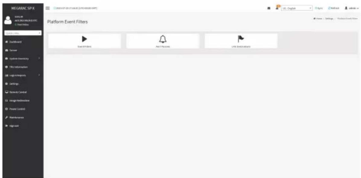
text_image
MEGARAC SP-X MIGELB AI & JOELENE VIT Deep Online Quick Links... Dashboard Server System-Inventory File Information Logic & Improve Settings Network Control Usage-Modinance Power Control Maintenance Sign out Platform Event Filters Add EPTOINS Add PPTOINS LPS Distributions Home Settings Machine Event FilterEvent Filters
A PEF implementation is recommended to provide at least 40 entries in the event filter table. A subset of these entries should be pre-configured for common system failure events, such as over-temperature, power system failure, fan failure events, etc. Remaining entries can be made available for 'OEM' or System Management Software configured events. Note that individual entries can be tagged as being reserved for system use - so this ratio of pre-configured entries to run-time configurable entries can be reallocated if necessary.
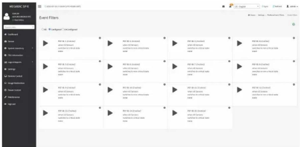
text_image
NEGAURC SPX DATA: 2023-07-25 (UNIVERSITY) (UNIVERSITY OF IT) Event Filters Quick Links... Default Board Server Symbol summary File Information Logo & Requests Settings Remote Control Integrant Release Power Control Maintenance Sign out Event Filters All Configured Low Configured PPT ID: 1 (Existing) when all servers switches to critical state name PPT ID: 2 (Existing) when all servers switches to non-critical state name PPT ID: 3 (Existing) when all servers switches to critical state name PPT ID: 4 (Existing) when all servers switches to non-critical state name PPT ID: 5 (Existing) when all servers switches to critical state name PPT ID: 6 (Existing) when all servers switches to non-critical state name PPT ID: 7 (Existing) when all servers switches to critical state name PPT ID: 8 (Existing) when all servers switches to non-critical state name PPT ID: 9 (Existing) when all servers switches to critical state name PPT ID: 10 (Existing) when all servers switches to non-critical state name PPT ID: 11 (Existing) when all servers switches to critical state name PPT ID: 12 (Existing) when all servers switches to non-critical state name PPT ID: 13 (Existing) when all servers switches to critical state name PPT ID: 14 (Existing) when all servers switches to non-critical state name PPT ID: 15 (Existing) when all servers switches to critical state nameThe fields in the Platform Event Filters tab are explained below. This page contains pre-configured 40 events with PEF IDs.
Procedure
- Click the Event Filters section to configure the event filters in the available slots.
- To add an Event Filter entry, select a free section to open the Event Filter entry page. A sample screenshot of Event Filter Configuration page is shown below.
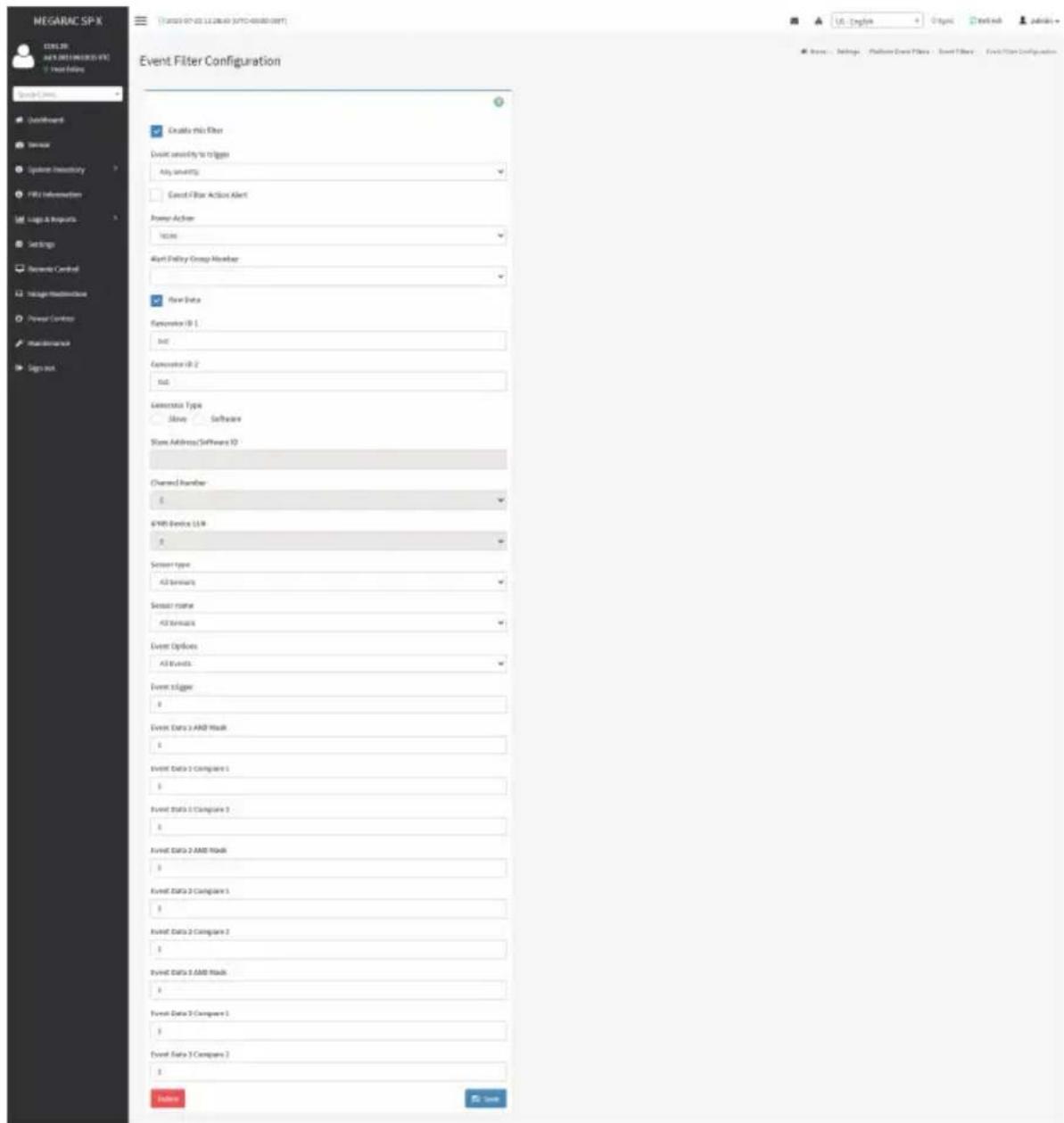
text_image
NEGARAC SP-X CENSER ANY DREAMS (F5) Treat History Event Filter Configuration Enable this filter Event sensitivity to triggers Any settings Cancel Filter Action Alert Power Action Access Alert Delivery Group Member Flow Data Generator ID 1 ID2 Generator ID 2 ID3 Generator Type Slave Software Show Address/Software ID Channel Number 0 64KB Device LLC 0 Sensor type 42 formats Sensor name 42 formats Event Options All Events Event XLogo 0 Event Data 3 AND Read 0 Event Data 2 Compare 1 0 Event Data 3 Compare 3 0 Event Data 2 AND Read 0 Event Data 3 Compare 1 0 Event Data 3 Compare 2 0 Event Data 3 AND Read 0 Event Data 2 Compare 1 0 Event Data 3 Compare 2 0 Options HelpIn the Event Filter Configuration section:
- In Enable this filter, check this option to enable the PEF settings.
• In Event Severity to trigger, select any one of the Event severity from the list. - Check Event Filter Action Alert to enable alerts for event filter actions.
- Select any one of the Power Action either Power down, Power reset or Power cycle from the drop down list

- Choose any one of the configured Alert Policy Group Number from the drop down list.
Note: Alert Policy has to be configured under Settings > PEF > Alert Policy.

- Check Raw Data option to fill the Generator ID with raw data.
- Generator ID 1 field is used to give raw generator ID 1 data value.
- Generator ID 2 field is used to give raw generator ID 2 data value.
Note: In RAW data field, specify hexadecimal value prefix with '0x'.
- In the Event Generator section, choose the event generator as Slave Address - if event was generated from IPMB. Otherwise as System Software ID - if event was generated from system software.
- In the Slave Address/Software ID field, specify corresponding I2C Slave Address or System Software ID.
- Choose the particular Channel Number that event message was received over. Or choose '0' if the event message was received via the system interface, primary IPMB, or internally generated by the BMC.
- Choose the corresponding IPMB Device LUN if event is generated by IPMB.
- Select the Sensor type of sensor that will trigger the event filter action.
• In the Sensor name field, choose the particular sensor from the sensor list. - Choose Event Option to be either All Events or Sensor Specific Events.
- Event Trigger field is used to give Event/Reading type value.
Note: Value ranges from 0 to 255.

- Event Data 1 AND Mask field is used to indicate wildcarded or compared bits.

Note: Value ranges from 0 to 255.

- Event Data 1 Compare 1 & Event Data 1 Compare 2 fields are used to indicate whether each bit position's comparison is an exact comparison or not.
Note: Value ranges from 0 to 255.
• Event Data 2 AND Mask field is similar to Event Data 1 AND Mask.
• Event Data 2 Compare 1 & Event Data 2 Compare 2 fields are similar to Event Data 1 Compare 1 and Event Data 1 Compare 2 respectively.
• Event Data 3 AND Mask field is similar to Event Data 1 AND Mask.
• Event Data 3 Compare 1 & Event Data 3 Compare 2 fields are similar to Event Data 1 Compare 1 and Event Data 1 Compare 2 respectively.
- Click Save to save the changes and return to event filter list.
- Click Delete to delete the existing filter.
Alert Policies
This page is used to configure the Alert Policy for the PEF configuration. You can add, delete or modify an entry in this page.

text_image
NEGABLE SPX LAB CHAMET 1 Send To 0 Group 1 (Standard) Always send alert to the destination LAB Channel 1 Send To 0 Group 2 (Standard) Always send alert to the destination LAB Channel 1 Send To 0 Group 3 (Standard) Always send alert to the destination LAB Channel 1 Send To 0 Group 4 (Standard) Always send alert to the destination LAB Channel 1 Send To 0 Group 5 (Standard) Always send alert to the destination LAB Channel 1 Send To 0 Group 6 (Standard) Always send alert to the destination LAB Channel 1 Send To 0 Group 7 (Standard) Always send alert to the destination LAB Channel 1 Send To 0 Group 8 (Standard) Always send alert to the destination LAB Channel 1 Send To 0 Group 9 (Standard) Always send alert to the destination LAB Channel 1 Send To 0 Group 10 (Standard) Always send alert to the destination LAB Channel 1 Send To 0 Group 11 (Standard) Always send alert to the destination LAB Channel 1 Send To 0 Group 12 (Standard) Always send alert to the destination LAB Channel 1 Send To 0 Group 13 (Standard) Always send alert to the destination LAB Channel 1 Send To 0 Group 14 (Standard) Always send alert to the destination LAB Channel 1 Send To 0 Group 15 (Standard) Always send alert to the destination LAB Channel 1 Send To 0 Group 16 (Standard) Always send alert to the destination LAB Channel 1 Send To 0 Group 17 (Standard) Always send alert to the destination LAB Channel 1 Send To 0 Group 18 (Standard) Always send alert to the destination LAB Channel 1 Send To 0 Group 19 (Standard) Always send alert to the destination LAB Channel 1 Send To 0 Group 20 (Standard) Always send alert to the destination LAB Channel 1 Send To 0 Group 21 (Standard) Always send alert to the destination LAB Channel 1 Send To 0 Group 22 (Standard) Always send alert to the destination LAB Channel 1 Send To 0 Group 23 (Standard) Always send alert to the destination LAB Channel 1 Send To 0 Group 24 (Standard) Always send alert to the destination LAB Channel 1 Send To 0 Group 25 (Standard) Always send alert to the destination LAB Channel 1 Send To 0 Group 26 (Standard) Always send alert to the destination LAB Channel 1 Send To 0 Group 27 (Standard) Always send alert to the destination LAB Channel 1 Send To 0 Group 28 (Standard) Always send alert to the destination LAB Channel 1 Send To 0 Group 29 (Standard) Always send alert to the destination LAB Channel 1 Send To 0 Group 30 (Standard) Always send alert to the destination LAB Channel 1 Send To 0 Group 31 (Standard) Always send alert to the destination LAB Channel 1 Send To 0 Group 32 (Standard) Always send alert to the destination LAB Channel 1 Send To 0 Group 33 (Standard) Always send alert to the destination LAB Channel 1 Send To 0 Group 34 (Standard) Always send alert to the destination LAB Channel 1 Send To 0 Group 35 (Standard) Always send alert to the destination LAB Channel 1 Send To 0 Group 36 (Standard) Always send alert to the destination LAB Channel 1 Send To 0 Group 37 (Standard) Always send alert to the destination LAB Channel 1 Send To 0 Group 38 (Standard) Always send alert to the destinationThe fields in the Alert Policies page are explained below.
Policy Group Number: Displays the policy number of the configuration.
Enable this alert: Enables/Disables the policy settings.
Policy Action: Chooses any one of the Policy set values (0-5) from the list.
0 - Always send alert to this destination.
1 - If alert to previous destination was successful, do not send alert to this destination. Proceed to next entry in this policy set.
2 - If alert to previous destination was successful, do not send alert to this destination. Do not process any more entries in this policy set.
3 - If alert to previous destination was successful, do not send alert to this destination. Proceed to next entry in this policy set that is to a different channel.
4 - If alert to previous destination was successful, do not send alert to this destination. Proceed to next entry in this policy set that is to a different destination type.
LAN Channel: Chooses a particular channel from the available channel list.
Destination Selector: Chooses a particular destination from the configured destination list.

Note: LAN Destination has to be configured under Settings > Platform Event Filters LAN Destinations.
Event Specific Alert String: Specifies an event-specific Alert String.
Alert String Key: Specifies which string is to be sent for this Alert Policy entry.
Save: Saves the Alert Policies entries.
Delete: Deletes the selected configured Alert Policy.
Procedure
- In the Alert Policies Section, select the slot for which you have to configure the Alert policy. That is, in the Alert Policies page, if you have chosen Alert Policy Group Number as 4, you have to configure the 4th slot (the slot with Policy Number 4) in the Alert Policy Tab.
- Select the slot and click on the empty slot to open the Alert Policies page as shown in the screenshot below.

text_image
NEGARAC SP-X ELELTR AUY 2013 MEGARAC SP-X Host Online Quick Links... Defaultboard Sensor Systems Inventory File Information Logic & Resources Settings Benedia Central Usage-Indirective Power Control Maintenance Sign out Alert Policies Policy Group Transfer 1 Enable Info alert Policy access Always send alert to this destination LAR Channel: 1 Destination Selector Event Specific Alert Siting Alert Siting Key Options Save US - English Topic Headlink Admins Name: Settings - Platform Event Files - Alert Policies - Sign Policy- Select Policy Group Number from the drop-down list.
-
Check Enable this alert to enable the policy settings.
-
Choose any of the Policy Action from the list.
- Choose particular LAN Channel from the available channel list.
- In the Destination Selector, choose particular destination from the configured destination list.

Note: LAN Destination has to be configured under Settings > Platform Event Filters LAN Destinations.
That is if you select the number 4 for destination selector in Alert Policy Entry page, then you have to configure the 4th slot (LAN Destination Number 4) in the LAN Destinations tab.
- Enable Event Specific Alert String, if the Alert policy entry is Event Specific.
- In the Alert String Key field, choose any one value that is used to look up the Alert String to send for this Alert Policy entry.

Note: Using Web UI, Alert strings cannot be configured but option for Event Specific port strings can be enabled/disabled. There is an option to select only the alert string keys, but alert strings has to be configured using IPMI Command (Set PEF Config parameter 'Alert String').
- Click Save to save the new alert policy and return to Alert Policy list.
- Click Delete to delete a configuration.
LAN Destinations
This page is used to configure the LAN destination of PEF configuration.
A sample screenshot of LAN Destination page is given below.

text_image
NEGARAC SPX LAN DESTINATIONS LAX Channel 1 LAX Destination 1 SNMP Tag Send To LAN Channel 2 LAX Destination 2 SNMP Tag Send To LAN Channel 3 LAX Destination 3 SNMP Tag Send To LAN Channel 4 LAX Destination 4 SNMP Tag Send To LAN Channel 5 LAX Destination 5 SNMP Tag Send To LAN Channel 6 LAX Destination 6 SNMP Tag Send To LAN Channel 7 LAX Destination 7 SNMP Tag Send To LAN Channel 8 LAX Destination 8 SNMP Tag Send To LAN Channel 9 LAX Destination 9 SNMP Tag Send To LAN Channel 10 LAX Destination 10 SNMP Tag Send To LAN Channel 11 LAX Destination 11 SNMP Tag Send To LAN Channel 12 LAX Destination 12 SNMP Tag Send To LAN Channel 13 LAX Destination 13 SNMP Tag Send ToSelect any empty slot to configure LAN Destinations.
The fields in the LAN Destination Configuration page are explained below.
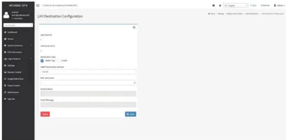
text_image
MEGARAC SPX MAGLIER M&T DESCRIPTION Host Online Quick Links Installboard Tanner Cycleres Inventory CPU Information Log & Requests Settings Remote Control Image-Substructure Power Control Main-Romaine Sign-Out LAN Destination Configuration LAN Channel: 1 LAN Description: 3 Description Type: SNMP Trap 8-mail SNMP Destination address: 6.0.0.0 MAC Standarder Email Subject Email Message Send to Save Home - Settings - Platform Name/Phone - LAN Destination - LAN Destination ConfigurationLAN Channel: Displays LAN Channel Number for the selected slot (read-only).
LAN Destination: Displays ID for setting Destination Selector of Alert Policy (read-only).
Destination Type: Destination type can be either an SNMP Trap or an E-mail alert. For E-mail alerts, the four fields - SNMP Destination Address, BMC User Name, Email subject and Email message needs to be filled. For SNMP Trap, only the SNMP Destination Address has to be filled.
SNMP Destination Address: If Destination type is SNMP Trap, then enter the IP address of the system that will receive the alert. Destination address will support the following:
- IPv4 address format.
- IPv6 address format.
BMC User Name: If Destination type is Email Alert, then choose the user to whom the email alert has to be sent. Email address for the user has to be configured under Settings > User Management.
Email Subject & Email Message: These fields must be configured if email alert is chosen as destination type. An email will be sent to the configured email address of the user in case of any severity events with a subject specified in subject field and will contain the message field's content as the email body. These fields are not applicable for 'AMI-Format' email users.

Note: Email address for the user should be configured under Settings > User Management.
Save: Saves a new entry to the device.
Delete: Deletes the selected configured LAN Destination.
Procedure
- In the LAN Destinations page, choose the number of slots to be configured. This should be the same number of slot that you have selected in the Alert Policies - Destination Selector field. That is if you have chosen the Destination Selector as 4 in the Alert Policies page of Alert Policies tab, then you have to configure the 4th slot of LAN Destination page.
-
Select the slot and click on the empty slot. This opens the LAN Destination entry.
-
In the LAN Channel Number field, the LAN Channel Number for the selected slot is displayed and this is a read only field.
- In the LAN Destination field, the destination for the newly configured entry is displayed and this is a read only field.
- In the Destination Type field, select the one of the types.
- In the SNMP Destination Address field, enter the destination address.
- If the destination type is Email alert, select the BMC User Name from the list of users.

Note: E-mail address should be configured under Settings > User Management.
- In the Email Subject field, enter the subject.
-
In the Email Message field, enter the message.
-
Click Save to save the new LAN destination and return to LAN destination list.
- Click Delete to delete a configuration.
- Click Send Test Alert to send sample alert to configured destination.

Note: Test alert can be sent only with enabled SMTP configuration. SMTP support can be enabled under Settings > SMTP Settings.
2-6-11 Services
This page displays the basic information about services running in the BMC. Only Administrator can modify the service.
To open Services page, click Settings > Services from the menu bar. A sample screenshot of Services page is shown below.

text_image
MEGARAC SP-X 12.01.38 A/PS 2021/NECKO-FC Hot Online Quick Online... Dashboard Server Synbase Inventory File Information Logic & Resources Settings Remode Control Intelligent Audioactus Power Control Maintenance sign out Services Service Status Interfaces Han Secure Port Secure Port Timeout Maximum Sessions web Active bonell 80 441 3859 20 knots Active bonell 7478 7642 3859 2 cell-media Active bonell 5139 5114 N/A 3 NDA-vesella Active bonell 5113 5117 N/A 3 zsh Active N/A N/A 23 690 N/A = ✓ = ✓ = ✓ = ✓ = ✓ = ✓ = ✓The fields in the Services page are explained below.
Services: Displays service name of the selected slot (read-only).
Status: Displays the current status of the service, either active or inactive state.
Interfaces: It shows the interface in which service is running.
Nonsecure Port: This port is used to configure non secure port number for the service.
- Web default port is 80.
• KVM default port is 7578.
• CD Media default port is 5120.
• HD Media default port is 5123.

Note: SSH service will not support non secure port. If single port feature is enabled, M, CD Media, and HD Media ports cannot be edited. Port value ranges in 1 to 65535.
Secure Port: This port is used to configure secure port number for the service.
- Web default port is 443.
• KVM default port is 7582.
• CD Media default port is 5124.
• HD Media default port is 5127. - SSH default port is 22.

Note: Telnet Port 80 is blocked for TCP/UDP protocols.
value ranges from 1 to 65535.
Port listening status on various feature settings:
| Single port enabled | Single port disabled | Only KVM encryption enabled | Only Media encryption enabled | Both KVM and Media encryption enabled | |
| Adviser (video server) | 7578 (LP) | 7578 (LP) 7578 (EO) | 7578 (LP) 7578 (EO) | 7578(LP) 7578 (EO) | 7578(LP) 7582 (EO) |
| Cdserver 5120 | (LP) | 5120 (LP) 5120 (EO) | 5120 (LP) 5120 (EO) | 5120 (LP) 5124 (EO) | 5120 (LP) 5124 (EO) |
| Hdserver 5123 | (LP) | 5123 (LP) 5123 (EO) | 5123 (LP) 5123 (EO) | 5123 (LP) 5127 (EO) | 5123 (LP) 5127 (EO) |

Note: LP - Loopback, EO - Exposed Outside.
The adviser will always be listening to loopback as well as kvm configured interface as mentioned in the above table. So that the H5Viewer client can connect to the video server.
The media servers will be listening to loopback as well as configured interface as mentioned in the above table. So that the lmedia/rmedia and H5Viewer/JViewer client can connect to the media servers.
Timeout: Displays the session timeout value of the service. Users can configure the session timeout value.

Note: Web timeout value ranges from 300 to 1800 seconds.
KVM timeout value ranges from 300 to 1800 seconds.
Web timeout value can be ignored if there is any ongoing KVM session.
SSH timeout value ranges from 60 to 1800 seconds.
Maximum Sessions: Displays the maximum number of allowed sessions for the service.
Save: Saves the configuration.
Service Sessions
The Service Sessions page is used to view the current active sessions for the service.
Procedure to open Service Sessions
- Click the View icon to view the details about the active sessions for the service.

text_image
MEGARAC SP-X 12.04.08 AVERAGE SERVICES &C Organ Online Quick Service Outperform Server Systems Inventory File Information Logic & Projects Settings Remote Control Intelligent Monitoring Power Control Maintenance Sign out Services Service 0 Status 0 interfaces 0 Ham Secure Part 0 Security Part 0 Tavout 0 Modemnt Solutions 0 web Active serverB 80 441 3606 20 link Active loadB 5178 7042 5608 2 cell antennas Active loadB 5129 5124 NA 3 cell assets Active loadB 5110 5117 NA 3 cell Active N/A NA 23 690 NA = ✓ ✓ ✓ ✓ ✓ ✓ ✓ ✓ ✓- This opens the Service Session screen (for example - Web service sessions) as shown in the screenshot below.
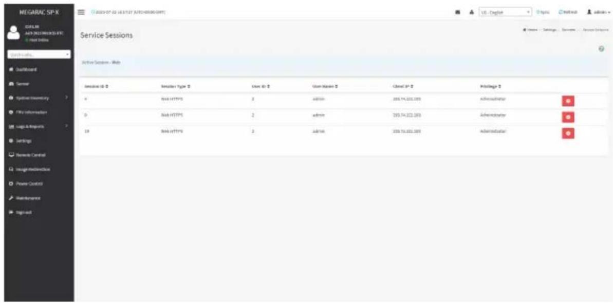
text_image
MEGARAC SP-X 12.04.08 A#P 2023/RESEARCH-SPX + Host Online Quick access... Dead/Burkard Server Synnex Inventory File Information Logic & Resources Settings Network Control Image Mechanical Power Control Maintenance Single-mail Service Sessions Active Session - Web Server ID: 0 Server Type: 0 User ID: 0 User Name: 0 Closal SP: 0 Privilege: 0 0 Web HTTPS: 2 admin: 209.74.201.003 Administrator 0 Web HTTPS: 2 admin: 209.74.201.003 Administrator SP Web HTTPS: 2 admin: 209.74.201.003 AdministratorSession ID: Displays the ID of the active sessions.
Session Type: Displays the type of the active sessions.
User ID: Displays the ID of the user.
User Name: Displays the name of the user.
Client IP: Displays the IP addresses that are already configured for the active sessions.
Privilege: Displays the access privilege of the user.
Procedure to modify the existing services
- Select a slot and click Edit icon to modify the configuration of the service.

Note: Whenever the configuration is modified, the service will be restarted automatically. has to close the existing opened session for the service if needed.

text_image
MEGARAC SP-X ELEUR AUY 2021 MEGARAC SP-X Host Online Quick Links... Dashboard Server Systems Inventory File Information Logic & Resources Settings Benedo Central Usage Media/Disk Power Control Maintenance Sign out Services Service Status Interfaces Han Secure Port Secure Port Tireout Management Services web Active bone/8 80 441 3800 20 loads Active bone/8 7978 7582 3800 2 cell-media Active bone/8 5129 5114 NA 3 Net-vesenda Active bone/8 5113 5117 NA 2 zds Active N/A N/A 23 600 N/A Home Settings Tools OK ✓- This opens the Service Configuration screen as shown in the screenshot below.
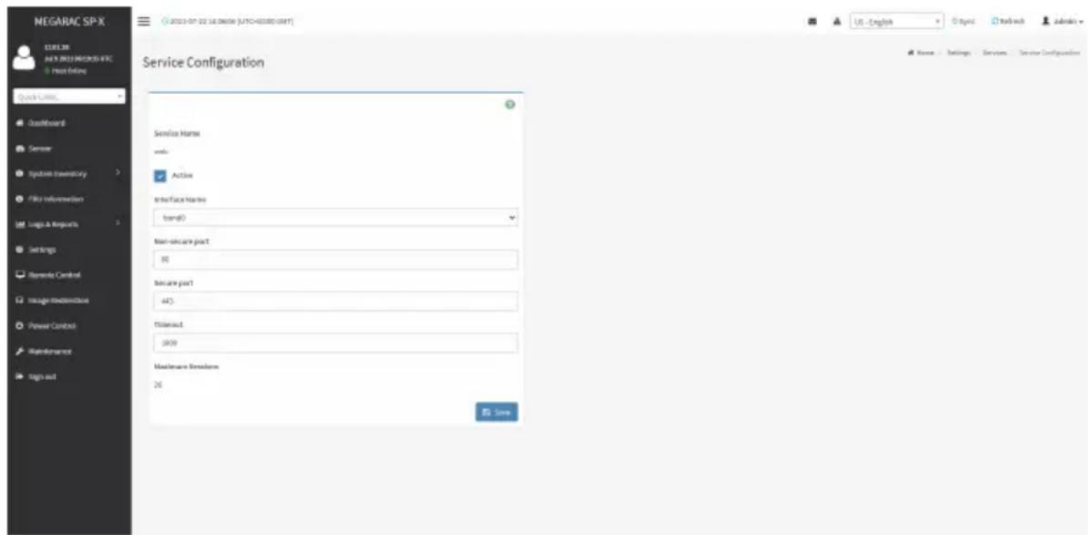
text_image
NEGARAC SP-X ELEL3R AUY 2013 PRODOS-IFC Host Online Quick Limits... Outperform Sensor System Inventory File Information Logs & Programs Settings Remode Control Storage/Modestock Power Control Maintenance Sign out Service Configuration Service Name: Add: Active Interface Name: band0 Non-secure part: 88 Secure part: 445 Threshold: 2009 Maintenance Residors: 26 Save Name: Settings Services Service Configuration- The Service Name filed is read-only.
- Check the Active check box to activate the service.

Note: Interfaces, Non-secure port, Secure port, Time out and Maximum Sessions will not give unless the current state is active.
- Select an available interface in the Interface Name field.
- Enter the Non-secure Port Number in the Non-secure Port field.
-
Enter the Secure Port Number in the Secure Port field.
-
Enter the timeout value in the Timeout field.
Note: The values in the Maximum Sessions field cannot be modified.

- Click Save to save all changes you have made.
2-6-12 SMTP Settings
Simple Mail Transfer Protocol (SMTP) is an Internet standard for electronic mail (e-mail) transmission across Internet Protocol (IP) networks.
Using MegaRAC GUI, you can configure the SMTP settings of the device.
To open SMTP Settings page, click Settings > SMTP Settings from the menu bar. A sample screenshot of SMTP Settings page is shown below.
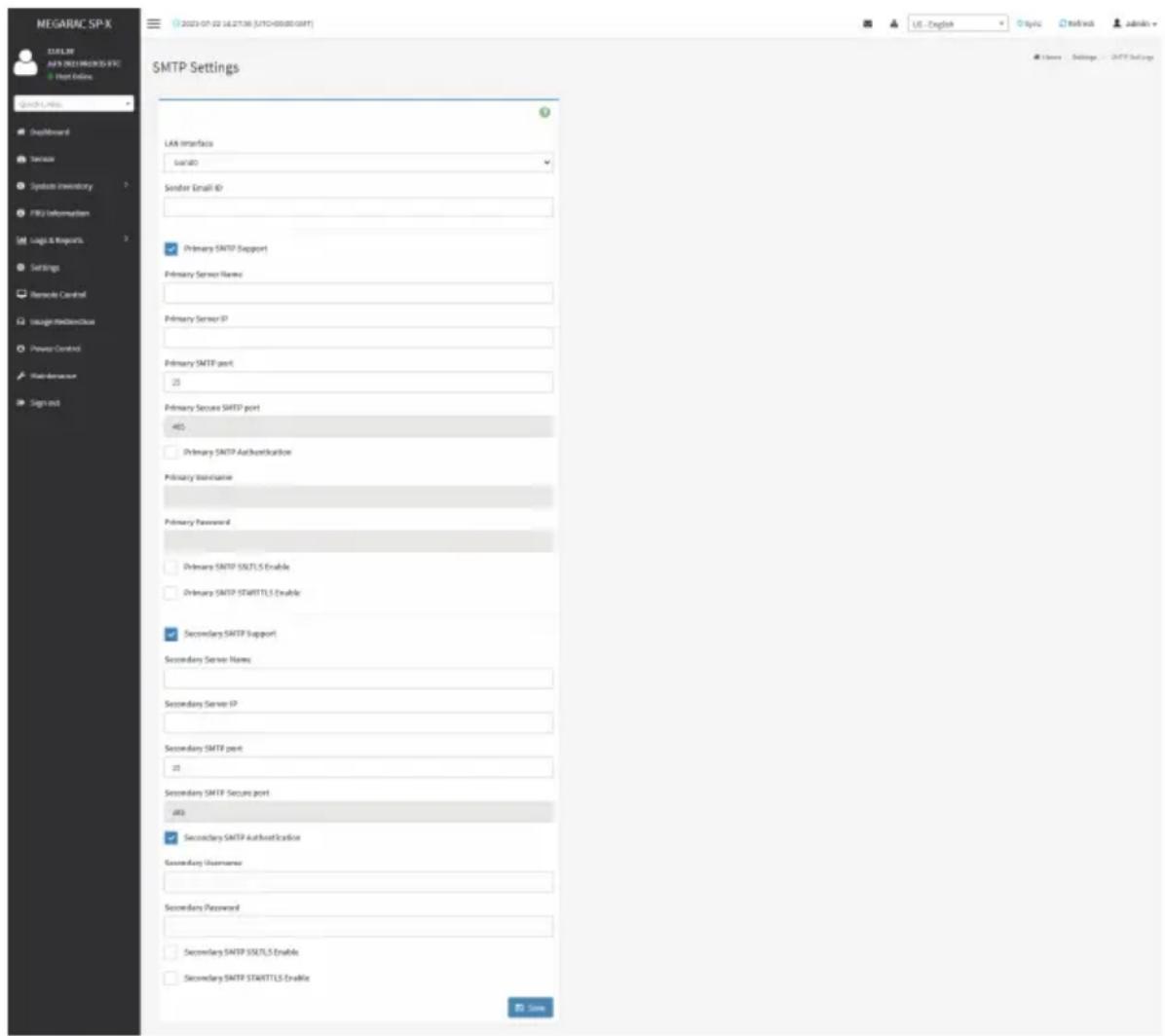
text_image
MEGARAC SP-X MELK AFYX 2001/2003/SPX Host Online Quick Links DropReward Service System Inventory FBS Information Logic & Requests Settings Remarks Control Usage Mechanical Power Control Web-Demware Sign out SMTP Settings LAR Interface SARISO Sender Email ID Primary SMTP Support Primary Server Name Primary Server IP Primary SMTP port: 25 Primary Secure SMTP port: 465 Primary SMTP Authentication Primary Maintenance Primary Password Primary SMTP SSLTLS Enable Primary SMTP STARTTLS Enable Secondary SMTP Support Secondary Server Name: Secondary Server IP Secondary SMTP port: 25 Secondary SMTP Secure port: 465 Secondary SMTP Authentication Secondary UserName: Secondary Password: Secondary SMTP SSLTLS Enable Secondary SMTP STARTTLS Enable USENThe fields in the SMTP Settings page are explained below.
LAN Interface: Displays the list of LAN channels available.
Sender Email ID: A valid 'Sender Address' to indicate the BMC, whenever e-mail is sent.
Primary SMTP Support: Enables/Disables SMTP support for the BMC.
Primary Server Name: The 'Machine Name' of the BMC, from where the e-mail is sent.

Note: Machine Name is a string of maximum 25 alpha-numeric characters.
Space, special characters are not allowed.
Primary Server IP: The IP address of the SMTP Server. It is a mandatory field.

Note: IP Address made of 4 numbers separated by dots as in "xxx.xxx.xxx.xxx".
Each Number ranges from 0 to 255.
First Number must not be 0.
Supports IPv4 Address format and IPv6 Address format.
Primary SMTP Port: Specifies the SMTP Normal Port.

Note: Default Port is 25, and the Port value ranges from 1 to 65535.
Primary Secure SMTP Port: Specifies the SMTP Secure Port.

Note: Default Port is 25, and the Port value ranges from 1 to 65535.
Primary SMTP Authentication: Enables/Disables SMTP Authentication.

Note: SMTP Server Authentication Types supported are:
- CRAM-MD5
- LOGIN
- PLAIN
If the SMTP server does not support any one of the above authentication types, the user will get an error message stating "Authentication type is not supported by SMTP Server."
Primary Username: Enter username to access SMTP Accounts.

Note: User Name can be of length 4 to 64 alpha-numeric characters, dot(.), dash(-), and underline(_) .
It must start with an alphabet.
Other special characters are not allowed.
Primary Password: Enter password for the SMTP User Account.

Note: Password must be at least 4 characters long.
Blank space is not allowed.
This field will not allow more than 64 characters.
Primary SMTP SSLTLS Enable: Enables SSLTLS support for the SMTP Client.
Primary SMTP STARTTLS Enable: Enables STARTTLS support for the SMTP Client.
- Upload SMTP CA Certificate File: File that contains the certificate of the trusted CA certs. CACERT key file should be of pem type,LOGIN
- Upload SMTP Certificate File: Client certificate filename. CERT key file should be of pem type.
- Upload SMTP Private Key: Client private key filename. SMTP key file should be of pem type.

Note: To enable STARTTLS support, the respective SMTP support option should be enabled.
Secondary SMTP Support: It lists the Secondary SMTP Server configuration. It is an optional field. If the Primary SMTP server is not working fine, then it uses Secondary SMTP Server configuration.

Note: Options of Secondary SMTP Support are same as Primary SMTP Support.
Save: Saves the new SMTP server configuration.
Procedure
- Select the LAN Interface from the drop-down list.
- Enter the Sender Email ID in the specified field.
- Check Primary SMTP Support option to enable SMTP support for the BMC.
- Enter the Machine Name of the SMTP Server in the Primary Server Name.

Note: Machine Name is a string of maximum 25 alpha-numeric characters.
Spaces and special characters are not allowed.
- Enter IP address of the SMTP Server in the Primary Server IP field. It is a mandatory field.
- Enter the Primary SMTP Port in the specified field.
- Enter the Primary Secure SMTP Port in the specified field.
- Check to enable Primary SMTP Authentication if you want to authenticate SMTP Server.
- Enter your Primary Username and Primary Password in the respective fields.
- Enable the check box Primary SMTP SSLTLS Enable to send data through secure Port.

Note: If this option is selected, STARTTLS option and Normal Port will be hidden.
- Check the Secondary SMTP Support option to enable Secondary SMTP support for the BMC.
- Enter the Secondary Server Name, Secondary Server IP, Secondary SMTP Port and Secondary SMTP Secure Port in the specified fields.
- Check to enable Secondary SMTP Server Authentication if you want to authenticate SMTP Server.
- Enter your Secondary Username and Password in the respective fields.
- Check to enable Secondary SMTP SSLTLS to send data through secure Port.

Note: If this option is selected, STARTTLS option and Normal Port will be hidden.
- Click Save to save the entered details.
2-6-13 SSL Settings
The Secure Socket Layer protocol was created by Netscape to ensure secure transactions between web servers and browsers. The protocol uses a third party, a Certificate Authority (CA), to identify one end or both end of the transactions.
Using MegaRAC GUI, configure SSL certificate into the BMC. Using this, the device can be accessed in a secured mode.
To open the SSL Certificate Configuration page, click Settings > SSL Settings from the menu bar. There are three tabs in this page.

text_image
NEGARAC SP-X 13.01.30 44.5.2001/2006/07/06 View Offline SOSING PROSL Default Board Server Symbol inventory File information Logo & Impacts Settings Networks Control Image-Reference Power Controls Maintenance High-out SSL Settings New SSL certificate Deviate SSL certificate Quick SSL certificateThe fields in the SSL Settings page are explained below.
View SSL Certificate: Displays the uploaded SSL certificate's information.
Generate SSL Certificate: Generates the SSL certificate based on configuration details.
Upload SSL Certificate: Uploads SSL certificate in readable format.
View SSL Certificate
A sample screenshot of View SSL Certificate page is shown below.

text_image
MEGARAC SP-X CERL.BK NEW DREAMERS VFC View Info View SSL Certificate Current Certificate Information Certificate Reviewer ) Build Number S1CP100002(4)04935(0)0837(4)0479(0)04932 logitech Algorithm on L200000000000000000000000000000000000000000000000000000000000000000000 Public Key (2014-12) Issuer Conference Name (CN) engarac.com Issuer Organization (U) American Engineering Center (USA) LLC (USA) Issuer Organization (UK) (UK) Service Processors Issuer City on Locality (C) Services Issuer State or Ministry (SF) Services Issuer Country (C) US Issuer Text Address support@lemc.com Mail Form AU 13 18:35:27 2011 Email Mail Link AU 13 18:35:27 2011 Email Issued for Candidates Market (EX) imagarc.com Issued for organization (I) American Government International LLC (AHC) Issued for organization staff (IIT) Service Providers Issued for City on Locality (C) Incorporated Issued for Market or Preference (IT) Georgia Issued for Country (C) US Issued for Email Address support@lemc.comThe fields in the View SSL Certificate page are explained below.
Current Certificate Information: This section displays the basic information about the uploaded SSL certificate. It displays the following fields:
- Certificate Version
- Serial Number
- Signature Algorithm
• Public Key - Issuer Common Name (CN)
- Issuer Organization (O)
- Issuer Organization Unit (OU)
- Issuer City or Locality (L)
- Issuer State or Province (ST)
- Issuer Country (C)
- Issuer E-mail Address
-
Valid From
-
Valid Till
- Issued to Common Name (CN)
- Issued to Organization (O)
- Issued to Organization Unit (OU)
- Issued to City or Locality (L)
- Issued to State of Province (ST)
- Issued to Country (C)
- Issued to Email Address
Generate SSL Certificate
A sample screenshot of Generate SSL Certificate page is shown below.

text_image
MEGARAC SP-X C:\SEL.BK\ALL\MEGARAC SP-X + Plus Default Generate SSL Certificate Customer License (C) Organizers (R) Organizers Unit (U) City of Locality (C) State or Privatock (S) Covality (C) Address Address Markit No. In-Print Buy Length (Off) bits USEThe fields in the Generate SSL Certificate page are explained below.
Common Name (CN): Common name for which certificate is to be generated.
• Maximum length of 64 characters.
- It is a string of alpha-numeric characters.
- Special characters '#' and '\$' are not allowed.
Organization (O): Organization name for which the certificate is to be generated.
• Maximum length of 64 characters.
- It is a string of alpha-numeric characters.
- Special characters '#' and '\$' are not allowed.
Organization Unit (OU): Over all organization section unit name for which certificate is to be generated.
• Maximum length of 64 characters.
- It is a string of alpha-numeric characters.
- Special characters '#' and '\$' are not allowed.
City or Locality (L): City or Locality of the organization (mandatory).
• Maximum length of 128 characters.
- It is a string of alpha-numeric characters.
- Special characters '#' and '\$' are not allowed.
State or Province (ST): State or Province of the organization (mandatory).
• Maximum length of 128 characters.
- It is a string of alpha-numeric characters.
- Special characters '#' and '\$' are not allowed.
Country (C): Country code of the organization (mandatory).
- Only two characters are allowed.
- Special characters are not allowed.
Email Address: E-mail Address of the organization (mandatory).
Valid for: Validity of the certificate.
• Value ranges from 1 to 3650 days.
Key Length: The key length bit value of the certificate.
Save: Generates the new SSL certificate.

Note: HTTPS service will get restarted, to use the newly generated SSL certificate.
Upload SSL Certificate
A sample screenshot of Upload SSL Certificate page is shown below.
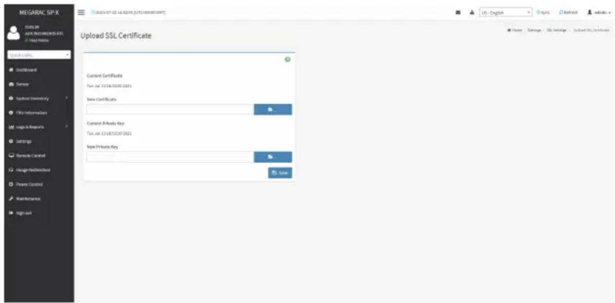
text_image
MEGARAC SP-X NEW YORK New York 2021 NEW YORK Quick Online... Upload Board Server Hyperlink Inventory File Information Logic & Resources Settings Remote Control Intangible Data Power Control Maintenance Sign out Upload SSL Certificate Current Certificate Tue Jul 13 18:52:00 2021 New Certificate Current Private Key Tue Jul 13 18:52:00 2021 New Private Key SaveThe fields in the Upload SSL Certificate page are explained below.
Current Certificate: Current certificate and uploaded date/time will be displayed (read-only).
New Certificate: Browse the new certificate file. The certificate file should be of pem type.
Current Private Key: Current Private key information will be displayed (read-only).
New Private Key: Browse the new private key. The private key file should be of pem type.
Save: Uploads the SSL certificate and privacy key into the BMC.

Note: After successful upload, HTTPS service will restart to use the newly uploaded SSL certificate.
Procedure
- Click the Upload SSL Certificate tab, browse the New Certificate and New Private key.
- Click Save to upload the new certificate and private key.
-
In Generate SSL Certificate, enter the following details in the respective fields:
-
The Common Name for which the certificate is to be generated.
- The Organization for which the certificate is to be generated.
-
The Organization Unit name for which certificate to be generated.
• The City or Locality of the organization
• The State or Province of the organization
• The Country of the organization
• The Email address of the organization.
• The number of days the certificate will be valid in the Valid For field. -
Choose the Key Length bit value of the certificate
- Click Save to generate the certificate.
- Click View SSL Certificate tab to view the uploaded SSL certificate in user readable format.

Note: Once you Upload/Generate the certificates, only HTTPS service will get restarted. I can now access your Web securely using the following format in your IP Address
field from your Internet browser: https://
https://192.168.030
Please note the after
2-6-14 System Firewall
In MegaRAC GUI, the System Firewall page allows you to configure the firewall settings. The firewall rule can be set for an IP or range of IP Addresses or Port numbers. To view this page, you must at least be an operator. Only administrators can add or delete a firewall.
To open System Firewall page, click Settings > System Firewall from the menu bar.

text_image
MEGARAC SP-X 12.01.38 AVS NEW MEGARAC SPX Hot Online Quick Links... Dashboard Server System Inventory File Information Logic & Reports Settings Remode Control Intelligent Broadcast Power Control Maintenance Sign out System Firewall General Firewall Settings IP Additional Firewall Rules Port Firewall Rules USE - English Topic Refresh Admins Name Settings Open/ForwardGeneral Firewall Settings
Click General Firewall Settings page. A sample screenshot of General Firewall Settings page is shown below.

text_image
NEGARAC SP-X BLUE Server AVEN 2013 PROWEED EPC File Online Quick Lines... Dustboard Sensor Instruments inventory File Information Logis & Reporters Settings Remote Control Usage Devices Power Control Maintenance Tags out General Firewall Settings + + + + + + + + + + + + + + + + + + + + + + + + + + + + + + + + + + + + + + + + + + + + + + + + + + + + + + + + + + + + + + + + + + + + + + + + + + + + + + + + + + + + + + + + + + + + + + + + + + + + - - - - - - - - - - - - - - - - - - - - - - - - - - - - - - - - - - - - - - - - - - - - - - - - - - - - - - - - - - - - - - - - - - - - - - - - - - - - - - - - - - - - - - - - - - - - - - - - - - - - -The fields in the Firewall Settings page are explained below.
Existing Firewall Settings
Click General Firewall Settings > Existing Firewall Settings icon. A blank page will be opened if you did not add anything in Add Firewall Settings. If any settings are added, then the added rule will be listed in Existing Firewall Settings page. A sample screenshot of Existing Firewall Settings page is shown below.

text_image
MEGARAC SP-X 13.91.33 Aug 12 2015 04:21:01 UTC © New Office Quick Links... Dashboard Sensor System Inventory FRII Information Logs & Reports Settings Remote Control Image Redirection Power Control Maintenance Sign out Existing Firewall Settings Block All: IPv4 Timeout: Enabled Points Set Aug 22 2021 17:16:00 To: Set Aug 21 2021 21:23:00 US - English Sync Refresh admin - Home - Settings - Firewall - General Firewall Settings - Existing Firewall SettingsThe Existing Firewall Settings page allows you to remove any particular Existing Firewall Settings.
Procedures
- Select the Existing Firewall Settings you want to remove.
- Click on Delete to remove the selected Existing Firewall Settings.

text_image
MEGARAC SP-X 13.81.93 Aug 12 2021 06 21:41 UTC © New Office Quick Links. Dashboard Sensor System Inventory FRU Information Log & Reports Settings Remote Control Image Redirection Power Control Maintenance Sign out Existing Firewall Settings Block All IPv4 Phosh AB Timeout Start Date&Time Sat Aug 21 2021 17:19:00 End Date&Time Sat Aug 21 2021 21:20:00 Delete US - English Sync Refresh admin Name - Settings - Firewall - General Firewall Settings - Existing Firewall Settings - Funding Firewall SettingsAdd Firewall Settings
Click General Firewall Settings > Add Firewall Settings. This opens the Add Firewall Settings page as shown below.
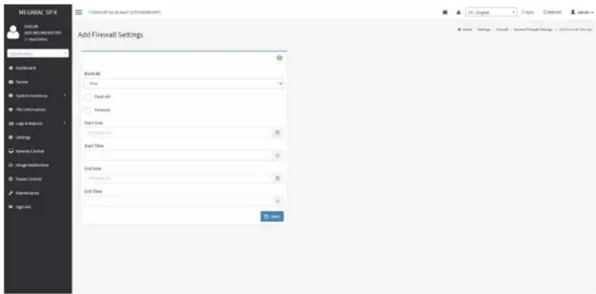
text_image
NEGAURC SP.X ADD NEW BREAKS VEN Add Existing Add Firewall Settings Block All Push Flush All Networks Start Subs Enter All Subs Start Time Grid Date Enter Subs Grid Time SaveProcedures
- Select Block All to block all the incoming IP's and Port's.
- Select Flush All to flush all the system firewall rules.
- Select Timeout to enable or disable firewall rules with timeout.
- Enter Start Date to start the respective firewall rule effect from this date.
- Enter Start Time to start the respective firewall rule effect from this time.
- Enter End Date to end the respective firewall rule effect from this date.
- Enter End Time to end the respective firewall rule effect from this time.
- Click Save to save the changes made.
IP Address Firewall Rules
Click IP Firewall Rules page. A sample screenshot of IP Firewall Rules page is shown below.

text_image
NEGARAC SP-X C:\EEL\MAY 2021 NEW築籤\IFC Host Online Quick Links... Dustboard Sensor Symbols Inventory File Information Logs & Reposets Settings Remode Control Image Manufacturing Power Control Maintenance Sign out IP Firewall Rules Existing IP Rules Add/Remove IP Rule US - English Topic Refresh Admins Home Settings Forward IP Firewall RulesThe fields in the IP Address Firewall page are explained below.
Existing IP Rules
To view Existing IP Rules, click Settings > System Firewall > IP Address Firewall Rules > Existing IP Rules. A blank page will be opened if you did not add anything in Add IP Rule. If any rule is added, then the added rule will be listed in Existing IP Rules page.
A sample screenshot of Existing IP Rules page is shown below.

text_image
MEGARAC SP-X 13.01.03 Aug 12 2021 08:20:01 UTC © Host Office Quick Links... Dashboard Sensor System Inventory FISU Information Logs & Reports Settings Remote Control Image Redirection Power Control Maintenance Sign out 2021-04-02 22:58:00 (UTC+80:00 GMT) US - English Sync Refresh admin - Existing IP Rules IP / IP Range: 10.1.T,100 - 10.1.T,200 Rule: Allure Timeout: Enabled From: Saturday, August 21st 2021, 9:23:00 am. To: Saturday, August 21st 2021, 2:23:00 pmThe Existing IP Rules page allows you to remove any particular Existing IP Rules.
Procedure
- Select the Existing IP Rules you want to remove.
- Click on Delete to remove the selected Existing IP Rules.
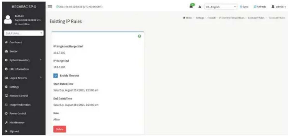
text_image
MEGARAC SP-X 13.06.33 Aug 02 2021 18:21:00 UTC About Office Quick Links... Dashboard Sensor System Inventory FRU Information Logs & Reports Settings Remote Control Image Redirection Power Control Maintenance Sign out 2021-04-03 12:58:31 (UTC=00.06 GMT) US - English Sync Refresh admin- Existing IP Rules IP Single (or) Range Start 10.1.7.100 IP Range End 10.1.7.200 Enable Timeout Start Dates&Time Saturday, August 21st 2021, 9:23:00 am End Dates&Time Saturday, August 21st 2021, 2:23:00 am Rule Allion DeleteIP Single (or) Range Start: Shows the configured Port Address or Range of Ports.
IP Range End: Shows the configured Port Address or Range of Ports.
Enable Timeout: Enables/Disables Timeout.
Start Date: The respective firewall rule effect will start from this date.
Start Time: The respective firewall rule effect will start from this time.
End Date: The respective firewall rule effect will end from this date.
End Time: The respective firewall rule effect will end from this time.
Rule: Indicates the current setting of the listed Port or Range of Port rules (Allow or Block) status.
Delete: Deletes the selected slot.
Add IP Rule
To add a new IP rule, click Settings > System Firewall > IP Address Firewall Rules > Add New IP Rule. If any rule is added, then the added rule will be listed in Existing IP Rules page.
A sample screenshot of Add IP Rule page is shown below.
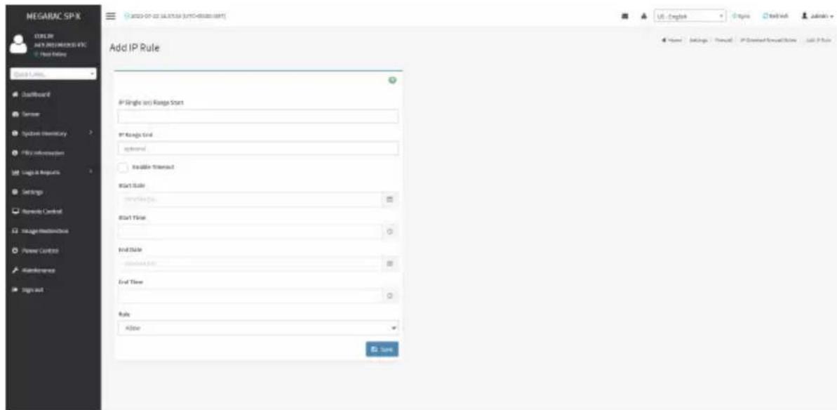
text_image
NEGARAC SPX C:\Users\NAY PREMERSIONS EPC Start Ending Quick Links DefaultReport Sensor System Inventory My Information Logic & Requests Settings Remarks Control Image Hardware Power Control Maintenance Sign out Add IP Rule IP Single (or) Range Start IP Range End systemed Available Threshold Start Rule: Start Date: End Date: End Time: Rule: Alose Save Name Settings Format IP Created Software Tools Help IP RuleProcedure
- In the Add IP Rule page, enter the IP address and a range of IP addresses in the IP Single or IP Range Start field.

Note: IP Address will support IPv4 Address format only:
TPv4 Address made of 4 numbers separated by dots as in xxx.xxx.xxx.xxx.
Each number ranges from 0 to 255.
First number must not be 0.
- Enter IP range end value in the IP Range End field.
- Enable Timeout to enable firewall rules with timeout.
- Enter Start Date to start the respective firewall rule effect from this date.
- Enter Start Time to start the respective firewall rule effect from this time.
- Enter End Date to end the respective firewall rule effect from this date.
- Enter End Time to end the respective firewall rule effect from this time.

Note: The date and time should be in the YYYY/MM/DD and hh-mm format respectively.
- Determine the rule to block or accept.
- Click Save to save the changes made.
Port Firewall Rules
Click Port Firewall Rules page. A sample screenshot of Port Firewall Rules page is shown below.

text_image
MEGARAC SP-X NEW YEAR NEW ITEMS Import Online Quick Links... Dashboard Server System Inventory File Information Logic & Resources Settings Semiconductor Control Intelligent BroadcastBox Power Control Maintenance Tags out Port Firewall Rules Building Port Rules Add New Rule Rule Home Settings - Forward - Port Firewall RulesExisting Port Rules
To view Existing Port Rules, click Settings > System Firewall > Port Firewall Rules > Existing Port Rules. A blank page will be opened if you did not add anything in Add New Port Rule. If any rule is added, then the added rule will be listed in Existing Port Rules page.
A sample screenshot of Existing Port Rules is shown below.
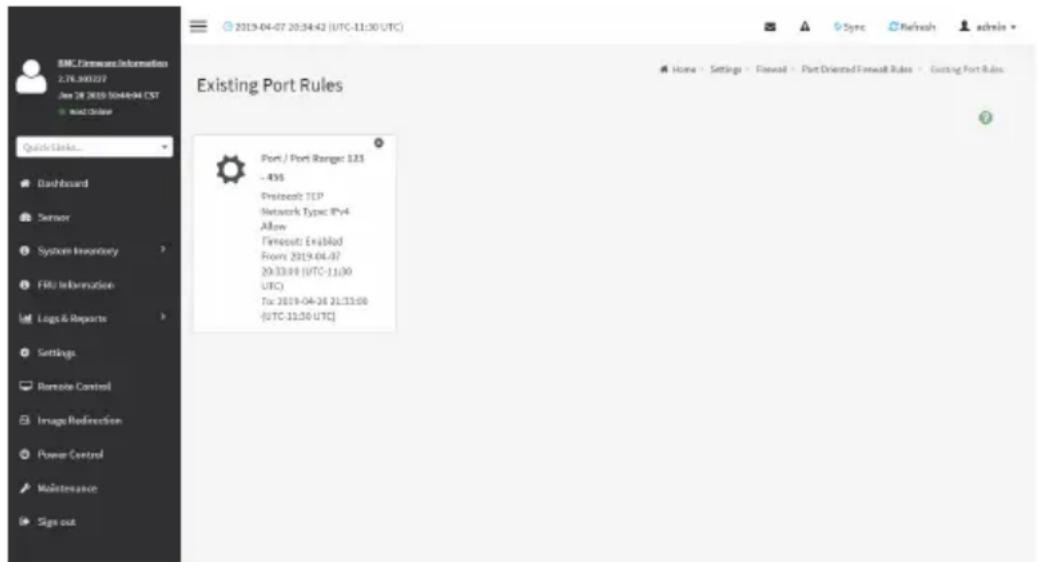
text_image
BMC Firmware Information 2.78.300227 Jan 28 2019 10:44:04 EST + Quick Order Quick Links... Dashboard Sensor System Inventory FRU Information Logs & Reports Settings Remote Control Image Redirection Power Control Maintenance Sign out 2019-04-07 20:34:42 (UTC-11:30 UTC) Existing Port Rules Port / Port Range: 123 - 476 Prentool: TCP Network Type: IPy4 Allow Firmout: Ex&lMad From: 2019-04-07 20:33:00 (UTC-11:00 UTC) To: 2019-04-26 21:33:00 (UTC-11:30 UTC)Procedure
- Select the Existing Port Rules you want to remove.
- Click on Delete to remove the selected Existing Port Rules.

text_image
BMC Firmware Information 2.76.300227 Jan 28 2015 10:48-04 CST Wind Drive Quick Links... Dashboard Sensor System Inventory FRU Information Logo & Reports Settings Remote Control Image Redirection Power Control Maintenance Sign out Existing Port Rules Port Single (or) Range Start 123 Port Range End 458 Protocol TCP Network Type IPyA Enable Timeout Start Date&Time 2019-04-07 20:33:00 (UTC-11:30 UTC) End Date&Time 2019-04-25 21:33:00 (UTC-11:30 UTC) Rule Allow DeleteThe fields in the Existing Port Rules page are explained below.
Port Single (or) Range Start: Configures the Port or Range of Port Addresses.
Port Range End: Configures the Port or Range of Port Addresses.
Protocol: This field specifies the protocols for the configured Port or Port Ranges.
Network Type: This field specifies the affected network type for the particular Port or Port
Ranges.
Enable Timeout: Enables/Disables firewall rules with timeout.
Start Date: The respective firewall rule effect will start from this time.
Start Time: The respective firewall rule will start from this time.
End Date: The respective firewall rule effect will end on this date.
End Time: The respective firewall rule will end at this time.
Rule: Indicates Allow or Block status.
Delete: Deletes the entry to the firewall rules list.
Add New Port Rule
To add a new port rule, click Settings > System Firewall > Port Firewall Rules > Add New
Port Rule. A sample screenshot of Add New Port Rule is shown below.

text_image
MEGARAC SP-X NEW NELL MINDS-INFO Host Online Quick Links... DeepWizard Service System Inventory FPU Information Logic & Resources Settings Services Control Usage Infrastructure Power Control Maintenance Sign out Add Port Rule Port Single (or) Range Start Port Range End optional Protocol: TCP Network Type: iOS Enable "Transport" Start Rule: engguanapp Start Title: End Date: engguanapp End Time: Rule: Allow: Home Settings Password Port Drivened Passoff Rules Make/Use RuleProcedure
- In the Port Single (or) Range Start field, enter the port number or a range of port addresses.

Note: Port value ranges from 1 to 65535.
80 is blocked for TCP/UDP protocols.
- Enter the end value in the Port Range End field.
- Select the Protocol to be either TCP or UDP or Bot.
- Select the Network Type. It may be IPv4 or IPv6 or Both.
- Check/uncheck Enable Timeout to enable/disable firewall rules with timeout.
- Enter Start Date to start the respective firewall rule effect from this date.
- Enter Start Time to start the respective firewall rule effect from this time.
- Enter End Date to end the respective firewall rule effect on this date.
- Enter End Time to end the respective firewall rule effect at this time.

Note: The time should be in the YYYY/MM/DD:hh-mm format.
- Select either Block or Allow in the Rule field.
- Click Save to save the changes made.
2-6-15 User Management
In MegaRAC GUI, the User Management page allows you to view the current list of user slots for the server. You can add a new user and modify or delete the existing users.
To open User Management page, click Settings > User Management from the menu bar. A sample screenshot of User Management page is shown below.
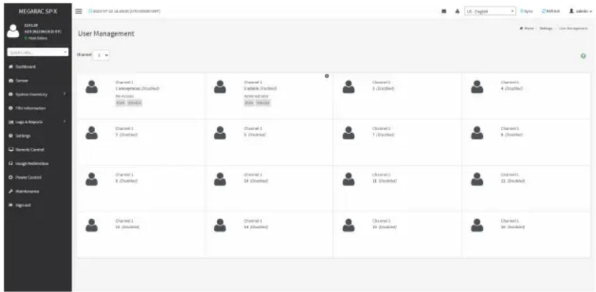
text_image
MEGARAC SP-X USER NEW BUSINESS EPIC Host Online Quick Links... Dashboard Sensor Systems Inventory File Information Logic & Repurchase Settings Bemers Control Usage Realdehyde Power Control Maintenance Sign out User Management Channel 1 1. Interpersonal (Disabled) No Acclose Pure, Unadded Channel 1 2. Adelta (Disabled) Administrator Post "PAGE" Channel 1 3. (Disabled) Channel 1 4. (Disabled) Channel 1 5. (Disabled) Channel 1 6. (Disabled) Channel 1 7. (Disabled) Channel 1 8. (Disabled) Channel 1 9. (Disabled) Channel 1 10. (Disabled) Channel 1 11. (Disabled) Channel 1 12. (Disabled) Channel 1 13. (Disabled) Channel 1 14. (Disabled) Channel 1 15. (Disabled) Channel 1 16. (Disabled) Channel 1 17. (Disabled) Channel 1 18. (Disabled) Channel 1 19. (Disabled) Channel 1 20. (Disabled) Channel 1 21. (Disabled) Channel 1 22. (Disabled) Channel 1 23. (Disabled) Channel 1 24. (Disabled) Channel 1 25. (Disabled) Channel 1 26. (Disabled) Channel 1 27. (Disabled) Channel 1 28. (Disabled) Channel 1 29. (Disabled) Channel 1 30. (Disabled) Channel 1 31. (Disabled) Channel 1 32. (Disabled) Channel 1 33. (Disabled) Channel 1 34. (Disabled) Channel 1 35. (Disabled) Channel 1 36. (Disabled) Channel 1 37. (Disabled) Channel 1 38. (Disabled) Channel 1 39. (Disabled) Channel 1 40. (Disabled) Channel 1 41. (Disabled) Channel 1 42. (Disabled) Channel 1 43. (Disabled) Channel 1 44. (Disabled) Channel 1 45. (Disabled) Channel 1 46. (Disabled) Channel 1 47. (Disabled) Channel 1 48. (Disabled) Channel 1 49. (Disabled) Channel 1 50. (Disabled) Channel 1 51. (Disabled) Channel 1 52. (Disabled) Channel 1 53. (Disabled) Channel 1 54. (Disabled) Channel 1 55. (Disabled) Channel 1 56. (Disabled) Channel 1 57. (Disabled) Channel 1 58. (Disabled) Channel 1 59. (Disabled) Channel 1 60. (Disabled) Channel 1 61. (Disabled) Channel 1 62. (Disabled) Channel 1 63. (Disabled) Channel 1 64. (Disabled) Channel 1 65. (Disabled) Channel 1 66. (Disabled) Channel 1 67. (Disabled) Channel 1 68. (Disabled) Channel 1 69. (Disabled) Channel 1 70. (Disabled) Channel 1 71. (Disabled) Channel 1 72. (Disabled) Channel 1 73. (Disabled) Channel 1 74. (Disabled) Channel 1 75. (Disabled) Channel 1 76. (Disabled) Channel 1 77. (Disabled) Channel 1 78. (Disabled) Channel 1 79. (Disabled) Channel 1 80. (Disabled)The fields in the User Management page are explained below.

Note: The free slots are shown as "Disabled" in all columns for the slot.
User ID: Displays the ID number of the user.

Note: The list contains a maximum often users only.
User Name: Displays the name of the user.
User Access: Enables/Disables the access privilege of the user.
Network Privilege: Displays the network access privilege of the user.
SNMP Status: Displays if the SNMP status for the user is enabled or Disabled.
E-mail ID: Displays e-mail address of the user.
Add User: Adds a new user.
Delete User: Deletes an existing user.

text_image
MEGARAC SPX ASP.NET ASP.NET PROGRESSIVE VEC User Interface Check Links... Defaulted Session Updated Inventory USB Information Log & Request Settings Remote Central Image-Indemise Power Controls MultiResources Sign All User Management Configuration Userlisters amorphisms Change Password Password/Title IP By/User Password: Defaulted Packages 8 Enable User Access Enable Channel Access Channel 1 Channel 1 Privilege(Channel 1) Issue Privilege(Channel 2) Administrator XML Access VMData Access SMTP Access SMTP Access level SMTP Authentication Preferred SMTP Privacy Financial Email Former Add For Output Email ID: Existing SMTP Key Use shareable Upload SMTP Key Cancel Help Help Settings - User Management - User Management ConfigurationsProcedure
- To add a new user, select an empty slot on the User Management page. The User Management Configuration screen will appear,
- Enter user name in the Username field.

Note: User name is a string of 1 to 16 alpha-numeric characters.
It must start with an alphabetical character and it is case-sensitive.
Special characters '-'(hyphen), '-' (underscore), '@'(at sign) are allowed.
For 20 Bytes password, LAN session will not be established.
- Check Change Password if you want to change the password.
- Set Password Size for the new password.
- In the Password and Confirm Password fields, enter and confirm the password.

Note: Password should be the combination of alphabets, numbers, symbol and upper characters.
Blank space is not allowed.
This field will not allow more than 16/20 characters based on Password size field value.
This field will not allow the below mentioned characters.
The password should be a string, if you try to set password using "ipmitool user set password".
| Hex Char | |
| 00 NUL '\0' | |
| 01 SOH (start of heading) | |
| 02 STX (start of text) | |
| 03 ETX (end of text) | |
| 04 EOT (end of transmission.) | |
| 05 ENQ (enquiry) | |
| 06 ACK (acknowledge) | |
| 07 BEL '\a' (bell) | |
| 08 BS '\b' (backspace) | |
| 09 HT '\t' (horizontal lab) | |
| 0A LF '\n' (new Line) | |
| 0B VT '\v' (vertical tab) | |
| 0C FF '\f' (form feed) | |
| 0D CR '\r' (carriage ret) | |
| 0E SO (shift out) | |
| 0F SI (shift in) | |
| 10 DLE (data link escape) | |
| 11 DC1 (device control 1 ) | |
| 12 IDC2 (device control 2) | |
| 13 DG3 (device control 3) | |
| 14 DC4 (device control 4) | |
| 15 NAK (negative ack.) | |
| 16 SYN (synchronous idle) | |
| 17 ETB (end of trans. blk) | |
| 18 CAN (cancel) | |
| 19 EM (end of medium) | |
| 19 EM (end of medium) | |
| 1A SUB (substitute) | |
| 1B ESC (escape) | |
| 1C FS (file separator) | |
| 1D GS (group separator) | |
| 1E RS (record separator) | |
| 1F US (unit separator) | |
| 20 SPACE | |
| 7F DEL |
- Enable or disable the Enable User Access.
- Enable or disable the Enable Channel Access.

Note: Enabling channel access will assign the IPMI messaging privilege to user.
It is recommended that the IPMI messaging option should be enabled as well if user is created through IPMI.
- In the Privilege (Channel 1) and Privilege (Channel 2) fields, select a privilege level.
- Check KVM Access to assign the KVM privilege.
- Check VMedia Access assign the VMedia privilege.

Note: It is recommended that the privileges support to KVM and VMedia should be
provided only to the ADMIN user and shouldn't be provided to USER and OPERATOR privilege level users. The Admin user can provide the privilege support to USER and OPERATOR privilege level users at their own risk.
VMedia Privilege only restricts initiating / starting media redirection. If a device is already being redirected and attached to the host, then in host it will be visible as normal device. Hence, it will be accessible to all the KVM sessions, which includes 'KVM Privilege only' sessions as well.
- Check SNMP Access to enable SNMP access for the user.

Note: Password field is mandatory, if SNMP is enabled.
- Choose the SNMP Access level option for user from the SNMP Access level (SHA or MD5) drop-down list. Either it can be read-only or read-write.
- Choose the SNMP Authentication Protocol (SHA or MD5) to use for SNMP settings from the drop down list.

Note: Password field is mandatory, if Authentication protocol is changed.
- Choose the Encryption algorithm to use for SNMP settings from the SNMP Privacy Protocol drop-down list.
- In the Email ID field, enter the email ID of the user. If the user forgets the password, the new password will be mailed to the configured email address.

Note: SMTP Server must be configured to send emails.
Email Format: Two types of formats are available:
- AMI-Format: The subject of this mail format is 'Alert from (your Host name)'. The mail content shows sensor information, ex: Sensor type and Description.
-
Fixed-Subject Format: This format displays the message according to user's setting. You must set the subject and message for email alert.
-
The Existing SSH Key field displays information of an existing SSH key.
- In the Upload SSH Key field, click Browse and select the SSH key file.

Note: SSH key file should be of pub type.
- Click Save to save the new user and return to the users list.
If you need to modify the privilege or information of an existing user, select the user on the User Management page to open the User Management Configuration screen and modify the configurations accordingly.
2-6-16 Video Recording
The Video Recording consists of the following:
- Auto Video Settings
• Video Trigger Settings
• Video Remote Storage
• Pre-Event Video Recordings
-
SOL Settings
-
SOL Trigger Settings
• SOL Video Remote Storage - SOL Recorded Video
A sample screenshot of the Video Recording is given below.
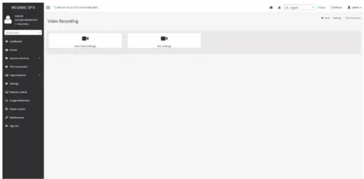
text_image
NEGARAC SP-X 12.08.30 JUL 2013 MEGROS-IFC Host Online Quick URL: Dustboard Server Integrated Inventory File Information Logic & ImageX Settings Remedy Control Usage Effectiveness Power Control Maintenance Sign out 2021-07-22 16:47:37 (JYTC-00:00:00:00) Video Recording Auto/Video Settings BOS Settings US - English Topic Mailtech Admins Home Settings Video RecordingA detailed description of the menu items are given below.
Auto Video Settings
The Auto Video Settings page allows you to configure the events that will trigger auto video recording function of the KVM server and view the current list of user slots for the server. You can add a new user and modify or delete the existing users.
This page is used to configure the events that will trigger auto video recording function of the KVM server.
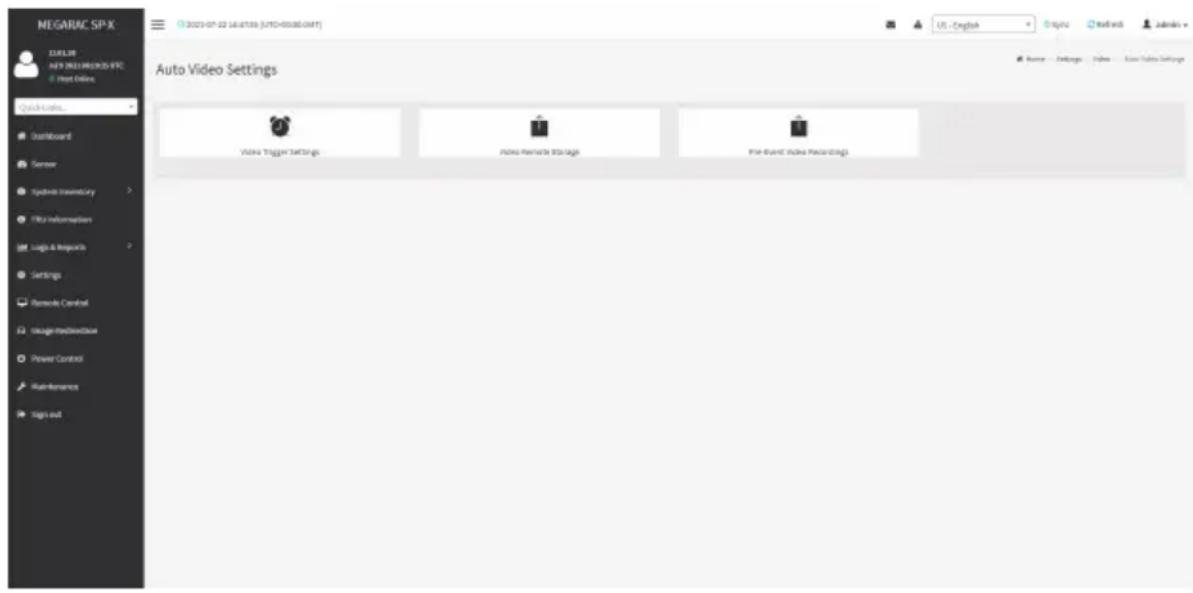
text_image
NEGARAC SP-X TITLE NEW NEELEMECKO-IFC Hot Online Quick Links... Dashboard Server Synthetic Inventory File Information Logic & Impacts Settings Remote Control Usage/Recordbox Power Control Maintenance Sign out 2021-07-22 16:47:59 (UHTD-00380.GMT) US - Engink Autol Supply Settings Video Trigger Settings Index Remote Storage Event Event Video PackingsTo triggers for Auto Video Recording, click Video Recording > Auto Video Settings > Video Trigger Settings from the menu bar. A sample screenshot of Video Trigger Settings page is shown below.

text_image
MEGARAC SP-X CULS 2023 NOGARAC SPX Use Online Quick Limits... Dust/Border Sensor System Inventory File Information Logic & Monopics Settings Remode Control Usage/Modematics Power Control Maintenance Sign out Video Trigger Settings Critical Events (Temperatures/Volages) Non-Critical Events (Temperatures/Volages) Non-Recoverable Events (Temperatures/Volages) Fan status changed Event Watching Theme Events Chassis Player On Events Chassis Player Off Events Chassis Reset Events LPC Reset Events State and Theme Event Plus instant Before Eventing USEVideo Trigger Settings
Event List: It shows the list of available events to be configured. The events are mentioned below.
• Critical Events (Temperature/Voltage)
• Non Critical Events (Temperature/Voltage)
• Non Recoverable Events (Temperature/Voltage)
• Fan state changed Events
- Watchdog Timer Events
- Chassis Power on Events
- Chassis Power off Events
- Chassis Reset Events
- LPC Reset Events
- Date and Time Event
• Pre-Event Video Recording
Save: Saves the current changes.
Procedure
- Check the events to be enabled.
- To set particular date and time event, check the option Date and Time Event.
a) Choose the month, day and year from the Date field
b) Enter/Choose the time in hh:mm format in the Time field.

Note: KVM service should be enabled to perform auto-video recording. The date and should be in advance to the system date and time.
- Click Pre-Event Video Recording to edit the Pre-Event video recording configurations. A sample screenshot of Pre-Event Video Recordings page is shown as below.
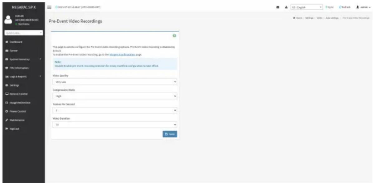
text_image
NEGARAC SP-X ELELTR AVS 2021 PROSETS EXC Host Online Quick Links... Dashboard Semner System Inventory File Information Logic & Report's Settings Remode Control Inteag/Reductbox Power Control Maintenance Sign out Pre-Event Video Recordings This page is used to configure the pre-event video recording options. Pre-event video recording is highly default. To enable the Pre-event video recording, go to the Windows Configuration page. Refer: Disable to enable pre-event recording selection for newly modified configuration to take effect. Video Quality Very Low Compression Marks High Frames Per Second 1 Video Transition 10 Save Home Settings - Sales Auto settings The Cross Video Recordingsa) To set video quality, select a resolution (Very Low, Low, Average, Normal, High) from the drop-down list of Video Quality.
b) To set compression mode, select a compression mode (high, normal, low, no) from the drop-down list of Compression Mode.
c) To set number of frames per second, select frames/sec (1-4) from the drop-down list of Frames Per Second.
d) To set duration of video, select second (10-60) from the drop-down list of Video Duration.
e) Click Save to save the changes made on Pre-Event Video Recording.
- Click Save to save the changes made on Video Trigger Settings.
Video Remote Storage
To configure Video Remote Storage, click Video Recording > Auto Video Settings > Video Remote Storage. A Sample screenshot of Video Remote Storage is as shown below.

text_image
NEGARAC SP-X 12.08.30 JAY 9 2021 MEXICO-IFC Trust Online Quick Limits... Outboard Server Typobek Inventory File Information Loga & Requests Settings Remedy Control Image Monitoring Power Control Maintenance Sign out Video Remote Storage Record Video to Remate Server Maximani Eventx 2 Maximani Duration (sec) 26 Maximani Size (MB) 5 Service Address Connect IP or Head name Push to server reg. Host from childrens Share Type JVS CHS Domain Name Downloadable Password USB US - English Logic Test with Admins Power Settings: Video / Auto sendings / Video Remote StorageProcedure
- Check Record Video to Remote Server to enable the Remote Video Support.

Note: By default, video files will be stored in local path of BMC. If remote video support enabled, the video files will be stored only in remote path, not within BMC.
- Enter Dumps value of the video in the Maximum Dumps field.
- Enter maximum duration of the video in the Maximum Duration (Sec) field.
- Enter maximum size of the video in the Maximum Size (MB) field.

Note: The Maximum Duration of the video should be in the range from 1 to 3600 seconds. The Maximum Size of the video should be in the range from 1 to 500 MB.
The Maximum Dumps should be in the range from 1 to 100. The recorded video file should meet either the size constraint or duration constraint, according to the configured settings, depending on which constraint is met first.
- Enter the server address in the Server Address field.

Note: Server address will support the following:
Address (Both IPv4 and IPv6 format).
FQDN (Fully qualified domain name) format.
-
Enter the source path in Path in Server field
-
Select the Share Type (NFS/CIFS). If the selected share type is (CIFS), enter the domain name, user name, and password in the Domain Name, Username, Password field respectively.
-
Click Save to save the settings.
Pre-Event Video Recording
Pre-Event Video Recordings is used to configure the Pre-Event video recording options. Pre-Event video is disabled by default. To enable the Pre-Event video recording, go to Settings >Video Recording >Auto Video Settings >Video Trigger Settings.
Pre-Event video recording files will be named as per event captured. For example - if any video is recorded for Crash Event, the recorded file will be named as pre_crash_video_x.dat, where x is file count, similarly if it is recorded for reset event it will be named as pre_reset_video_x.dat.
SOL Settings
To open SOL Set page, click Settings > Video Recording > SOL Settings from the menu bar. A sample screenshot of SOL Settings page is shown below.
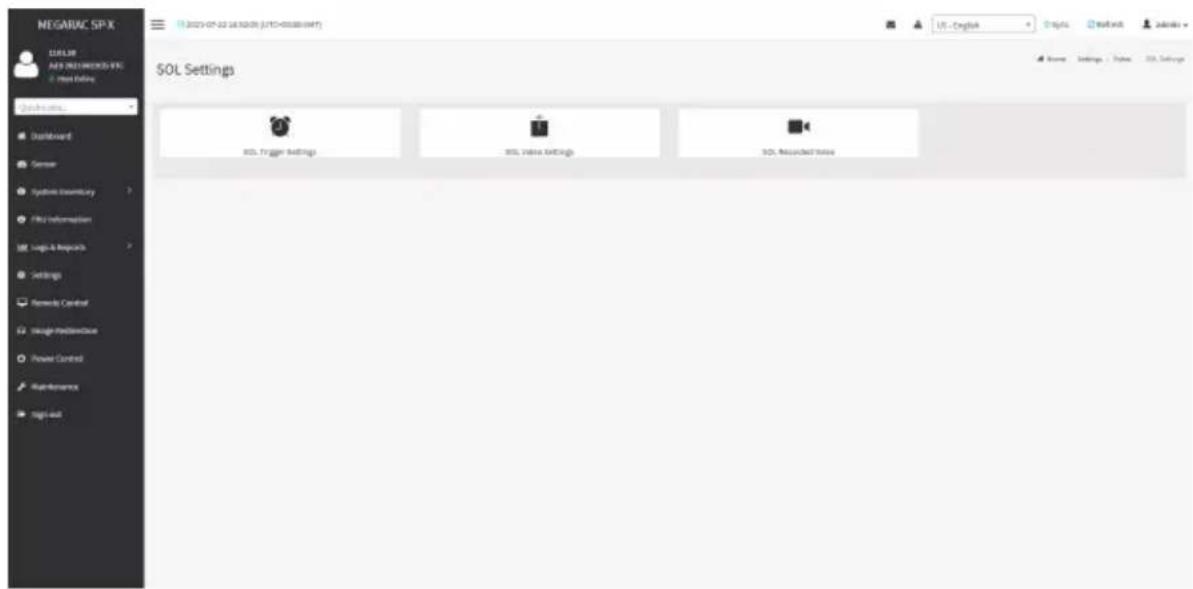
text_image
NEGARAC SPX BLUEB AVEN PRESTOCKS VIX: Next Options QUICKING... Dashboard Server Systems Inventory Fills Information Logic & Reports Settings Remote Control Image Monitoring Power Control Maintenance Big out 19.2023-07-22 18:52:00 (JYTD-000000049) US - Englink Projects Networks Name Settings 1 / Pages SQL Settings SQL Settings SQL Value Settings SQL Received StatusThe fields in the SOL Settings page are explained below.
SOL Trigger Settings
The SOL Trigger Settings page shows the list of available events.
• Critical Events (Temperature/Voltage)
• Non Critical Events (Temperature/Voltage)
• Non Recoverable Events (Temperature/Voltage)
• Fan state changed Events
- Watchdog Timer Events
- Chassis Power on Event
- Chassis Power off Event
- Chassis Reset Events
- LPC Reset Events
• Date and Time Events
A sample screenshot of SOL Trigger Settings page is shown as below.

text_image
MEGARAC SP-X MELON APR DISTRICTED-SPX Input Edition SOL Trigger Settings Critical Events (Temperature/Settings) Non-Critical Events (Temperatures/Voltage) Non-Personal Events (Temperature/Voltage) Par value changed Events Matching Theme Events Chassis Power Str Events Chassis Power Off Events Chassis Reset Events LPC Reset Events Beta Load Theme Event SaveProcedure
- Check the events to be enabled to configure which event on the page will trigger the SOL video recording option to start.
- To set particular Date and Time Event, check the option Date and Time Event.
a) Choose the month, day and year in the Date field.
b) Enter the Time in hh:mm:ss format in the Time field.

Note: The date and time should be in advance to the system date and time.
- Click Save to save the changes.
SOL Video Settings
This page allows you to configure recorded video files. The sample screenshot and various fields of SOL Video Settings are given below.

text_image
MEGARAC SP-X MELON MEN RECOMMENDED VIE Input IDs SQL Server Log Size (MB) 326 Log file content: 7 Recorded Videos to Reiterate Review Server Address Server/For High volume Host to server log: Web Services Mark Type NPS OPS Database Market Shareholder Platform() SaveProcedure
- Enter the preferred log size in the Log Size (KB) field. The maximum log size supported is 128 KB.
- Enter log file count in the Log File Count field. The maximum log file count is 1.
- Check/uncheck Record Video to Remote Server to enable/disable Remote Video support.

Note: By default, video files will be stored in local path of BMC. If remote video support enabled, the video will be stored only in remote path, not within BMC.
- Enter server address in the Server Address field.

Note: Server address will support the following:
Address (Both IPv4 and IPv6 format).
FQDN (Fully qualified domain name) format.
- Enter the source path in Path in Server field.

Note: Path must be alpha-numeric and the special characters '-' (hyphen), underscore), '@'(at sign) are allowed.
-
Select the Share Type (NFS/CIFS). If the selected share type is (CIFS), enter the domain name, user name, and password in the Domain Name, Username, Password field respectively.
-
Click Save to save the settings.
SOL Recorded Video
This page displays the list of available recorded video files on the system. Click on Download icon to download and save the video. Click on Delete icon to delete the selected video.
A sample screenshot of SOL Recorded Video is given below.
text_image
NEGARAC SP-X ECLX3E AUY 2021 PRODUCS IFC Host Online Quick Links... Qualiforand Semner Systems Inventory File Inferences Logic & Resources Settings Remends Control Image-Information Power Control Maintenance Tag in out SOL Recorded video S.No # File Name # File Information # Name Settings Sales SQL SOL Recorded Video2-6-17 Fan Profile
The Fan Profile page allows you to add new fan profile or edit fan profile.
A sample screenshot of the Fan Profile is given below.
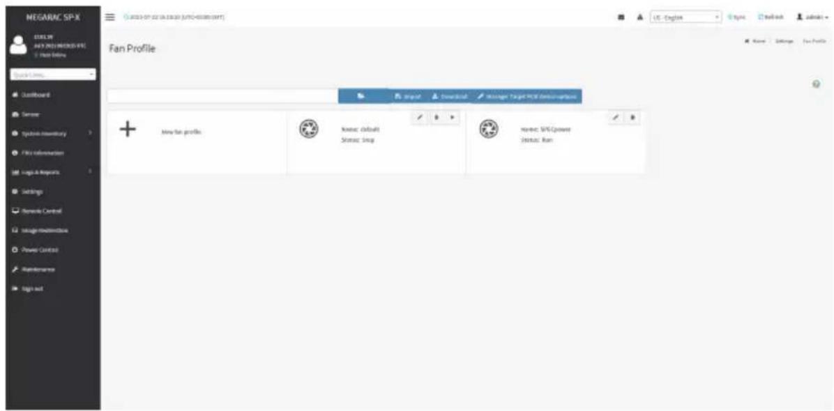
text_image
NEGARAC SP-X BLUE BY AUY 2021 NEWSPX FILE + List Entry Quick Links Lastboard Summer Typical inventory File information Logo & Reports Settings General Control Usage/Modestock Power Control Maintenance Sign out Fan Profile Input Download Manager Target PCV Desivatives + May-fan profile Name: default Status: Song Name: SPS/Cpower Status: RunNew Fan Profile
To add new fan profile, click the New fan profile tab.

text_image
MEGARAC SP-X MAGULAR ANY INSURANCE & PC 1. Host Privacy Edit New Fan Profile Name: NEW_PROFILE Policy: Algorithm Session Type Initiation Duty 0 Step Temperature 2 200 Sensor Fan Policy Execute Condition CPU/Map (Mb) 0 Accessible Issue: N/A P120 Devio: In each case possible device, ignore this execute condition Policy Reference Table Reference: 0 Entry (%) 247 200 New Options Settings New Profile Edit New Fan Profile Data - Graphs Settings New Profile Edit New Fan ProfileProcedure
- Name the fan profile in the Name field.
- Choose the mapping function of temperature and fan speed for the fan profile in the Algorithm field.
-
Select sensory type in the Sensor Type field.
-
Set the fan speed when the system is powering on in the Initialize Duty field.
- Select the sensor you want to include in this profile in the Sensor field.
- Select the fan you want to include in this profile in the Fan field.
- Click New in the Policy Reference Table field to create a new sensor value & fan speed duty mapping table.
- Set reference temperature and fan speed duty in the Policy Reference Table field.
- Click Save on the top side to save the configuration.
- Click the arrow icon to run the fan profile.
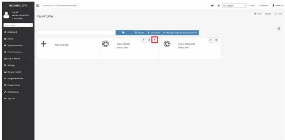
text_image
NEGARAC SP-X CBL3F JUL 2021 NOCKOS IFC Host Online Quick Links... Outboard Sensor Systems Inventory File Information Logic & Monarch Settings Remode Control Usage Infrastructure Power Control Maintenance Sign out Fan Profile Import Download Messages Target PCB ResourceAccess + new fan profile Status: defaults Status: Status: SPCpower Status: Main2-6-18 Power Consumption
Items in Power Consumption Reading displays current power consumption reading. You are allowed to configure power limit in the Power Consumption Limit field.

text_image
NEGARAC SP-X 12.0 LTR AUY'S NEGARAC SP-X Host Online Quick limits... Open/Forward Stimular System Inventory FPU Information Logic & Resources Settings Bemands Control Straight Read/Reduce Power Control Maintenance Sign out Power Consumption Reading Current Power Consumption (W) 237 Minimal Power Consumption (N) 219 Maximal Power Consumption (M) 258 Average Power Consumption (R) 252 Power Consumption Limit Enabled Power Consumption Limit: 1 Correction Time Limit (6000-600000 millisecond) 6000 Sampling Time (1, 1400 seconds) 1 Exception Action: No Action US - English English Read/ack Admins Name - Power ConsumptionProcedure
- Check Enabled to enable Power Consumption Limit.
- Set Power Consumption Limit.
- Set Correction Time Limit (6000-600000 millisecond).
- Set Sampling Time.
- Set Exception Action (No Action, Hard Power Off system and log event to SEL, Log event to SEL only).
2-6-19 IMPI Interfaces
You are allowed to configure the IPMI interfaces in this page.

text_image
MEGARAC SP-X CUELS API (RUSTIMICS) EX - Next Online Quick Belize... Dashboard Server Syncbase Inventory File Information Logo & Resources Settings Networks Central Straight Media Channel Power Control Web Resources Tags Out iPMI Interfaces IPRI Data LMI IPRI Data CXCR Google USE - English Hotbox Networks Home - Settings - USB InterfaceProcedure
- Check IPMI Over LAN to enable IPMI over LAN.
- Check IPMI Over KCS to enable IPMI over KCS.
- Click Save to save the configuration.
2-6-20 RAID Management
The RAID Management page allows you to view the Storage Summary, RAID Controller information, Physical Device Information, Logical Device Information and Event Log.
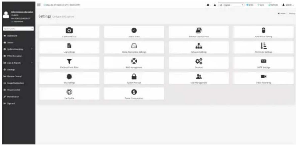
text_image
SNL Server Information 01:46:20 Dec 9 2022 12:43:28 GMT © Your Daily Settings Configur SNCL Options Camera NAVES Data & Time Internal User Resources AVAD Mouse Setting Log Settings Hardware Infrastructure Settings Network Settings Main Order Settings Platform Switch Filter R&D Management Services SMTP Settings SSL Settings System Firewall User Management Video Recording Fan Profile Power ConsumptionRAID Controller Information
To open the RAID Controller Information, click Settings > RAID Management > RAID Controller Information from the menu bar. A sample screenshot of RAID Controller Information section is shown below.
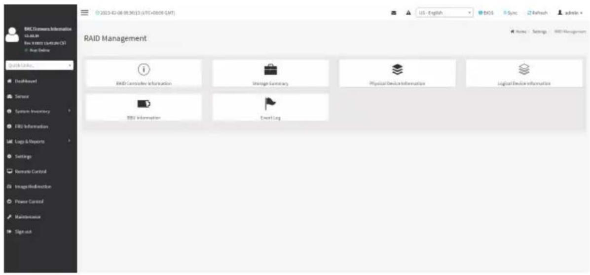
text_image
RAID Management R&D Controller Information Storage Summary Physical Device Information Logical Device Information RSD Information Event Log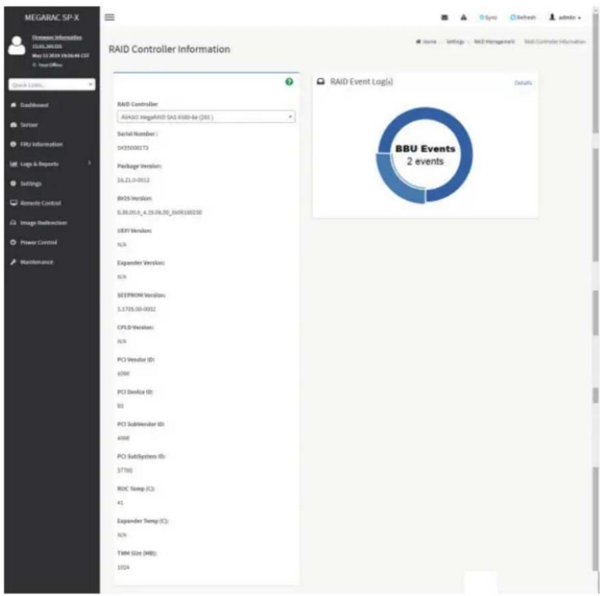
pie
BBU Events 2 events | Category | Count | | :--- | :--- | | RAID Controller | AIAGO MegaRIVID SAS 8580-8e (381) | | Serial Number | 1 | | S45500E1T3 | 0 | | Package Version: | 24.21.0-0012 | | BIOS Version: | 6.38.05.0_A_19.06.00_Ex09:180200 | | SEPI Version: | N/A | | Expander Version: | N/A | | SEEPROM Version: | 5.1705.00-0052 | | CPLD Version: | N/A | | PCI Vendor ID: | 4098 | | PCI Device ID: | 03 | | PCI SubRenderer ID: | 4098 | | PCI SubSystem ID: | 37760 | | ROC Temp (C): | 41 | | Expander Temp (C): | N/A | | TMM Size (H8): | 1024 | RAID Event Log(s) Details: BAU Events 2 events
Note: You can get RAID Controller Information only when Host is in Power ON state.
Serial Number : Displays the Serial number of the RAID Controller.
Package Version : Displays the Package Version number of the RAID Controller.
BIOS Version : Displays the BIOS Version number of the RAID Controller.
UEFI Version : Displays the UEFI version number of the RAID Controller.
Expander Version : Displays the Expander Version number of the RAID Controller.
SEEPROM Version : Displays the SEEPROM Version number of the RAID Controller.
CPLD Version : Displays the CPLD Version number of the RAID Controller.
PCI Vendor Version : Displays the PCI Vendor Id of the RAID Controller.
PCI Device Version : Displays the PCI Device Id of the RAID Controller.
PCI SubVendor ID : Displays the PCI Subvendor Id of the RAID Controller.
PCI SubSystem ID : Displays the PCI Sub-Device Id of the RAID Controller.
ROC Temp (°C) : Displays ROC temperature.
Expander Temp (°C) : Displays the Expander temperature.
RAID Event Log : Displays a graphical representation of all events incurred by the RAID Controller and %occupied/available space in logs. If you click on the Details link, you can view a list of available events.
Storage Summary
This tab displays a brief summary of storage devices available under the RAID controller. To open the Storage Summary section, click Settings > RAID Management > Storage Summary from the menu bar. A sample screenshot of Storage Summary section is shown below.
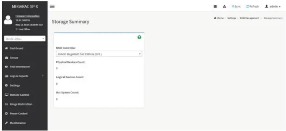
text_image
MEGARAC SP-X Firmware Information 12.01.201225 May 13 2019 19:20:46 CST Host Office Quick Links... Dashboard Sensor FRU information Logs & Reports Settings Remote Control Image Redirection Power Control Maintenance Storage Summary RAID Controller AvAGO MegaRAID SAI 9380-Be (261 ) Physical Devices Count: 0 Logical Devices Count: 0 Hot Spares Count: 0 Sync Refresh admin Home - Settings - RAID Management - Storage SummaryPhysical Devices Count : Displays the number of Physical Devices connected to the controller. Logical Devices Count : Displays the number of Logical Devices configured and available under the controller.
Physical Device Information
This tab displays the details about the Physical Devices connected to the RAID controller. To open the Physical Device Information, click Settings > RAID Management > Physical Device Information from the menu bar. A sample screenshot of Physical Device Information section is shown below:

text_image
MEGARAC SP-X Filemore Information 12.01.201225 Apr 24 2013 10:46:56 CST © Host Office Quick Links... Dashboard Sensor FRU Information Logs & Reports Settings Remote Control Image Redirection Power Control Maintenance Physical Device Information Select the RAID Controller AVAGO MegaRAID SAS 9460-BI (260) Clear Foreign Configuration Device ID Controller Media Type State Slot Speed Link Speed Size Temp (GB) Temp (C) Foreign Dedicated HotSpars Information (Logical Device Name) 1 AVAGO MegaRAID SAS 9460-BI (260) HDD Online 4 3.0Gb/s 3.0Gb/s 298 44 - - 3 AVAGO MegaRAID SAS 9460-BI (260) HDD Dedicated HOT_SPARE 5 6.0Gb/s 6.0Gb/s 931 39 - aaaa 4 AVAGO MegaRAID SAS 9460-BI (260) HDD UNCONFIGURED_GOOD 7 6.0Gb/s 6.0Gb/s 465 40 - - 9 AVAGO MegaRAID SAS 9460-BI (260) HDD Online 3 6.0Gb/s 6.0Gb/s 465 37 - - 10 AVAGO MegaRAID SAS 9460-BI (260) HDD Online 0 3.0Gb/s 3.0Gb/s 298 36 - - 135 AVAGO MegaRAID SAS 9460-BI (260) HDD UNCONFIGURED_GOOD 255 Not Defined Not Defined 0 0 - -Select the RAID Controller : To view the details of specific RAID Controller.
Device Id : Displays the Device ID of physical device available under selected RAID controller.
Controller : Displays the name of RAID controller to which the physical device is attached.
Media Type : Displays the media type of physical device that is attached to the selected RAID controller.
State : Displays State of the Physical Device (either online, or offline).
Slot : Displays Slot number, through which Physical Device is connected to the back plane.
Speed : Displays the speed of the Physical Device in Gb/s.
Link Speed : Displays the link speed of the Physical Device in Gb/s.
Size (GB) : Displays the Size of the Physical Device.
Temp (°C) : Displays the Temperature of the Physical Device.
To perform additional operations, click on the slot or expand the (+) icon. A sample screenshot is shown below.

text_image
MEGNAC SP-X www.information 12.08.2016 For 21 SEP23/04/05/21our offer
Device ID: Continuous Video Type: Slade Signal Speed Link Speed Slow (GB) Temp (K) Foreg 1 AVGO MegaPAID GAS 9420 4 (NO.) Online 4 2.0GHz 2.0GHz 228 44 2 AVGO MegaPAID GAS 9420 4 (NO.) Connection - Off SNPs 5 8.0GHz 9.0GHz 621 29 27.00 4 AVGO MegaPAID GAS 9420 4 (NO.) NetworkICURED GOOD 7 9.0GHz 9.0GHz 455 40 - 9 AVGO MegaPAID GAS 9420 3 (NO.) Online 3 9.0GHz 9.0GHz 455 37 - 10 AVGO MegaPAID GAS 9420-3 (NO.) Online 3 9.0GHz 9.0GHz 236 35 - 120 AVGO MegaPAID GAS 9420-3 (NO.) NetworkICURED GOOD 355 Net Detrout Net Detrall 6 0 - - -View Physical Device Information: Click View Icon to view more details about the Physical Device Information, including Device Id, Vendor Id, Product Id, Serial Number, Power State, and Interface Type. A sample screenshot of View Physical Device Information page is shown below.

text_image
MEGARAC SP-X Enerware Information 2.03.8.2014 Dec 9 2016 0027161 RT @ host office Quick Link Dashboard Sensor FRU Information Lungs & Reports Settings Remote Control Image Redirection Power Control Maintenance Sign out Physical Device Information Device ID 25 Vendor ID ATA Product ID INTEL SGD/SC2R812 Serial Number BTWL332R09OF120LGN Power State Spun Up Interface Type SATALogical Device Information
This tab displays the details about the Logical Devices configured under the RAID controller. To open the Logical Device Information section, click Settings > RAID Management > Logical Device Information from the menu bar. A sample screenshot of Logical Device Information section is shown below:
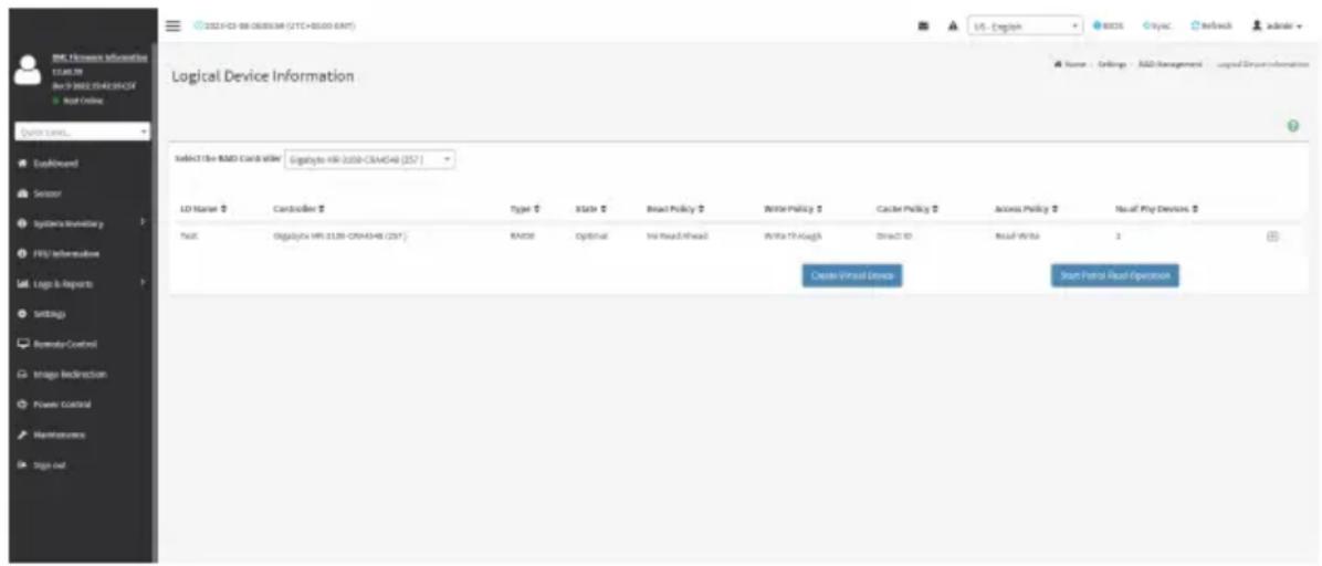
text_image
2023-03-08 06:05:34 (CYC+85.00 GMT) Logical Device Information Select the RMS Card suite - Digitality HR-2028-CSA/CSA (257) LD Name Contodors Type State Broad Policy Write Policy Cache Policy Access Policy New Play Devens True Digitality HR-21.00-CRA/CSA (257) RMOD Optimal No Read/Thread Write TR-Kough Direct ID Read Write 2 Create Virtual Devices Start Patrol Real Operation BMC Software Information 12.00.39 Rev 0 2022 10:40:25:45:55 Not Online Source: Email - RMS Management - unpaid Deport information Logistics Devoluency FRII Information Logic Is Reports Sorting Remain Control Image Bindirection Power Control Maintenance Trags outSelect the RAID Controller : To view the details of the Logical devices configured under the specific RAID controller.
LD Name : Displays the name of the Logical Device configured under selected RAID controller.
Controller : Displays the Name of the RAID Controller under which the Logical Devices are configured.
Type : Displays the type of RAID level in which the Logical Device is configured, e.g. RAID O or RAID 1 etc.
State : Displays the state of the Logical Device (either online or offline).
Read Policy : Displays the Read Policy details of the Logical Device.
Write Policy : Displays the Write Policy of the Logical Device.
Cache Policy : Displays the Cache Policy details of the Logical Device.
No. of Physical Devices : Displays the number of Physical Devices available under the specific Logical device.
To perform additional operations, click on the slot or expand the (+) icon available for each Logical Device. A sample screenshot is shown below.

text_image
LOGICAL DEVICE INFORMATION Select the RAI5 Controller: Logical Site:0338-CPNCA48 (2017) L3 Name 2 Controllar 2 Type 2 State 2 Read Policy 2 Write Policy 2 Cache Policy 2 Access Policy 2 Next Play Services 2 Total: Logical Site:0338-CPNCA48 (2017) RJ/0338 Digital New Read Interface Write Through Direct To Go Read Account 1 Create Virtual Devices Next Panel Real OperationsView Physical Device info for selected Virtual Device : Clicking on the icon will display the Logical Physical Device Information page, It lists the information of physical devices configured for specified logical device. A sample screenshot of View page is shown below:
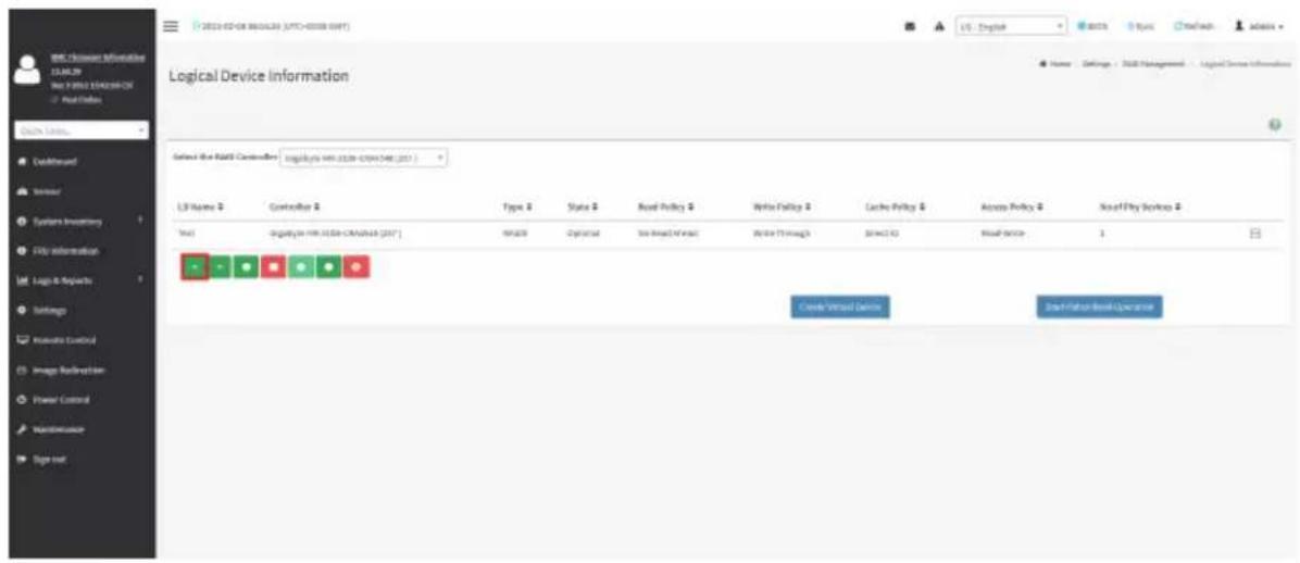
text_image
2023-02-08 06:00:59 (UTC+00:00 GMT) Logical Device Information Select the RAI's Controller: Log-Rate Wi-Fi 0139-0794148 (2017) LS Home # Controller # Type # Status # Royal Policy # Write Policy # Cache Policy # Access Policy # New/Fly Settings # Test: -Digital Wi-Fi 0139-0794148 (2017) MS/OS 2p/OS/SD 36.8kV/MS/OS 26.6kV Through SPAC ID Real Device 1 Create Virtual Device Start/Start Real Operations
text_image
Digital Commerce Information SIGMA-CTRL File 1: 2022 SIGMA-CTRL Visual Basic Logical Physical Device Information Selected SIGMA-Controller/Stragency M1.000-CMS4348 (257) Level Devices (B) of Logical Devices (C) Device ID # Controller Name Type # State # Slot # Speed # Link Speed # Size (GB) # Temp (K) # OK Sigalyte-WIR-2000-CMS4348 (257) HSD Online 1 6.9Gb/s 6.8Gb/s 558 55Check Advanced Properties : Click icon to view the advanced properties of the selected Logical device. A sample screenshot is shown below.
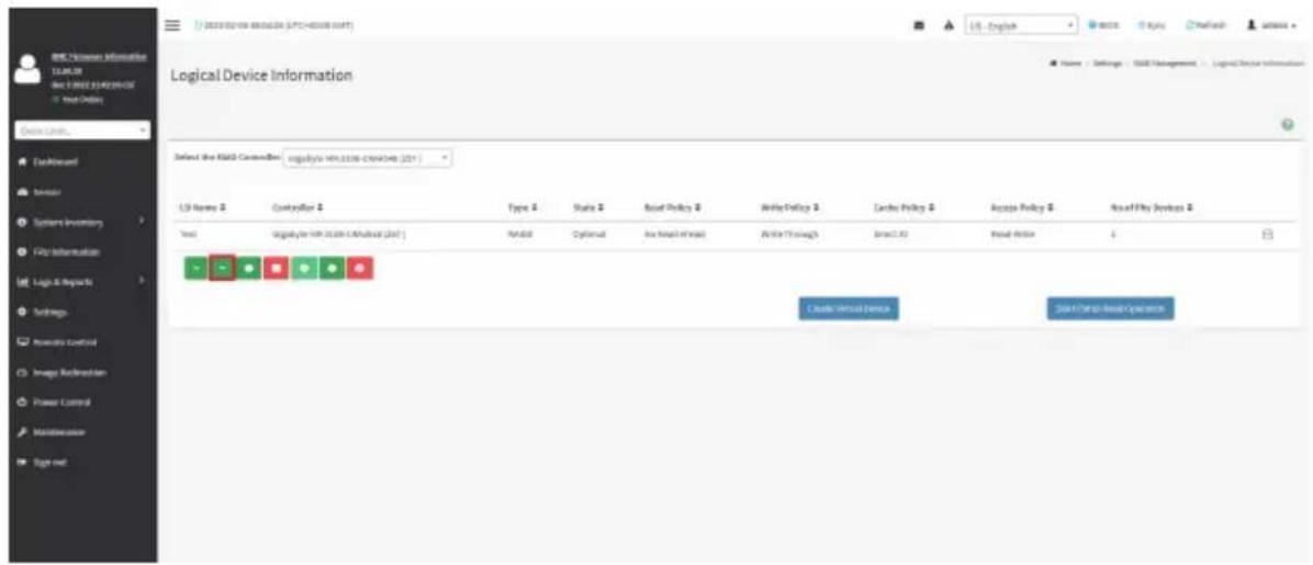
text_image
Logical Device Information Select the KIID Controller: logStyle: 401336-264048 (201) LSI Name # Catalyst # Type # Style # Bond Policy # Write Policy # Cache Policy # Access Policy # RealPlay Devices # Text: LogStyle: 401336-264048 (201) NADL Cytically Insured Through Breakout Create Virtual Device 2013/09/00 RealPlay Operations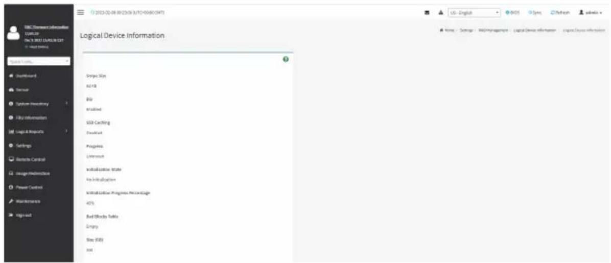
text_image
BMC Command Information E:\WINDOWS\CN 3.0001\SYSTEM\EXT - Host Banking Logical Device Information Done Stay all Park File Installed SDD-Cacking Download Progress Unknown Installation Status In Implementation Install Customer Progress Percentage 45% Bad History Table Empty Stay (SBY) rootDelete Virtual Drive : Click icon to delete selected virtual device. A pop-up message prompts you to confirm your choice. Upon confirmation, you will be informed about the status.
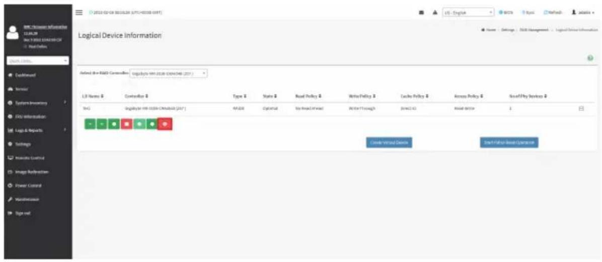
text_image
Logic Device Information Default for R&D Controller: Logically win 2018 (2019/2020) (2017) LSI Name: Contentlog Type: Style: Real Policy: Write Policy: Cache Policy: Access Policy: New/Full Services: LOG: Digital for WIN-1039-CAMRSLB [247] MPDB: Digital: Web-based Web: Write Through: Network ID: Real Device: 1 Create Virtual Devices Start Virtual Base ExperienceTo Create Virtual Device:
- Click Create Virtual Device to create Logical Volume of the Device. A sample screenshot of Create Virtual Device page is shown below.
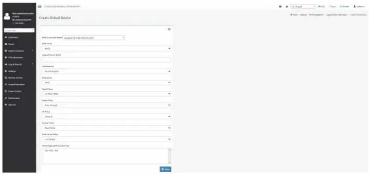
text_image
Create Virtual Device Skill Level ASCE Logical Privacy Rules Installation Non-Initialization Bridge Size Level Need Policy To Find Mixed Write Policy Apply Through at Policy Draw It Resume Policy Power Links Seed Case Policy C:\Target Form\Figure\Physical\Final URL: 400-866 Data Lfd. Global B2.123 F1.256 Network Software Name - Design - Web Management - Logical Data Information - Create Virtual Device- Select Controller Name from the drop-down lists.
- Select RAID Level from the drop-down lists. A sample screenshot of RAID Levels is as shown below:
Note: Only RAID Levels RAID00, RAID10, RAID50 and RAID60 will support Span Creation.

text_image
Create Virtual Device With Controls Name: Signify the device to create a device (SPT) Build Local Auto Model AutoBook Information no information Print Size Size Print Policy No Print Wizard Write Policy Allow Through All Policy Direct IT Adjust Policy Read Style Show Direction Policy Use Change ########## and click any code 326 - 4021-098 Save- Enter the depth of the Span in Span Depth field.
- Enter the number of Drives in Drives per Span field.
Note: UnConfigured Physical Drives should be equal to multiples of Span Depth and Drives per Span.
-
Select UnConfig Physical Drives from the drop-down lists.
-
Click Create Span for mapping Span Id's to the selected Physical Drives. The mapped Span Id for the selected Unconfigured Physical Drives will be displayed as shown in the above screenshot.
-
Enter Logical Name of the Device.
-
Select Initialization type from the drop-down lists.
-
Select Stripe Size (KB), Read Policy, Write Policy, IO Policy, Access Policy, Disk Cache Policy and UnConfigured Physical Drives details from the respective drop-down lists.
-
Click Save to add the information to the Logical Device Information. The information will be added and displayed in the Logical Device Information page.
To Delete Logical Device
Select the Device to be deleted and click Delete Logical Device to delete the selected logical volume. The selected virtual device will be deleted.
Event Log
This page displays all the RAID Controller events occurred that has been already configured. To open the Event Log section, click Settings > RAID Management > Event Log from the menu bar.
Note: All the events mentioned here are read-only and cannot be edited.
A sample screenshot of Event Log section is shown below:

text_image
Event Log Select the RMB Controller: Gigabyte MR-3108-CMA4548 (257) Select the Event Type All Events Clear Event Log Controller 1 Gigabyte MR-3108-CMA4548 (257) Gigabyte MR-3108-CMA4548 (257) Gigabyte MR-3108-CMA4548 (257) Gigabyte MR-3108-CMA4548 (257) Gigabyte MR-3108-CMA4548 (257) Gigabyte MR-3108-CMA4548 (257) 190 02/06/2023 370 LP Events Info Events Gigabyte MR-3108-CMA4548 (257) Gigabyte MR-3108-CMA4548 (257) Gigabyte MR-3108-CMA4548 (257) Gigabyte MR-3108-CMA4548 (257) Gigabyte MR-3108-CMA4548 (25T) Gigabyte MR-3108-CMA4548 (25T) Gigabyte MR-3108-CMA4548 (25T) Gigabyte MR-3108-CMA4548 (25T) Gigabyte MR-3108-CMA4548 (25T) Gigabyte MR-3108-CMA4548 (257) Gigabyte MR-3108-CMA4548 (257) Gigabyte MR-3108-CMA4548 (257) Gigabyte MR-3108-CMA4548 (257) Gigabyte MR-3108-CMA4548 (25T) 190 02/06/2023 370 LP Events Info Events Gigabyte MR-3108-CMA4548 (257) Gigabyte MR-3108-CMA4548 (257) Gigabyte MR-3108-CMA4548 (257) Gigabyte MR-3108-CMA454A (257) Gigabyte MR-3108-CMA4548 (257) Gigabyte MR-3108-CMA4548 (257) Gigabyte MR-3108-CMA4548 (257) Gigabyte MR-3108-CMA4548 (257) Gigabyte MR-3108-CMA454A (257) Gigabyte MR-3108-CMA454A (257) Gigabyte MR-3108-CMA454A (257) Gigabyte MR-3108-CMA454A (257) Gigabyte MR-3108-CMA454A (257) Gigabyte MR-3108-CMA454B (257) Gigabyte MR-3108-CMA454B (257) Gigabyte MR-3108-CMA454B (257) Gigabyte MR-3108-CMA454B (257) Gigabyte MR-3108-CMA454B (257) Gigabyte MR-3108-CMA454A (257) Gigabyte MR-3108-CMA454A (257) Gigabyte MR-3108-CMA454A (257) Gigabyte MR-3108-CMA454A (257) Gigabyte MR-3108-CMA454C (257) Gigabyte MR-3108-CMA454C (257) Gigabyte MR-3108-CMA454C (257) Gigabyte MR-3108-CMA454C (257) Gigabyte MR-3108-CMA454C (257) Gigabyte MR-3108-CMA454D (257) Gigabyte MR-3108-CMA454D (257) Gigabyte MR-3108-CMA454D (257) Gigabyte MR-3108-CMA454D (257) Gigabyte MR-3108-CMA454D (257) Gigabyte MR-3108-CMA454E (257) Gigabyte MR-3108-CMA454E (257) Gigabyte MR-3108-CMA454E (257) Gigabyte MR-3108-CMA454E (257) Gigabyte MR-3108-CMA454E (257) Gigabyte MR-3108-CMA454F (257) Gigabyte MR-3108-CMA454F (257) Gigabyte MR-3108-CMA454F (257) Gigabyte MR-3108-CMA454F (257) Gigabyte MR-3108-CMA454F (257) Gigabyte MR-3108-CMA454A (26) Gigabyte MR-3108-CMA454A (26) Gigabyte MR-3108-CMA454A (26) Gigabyte MR-3108-CMA454A (26) Gigabyte MR-3108-CMA454A (26) Gigabyte MR-3108-CMA454A (26) Gigabyte NR-GOGBOBOWING-GOGBOBOWING-GOGBOBOWING-GOGBOBOWING-GOGBOBOWING-GOGBOBOWING-GOGBOBOWING-GOGBOBOWING-GOGBOBOWING-GOGBOBOWING-GOGBOBOWING-GOGBOBOWING-GOGBOBOWING-GOGBOBOWING-GOGBOBOWING-GOGBOBOWING-GOGBOBOWING-GOGBOBC + - - - - - - - - - - - - - - - - - - - - - - - - - - - - - - - - - - - - - - - - - - - - - - - - - - - - - - - - - - - - - - - - - - - - - - - - - - - - - - - - - - - - - - - - - - - - - - - - - - - - - Event DescriptionThe Event Log page consists of the following Fields.
Select the Event Type: This field is to filter the type of event to be viewed among all available events under specified RAID controller. The category could be either All Events, LD events, PD Events, Enclosure Events, BBU Events, SAS Events, Controller Events, Configuration Events and Cluster Events.
Note: Filtering can be done with the Events mentioned in the list. Once the Event Log category is chosen in the Event type drop-down list then the filtered events will be displayed with the Record ID, Time Stamp, Event Code, Event Type and Event Class.
Navigational arrows can be used to selectively access different pages of the Event Log.
Clear Event Log: To delete all the event logs.
Procedure
- Select the RAID Controller from the drop-down list.
- Select the Event Type from the drop-down list.
- To clear all events from the list, click Clear Event Log.
2-7 Remote Control
The system and browser requirements for Remote Control are given below.
System Requirements
- Client machine with 8GB RAM.
- If the client machine has 4GB RAM, there will be lag in Video/keyboard/mouse functionality.
Supported Browsers
- Chrome latest version.
- IE 11 and above.
- Firefox (with limited support).

Note: It is advisable to use Chrome or IE for H5Viewer, since Firefox has its own memory limitations.
To open the Remote Control page, click Remote Control from the menu bar. A sample screenshot of the Remote Control page is shown below.

text_image
NEGAIRAC SP-X E3L3.3F NYS RECORDED SFX View Before Quick URL... Default/Forward Server System repository PBU Information Logic & Resources Settings Networks Control Hedge Resource Power Control Maintenance Sign out Remote Control: Remove USB & DSL. HSV viewer USB will go to remote service settings. Launch/Attacker JV viewer launch/miss server Serial Over LAN Access Identify LED Status City Action Turn-DBY Turn-DFY Lighting Time (Seconds) Unlimited SaveThe fields in the Remote Control page are explained below.
H5Viewer: Launches the KVM.
JViewer: Downloads the jviewer file.
Serial Over LAN: Launches the HTML5 Serial Over LAN window.
Identify LED: Turns on/off the chassis identification LED.
H5Viewer
On the Remote Control page, click Launch H5Viewer. A sample screenshot of the H5Viewer page is shown below.
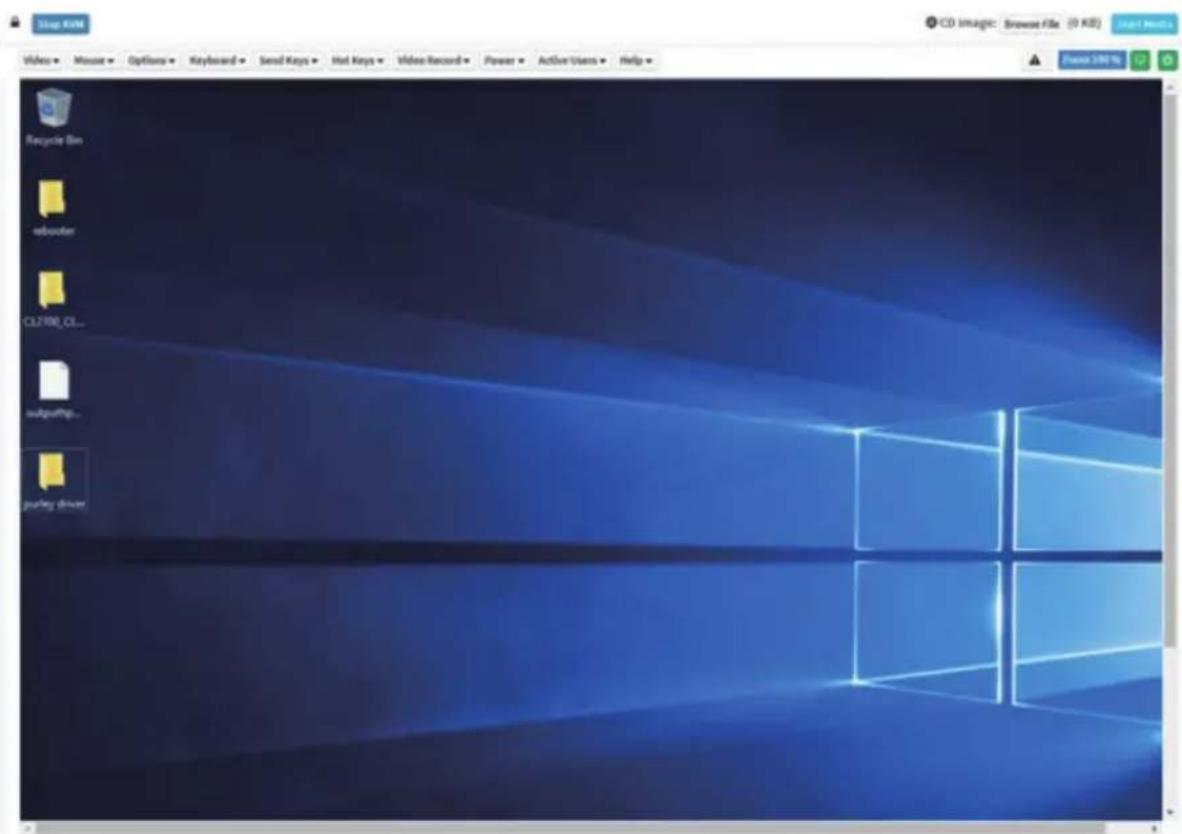
text_image
Stop KIM Video • Mouse • Options • Keyboard • Send Keys • Hot Keys • Video Record • Power • Active Users • Help • Recycle Bin reborder CL2100_CL... outputing... Puning Driver CD image: Browse File (0 KB) Save 396%Stop KVM: Stops the H5Viewer.
Video: Consists of the following items:
- Pause Video: Pauses Console Redirection.
- Resume Video: Resumes the Console Redirection when the session is paused.
- Refresh Video: Updates the display shown in the Console Redirection window.
Mouse: Contains the following items:
• Show Client Cursor: Shows or hides the local mouse cursor on the remote client system.
- Mouse Mode: Handles mouse emulation from local window to remote screen using either of the two methods. Only 'Administrator' has the right to configure this option.
- Absolute mouse mode: The absolute position of the local mouse is sent to the server if this option is selected.
- Other mouse mode: Sets the client cursor in the middle of the client system and will send the deviation to the host. This mouse mode is specific for SUSE Linux installation.

Note: Client cursor will be hidden always. If you want to enable, use Alt + C to access menu.
Options
Zoom In / Zoom Out: Allows you to adjust zoom level.
Partial Permission / No Permission: Enables/Disables the access privilege of the user.
Auto Detect / 256 Kbps / 512 Kbps / 1 Mbps / 10 Mbps / 100 Mbps: Adjusts the bandwidth.
YUV 420 / YUV 444 / YUV 444 + 2 color VQ / YUV 444 + 4 color VQ: Adjusts the color encoding mode.
0 Best Quality - 7: Allows you to adjust the screen resolution.
Keyboard: lists the host physical keyboard languages supported in H5Viewer.
- English U.S
- German
- Japanese
Send Keys: Enters items.
This menu contains the following sub menu items:
- Hold Down
- Press and Release
Hold Down: Contains the following items:
- Right Ctrl Key: Acts as the right-side
key when in Console Redirection.
• Right Alt Key: Acts as the right-sidekey when in Console Redirection. - Right Windows Key: Acts as the right-side
key when in Console Redirection. - Left Ctrl Key: Acts as the left-side
key when in Console Redirection.
• Left Alt Key: Acts as the left-sidekey when in Console Redirection. - Left Windows Key: Acts as the left-side
key when in Console Redirection. You can also decide how the key should be pressed: Hold Down or Press and Release.
Press and Release
- Ctrl+Alt+Del: Acts as if you depressed the
, and keys down simultaneously on the server that you are redirecting. - Left Windows Key: Acts as the left-side
key when in Console Redirection. You can also decide how the key should be pressed: Hold Down or Press and Release. - Right Windows Key: Acts as the right-side
key when in Console Redirection. - Context Menu Key: Acts as the context menu key, when in Console Redirection.
- Print Screen Key: Acts as the print screen key, when in Console Redirection.
Hot Keys: Adds the user configurable shortcut keys to invoke in the host machine.
The configured key events are saved in the BMC.
- Add Hot Keys: Enables User Defined Macros. Click Add to add a User Defined Macro.
Video Record: Contains the following items:
• Record Video: Starts recording the screen.
- Stop Recording: Stops the recording.
- Record Settings: Sets Video Recording Duration.

Note: The Maximum video file size allowed is around 40MB. If the video file size reaches its max size limit, the recorded file is downloaded and recording will be in progress until the configured video recording time is reached. The video file is saved as video_date-month-year_hr-min-sec_partno in client side video recording.
Users have to take care of saving the video files in different browsers.
When H5viewer focus is lost and if video recording is in progress, the recording will be stopped with a notification message and the recorded video file will be discarded. Due to browser limitation, Set timeout/set interval will be delayed from specified time of interval when browser window loses focus, Hence, video server will not send the video packets to H5viewer and so the video recording will be stopped.

Note: Windows 2016 installation takes 1 hour and 52 minutes to install on Ironman through the BMC ISO redirection.
Power: Performs any power cycle operation.
- Reset Server: Reboots the system without powering off (warm boot).
- Immediate Shutdown: Turns off the server immediately.
- Orderly Shutdown: Turns off the server in proper order.
• Power ON Server: Powers on the server. - Power Cycle Server: Performs server power control operation.
Active Users: Displays the active users and their system IP address. Active KVM Session can be terminated when there are multiple KVM Session from Master [FULL Privilege KVM Session].
Help: Displays information about H5Viewer.
Browse File: Selects the CD image file to be redirected to the host.
Start Media: Redirects the selected CD image file to the host.
Stop Media: Stops the CD media redirected to the host.
Zoom 100%: Displays the zoom level.
Host Display
- Display on: If you disable this option, the display will be shown on the screen in Console Redirection
- Display off: If you enable this option, the server display will be blank but you can view the screen in Console Redirection. If you disable this option, the display will be back in the server screen.
- Capture Screen: Takes the screenshot of the host screen and save it in the client's system.
Power ON/OFF: Power ON/OFF the server.
Procedure
- Click Launch H5Viewer to start video redirection.
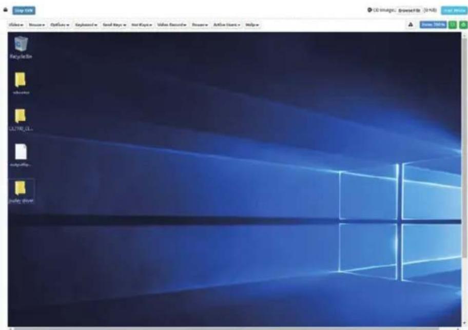
text_image
Stop Help File Edit View Insert Tools Help RecycleBox Adobe LUTR-CL My Documents My Documents CD Images, Browser files (3 KB) View Help Close Web- Click Browse File to select CD Image.
- Click Start Media to redirect the selected CD image file to the Host. A sample screenshot is as shown below.

text_image
CD Images: vite-server 7.0.xls_p449632 (70% KB) File Home Share View Message This PC + CD drive (E:\RHEL\7.0 Server Search CD drive (S) Desktop Downloads Documents Pictures The PC Desktops Documents Downloads Music Pictures Videos Local Disk (C:) CD Drive (E:\RHEL\7.0 Server Name Date-modified Type Size aditors 5/7/2014 2/18.0M File folder Image 5/7/2014 2/18.0M File folder images 5/7/2014 2/18.0M File folder sales 5/7/2014 2/18.0M File folder blueOffs 5/7/2014 2/18.0M File folder packages 5/7/2014 2/18.0M File folder release notes 5/7/2014 2/18.0M File folder repudita 5/7/2014 2/18.0M File folder discinfo 5/7/2014 2/18.0M DISINFOYA 1 KB TreemapYrsA 5 KB TUEA 4/6/2014 300.AIM File 9 KB GPS 3/6/2012 600.AIM File 10 KB streampages 5/7/2014 310.0M WIFI Files 1 KB SPM-SPG-KEY release beta 4/3/2014 620.AIM File 4 KB SPM-SPG-KEY release release 4/3/2014 620.AIM File 4 KB TRIAD.TSL 5/7/2014 310.0M TWL 1Kx 2 KB- To stop the CD Image redirection, click Stop Media.
JViewer
JViewer allows you to download the jviewer file. Click Launch JViewer to download the jviewer file.

Note: The jviewer file is used for launching Java executable files over the web or network.
Serial Over LAN
Serial Over LAN can launch the HTML5 Serial Over LAN window. Click Activate to launch the HTML5 Serial Over LAN window. A sample screenshot of the HTML5 Serial Over LAN window is shown below.
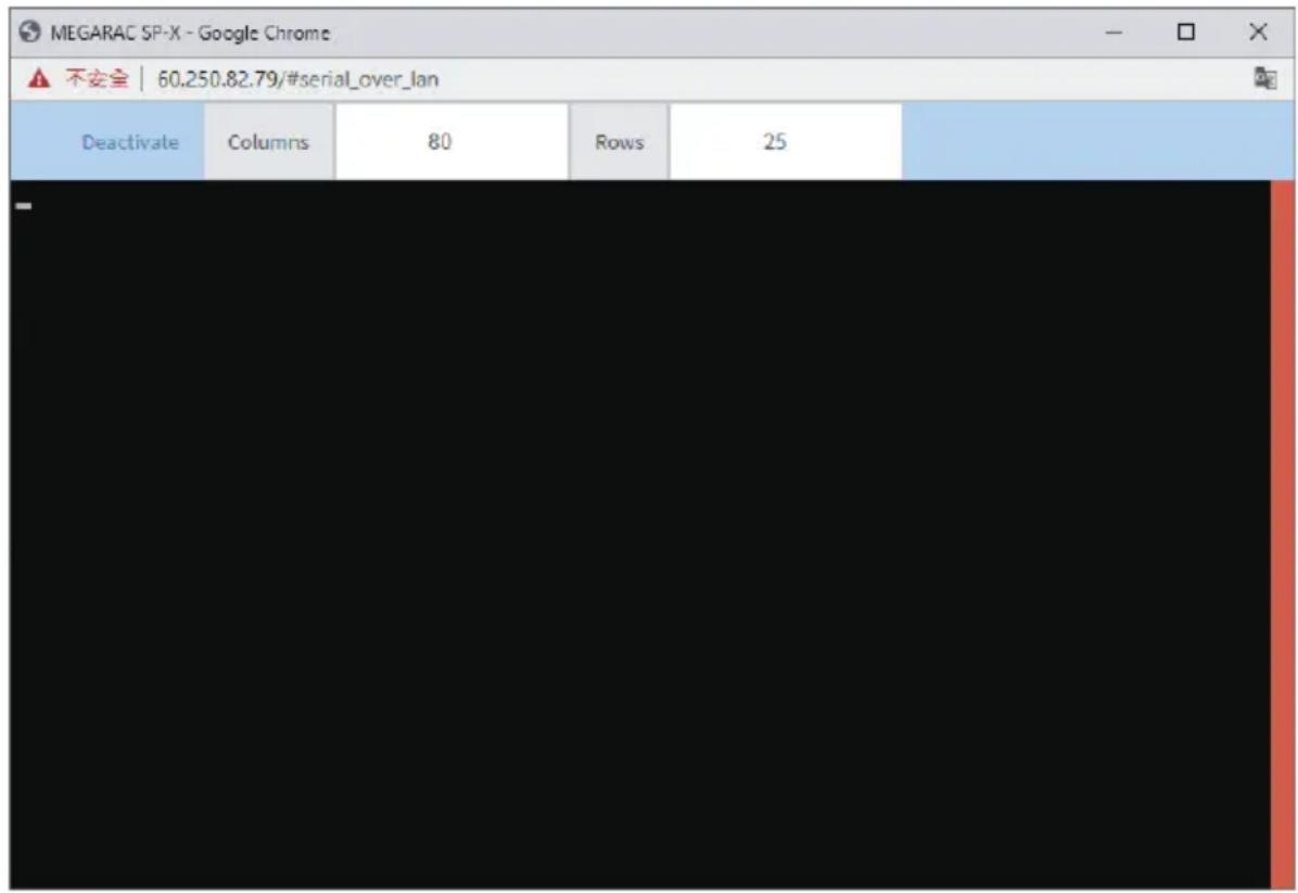
text_image
MEGARAC SP-X - Google Chrome ▲ 不安全 | 60.250.82.79/#serial_over_lan Deactivate Columns 80 Rows 252-8 Images Redirection
This page is used to configure the images into BMC for redirection. This can be done either by uploading an image into BMC or by mounting the image from the remote system.
To open the Image Redirection page, click Image Redirection from the menu bar. A sample screenshot of the Image Redirection page is shown below.
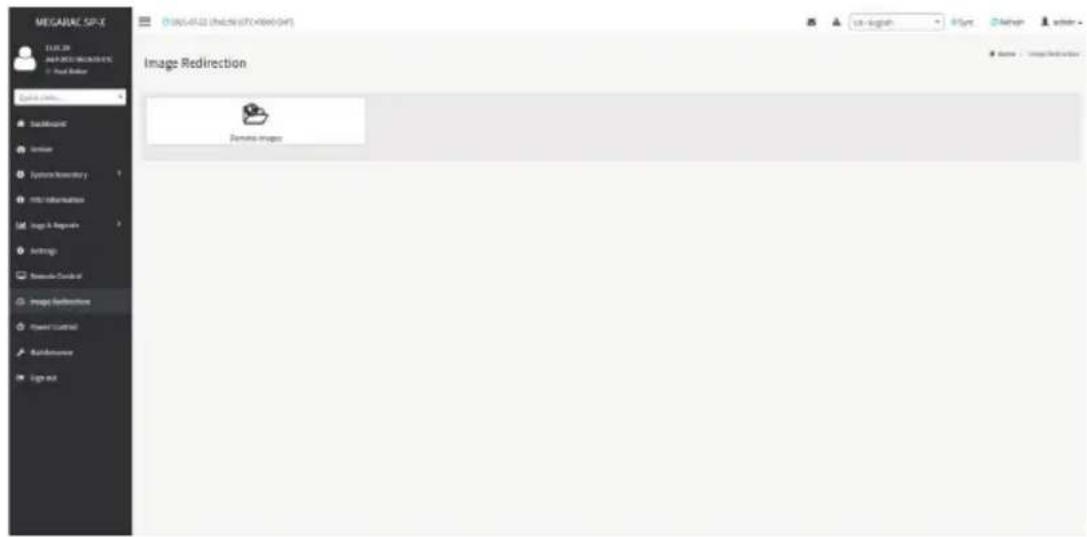
text_image
MEGAINE SPACE ELEC.03 MAGNETS MIGARES - Real Marker Data Source BackMap Internet Systems Inventory Intel Information Image & Image Settings Presentation Guide Image Refreshments Power Control Add和完善 Log mix Image Redirection Images images Name - ImageRedirectionThe fields in the Image Redirection page are explained below.
Remote Images: Allows you to configure images of remote media servers.

Note: VMedia Privilege only restricts initiating / starting media redirection. If a device is ready being redirected and attached to the host, then in host it will be visible as normal price. Hence it will be accessible to all the KVM sessions. Which includes 'KVM privilege only' sessions as well.
2-8-1 Remote Media
The Remote Media tab displays the configured images of remote media server on BMC.

text_image
MEGARAC SP-X 13:08:30 Aug 5 2016 47:15:34 UTC © Next Office Quick Lock... Downloaded Server Systems Inventory FXU Information Log 6 Requests Settings Runtime Control Image Redirect to Power Control Maintenance Sign out. Remote Media: Ensure CD/DVD+3D Images in the network to host as media through BRC Click here to go to Media General Settings or . Media Type Media Instance Image Name Redirection Status Connected Server Session Index CD/DVD 0 RZT2P36.1x# - 0 ▶ □ △ CD/DVD 1 RZT2P36.1x# - NA ▶ □ △ CD/DVD 2 RZT2P36.1x# - NA ▶ □ △ CD/DVD 3 RZT2P36.1x# - NA ▶ □ △ Hard disk 0 - NA ▶ □ △ Hard disk 1 - NA ▶ □ △ Hard disk 2 - NA ▶ □ △ Hard disk 3 - NA ▶ □ △
Note: More than one image can be configured for each image type. At maximum 4 ages can be configurable.
To configure the image, you need to enable Remote Media support under
Settings > Media Redirection > General Settings.
To start/stop redirection and to delete an image, you must have Administrator Privileges. Free slots are denoted by "\~"
The fields in the Remote Media page are explained below:
Media Type: Displays type of Media such as CD/DVD and Harddisk.
Media Instance: Displays total media instance count.
Image Name: Displays the default recovery image name on the server.
Redirection Status: Displays the status of the media.
Connected Server Session Index: Displays Media Server Session Index.
Start/Stop Redirection: Starts/stops the image redirection.
Pause: Pauses the image redirection.
Refresh Image List: Gets the latest image list from the remote storage.
Sync Image Status: Synchronizes the image status.
Procedure
- To Start/Stop Redirection and configure remote media images, click (Start/Stop icon) and make sure Remote Media Support option is enabled.
Note: The Start Redirection button is active only for VMedia enabled users.

- Select a configured slot and click (Start/Stop icon) to start the remote media redirection. It is a toggle button, if the image is successfully redirected, then click (Start/Stop icon) to stop the remote media redirection.
Note: Redirection needs to be stopped to clear the image.

2-9 Power Control
The Power Control page allows you to view and control the power of your server.
To open the Power Control page, click Power Control from the menu bar. A sample screenshot of Power Control is shown below.
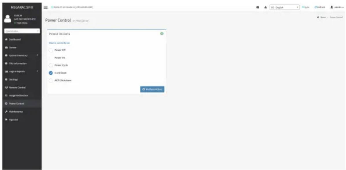
text_image
MEGARAC SP-X 12.01.20 MAY'S 2023 PROGRESS FILE Hot Online Quick Online... Dashboard Server Syncmail Inventory File Information Logic & Resources Settings Remode Control Intelligent Hardware Power Control Maintenance Sign out Power Control in Main Server Power Actions Find it currently on Power Off Power Die Power Cycle Hard Reset ACR Shutdown Patterns Action Name: Power ControlThe setting options of Power Control are explained below.
Power Off: Powers off the server immediately.
Power On: Powers on the server.
Power Cycle: This option will first power off, and then reboot the system (cold boot).
Hard Reset: This option will reboot the system without powering off (warm boot).
ACPI Shutdown: Initiates operating system shutdown prior to the shutdown.
Perform Action: Performs the selected operation.
Procedure
Select an action and click Perform Action to proceed with the selected action.

Note: During Execution you will be asked to confirm your choice. Upon confirmation, you be informed about the status after few minutes.

Note: It is advisable to use Chrome or IE for H5Viewer, since Firefox has its own memory limitations.
2-10 Maintenance Group
The Maintenance Group page allows you to do maintenance tasks on the device. To open the Maintenance Group page, click Maintenance Group from the menu bar.
Maintenance Group contains the following items:
- Backup Configuration
- Firmware Image Location
- Firmware Information
- Firmware Update
- Preserve Configuration
- Restore Configuration
- Restore Factory Defaults
- System Administrator
A sample screenshot of Maintenance Group is shown below.
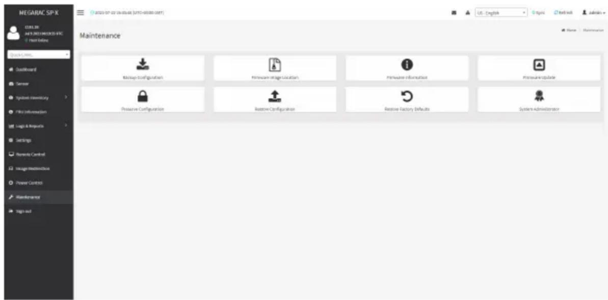
text_image
MEGARAC SP-X C:\10.3\2019\MEGARAC SP-X File Online Quick Links... Defaultboard Sensor Syncbase inventory File Information Logic & Impacts Settings Nintendo Control Usage Monitoring Power Control Maintenance Sign out Maintenance Backup Configuration Hardware Installation Location Hardware Information Pressure Update Pressure Configuration Restore Configuration Restore Factory Defaults System Administrator2-10-1 Backup Configuration
This page allows you to select the specific configuration items to be backed up in case of "Backup Configuration".
To open the Backup Configuration page, click Maintenance > Backup Configuration from the menu bar. A sample screenshot of Backup Configuration page is shown below.

text_image
MEGARAC SP-X MAGUIR Any SIMI-MARKS-SPX Use Existing Quick Loans... Dashboard Server Systems inventory File information Logic & Impacts Settings Remode Control Intage/Media/Cloud Power Control Maintenance Sign out Backup Configuration Check All Sleep XMI Network & Network Video ATP Authentication SPS/SH ExerciseThe fields in the Backup Configuration page are explained below.
Check All: Selects all setting options.
Download: Downloads and saves the configuration files backup from BMC to client system.
Procedure
- Click Check All to back up all setting option or check individual setting option to back up the selected items.
- Click Download to save the backup file to the client system.
2-10-2 Firmware Image Location
This page is used to configure firmware image into the BMC.
To open the Firmware Image Location page, click Maintenance > Firmware Image Location from the menu bar. A sample screenshot of Firmware Image Location page is shown below.

text_image
MEGARAC SP-X 12.03.28 M/F5 (NEE1) (NEE2) (NEE) Next Online QuickInfo... Dashboard Server Synbase inventory File information Tags & Requests Settings Bremode Control Image-Redictionbox Power Control Maintenance Sign out Firmware Image Location Image Location Type With typing during Read FTP Server STTP Server Address Requested, if FTP is available STTP Image Name Requested, if FTP is available FTP Ready Command E Save Home Subsequence Pressure Image LocationThe fields in the Firmware Image Location page are explained below.
Image Location Type: Type of location to transfer the firmware image into the BMC either Web Upload during Flash or TFTP Server.
TFTP Server Address: Address of the server where the firmware image is stored.

Note: The Server supports both IPv4 and IPv6 addresses
TP Address made of 4 numbers separated by dots as in "xxx.xxx.xxx.xxx".
Each number ranges from 0 to 255.
First number must not be 0.
IPv6 Address made of 8 groups of 4 Hexadecimal digits separated by colon as in "xxxx:xxxx:xxxx:xxxx:xxxx:xxxx:xxxx:xxxx."
Hexadecimal digits are expressed as lower-case letters.
TFTP Image Name: Full Source path with filename of the firmware image is stored on TFTP Server.
TFTP Retry Count: Number of times to be retried in case a transfer failure occurs. Retry count ranges from 0 to 255.
Save: Saves the configured settings.
Procedure
- Select the Image Location Type (Web Upload during flash / TFTP Server).
- If the protocol selected is TFTP, enter the IP address of the server in the TFTP Server Address field.
- Enter the TFTP Image Name in the given field
- Enter the TFTP Retry Count value.
- Click Save to save the changes.
2-10-3 Firmware Information
To open the Firmware Information page, click Maintenance > Firmware Information from the menu bar. A sample screenshot of the Firmware Information page is shown below.

text_image
MEGARAC SP-X LEAVLR M&S 2021 MEGARAC SP-X Host Online Quick Links... Outboard Sensor Systems Inventory GUI Information Log & Reports Settings Genade Control Image Coordination Power Control Maintenance Sign out Firmware Information BMC Firmware Information Act/Iter: Notagh ID Build Date 2019-2021 Build Time: 06:30:25 UTC Firmware version: 12.01.2W BIOS Firmware Information Product Manufacturer 04/08/TE Product Maker P132-AK1-OR Build Date P132-06/01 Firmware version: FH CPLD Firmware Information Firmware version: MS 21 Location 1.12The fields in the Firmware Information page explained below.
BMC Firmware Information
Active Image ID: Displays the active image ID.
Build Date: Displays the build date of the active BMC image.
Build Time: Displays the build time of the active BMC image.
Firmware version: Displays the firmware version of the active BMC image.
BIOS Firmware Information
Product Manufacturer: Displays the hardware manufacturer.
Product Name: Displays the model name of the device.
Build Date: Displays the build date of the device.
Firmware version: Displays the BIOS version installed on the device.
CPLD Firmware Information
Firmware version: Displays the CPLD Firmware version.
2-10-4 Firmware Update
To open the Firmware Update page, click Maintenance > Firmware Update from the menu bar. The update wizard will take you through the update process. A reset of the box will automatically follow if the upgrade is completed or cancelled. An option to Preserve All Configuration is available; enable it, if you wish to preserve already configured settings through the upgrade.

Warning: Please note that after entering the update mode wizard, other web pages and services will not work. All open widgets will be closed automatically. If the upgrade process is cancelled in the middle of the wizard, the device will be reset.

Note: The firmware upgrade process is a crucial operation. Make sure that the chances power or connectivity loss are minimal when performing this operation.
Once you enter into Update Mode and choose to cancel the firmware flash operation, the BMC must be reset. This means that you must close the Internet browser and log back onto the BMC before you can perform any other types of operations.
Once Firmware upgrade using web is started, the regular IPMI command will not be allowed for safety concern if Enable IPMI Command handling during flashing support is disabled in project configuration.
Sample screenshots of Firmware Update are shown below.
BMC Update
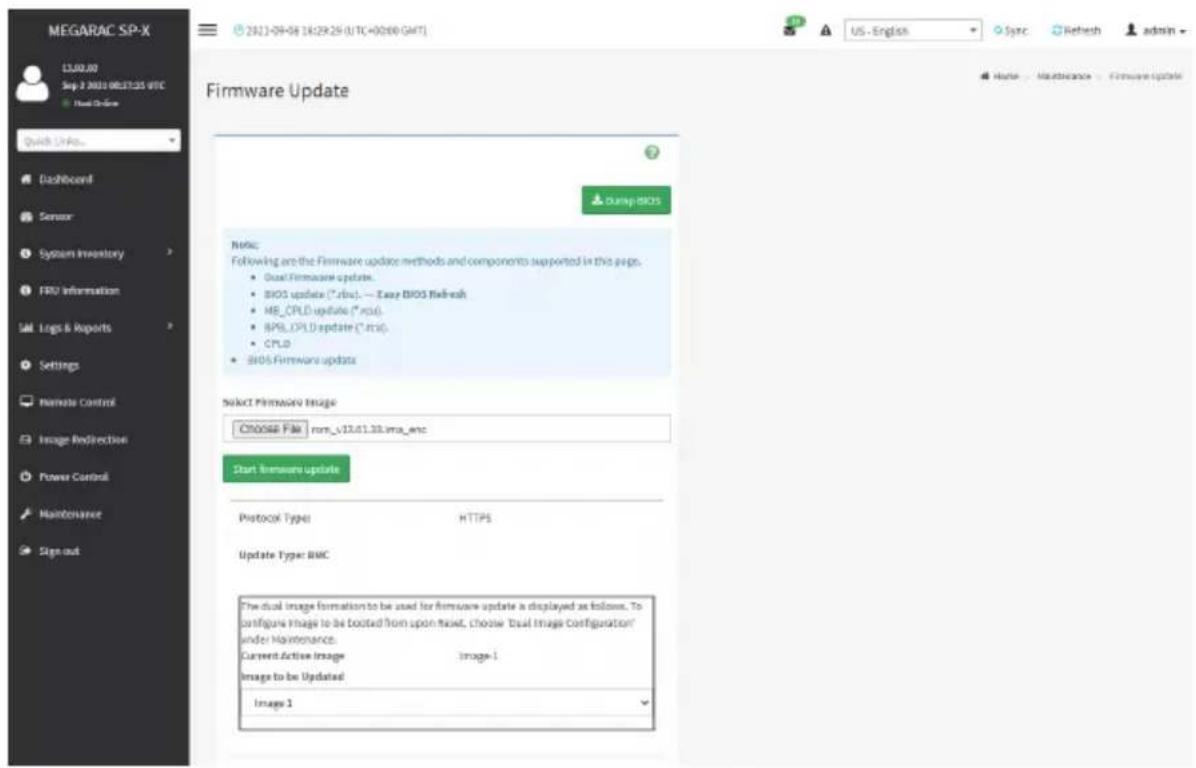
text_image
MEGARAC SP-X 13.00.00 Sep 2 2020 08.27.25 UTC Default Online Quick Links... Dashboard Sensor System Inventory FRU Information Logs & Reports Settings Remote Control Image Redirection Power Control Maintenance Sign out Firmware Update Damp BIOS Note: Following are the Firmware update methods and components supported in this page. • Dual Firmware update. • BIOS update (*.rbc). — Easy BIOS Refresh • MB_CPLD update (*.rbc) • BPS_CPLD update (*.rbc) • CPLD • BIOS Firmware update Select Firmware Image Choose File : non_v13.01.33.xma_enc Start firmware update Protocol Type: HTTPS Update Type: BMC The dual image formation to be used for firmware update is displayed as follows. To configure Image to be booted from upon reset, choose 'Dual Image Configuration' under Maintenance. Current Active Image Image-1 Image to be Updated Image 1 US - English Sync Refresh admin Home Maintenance Firmware UpdateBIOS Update

text_image
MEGARAC SP-X 13.09.00 Sep 2, 2021 08/17:56 GMT Host Online Quick Links... Dashboard Server System Inventory TRU Information Logs & Reports Settings Remote Control Image Redirection Power Control Maintenance Sign out Firmware Update Dump BIOS Note: Following are the Firmware update methods and components supported in this page. • Dual Firmware update. • BIOS update (*.rbs). — Easy BIOS Refresh • MD_CPLD update (*.rdu). • BPS_CPLD update (*.tcs). • CPLD • BIOS Firmware update Select Firmware Image Choose File Image.RSU Start firmware update Protocol Type: HTTPS Update Type: BIOS select BIOS BIO51 BIO52 US - English Sync Refresh admin Home Maintenance Firmware UpdateThe fields in the Firmware Update page are explained below.
Dump BIOS: Click to dump the current BIOS image.
Choose File: Selects the firmware image to be uploaded.

Note:
If you select a BIOS file to be uploaded, you need to select BIOS1 or BIOS2 in the select BIOS field.
If you select a BMC image to be uploaded, you need to select Image 1 or Image 2 in the drop-down list.
Start firmware update: Starts the firmware update.
Procedure
- Click Select Firmware Image to select the firmware image to be uploaded.
- Click Start firmware update to proceed.
- Click Preserve all Configuration if you want to preserve all configuration settings during the firmware update and then click Proceed to Flash at the bottom to proceed.

text_image
Sign outProtocol Type:
HTTPS
Update Type: BMC
☐ Preserve all Configuration. This will preserve all the configuration settings during the firmware update - irrespective of the individual items marked as preserve/overwrite in the table below.
All configuration items below will be preserved as default during the restore configuration operation. Click "Edit Preserve Configuration" to modify the Preserve status settings.
Edit Preserve Configuration
| S.No | Preserve Configuration Item | Preserve Status |
| 1 | SDR | Overwrite |
| 2 | FRU | Overwrite |
| 3 | SEL | Overwrite |
| 4 | IPMI | Overwrite |
| 5 | NETWORK | Overwrite |
| 6 | NTP | Overwrite |
| 7 | SNMP | Overwrite |
| 8 | SSH | Overwrite |
| 9 | KYM | Overwrite |
| 10 | AUTHENTICATION | Overwrite |
| 11 | SYSLDG | Overwrite |
| 12 | WEB | Overwrite |
| 13 | REDFISH | Overwrite |
Proceed to Flash
WARNING: Please note that after entering the update mode, the widgets, other web pages and services will not work. All the open widgets will be automatically closed. If the upgradation is cancelled in the middle of the wizard, the device will be reset only for BMC BOOT, and APP components of Firmware.
- When the message requesting your confirmation prompts, click OK to proceed. The BMC will begin to verify and upload the firmware.
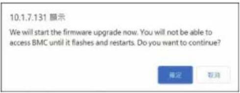
text_image
10.1.7.131 顯示 We will start the firmware upgrade now. You will not be able to access BMC until it flashes and restarts. Do you want to continue? 確定 取消- When the firmware is uploaded completely, check Full Flash in the Section Based Firmware Update field and then click Flash selected sections.

Note: If you only want to update the firmware for certain sections, check the Upgradable/Non-Upgradable box for the individual sections instead of checking Full Flash.

natural_image
Solid dark gray rectangle with no visible text, symbols, or features.Section Based Firmware Update
All the module section versions in the existing image and uploaded
image are the same.
Version Compare Flash

Full Flash
Section
Name
Existing
version
Uploaded
version
Upgradable/Non-
Upgradable
boot
conf
13.1.000000
conf
13.1.000000
ec
1.17.000000
dtb
13.1.000000
root
13.1.000000
osimage
13.1.000000
www
13.1.000000
testapps
13.1.000000
dre
13.1.000000
ast2600e
13.1.19
13.1.000000
13.1.000000
13.1.000000
1.17.000010
13.1.000000
13.1.000000
13.1.000000
13.1.000000
13.1.000010
13.1.000000
11.1.33
Flash selected sections
Uptrading 100%
WARNING: Please note that after entering the update mode, the widgets, other web pages and services will not work. All the open widgets will be automatically closed. If the upgrading is cancelled in the middle of the wizard, the device will be reset only for BMC BOOT, and APP components of Firmware.
- When the message requesting your confirmation prompts, click OK. The BMC will start updating the firmware.
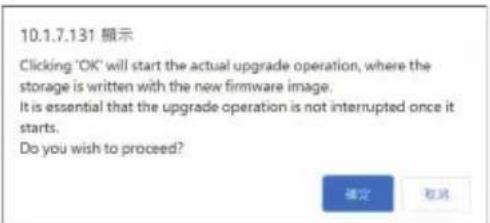
text_image
10.1.7.131 顯示 Clicking 'OK' will start the actual upgrade operation, where the storage is written with the new firmware image. It is essential that the upgrade operation is not interrupted once it starts. Do you wish to proceed? 確定 取消- A confirmation message will appear once the firmware has been successfully updated. Click OK to proceed.
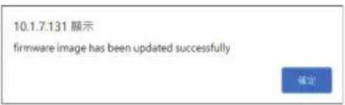
text_image
10.1.7.131 顯示 firmware image has been updated successfully 確定- Click OK. The BMC will close all sessions displayed on the screen and automatically reboot the system.
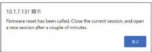
text_image
10.1.7.131 顯示 Firmware reset has been called. Close the current session, and open a new session after a couple of minutes.2-10-5 Preserve Configuration
Preserve Configuration allows users to preserve the existing configuration so that the current configurations on the BMC will not be overwritten during the firmware update process.
To open the Preserve Configuration page, click Maintenance > Preserve Configuration from the menu bar. A sample screenshot of the Preserve Configuration page is shown below.

text_image
MEGARAC SP-X 12.01.38 AVS 2021.MEGRAC SP-X File Online Quick Links... Dashboard Camera Zygkin Inventory File Information Logic & Resources Settings Remode Control Insight Realdehyde Power Control Maintenance Tag out Preserve Configuration Click here to go to Firmware Update or Recess Factory Defaults check All SDR FBS NEL iFree Network NTF SMADP SSH WNT Authentication Spiring Vitch Redfish USE - English APIs Network Admins Name - Maintenance - Purpose ConfigurationThe fields in the Preserve Configuration page are explained below.
Check All: Selects all items.
Save: Saves the changes.

Note: This configuration is used by Restore Factory Defaults process.
SDR
Following files will be preserved:
SDR.dat: This file contains the sensor data record information that is used in IPMI.
Dependency Configurations - NIL
FRU
Following files will be preserved:
FRU.bin: This file contains the logical field replaceable unit data that are used by IPMI.
Dependency Configurations - SDR
SEL
Following files will be preserved when Delete SEL reclaim space is disabled:
SEL.dat: This file contains the system event logs that are being logged by the IPMI.
Following files will be preserved when Delete SEL reclaim space is enabled:
Selreclaiminfo.ini - The file contains the SEL repository information.
SEL folder - This folder contains the multiple files of event logs.
Dependency Configurations - IPMI
IPMI
The following files are preserved in IPMI configuration:
IPMI.conf: This file contains the IPMI configurations such as SEL rep size, SDR rep size, interface specific, enable/disable, Primary/Secondary, IPMB Bus number etc.
Dependency Configurations - NIL
Network
To save network settings related with IPMI (LAN IP or DHCP configuration), select "IPMI" and "Network" options simultaneously. After restore configuration, the Network Configuration will be preserved successfully. Following files will also be preserved:
dhcp.conf: This file is to configure the host name in the FQDN format.
dns.conf: This file is used to configure the DNS registration method and DNS server for the particular interface, hostname: This file is used to store the Hostname of the BMC.
hostname.conf: This file is used to configure the host name creation method Manual/Automatic for the BMC.
Vlaninterfaces: This file helps to enable the vlan interface for the particular LAN interface
vlansetting.conf: This file is to store the vlan ID and Vlan priority for the particular VLAN interface entry.
bond.conf: This file is to enable the bond interface for the specified LAN interfaces.
Interfaces: This file is to configure the IP/IPV6 addresses for the LAN interface using static/DHCP method.
activeslave.conf: This file is to configure the active interface for the specified bond interface.
This file depends on bond.conf.
hosts: This file is used to store the host name to map the IP address.
hosts.allow: This file contains the list of hosts that has permission to access the system
hosts.deny: This file contains the list of host that does not allow accessing the system
resolv.conf: This file is used to store the nameserver and domain name for hostname registration.
dhcp6c-script: This file is used to configure the domain name, DNS server IPv6 address and NTP address.
dhcp6c.conf: This file is to configure the IPv6 parameters for the DHCPv6 clients.
ncsicfg.conf: This file is to configure the NCSI related configurations.
nsupdate.conf: This file is to configure the channel ID, package ID for the NCSI interface.
phycfg.conf: This file is to configure the link speed, duplex and MTU value for the specified interface.
dhcp.preip_4: This file is to store the pre IPv4 address. This file will be created at runtime.
dns.conf: This file is used to configure the DNS registration method and DNS server for the particular interface.
hostname: This file is used to store the Hostname of the BMC.
hostname.conf: This file is used to configure the host name creation method Manual/Automatic for the BMC.
Vlaninterfaces: This file helps to enable the vlan interface for the particular LAN interface
vlansetting.conf: This file is to store the vlan ID and Vlan priority for the particular VLAN interface entry.
bond.conf: This file is to enable the bond interface for the specified LAN interfaces.
Interfaces: This file is to configure the IP/IPV6 addresses for the LAN interface using static/DHCP method.
activeslave.conf: This file is to configure the active interface for the specified bond interface. This file depends on bond.conf.
hosts: This file is used to store the host name to map the IP address.
hosts.allow: This file contains the list of hosts that has permission to access the system
hosts.deny: This file contains the list of host that does not allow accessing the system
resolv.conf: This file is used to store the nameserver and domain name for hostname registration.
dhcp6c-script: This file is used to configure the domain name, DNS server IPv6 address and NTP address.
dhcp6c.conf: This file is to configure the IPv6 parameters for the DHCPv6 clients.
ncsicfg.conf: This file is to configure the NCSI related configurations.
nsupdate.conf: This file is to configure the channel ID, package ID for the NCSI interface.
phycfg.conf: This file is to configure the link speed, duplex and MTU value for the specified interface.
dhcp.preip_4: This file is to store the pre IPv4 address. This file will be created at runtime.
NTP
Following files will be preserved:
ntp.conf: This file contains the NTP dameon protocol configuration parameters such as synchronization sources, nodes and other related information
ntp.stat: This file contains the auto or manual network type protocols
adjtime: This file contains the time to synchronize the system clock
Localtime: This file is the system link to the file local time or to the correct time zone in the system timezone directly.
Dependency Configurations - IPMI
SNMP
Following files will be preserved:
snmp_users.conf: This file contains the SNMP user configurations such as user name and password encryption mechanism for the specific users.
snmpcfg.conf: This file contains the SNMP users privilege levels such as ro user and rw user.
Dependency Configurations - NIL
SSH
Following files will be preserved:
sshd_config: This file contains the keyword argument pairs of configurations such as Address family, Accept Env, Allow, users, authorized key files etc.
ssh_host_dsa_key, ssh_host_rsa_key: These files contain the private parts of the host keys.
ssh_host_dsa_key.pub, ssh_host_rsa_key.pub: These files contain the public parts of the host keys.
Dependency Configurations - NIL
KVM
Following files will be preserved:
vmedia.conf: This file contains the modes of media such as cd,fd,hd and enable and disable flags for lmedia, rmedia and sd servers.
stunnel.conf: This file contains the information about the stunnel configuration. It will also contain advisor and media server's secure port if secure connection is enabled.
usermacro.conf: This file saves the user defined macro from the jviewer.
rmedia.conf: This file contains the image name and the remote machine information like IP address, user name, password, domain name and share type.
Dependency Configurations - NIL
Authentication
Following files will be preserved:
activatedir.conf: This file contains the configurations such as sslenable, timeout, racdomain, adtype, adfilterdc1, adfilterdc2, adfilterdc3, username, password, and rolegroup information such as name domain and privileges.
openLdapGroup.conf: This file contains the oprnm ldap role group information such as name domain and privilege.
nsswitch.conf: This file contains the sources to obtain the name service information in the range of categories and in what order
pam_withunix: This file contains the PAM Order of modules such as IPMI, LDAP, RADIUS and UNIX.
pam_wounix: This contains the PAM Order of modules such as IPMI, LDAP and RADIUS.
group: This file contains the Linux group. It stores the group information or defines the user group information in Linux.
passwd: This file contains the user login information for the Linux system
shadow: This file contains the encrypted password information for the clients.
ldap.conf: This file contains the ldap server configuration details such as bindn, binpw, pam_password, nss_reconnect_tries, port, port secondary, host, host secondary.
radius.conf: This file contains the radius server IP address, port number, secret, timeout, privilege etc.
Dependency Configurations – NIL
Syslog
System Event Log
Web
Web Settings
Extlog
Audit Log & System Log
Redish
Redfish Audit Log
Procedure
- Click Firmware Update or Restore Configuration to open the Firmware Update or Restore Configuration page accordingly.
- Select Check All or the individual configuration items you want to preserve.
- Click Save to save the changes.
2-10-6 Restore Configuration
This page allows you to restore the backup configuration files from the client system to the BMC. To open the Restore Configuration page, click Maintenance >Restore Configuration from the menu bar. A sample screenshot of the Restore Configuration page is shown below.
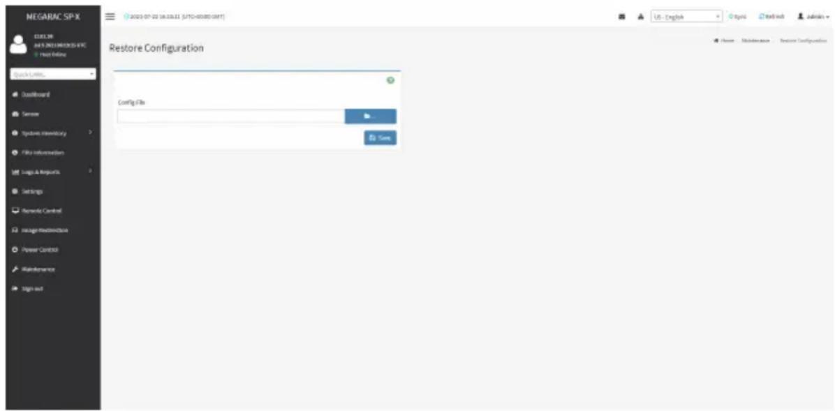
text_image
NEGARAC SP-X COLOR JUL 2021 NEWSPX5-8 FRC Host Online Quick Links... Defaultboard Sensor Systems Inventory File Information Logic & Network Settings Remarks Control Image Resources Power Control Maintenance Sign out Restore Configuration Config File Save USE - English Organic Mail switch Admins Home Maintenance Restore ConfigurationThe fields in the Restore Configuration page are explained below.
Config File: Select the file which was backup earlier.
Save: Confirms to upload the selected configuration file.
Procedure
- Click Browse to search for the previously saved configuration file.
- Click Save. A warning message will appear on the screen.

text_image
10.1.112.37 says: Click OK if you want to continue restoring configuraions WARNING:Restoring configurations will restart the device OK Cancel- Click OK to upload the new configuration file and the device will restart automatically.
2-10-7 Restore Factory Defaults
Restore Factory Defaults lists the configuration items that can be preserved during the restore process.

Warning: Please note that after entering restore factory widgets, all other web pages services will not work. All active widgets will be closed automatically. The device will and reboot within few minutes.
To open the Restore Factory Defaults page, click Maintenance >Restore Factory Defaults from the menu bar. A sample screenshot of the Restore Factory Defaults page is shown below.

text_image
NEGARAC SP-X 12.01.30 NPS NEGARAC SP-X Host Online Quick Links... Dashboard Sensor Hybridging Inventory File Information Logic & Resources Settings Remode Control Usage Hardware Power Control Maintenance Sign out Restore Factory Defaults The following checked configurations will be presented through the restore operation. You can make changes to the tip in the reserve configuration page. SER FPU NEL IPMD Network NTP SMH0 SSH KVM Authentication Spiking Web Redfish USE - English Organic Networks Adminals Home - Maintenance - Reserve Factory DefaultsProcedure
- Click Preserve Configuration to open the Preserve Configuration page, which is used to preserve the particular configuration so that the configuration will not be overwritten by the default configuration.
- Select the individual configuration items you want to preserve.
- Click Save to save the changes.
2-10-8 System Administrator
This page is used to configure the System Administrator settings.
To open the System Administrator page, click Maintenance > System Administrator from the menu bar. A sample screenshot of the System Administrator page is shown below.

text_image
MEGARAC SP-X URL: 2019-03-22 UK 2.2.61 (UFC-40380.047) User Interface Squark CAMEL Lastboard Server Symbol Inventory File Information Logic & Requests Settings Remode Control Image Maintenance Power Control Maintenance Sign out System Administrator User Name: system: Available User Accounts Change Password Password: Confirm Password StartThe fields in the System Administrator page are explained below.
Username: Displays user name of System Administrator. It is read-only.
Enable User Access: Enables user access for system administrator.
Change Password: Allows users to change the password.

Note: This field will not allow more than 64 characters.
Password must be at least 8 characters long and blank space is not allowed.
Save: Saves the new configuration for system administrator.
Procedure
- Check Enable User Access to enable user access for system administrator.
- Enable Change Password. This action enables the password fields.
- Enter the password in the Password field.
- Re-enter the password in the Confirm Password field.
- Click Save to save the changes.
2-10-9 Sign Out
To log out from the Web GUI, click the admin on the top right corner of the screen. A sample screenshot of admin option is shown below.
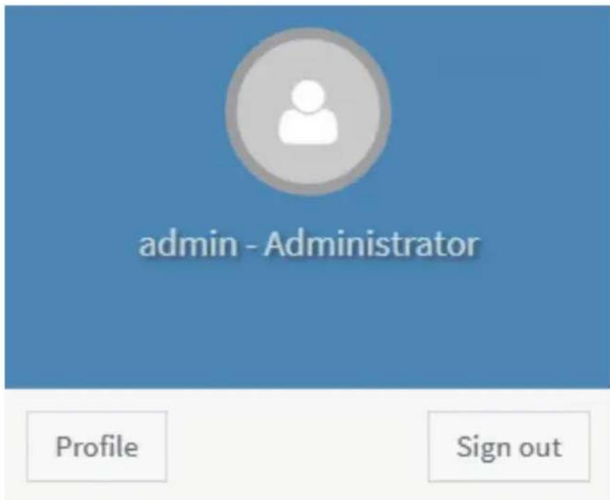
text_image
admin - Administrator Profile Sign outClick Sign Out to perform log out from the Web GUI. A Warning message will be prompted you to proceed further, click OK to log out else Cancel to retain the Web GUI.