CF 4040RBINF - Cooker ROSIERES - Free user manual and instructions
Find the device manual for free CF 4040RBINF ROSIERES in PDF.

User questions about CF 4040RBINF ROSIERES
0 question about this device. Answer the ones you know or ask your own.
Ask a new question about this device
Download the instructions for your Cooker in PDF format for free! Find your manual CF 4040RBINF - ROSIERES and take your electronic device back in hand. On this page are published all the documents necessary for the use of your device. CF 4040RBINF by ROSIERES.
USER MANUAL CF 4040RBINF ROSIERES
1 - Hot plate burner 4,5 kW - "Cast-iron hot plate" or "Griddle"
2 - Fast burner, 2,5 kW, back left
3 - Semi fast burner, 1,45 kW, front left
4 - Ultra-fast burner, 3,5 kW, back right
5 - Fast burner, 2,5 kW, front right
6 - Push-button ignitor for gas burners and cast-iron hot plate
7 - Push-button for oven interior lights
8 - Natural convection oven with slide-out catalytic liner
9 - Right oven thermostat control knob
10 - Multifunction oven, normal enamel
11 - Fan cooking push-button (left oven)
12 - Left oven control knob
13 - Left oven indicator light
14 - Power-on oven indicator light
15 - Right oven indicator light
As part of our ongoing commitment to continually improve product quality, ROSIERES may carry out modifications linked to technical improvements.

Appliance meeting with the standard 89/336/EE, 73/23/CEE and 90/396/CEE.
TECHNICAL DATA
Dimensions of the appliance (In cm) Dimensions of the appliance (In cm)
Width : 119,5
Depth : 60
Height with back panel : 95 - Height without back panel : 84
THE HOBTHE HOB
Right hand side Right hand side
Left hand sideLeft hand side
1 semi-fast burner 1,45 kW 1 cast-iron plate 4,5 kW
2 fast burners 2,5 kW
1 ultra-Fast 3,5 kW
Gases to be used in accordance with adjustments : Gases to be used in Natural gas - Butane gas - Propane gas Natural gas - Butane gas -
THE OVENS
| Usable oven dimensions : | multifunction | natural convection |
| Width | 42,5 cm | 41,5 cm |
| Depth | 38 cm | 35,5 cm |
| Height | 29,5 cm | 28,5 cm |
| Usable oven | 47 litres | 41 litres |
Ovens Powers (kW)Ovens Powers (kW)
Multifunction oven
Fan oven : 2,42 kW
Natural convection : 2,39 kW
Grill : 2,11 kW
Natural convection oven 2,39 kW
Grill : 2,11 kW
Ovens Consumptions Ovens Consumptions
Multifunction oven
to reach 175°C 0,4 kWh
to hold at 175°C for 1 h 0,5 kWh
Total 0,9 kWh
Natural convection oven
to reach 200°C 0,4 kWh
to hold at 200°C for 1 h 0,5 kWh
Total 0,9 kWh
text_image
OFF FULL OPEN LOW HEATEach burner is controlled by a progressive regulation tap which allows a longer and more precise range of adjustment, from the maximum position to the lowest flame.
IGNITING THE BURNER : a symbol next to each control knob indicates which burner is being used.
. Turn on the gas supply tap.
. Push and turn the control knob to the left until the high flame.
. Press the switch "6" to ignite the burners.
. Regulate the flame according to the speed required for cooking, and to the pan diameter.
. To stop the flame, turn the knob until the stop position "•".
NB :NBor some reason there is no electrical power, the burners can be ignited with a lighter, when the burner knob is pushed in and turned to the large flame symbol.
THE VARIOUS BURNERS: THE VARIOUS BURNERS areent dimensions. You should be aware of the differences in power of each burner.
. Use the most powerful burner to boil liquids, to cook grilled steaks and generally all foods that must be cooked quickly.
. Use the intermediate burner for stews and sauces.
. Use the small burner for small pans.
THE CHOICE OF PANS :THE CHOICE OF PANS :
. Pans with curved, ridged or warped bottoms are not recommended.
. To save gas, make sure that the flames do not overlap the bottom of the pan.
. Avoid boiling food too intensely. Food is not cooked any quicker this way. In fact, it is subjected to severe agitation, which may cause the food to lose some of its flavour.
THE CAST-TRICASATION PLA
The cast-iron plate is controlled by a thermocouple safety device which automatically cuts off the gas supply if the flame is accidentally extinguished.
IGNITING THE CAST-IRON PLATE :IGNITING THE CAST-IRON PLATE :
. Push and turn the control knob to the left, and simultaneously, press the ignition button "6", keeping the knob pushed in for a few seconds. The ignition sparks and engages the safety system when the flame is ignited.
USE : USE :
The cast-iron burner enables you to use large cooking pans or to cook several dishes at the same time. It is more powerful than a normal gas burner and allows you:
- to simmer for long periods without having to watch the food,
- to keep food hot without burning it,
- to prepare special sauces without using a "bain-marie" ...
- Steak gridle.- Steak gridle.
- Left open for Wok cooking.
Depending on the dish that you are preparing, you can either adjust the burner or change the position of the cooking vessel on the cast-iron plate, the centre being the hottest, and cooler areas nearer the outer edges.
BAKING / ROKSTONGFASTING
• Always keep small children away from the oven while it is in use.
use both upper and lower heating elements, but no fan.
This function is available on the two ovens.
With this method of cooking the heat naturally rises, therefore the higher shelf positions are hotter than the lower ones. So it is possible, for instance to cook a casserole or braise vegetables on a low shelf, while cooking pastry dishes or baking potatoes on a higher shelf. This method of cooking is often preferred by the cook, who likes to braise casseroles in thick earthenware dishes, or bake puddings slowly and gently. The results of this method may be preferred as crusts on baked dishes are often browner and crisper.
The best results using a conventional oven are achieved when cooking on one shelf only. If you are using more than one shelf, tins will probably need changing halfway through the cooking time. Unless a recipe indicates otherwise, use a middle shelf position in the oven when cooking on one level only.
- Turn the thermostat control knob to the required temperature for your cooking, between 60°C and 280°C. cooking, between 60°C and 280°C.
The power-on indicator light comes on when the oven is working and remains on for the whole duration of the cooking time.
The oven indicator light shows that the thermostat function has been selected. It goes on and off regularly during cooking.
natural_image
Pure architectural line drawing of a room with shelves and a central staircase (no text or symbols)PRE-HEATING TIME :
- 20 minutes between 250 and 280°C
- 15 minutes between 150 and 220°C
- 10 minutes between 60 and 120°C.
Place the food to be cooked Place the food to be cooked in the centre of the oven. in the centre of the oven.
BAKING / RQKSTONGFASTING
| sdooF | y temperature | gnikooC time | gnikooC | nov noitiso | |
| Whole fish, roasted or braised | |||||
| Fish | 1 kg | 200 / 220 | 20' | 1 | |
| Meat vegetables | |||||
| Duck | 1,5 kg | 200 / 220 | 1 h 30 | 1 | |
| Braised cabbage | 6 pers. | 200 / 220 | 1 h approx. | 1 | |
| Leeks | 6 pers. | 200 / 220 | 1 h approx. | 1 | |
| Leg of lamb | 200 / 220 | 15' p/kilo | 1 | ||
| Goose turkey | 7 kg | 160 / 180 | 2 h 30 - 3 h | 1 | |
| Pies | 200 / 220 | 1 hour for 1 kg | 1 | ||
| Roast chicken | 1 / 1kg 200 | 200 / 220 | 45' - 1 hour | 1 | |
| atrovaS | 6Ø2 ep | 200 / 220 | 40 / 50' | 1 | |
| Roast beef | 230 / 240 | 15 min p/pound | 1 | ||
| Desserts | |||||
| Sponge cake | 1 kg 500 | 180 / 200 | 50 / 60' | 1 | |
| kædér | 6Ø2 ep | 200 / 220 | 40 / 45' | 1 | |
| Crème caramel | adin nitre | 0809 | '54 in double boiler | 1 | |
| Choux pastry | 200 | 40' | 3 | ||
| Crumbly biscuit | 1 kg 500 | 200 / 220 | 45' / 1 hour | 1 | |
FAN OXAENOVEN
- The oven doors are hot when they are on, keep young children away.

FAN OVEN : (FAN OVEN Only)
simultaneous operation of the upper and lower elements and the fan, which circulates air round the inside of the oven.
Because the temperature is uniform inside the oven cavity there will be no problems when the oven is filled to maximum capacity with various dishes, allowing you to save time and energy. Batch baking is recommended.
- Depress the fan button "11" Ⓜ. Depress the fan button "11"
- Turn the thermostat control knob to a temperature between 60 and 240°C.240°C.
When cooking with a fan oven it is generally recommended that you use lower temperatures and reduced times. This is because the circulating air in a fan oven is very intense, ensuring that the heat penetrates the food more rapidly than in a conventional oven. This means the food will cook faster. When cooking for the first time it is advisable to cook at a lower temperature, than to cook, for example, a cake too quickly so that it browns before it is cooked through.
The power-on indicator light comes on when the oven is working and remains on for the whole duration of the cooking time.
The oven indicator light shows that the thermostat function has been selected. It goes on and off regularly during cooking.
PRE-HEATING TIME :
- 20 minutes between 210 and 240°C
- 15 minutes between 120 and 180°C
- 10 minutes between 50 and 90°C.
FAN OXENOVEN
| sdooF | y gnikooC erutarepnte | gnikooC itme | Oven noitiso | |
| Whole fish, roasted or braised | ||||
| Fish | 1 kg | 200 / 220 | 20' | 1 |
| Meat vegetableselbageM | ||||
| Duck | 1,5 kg | 200 / 220 | 1 h 30 | 1 |
| Braised cabbage | 6 pers. | 200 / 220 | 1 h approx. | 1 |
| Leeks | 6 pers. | 200 / 220 | 1 h approx. | 1 |
| Leg of lamb | 200 / 220 | 15' p/kilo | 1 | |
| Goose turkey | 7 kg | 160 / 180 | 2 h 30 - 3 h | 1 |
| Pies | 200 / 220 | 1 hour for 1 kg | 1 | |
| Roast chicken | 1 / 1kg 200 | 200 / 220 | 45' - 1 hour | 1 |
| ratyouaS | ∅27 rep | 200 / 220 | 40 / 50' | 1 |
| Roast beef | 230 / 240 | 15 min p/pound | 1 | |
| Dessertede | ||||
| Sponge cake | 1 kg 500 | 180 / 200 | 50 / 60' | 1 |
| kæturF | ∅27 rep | 200 / 220 | 40 / 45' | 1 |
| Crème caramel | aludividn mæk | 0980 | '54 in double boiler | 1 |
| Choux pastry | 200 | 40' | 3 | |
| Crumbly biscuit | 1 kg 500 | 200 / 220 | 45' / 1 hour | 1 |
THE GRILLTHE GRILL
Warning : when grilling, parts of the oven can become very hot. Keep young children away.away.
COOKING WITH THE GRILL SHOULD BE CARRIEDCOOKING WITH THE GRILL OUT WITH THE DOOR OPEN OR LIGHTLY AJAR,OUT WITH THE DOOR OPEN WITH THE HEAT DEFLECTOR FITTED.WITH THE HEAT DEFLECTOR FITTED
THE GRILL :THE GRILL :
During grilling, only the upper heating element is operational.
Grilling is a healthier method of cooking meat and fish than frying.
It is a fast method of cooking, using direct heat, therefore only the best cuts of meat should be grilled. Times for grilling can be varied by altering the position of the food in the oven.
Preheating the oven is required until the grill element begins to glow.
Using the grill : Using the grill :
♦ Turn the selector control knob to the grill position 🐎.
- Place the shelf at a good height and slide the drip tray into the shelf rails below or place the drip tray directly on the oven base. or place the drip tray directly on
Thin slices of red meat, as well as fish fillets or sliced fish, must be grilled very rapidly and placed as near as possible to the grill. very rapidly and placed a
White meat, pork and vegetables must be placed at a certain distance from the grill; grubking will take longer, but the food will be more tasty.
The power-on indicator light comes on when the oven is working and remains on for the whole duration of the cooking.
The oven indicator light shows that the thermostat function has been selected. It goes on and off regularly during cooking.
"Au Gratin" dishes - To cook "Au gratin" dishes, we recommend beginning with natural convection and followed by grilling.
OVEN ACCESSORIESCESSORIES
A
natural_image
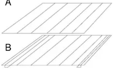
Two identical line drawings of parallel slats labeled A and B, with no text or symbols on the shapes themselves.OVEN SHELVES :OVEN SHELVES :
A : these are for holding dishes and plates.
B : these are for holding meat joints when cooking with the grill. They are fitted with rails into which can be slid the drip tray.
The shelves have a special profile so they always stay horizontal, even when pulled out to the maximum. There is no risk of the dish sliding out or spilling.
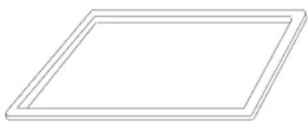
natural_image
Simple 3D rectangular frame outline with no text or symbolsit catches the juices from grilled foods.
Put it onto the shelf, slide it under the rails or put it at the base.
Never use the drip tray as a roasting tray as this willNew create smoke and fat will spatter your oven, becomingcre dirty.dirty.
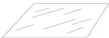
natural_image
Pure geometric lines forming a parallelogram shape without any text, numbers, or symbolsCONFECTIONERY TRAY : CONFECTIONERY TRAY :
this should be placed directly on the shelf. Fairy cakes, meringues and the like can be baked on this tray.
It should be removed from the oven when not in use.
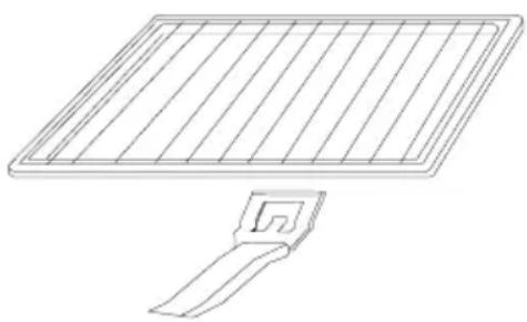
natural_image
Line drawing of a solar panel with grid lines and a handle (no text or symbols)The grill pan, with inner rack, The grill pan, with a shelf rack. Use it for all types of grilling, also as a toaster.
The grill pan has a cool handle so that you can take it without burning yourself. Do not store it inside the oven.
When they are not being used, these accessories should be When they are removed from the oven. removed from the oven.
Use deep dishes made of earthenware. Use deep dishes made of Avoid using glass dishes to cook meat. Avoid using glass dishes
. Allow the cooker and all its components to cool before cleaning.
. Never cover the walls with aluminium foil, the concentrated action of the heat would damage the enamel.damage the enamel.
BURNERS - Clean with soapy water. Make sure that water does not penetrate into the burners. Stubborn stains can be removed with a non-abrasive cream on a sponge. Then dry the burners with a clean cloth.
The burners are not fixed, they can be removed for easy cleaning. Simply wipe them with a cloth wrung out in soapy water. Do not immerse them in cold water immediately after use, as the thermal shock can damage the enamel. Abrasive powders should not be used, as they can scratch the enamel and make it opaque.
If the holes in the burners are blocked with cooking soil, brush with soapy water and dry with a cloth.
Make sure you replace the burners correctly after cleaning.
ENAMELLED PARTS ■ Never use harsh abrasives, scouring pads or sharp objects, as this will cause irreparable damage to the enamel.
Once the cooker has cooled down, simply clean with soapy water and dry with a clean cloth. After each use, clean the enamelled shelves.
THE CAST-IRON PLATE - The plate should be cleaned regularly to keep a good appearance. Cleansers products can be found in shops to take care of the cast-iron polished. You can rubb the plate with a fine emery paper to remove any rust. It should then be wiped over with a cloth impregnated with a light solla light soll
THE OVEN DOOR GLASS - It is recommended to wipe the oven door glass with absorbent paper after each cooking cycle. If there is heavy staining, the glass can be cleaned with a sponge and cleaning agent.
THE STAINLESS STEEL PARTS - To clean the stainless steel parts, use a suitable product available on the market e.g. solvol autosol.
THE DRAWER - Do not store inflammable items or cleaning products in the drawer. Use the drawer only to store cookware. Simply sponge-clean it.
OVEN LIGHTING :
Before starting, the power supply must be disconnected and the plug pulled out.
The lamp and its housing are made of material which can withstand very high temperatures. To change a defective lamp, simply remove the glass housing, replace the lamp by an identical one, and refit the protective glass housing.
Open the door fully and press down slightly.
Engage the clips from the lower hinges onto the spurs on the upper arms as shown in the diagram "a" - carry this out on both the left hand and right hand hinges.
a
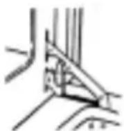
b b
Lift the door assembly upward and outward to disengage it from the oven body - carefully lift the door away from the appliance - do not attempt to release the clips on the hinges whilst the door is disconnected from the appliance. To refit the door, offer it up to the appliance and insert the hinge arms to the slots on the appliance keeping the door parallel to the appliance whilst doing so. The door can be felt to "engage" in the slots and once this is achieved the door can be pressed down slightly and the clips disengaged as in diagram "b", which is the normal position.
CATALYTIC SLIDE OUT BASKET (RIGHT OVEN) CATALYTIC SLIDE OUT BASKET (RIGHT
the oven during cooking. The oven walls are coated with a special enamel whose micro-pores help to burn off fat. Every drop of grease is eliminated by the combination of heat and the catalytic enamel.
REGULAR MAINTENANCE : the accumulation of fine dust, the result of burning off the fat, can in the long term reduce the effectiveness of the enamel.
Also, to get the best results from the enamel, the oven walls should be rinsed with very hot water, after every 15 to 20 cooking cycles.
This light maintenance work is made much easier by the fact that the basket can be completely removed from the oven and washed in the sink. After rinsing and refitting the basket, dry the enamel by heating the oven on maximum for about 15 minutes.
If there has been heavy staining or spillages, the enamel must be cleaned to return it to its original efficiency.
Cleaning is done as follows: wipe up the spillage or big stains with a sponge soaked in very hot water and use a liquid ammonia-based detergent.
- If, after doing this, some stains remain, scrub them with nylon brush.
- then, run the oven for an hour at maximum temperature.
- it is sometimes necessary to repeat this operation several times if the staining is heavy.
NB : if after normal cooking you notice some darkish rings on the walls, do not worry. This is quite normal and means that the grease stains are in the process of elimination.
While the oven is working, the door becomes hot. Keep young children away from it.
THE ENAMEENOVEN (LEFT OVEN)AMENOVEN(SLEET OVEN) with a sponge soaked in a suitable cleaning product and very hot water, in order to remove the most persistent grease stains. If there are very stubborn stains, use the normal commercially available products.
INSTALSATION: TISAFETY INSTRUMENTS"UNSTIONS"
Installing a domestic appliance can be a complicated operation which, if not carried out correctly, can seriously affect consumer safety.
It is for this reason that the task should be undertaken by a professionally qualified person who will carry it out in accordance with the technical regulations in force.
In the event that this advice is ignored and the installation is carried out by an unqualified person, ROSIERES declines all responsibility for any technical failure of the product whether or not it results in damage to goods or injury to individuals.
INSTALLATION : "GAS CONNECTION"
GAS CONNECTIONGAS CONNECTION
These instructions are of partibular interrestion installation particular interest to installer
The cooker is type "X" - "Class 1"; adjoining furniture should not be higher than the level of the cooker hob.
This appliance is not connected to an evacuation device for the products of combustion. It must be installed and connected in compliance with the norms in force in the country of installation. Particular attention should be given to the availability of ventilation. The turnover of air necessary for combustion is a minimum of 2m^3/h per kW of power.
When installing the cooker, it is necessary to provide a 1.5 cm air space on the left side.
Before installing the cooker :ore installing the cooker :
① Make sure that the appliance is compatible. Make the great supply of this
The cooker is pre-set in the factory to work with the type of gas shown on the packaging and on the plate attached to it.
Natural gas (G 20-20 mbar) : mains gas
Butane gas (G 30 28-30 mbar) : supplied in cylinders
Propane gas (G 31 37 mbar) : supplied in cylinders or tanks
② Make the gas connection according to the type of gas to be used.
Based on the gas to be used, choose the appropriate gas connection.
③ If necessary, adapt the cooker for use with another type of gas.
If the cooker is to be used with another type of gas, the cooker must be adapted. The following procedure for adaptation must be followed :
. fit the correct injectors to ensure nominal delivery,
. adjust the appearance of the flame by regulating the air ring,
. adjust the minimum flame of the taps by turning the by-pass screw,
. update the label with the new set up.
Inside the appliance you will find a spanner for removing the injectors, a bag containing the injectors with the relevant table, and some nozzles.
INSTANSTATION: "GAS CONNECTION"
Gas connection should be carried out in compliance with the norms in force in these country of installation. We first installation the use of a suitable flexible connection hose which complies with the regulation currently in force. These will ease installation and any future service operations that may be necessary.
The calorific power or power output and gas pressure will vary according to the gas supply. Burner setting must be carried out once the installation is complete.
| Bur | Semi- fast | Fast | Ultra af | hot plate burner |
| Power in kW | 1,45 | 2,50 | 3,50 | 4,5 |
| NATURAL GAS : G 20 20 mbar | ||||
| Injector mark | 96 | 122 | 145 | 160 |
| Air ring regulation Quota "X" in mm | 19 mm | 7,5 mm | 19 mm | 4 mm |
| BUTANE GAS : G 30 28-30 mbar | ||||
| Injector mark | 61 | 80 | 97 | 105 |
| Air ring regulation Quota "X" in mm | 0 mm | without air ring | without air ring | flu open |
| PROPANE GAS : G 31 37 mbar | ||||
| Injector mark | 61 | 80 | 97 | 105 |
| Air ring regulation Quota "X" in mm | 18 mm | 7 mm | 13 mm | 1,5 mm |
ACCESSIBILITY OF DCESSBRIJONER
- WARNING -- WARNING -
Before starting any work on the appliance the mains supply must be switched off.
HOW TO REMOVE THE CAST IRON PLATE :
- unscrew the upper fixing screw of the Left Hand trim,
- remove the screws at the rear of the splash back,
- remove the griddle plate,
- lift and pull the cast iron plate off the appliance.
Note : when re-fitting the hob ensure that it is properly located on the rear of the cooker.
HOW TO REMOVE THE HOB PANEL
Note : before removing the hob it is necessary to remove the cast iron plate.
- Remove the pan supports, burners and burner caps, proceed to remove the eight screws holding the four burner supports to the hob panel.
- unscrew the upper fixing screw of Right Hand trim
- unscrew the two fixing screws at the rear of the cooker
- lift and pull the hob forward from the cooker
Note : when re-fitting the hob ensure that it is properly located on the rear of the cooker.
INSTANSTATION: TIGAS CONNECTION" "GAS CONNECTION"
To change the gas setting prebedgas flattings:
. change the gas jets,
. set the flame by adjusting the airflow of each of the burners,
. and alter the minimum setting by turning the screws on each of the gas taps.
• INJECTORSECT
On page 60 of the instruction booklet, there is a table which indicates the size of the jets required for each gas type. A special spanner supplied with the appliance is designed to change the injectors.
. Hob injectors (gas burners)
To gain access to these injectors :
. remove the pan support,
. remove the burner head and cap,
. using the spanner supplied with the appliance, unscrew the injector,
. refit the correct injector for the type of gas to be used and screw it fully home,
. replace the burner body, cap and the pan support.
. Cast Iron hot plate Injector
To reach the jet of the cast iron hot plate, you must :
. remove the cast-iron hot plate,
. remove the cast-iron hob,
. remove the burner cap,
. unscrew the air ring and slide it back.
. the injector become accessible, unscrew it with a 9 mm spanner holding the jet support in position with a 16 mm spanner.
Fit the new jet ensuring that it is fully tightened into the support.
When re-fitting, ensure that all the elements are properly located.

text_image
Spanner 1. ensure that it is placed directly over the injector 2. turn to remove the injector Burner body 1 InjectorINSTALLATION : "GAS CONNECTION"
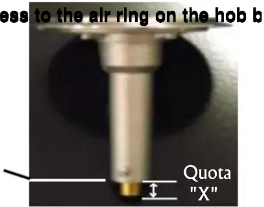
• CORRECORDING BOTTAGEARANOPPEARANCE OF THE FLAME
- Regulating the air ring on the hob buRegulating the air rings on the chable page 60), it is important to position it correctly as it permits correct combustion and enables the burners to work at maximum efficiency.
The table mentions the value "X" in mm; it may be necessary to regulate this by plus or minus 1 mm to obtain a perfect flame.
2. To gain access to the air ring on the hob borgelm: access to the air ring on the hob b
. Remove the pan support, the burner cap and head of the relevant burner.
The air ring is located at the base of the burner unit which is fixed by a screw.
If necessary,
. unscrew the screw that holds the air flow adjuster
. Set the correct distance according to the length that the air adjuster protudes (see page 60).
. Secure the screw when the operation is completed.
text_image
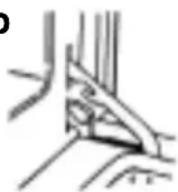
less to the air ring on the hob b Quota "X"3. To gain access to the air ring on the hot plate burner :
. Remove the cast iron hot plate,
. Remove the cast iron hob,
. The air ring is placed on the lengthening of the hot plate burner.
. Unscrew the air ring screw and set according to the table 60.
When re-fitting, ensure that all the elements are properly located.
REGULATING THE MINIMUM FLAME :
1 - Hob burner : remove the control knob,
a) Natural gas : screw the by-pass screw fully home, then unscrew it two turns. Ignite the burner, set the control knob to low position and turn the by-pass screw until you obtain a low, suitable flame.
b) Butane-propane gas : screw the by-pass screw fully home.
2 - Cast-Iron hot plate burner : remove the knob.
a) Natural gas : screw the by-pass fully home then unscrew it two full turns, ignite the burner, set the control knob to minimum position, and adjust the by-pass screw until you obtain a low flame which remains stable when the control knob is turned from maximum to minimum.
Warning : this burner is fitted with a safety device, hold the control knob pushed for a few seconds to allow the safety device to operate.
b) butane-propane gas : the setting is obtained by screwing the by-pass fully home.
INSTALLATION: TIELECTRICAL CONNECTION" "ELECTRICAL
The mains electricity supply connected to the appliance should comply with the norms in force in the country of installation.
ROSIERES declines all responsibility if the above compliance is not observed.
Connection to the mains electricity supply should be through a socket with an earth terminal, or through an intermediary switching device with a gap between contacts of at least 3 mm.
The power supply unit must be protected by appropriate fuses and use cables of a large enough cross section to provide a normal supply to the appliance.
NB : before proceeding with the connection, check the continuity of the earthing of the power supply unit. We cannot be held responsible for any accident or its possible consequences, caused by using an appliance which is not earthed, or whose earthing is defective.
NOTE : Do not forget that the work may need to be carried by the Service Agent. Also, the socket should be located so that the cooker can be connected when it is out of its location.
Power supply cable : if it is necessary to change the power supply cable, it should be done by the Service Agent, or by a similarly qualified person.
The cooker is fitted without a power supply cable. It is fitted with a terminal block which allows you to choose the type of connection suitable for the mains power supply, by operating "shunts" as shown in the table on page 65, after having checked :
. the mains supply tension as shown on the electricity meter,
. the adjustment of the circuit breaker,
. the position of the neutral and earth phases on the socket.
The protection wire of the cable (green/yellow) should be connected to the earth terminals of, at one hand, the appliance and, at the other hand, the mains power supply unit.
CONNECTION TO THE APPLIANCE TERMINALS :
. Remove the back panel by taking out the two screws and slipping it off.
. Pass the cable through the cable grip.
. Strip the insulation off the end of the each wire and connect them to the terminals according to the numbers shown in the table on the next page as well as the "shunts".
. Screw down the cable grip and close the cover.
NOTE : Make sure that the terminal block screws are tight.
SINGLE PHASESINGLE PHASESEPHASESTHREE PHASESEPHASESTHREE PHASE 220-240 V\~220-240 V\~ 220-240 V\~220-240 V\~ 380-415 V\~380-415 V\~
2 phases or 3 phases + neutral
1 phase + neutral
Fuse 25 A Fuse 20 A Fuse 16 A
The guarantee contract consists simply and solely in exchanging or replacing any part considered by us to be defective, or repairing it after examination by our Technical Assistance, to the exclusion of all other indemnities of wathever kind.
DURATION - DURATION is guaranteed for one year from the date of delivery to the first purchaser.
CONDITIONS - CONDITIONS should only be used for the purposes for which it has been designed and as described in this booklet. You should always contact your installer who is responsible for After sales service and who sold you the appliance. The costs of removal, transport and packing for work done under the guarantee will be charged either to the user or to the installer, as stated in the conditions of sale.
AFTER THE GUARANTEE - AFTER THE GUARANTEE who sold you the appliance. They will immediately place on order with our Parts Department for the required components.
LEGAL GUARANTEE - LEGAL GUARANTEE - guarantee do not affect your statutory rights.
When making a claim, or when ordering a part, tell your retailer :
- the exact type of your appliance,
- the serial number (shown on the specification plate) and,
- the name of the part.
To be certain of getting the correct specification, guaranteed for maximum reliability and safety, ask specifically for "CERTIFIED MANUFACTURERS' PARTS".