GLD4400NWW - Washing machine GE - Free user manual and instructions
Find the device manual for free GLD4400NWW GE in PDF.

User questions about GLD4400NWW GE
0 question about this device. Answer the ones you know or ask your own.
Ask a new question about this device
Download the instructions for your Washing machine in PDF format for free! Find your manual GLD4400NWW - GE and take your electronic device back in hand. On this page are published all the documents necessary for the use of your device. GLD4400NWW by GE.
USER MANUAL GLD4400NWW GE
Installation Instructions
Built-In Dishwasher
If you have questions, call 800.GE.CARES (800.432.237) or visit our website a: www.ge.com

BEFORE YOU BEGIN
Read these instructions completely and carefully
IMPORTANT – Observe all governing codes and ordinances.
- Vote to Installer – Be sure to leave these instructions for the consumer's and local inspector's use.
- Vote to Consumer – Keep these instructions with your Owner's Manual for future reference.
- Skill Level – Installation of this dishwasher requires basic mechanical, electrical and plumbing skills. Proper installation is the responsibility of the installer. Product failure due to improper installation is not covered under the GE Appliance Warranty. See warranty information.
- Completion Time – 1 to 3 Hours. New installations require more time than replacement installations.
IMPORTANT – The dishwasher MUST be installed to allow for future removal from the enclosure if service is required.
† you received a damaged dishwasher, you should immediately contact your dealer or builder
Optional Accessories – See the Owner's Manual for available custom panel kits.
FOR YOUR SAFETY
Read and observe all CAUTIONS and WARNINGS shown throughout these instructions. While performing installations described in this booklet, gloves, safety glasses or goggles should be worn.
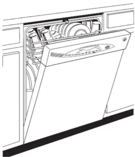
natural_image
Line drawing of a washing machine with multiple compartments and front panel (no text or symbols)READ CAREFULLY.
KEEP THESE INSTRUCTIONS.
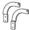
PARTS SUPPLIED
IN INSTALLATION PACKAGE
☐ Two #8-18 x 5/8" Phillips special head screws, to secure dishwasher to underside of countertop.
□ Junction box cover and #10 hex head screw
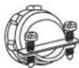
Hose Clamp
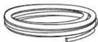
☐ Drain hose (approximately 78" long)
Drain hose hanger
☐ Side and top trim pieces (some models)
□ Literature, samples and/or coupons
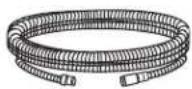
Drain Hose
Side and Top Trim Pieces on some models

natural_image
Pure line drawing of five parallel cylindrical rods (no text or symbols)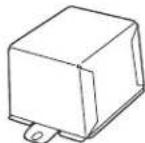
Junction
Box Cover
Screw Kit
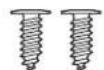
8 Phillips
Special
lead Screws
5/8" long

10
Hex-Head
J-Box Screw
1/2" long
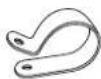
Drain Hose Hanger

Hose Clamp
MATERIALS YOU WILL NEED:
☐ =errule, compression nut and 90° Elbow (3/8"NPT external thread on one end, opposite end sized to fit water supply)
□ Thread seal tape
□ JL Listed wire nuts (3)
☐ GPF65 side mount kit if countertop is granite or similar material
Materials Needed for New Installations:
☐ Air gap for drain hose, if requirec
□ Waste tee for house plumbing, if applicable
□ Electrical cable or power cord
□ Screw type hose clamp
□ Strain relief for electrical connection
□ -land shut-off valve (recommended)
☐ Water line-3/8" minimum copper tubing
☐ GPF10L drain hose (10' long), if needed

90° Elbow
Ferrule and
Compression Nut

Hand
Shut-Off
Valve

Thread
Seal Tape
Wire Nuts (3)

Waste Tee

Electrical Cable
(or Power Cord, it applicable)
Hot Water Line

Air Gap

GPF65
Side-Mount
Bracket Kit

Hose Clamp
Strain Relief

Optional
10' Drain Hose
GPF10L
TOOLS YOU WILL NEED:
☐ Phillips head screwdriver
☐ 1/4" and 5/16" nutdriver
☐ 6" Adjustable wrench
Level
L Carpenters square
□ Measuring tape
☐ Safety glasses
L Flashlight
Gloves
☐ Bucket to catch water when flushing the line
☐ 15/16" socket (optional for skid removal)
For New Installations Only:
L Tubing cutter
L Drill and appropriate bits
☐ Hole saw set
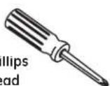
Phillips
Head
Screwdriver
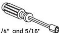
Nutdriver

15/16" Socket

6" Adjustable Wrench
Leve

Carpenters
Square
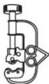
Tubing Cutter

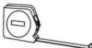
Measuring Tape
Flashlight

Gloves
Bucket

Safety Glasses
Hole Saw Set

PREPARE DISHWASHER ENCLOSUR
text_image
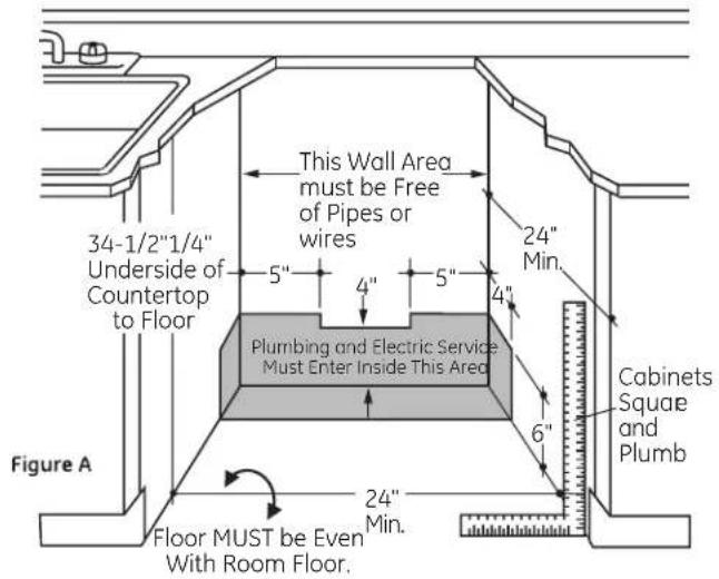
34-1/2"1/4" Underside of Countertop to Floor Figure A Floor MUST be Even With Room Floor. This Wall Area must be Free of Pipes or wires 5" 4" 5" 4" Plumbing and Electric Service Must Enter Inside This Area 24" Min. 6" Cabinets Square and Plumb 24" Min.- The rough cabinet opening must be at least 24" deep, 24" wide and approximately 34-1/2" high from floor to underside of the countertop.
To reduce the risk of electric shock, fire, or injury to persons, the installer must ensure that the dishwasher is completely enclosed at the time of installation.
- The dishwasher must be installed so that drain hose is no more than 10' in length for proper drainage.
- The dishwasher must be fully enclosed on the top, sides and back, and must not support any part of the enclosure.
CLEARANCES: When installed into a corner, allow 2" min. clearance between dishwasher and adjacent cabinet, wall or other appliances. Allow 28-3/8" min. clearance from the front of the dishwasher for door opening. Figure B
Figure B
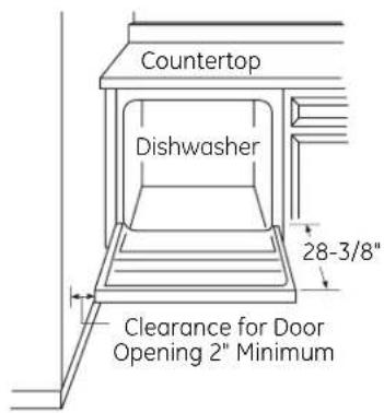
text_image
Countertop Dishwasher 28-3/8" Clearance for Door Opening 2" MinimumDRAIN REQUIREMENTS
- Follow local codes and ordinances.
- Do not exceed 10' distance to drain.
NOTE: Air gap must be used, if waste tee or disposer connection is less than 18" above floor to prevent siphoning.
DETERMINE DRAIN METHOD
The type of drain installation depends on the following questions.
☐ Do local codes or ordinances require an air gap? ☐ Is waste tee less than 18" above floor?
If the answer to either question is YES, Method 1 MUST be used.
- If the answers are NO, either method may be used.
CABINET PREPARATION
- Drill a 1-1/2" diameter hole in the cabinet wall within the shaded areas shown in Figure A for the drain hose connection. The hole should be smooth with no sharp edges.
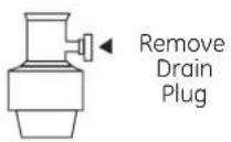
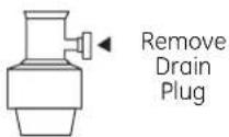
IMPORTANT - When
connecting drain line to disposer, check to be sure that drain plug has been removed. DISHWASHER WILL NOT DRAIN IF PLUG IS LEFT IN PLACE
natural_image
Technical line drawing of a shared plumbing system inside a shared room (no text or labels)
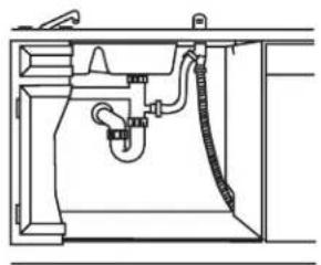
natural_image
Technical line drawing of a mechanical or plumbing assembly (no text or symbols)Figure C
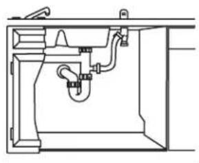
Method 1 - Air Gap with Waste Tee or Dispose
An air gap must be used when required by local codes and ordinances. The air gap must be installed according to manufacturer's instructions.

text_image
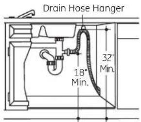
Drain Hose Hanger 32" Min. 18" Min.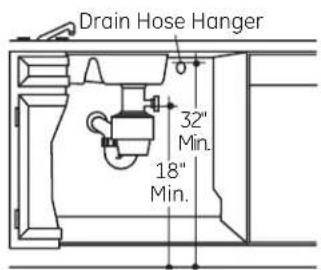
text_image
Drain Hose Hanger 32" Min. 18" Min.Figure D
Method 2 - "High Drain Loop" with Waste Tee or Disposer
Tip: Avoid unnecessary service call charges
Always be sure disposer drain plug has been removed before attaching dishwasher drain hose to the disposer.
PREPARE ELECTRICAL WIRING
FOR PERSONAL SAFETY: Remove house fuse or open circuit breaker before beginning installation. Do not use an extension cord or adapter plug with this appliance.
Electrical Requirements
- This appliance must be supplied with 120V, 60 Hz., and connected to an individual properly grounded branch circuit, protected by a 15 or 20 ampere circuit breaker or time delay fuse.
- Wiring must be 2 wire with ground and rated for 75^ (176°F). - If the electrical supply does not meet the above requirements call a licensed electrician before proceeding
Grounding Instructions-Permanent Connection
This appliance must be connected to a grounded metal, permanent wiring system, or an equipment grounding conductor must be run with the circuit conductors and be connected to the equipment grounding terminal or lead on the appliance.
Grounding Instructions-Power Cord Models
This appliance must be grounded. In the event of a malfunction or breakdown, grounding will reduce the risk of electric shock by providing a path of least resistance for electric current. This appliance is equipped with a cord having an equipment grounding conductor and a grounding plug. The plug must be plugged into an appropriate outlet that is installed and grounded in accordance with all local codes and ordinances.
The improper connection of the equipment grounding conductor can result in a risk of electric shock. Check with a qualified electrician or service representative if you are in doubt that the appliance is properly grounded.
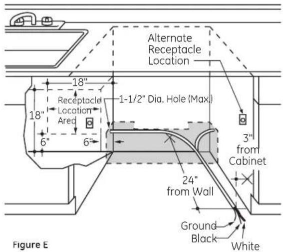
text_image
Alternate Receptacle Location 18" Receptacle Location Ared 1-1/2" Dia. Hole (Max) 6" 6" 3" from Cabinet 24" from Wall Ground Black White Figure EFor models equipped with power cord: Do not modify the plug provided with the appliance; if it will not fit the outlet, have a proper outlet installed by a qualified technician
Cabinet Preparation & Wire Routing
- The wiring may enter the opening from either side, rear or the floor within the shaded area illustrated above in Figure E and defined in Figure A. - Cut a 1-1/2" maximum diameter hole to admit the electrical cable. Permanent wiring connections may pass through the same hole as the drain hose and hot water line, if convenient. If cabinet wall is metal, the hole edge must be covered with c bushing.
NOTE Power cords with plug must pass through a separate hole.
Electrical Connection to Dishwasher
Electrical connection is on the right front of dishwasher
- For permanent connections the cable must be routed as shown in Figure E. Cable must extend a minimum of 24" from the rear wall.
- For power cord connections, install a 3-prong grounding type receptacle in the sink cabinet rear wall, 6" min. or 18" maximum from the opening, 6" to 18" above the floor
PREPARE HOT WATER LINE
- The line may enter from either side, rear or floor within the shaded area shown in Figure F.
- The line may pass through the same hole as the electrical cable and drain hose. Or, cut an additional 1-1/2" diameter hole to accommodate the water line. If power cord with plug is used, water line must not pass through power cord hole.
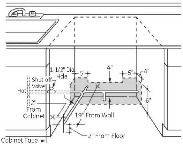
text_image
1-1/2" Dia Hole 5" 4" 5" 4" 6" Shut-off Valve Hot 2" From Cabinet 19" From Wall 2" From Floor Cabinet Face→Figure F
Water Line Connection
- Turn off the water supply.
- Install a hand shut-off valve in an accessible location, such as under the sink. (Optional, but strongly recommended and may be required by local codes.)
- Water connection is on the left side of the dishwasher. Install the hot water inlet line, using no less than 3/8" copper tubing. Route the line as shown in Figure F and extend forward at least 19" from rear wall.
- Adjust water heater for 120^ to 150^ temperature.
- Flush water line to clean out debris.
• The hot water supply line pressure must be 20-120 PSI.
Turn page to begin dishwasher installation.

UTION
Do not remove wood base until you are ready to install the dishwasher. The dishwasher will tip over when the door is opened if base is removed.
STEP 1: PREPARATION
Locate the items in the installation package and set aside for use in the listed steps:
- Screw kit – Steps 5 or 18 and 15
- Junction box cover - Step 5 or 18
- Drain hose and clamp – Step 7
- Drain hose hanger - Step 17
- Trim pieces (some models) - Step 11
- Owner's Manual - Steps 19 and 22
• Product Samples and/or coupons – Step 22
STEP 2: CHECK DOOR BALANCE
- With dishwasher on the wood base, check the door balance by opening and closing the door.
- Door is properly balanced if it gently drops from a 1/2 open position and does not rise from the full open position.
- If necessary increase or decrease tension as shown. Latch door and adjust both springs to the same tension setting to correct balance.
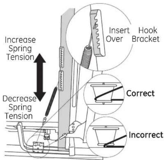
text_image
Increase Spring Tension Decrease Spring Tension Insert Hook Bracket Correct IncorrectFigure G
Tip: Make sure door opens and closes smoothly
Check door opening and closing. If door does not open easily or falls too quickly, check spring cable routing. The cable is held in place by "shoulders" on the pulley. Check to be sure cable has not slipped over the pulley shoulders.
STEP 3: REMOVE WOOD BASE INSTALL LEVELING LEGS
IMPORTANT – Do not kick off wood base! Damage will occur.
- Move the dishwasher close to the installation location and lay it on its back.
- Remove the four leveling legs on the underside of the wood base with a 15/16" socket wrench.
- Discard base.
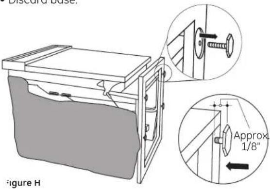
text_image
Discard base. Figure H Approx. 1/8"- Screw leveling legs back into the dishwasher frame, approximately 1/8" from frame as shown.
STEP 4: REMOVE TOEKICK
- Remove the 2 toekick screws and toekick. Set aside for use in Step 21.

text_image
Toekick Remove 2 Toekick ScrewsFigure I
STEP 5: INSTALL POWER CORD
Skip this step if dishwasher will be permanently connected to the house electrical system.
In this step you will need the junction box cover and the #10 x 1/2" hex head screw from the screw kit set aside in Step 1.
The power cord and connections must comply with the National Electrical Code, Section 422 and/or local codes and ordinances. Maximum power cord length is 6 feet. Power Cord Kit WX09X70910, available for purchase from an authorized GE Appliance Dealer, meets these requirements.
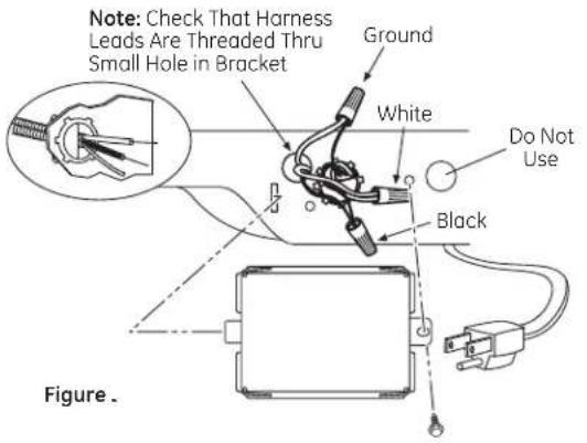
text_image
Note: Check That Harness Leads Are Threaded Thru Small Hole in Bracket Ground White Do Not Use Black Figure.• Install strain relief in junction box bracket.
- Insert power cord through strain relief and tighten.
- Make sure black, white and green dishwasher wires are threaded through small hole in junction box bracket.
- Connect power cord white (or ribbed) to dishwasher white wire, black (or smooth) to dishwasher black wire and ground to dishwasher green wire. Use UL listed wire nuts of appropriate size.
• Install junction box cover using #10 Hex head screw. Be sure wires are not pinched under the cover
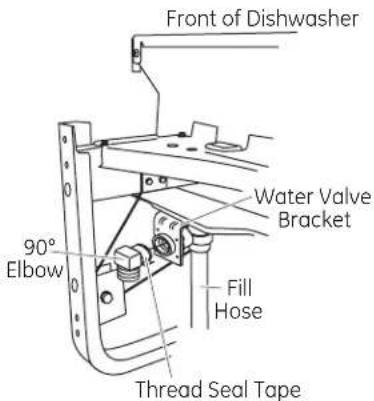
STEP 6: INSTALL 90° ELBOW
- Wrap a 90^ elbow with thread seal tape.
- Thread 90^ elbow onto the water valve
- Do not over tighten elbow. Water valve bracket could bend or water valve fitting could break.
- Position the end of the elbow to face the rear of the dishwasher
text_image
Front of Dishwasher 90° Elbow Water Valve Bracket Fill Hose Thread Seal TapeFigure K
STEP 7: INSTALL DRAIN HOSE TC PUMP OUTLET
Skip this step if drain hose has been pre-installed.
n this step you will need the drain hose and clamp set aside in Step 1
- Stand dishwasher upright.
- Place drain hose clamp over 1-3/16" diameter end of drain nose. Position clamp so screw is on bottom side of hose. Refer to Figure L.
IMPORTANT - Prevent drain hose damage and possible leaks. Be careful not to nick or cut the drain hose.
- Push the end of the drain hose over the drain pump outlet being careful not to disturb the check valve. Refer to Figure L.
- Seat the drain hose end against the hose stops on the pump outlet.
- Position hose clamp against the front lip of the drain hose and tighten clamp.
Vote: Drain hose supplied with dish washer is approximately 78" long. If a longer hose is needed, a 120" long hose (10 feet) may be purchased from an authorized GE appliance dealer.
The 10' long hose
s part number GPF10L
Pump Outlet
Hose Stops

text_image
s part number GPF10L Hose stops Hose Clamp Check Valve Do Not Remove Figure LTip: Avoid unnecessary service charges. Make a leak free connection
Insert hose against stop on pump. Position clamp against front lip of drain hose with clamp screw on bottom side of hose.
Tighten clamp to at least 15 inch-pounds of torque.
Tip: Reduce drain pump noise
Position drain hose clamp so screw is on the bottom side of the hose. This will prevent noise caused by the clamp coming in contact with the tub bottom. Refer to Figure L.
STEP 8: POSITION WATER LINI AND HOUSE WIRING
- Position water supply line and house wiring on the floor of the opening to avoid interference with base of dishwasher and components under dishwasher.

text_image
4" 5" 5" 4" 6" 4" 6" Water Line House WiringFigure M
STEP 9: INSTALL DRAIN HOSE, THROUGH CABINET
- Position dishwasher in front of cabinet opening. Insert drain hose into the hole in cabinet side. If a power cord is used, guide the end through a separate hole

text_image
Insulation Blanket Water Line Maximum Drain Hose Length 10" Drain Hose House Wiring Power Cord (If Used) Figure NTip: Prevent unnecessary service call charges for no fill, drain or noise concerns
Position utility lines so they do not interfere with anything under or behind the dishwasher.
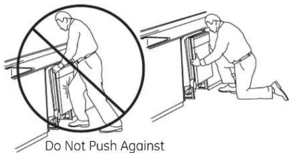
STEP 10: SLIDE DISHWASHEF THREE-FOURTHS OF THE WAY INTO CABINET
IMPORTANT – Do not push against front panel with knees. Damage will occur.
- Grasp the sides of the front panel and slide dishwasher into the opening a few inches at a time.
text_image
Do Not Push AgainstDo Not Push Against
Front Door Panel With
Knee. Damage to The
Door Panel Will Occur.
- As you proceed, pull the drain hose through the opening under the sink. Stop pushing when the dishwasher extends about 6 inches forward of adjacent cabinets.
- Make sure drain hose is not kinked under or behind the dishwasher.
- Make certain the house wiring, drain line and water line do not interfere with components under dishwasher
STEP 11: INSTALL TRIM PIECES (some models)
Skip this step if trim is not supplied with the dishwasher. In this step you will need the trim pieces set aside in Step 1.
- Position the trim pieces so the lips face toward the dishwasher door.
- Select a long trim piece and press it onto the left side tub fl ange. Start with the top edge and press the trim piece completely onto the tub fl ange as you move towards the bottom. Repeat for the right side tub fl ange trim piece
• Install remaining trim piece on the top tub fl ange

text_image
Trim Strip Trim Strip Trim Strip Top View Figure PSTEP 12: INSTALL GPF65 SIDE-MOUNT BRACKETS
Skip this step if underside of countertop is wood or wood-like material.
• Install side-mount brackets if underside of countertop is granite or similar material that will not accept wood screws.
Note: The brackets are available for purchase it needed. Obtain a GPF65 kit from your authorized GE Appliance Dealer.
- Fasten the left-hand bracket to the left side of the dishwasher frame and the right-hand bracket to the right side of the dishwasher frame, using the #8 pan-head screws included with the kit. Refer to instructions included in kit for orientation and placement of the brackets.
Optional Side-Mount Bracket Kit

text_image
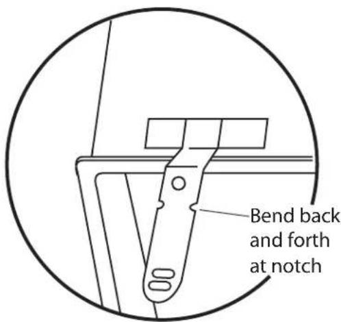
Side-Mounting Brackets Tub Frame Countertop Brackets Bracket Attachment Screws (2 Each Side)- If you are installing the dishwasher under a counter with a short overhang, the countertop brackets may extend beyond the edge of the counter. If this is the case, remove the excess length by repeatedly bending the brackets at the notches until they break off.
text_image
Bend back and forth at notchSTEP 13: PUSH DISHWASHER INTO FINAL POSITION
- Check the tub insulation blanket, if equipped, to be sure it is smoothly wrapped around the tub. It should not be "bunched up" and it must not interfere with the door springs. If the insulation is "bunched up" or interfering with the springs, straighten and re-center the blanket prior to sliding the dishwasher into its final position.
- Slide the dishwasher into the final position by pushing on the sides of the door panel. Do not use a knee or push on the center of the panel. If you do, damage to the panel will likely result.
- The dishwasher is in the final position when the edges of the front panel are flush with the adjacent cabinets and the dishwasher is centered in the cabinet opening.
IMPORTANT – Before opening the dishwasher door, be certain the edges of the dishwasher door panel are behind the face of the adjacent cabinet and not up against the cabinet face. Refer to Figure Q. If the dishwasher door is opened when the edge of the door is against the face of the cabinet, dishwasher door damage and cabinet damage will occur.
- Open and close the dishwasher door to be sure it operates smoothly, and does not rub on the adjacent cabinet.
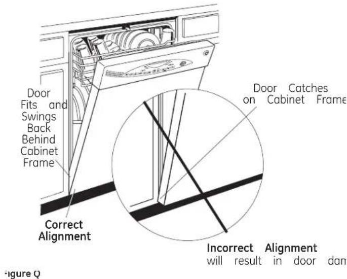
text_image
Door Fits and Swings Back Behind Cabinet Frame Correct Alignment Door Catches on Cabinet Frame Incorrect Alignment will result in door dan Figure QTip: Prevent unnecessary service charges for panel damage or wash performance
Check dishwasher alignment prior to opening dishwasher door to prevent panel damage.
Make sure utility lines are not trapped or crushed behind dishwasher. Crushed lines will restrict water flow.
STEP 14: LEVEL DISHWASHER
IMPORTANT - Dishwasher must be level for proper dish rack operation, wash performance and door operation. The dishwasher must be leveled left to right and front to back. This assures the dish racks will not roll in or out on their own, circulation water will flow to the pump inlet, and the door will close without hitting the side of the tub.
- Remove the lower dish rack and place a level on the door and lower rack track as shown in Figure R.
- Adjust the level of the dishwasher by individually turning the four legs on the bottom of the dishwasher as illustrated in Figure S.
- The dishwasher is properly leveled when the level indicator is centered left to right and front to back. Also, the dishwasher door should close without hitting the side of the tub.
- Replace the lower rack.

text_image
Check Level Front- to-Back Lower Rack Tracks Check Level Side- to-SideFigure R

text_image
Turn Legs to AdjustFigure S
Tip: Prevent unnecessary service charges. Verify dishwasher is leveled
Pull the dish racks half way out. They should stay put. Open and close the door. The door should fit in the tub opening without hitting the side of the tub. If the racks roll on their own, or the door hits the side of tub, re-level the dishwasher
STEP 15: POSITION DISHWASHER, SECURE TO COUNTERTOP OR CABINET
n this step you will need the 2 Phillips special head screws from the screw kit set aside in Step 1.
The dishwasher must be secured to the countertop or the cabinet sides. When the underside of the countertop is wood, use Method 1 Use Method 2 when the underside of the countertop is made of a material, such as granite, that will not accept wood screws
IMPORTANT – Prevent door panel and control panel damage. Dishwasher must be positioned so the front pane and control panel do not contact the adjacent cabinets or countertop. Mounting screws must be driven straight and flush. Protruding screw heads could scratch the door panel or control panel and interfere with door operation.
Method 1
Secure dishwasher to underside of wood countertop.
- Recheck alignment of the dishwasher in the cabinet. Refer to Steps 13 and 14. Door panel and/or control panel must not hit cabinets or countertop.
- Fasten the dishwasher to the underside of the countertop with the 2 Phillips special head screws. Refer to Figure T. Make certain screws are driven straight and flush to prevent pane damage.

text_image
Brackets Wood CountertopFigure T
Method 2
Secure dishwasher to cabinet sides. This method requires purchase of a GPF65 Side Mount Kit. Refer to Step 12.
- Recheck alignment of the dishwasher in the cabinet. Refer to Steps 13 and 14. Door panel and/or control panel must not hit cabinets or countertop.
- Fasten the dishwasher to the adjacent cabinets with the 2 Phillips special head screws provided. Refer to Figure U. Make certain screws are driven straight and flush to prevent pane damage.

text_image
Granite Countertop Side BracketsFigure U
STEP 16: CONNECT WATER SUPPLY
Connect water supply line to 90° elbow
- Slide compression nut, then ferrule over end of water line.
- Insert water line into 90^ elbow.
- Slide terrule against elbow and secure with compression nut.
IMPORTANT - Check to be sure that door spring and/or door spring cable do not rub or contact the fill hose or
water supply line.
Test by opening and closing the door. Re-route the water supply lines if a 'ubbing noise or nterference occurs
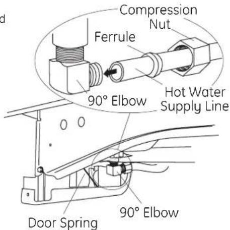
text_image
Compression Nut Ferrule 90° Elbow Hot Water Supply Line Door Spring 90° ElbowFigure V
STEP 17: CONNECT DRAIN LINE
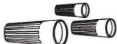
The molded end of the drain hose will fit 5/8" through 1" diameter inlet ports on the air gap, waste tee or disposer
- Determine size of inlet port
- Cut drain hose connector on the marked line, if required, to fit the inlet port.

text_image
Cutting Line 1" 5/8"Figure W
IMPORTANT: Do not cut corrugated portion of hose
- If a longer drain hose is required and you did not purchase drain hose GPF10L, add up to 42" length for a total of 120" (10 feet) to the factory installed hose. Use 5/8" or 7/8" inside diameter hose and a coupler to connect
the two hose ends.
Secure the connection with hose clamps
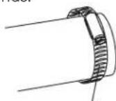
Figure X

Coupler
Hose Clamp
Vote: TOTAL DRAIN HOSE LENGTH MUST NOT EXCEED 10 FEET FOR PROPER DRAIN OPERATION.
- Connect drain line to air gap, waste tee or disposer using the previously determined method. Secure hose with a screw type clamp.
Method 1 – Air gap with waste tee or disposer
natural_image
Technical line drawing of a mechanical assembly with pipes and housing (no text or symbols)Waste Tee Installation

natural_image
Technical line drawing of a mechanical assembly inside a container (no text or symbols)Disposer Installation
Figure Y
Method 2 - "High drain loop" with waste tee or disposer With this method you will need the drain hose hanger set aside in Step 1
Fasten drain hose to uncerside of countertop with the provided hanger
text_image
Drain Hose Hanger 18" Min. 32" Min.Waste Tee Installation

text_image
18" Min. 32" Min.Disposer Installation
Figure 2
IMPORTANT - When connecting drain line to disposer, check to be sure that drain plug has been removed DISHWASHER WILL NOT DRAIN IF PLUG IS LEFT IN PLACE.
Tip: Avoid unnecessary service call charges for a no drain complaint
Make sure excess drain hose has been pulled through the cabinet opening. This will prevent excess hose in the dishwasher cavity from becoming kinked or crushed by the dishwasher.
STEP 18: CONNECT POWER SUPPLY
If a power cord with plug is already installed proceed to Step 19.

If house wiring is not 2-wire with ground, a ground must be provided by the installer. When house wiring is aluminum, be sure to use UL Listed anti-oxidant compound and aluminum-to-copper connectors
n this step you will need the junction box cover and the #10 Hex head screw from the screw kit set aside in Step 1
- Secure house wiring to the back of the junction box with a strain relief.
- Locate the three dishwasher wires, (white, black and green) with stripped ends. Insert dishwasher wires through the small hole in the junction box bracket. Use UL listed wire nuts of appropriate size to connect incoming ground to green, white to white and black to black.
- Install the junction box cover using #10 hex head screw. Check to be sure that wires are not pinched under the cover

text_image
Note: Check That Harness Leads Are Threaded Thru Small Hole in Bracket Ground White Do Not Use Black Figure AASTEP 19: PRETEST CHECK LIST
Review this list after installing your dishwasher to avoid charges for a service call that is not covered by your warranty.
☐ Check to be sure power is OFF.
☐ Open door and remove all foam and paper packaging.
□ Locate the Owner's Manual set aside in Step 1.
Read the Owner's Manual for operating instructions.
☐ Check door opening and closing. If door does not open and close freely, check for proper routing of spring cable over pulley. If door drops or closes when released, adjust spring tension. See Step 2,
☐ Check to be sure that wiring is secure under the dishwasher not pinched or in contact with door springs or other components. See Step 10.
☐ Check door alignment with tub. If door hits tub, level dishwasher. See Steps 14 and 15
☐ Pull lower rack out, about halfway. Check to be sure it does not roll back or forward on the door. If the rack moves, adjust leveling legs. See Step 14.
☐ Check door alignment with cabinet. If door hits cabinet, reposition dishwasher. See Step 15.
☐ Check that door spring does not contact water line, fill hose, wiring or other components. See Step 16.
☐ Verify water supply and drain lines are not kinked or in contact with other components. Contact with motor or dishwasher frame could cause noise.
☐ Turn on the sink hot water faucet and verify water temperature. Incoming water temperature must be between 120°F and 150°F. A minimum of 120°F temperature is required for best wash performance. See "Prepare Hot Water Line," page 5.
☐ Add 2 quarts of water to the bottom of the dishwasher to lubricate the pump seal.
☐ Turn on water supply. Check for leaks. Tighten connections it needed.
☐ Remove protective film if present from the control panel and door.
STEP 20: DISHWASHER WET TEST
☐ Turn on power supply or plug power cord into outlet, it equipped.
□ Latch door.
☐ Push "Rinse Only" pad.
☐ Push Start/Reset pad one time. Dishwasher should start.
☐ Check to be sure that water enters the dishwasher. If water does not enter the dishwasher, check to be sure that water and power are turned on.
☐ Check for leaks under the dishwasher. If a leak is found, turn off power at the breaker, and then tighten water connections. Restore power after leak is corrected
☐ Check for leaks around the door. A leak around the door could be caused by door rubbing or hitting against adjacent cabinets. Reposition the dishwasher if necessary. See Step 15
☐ The dishwasher will drain and turn off about 5 minutes after it was started. Check drain lines. It leaks are found, turn off power at the breaker and correct plumbing as necessary. Restore power after corrections are made. See Steps 7 and 17.
Open dishwasher door and make sure most of the water has drained. It not, check that disposer plug has been removed and/or air gap is not plugged. Also check drain hose to be sure it is not kinked underneath or behind dishwasher. See Step 17
☐ Press Start/Reset pad once again and run dishwasher through another "Rinse Only" cycle. Check for leaks and correct if required.
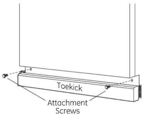
STEP 21: REPLACE TOEKICK
- Place toekick against the legs of the dishwasher
text_image
Toekick Attachment ScrewsFigure CC
- Align the toekick with the bottom edge and make sure it is against the floor
- Insert and tighten the two toekick attachment screws. The toekick should stay in contact with the floor
Tip: Reduce sound from under the dishwasher Make sure toekick is against floor
STEP 22: LITERATURE
- Be sure to leave complete literature package, these installation Instructions and product samples and/or coupons with the consumer
SPECIFICATIONS SUBJECT TO CHANGE WITHOUT NOTICE

GE Consumer & Industrial
General Electric Company
Louisville, Kentucky 40225
ge.com
© 2005 General Electric Company
Pub. No. 31-30217
Dwg. Nc. 206C1559P157
ND 06G-1871 (8/0€)