ZCG3500DSS - Compacteur encastrable GE - Free user manual and instructions
Find the device manual for free ZCG3500DSS GE in PDF.

User questions about ZCG3500DSS GE
0 question about this device. Answer the ones you know or ask your own.
Ask a new question about this device
Download the instructions for your Compacteur encastrable in PDF format for free! Find your manual ZCG3500DSS - GE and take your electronic device back in hand. On this page are published all the documents necessary for the use of your device. ZCG3500DSS by GE.
USER MANUAL ZCG3500DSS GE
Installation Instructions
If you have questions, call 800.626.2000 or visit our website at: www.monogram.com
Built-In Compactors
Models:
ZCG3500
ZCG3300
ZCG3100
Before you begin—Read these instructions completely and carefully.
IMPORTANT: Save these instructions for local inspector's use.
IMPORTANT: OBSERVE ALL GOVERNING CODES AND ORDINANCES.
NOTE TO INSTALLER: Be sure to leave these instructions with the Consumer.
NOTE TO CONSUMER: Keep these instructions with your Use and Care Book for future reference.
WARNING This appliance must be properly grounded. See “Power Supply”, page 5.
AVERTISSEMENT
If you have a question concerning the installation of this product, call the GE Answer Center® Consumer Information Service at 800.626.2000, 24 hours a day, 7 days a week.
If you received a damaged compactor, you should immediately contact your dealer or builder.
Proper installation is the responsibility of the installer. Product failure due to improper installation is not covered under the GE Appliance Warranty. See the Owner's Manual for warranty information.
For Monogram local service in your area, 800.444.1845 For Monogram Parts and Accessories, call 800.626.2002.
CAUTION
NOTICE
- Compactor is shipped with ram in "Down" position. Trash container compartment cannot be opened until the ram is restored to normal "UP" position. See label on compactor.
- Compactor has adjustable base to set toekick depth to match cabinets. This adjustment must be made prior to installing unit under countertop. See page 8.
- Compactor is designed for BUILT-IN applications ONLY.
- Consideration must be given to provide adequate clearances for installation and servicing.
- Do not use an extension cord or adaptor plug with this appliance.
MISE EN GARDE
AVIS
Models Available 3
Dimensions and Clearances ....3
Installation Preparation
Standard Appearance Panel Option ....4
Custom Panels 4
Option 1: 1/4" Thick Wood Panel ....4
Option 2: 3/4" Thick Wood Panel ....4
Option 3: 3/4" Thick Wood panel with Custom Handle....5
Power Supply 5
Installation
Technical Data 6
Choosing the Location 6
Installation in a Corner 7
Level the Opening 7
Step 1 Determine Toekick Depth ....8
Step 2 Adjust Movable Base 8
Step 3 Positioning the Compactor Backstop ....9
Step 4 Setting the Height 9
Step 5 Attach Tip-Over Brackets ....10
Step 6 Optional Custom Toekick ....11
Step 7 Changing Front Panel ....12
Optional Custom Panels 13
Models available
ZCG3500 SS
Stainless steel built-in compactor
ZCG3300 WW
White built-in compactor
ZCG3100 BB
Black built-in compactor
Note: This compactor is designed for built-in applications only.
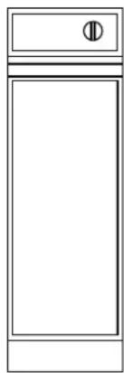
natural_image
Simple line drawing of a rectangular cabinet or enclosure with a small circular symbol on the top (no text or labels)An extra touch of convenience for the custom kitchen, the Monogram built-in compactor is a neat 12" wide.
This compactor offers design flexibility not found in other models—an adjustable base allows the toekick depth to match surrounding cabinetry.
Dimensions and clearances
A - 34" (864 mm) adjustable to 35" (889 mm)
B - 12" (305 mm)
C-20-1/4" (514 mm)
D - 22" (559 mm)
E-2-3/4" to 4-1/4"
(70 mm to 108 mm)
base is adjustable from
front panel
Note: If cord is to be plugged in directly behind compactor add 2-1/2" to overall depth in order to allow proper clearance for the electrical cord.

text_image
Door (Hinged Open) Trash Drawer 1" See Note A 3 to 4 ft. Usable Length D C B EInstallation Preparation
| Built-In Compactors | ||
| Standard Appearance Panel Options | The Monogram compactor models ZCG3300 and ZCG3100 come with a white/black reversible aluminum front drawer panel. Model ZCG3300 is shipped with the white panel showing and model ZCG3100 with the black side showing. The panels on both models can be reversed to reveal the opposite color side. The ZCG3500 comes with a stainless steel wrapped panel.Go to Step 7, page 12. Follow procedure A for reversing door panel color if desired. | |
| Custom Panels | Monogram compactor models ZCG3300 and ZCG3100 are designed to accept a custom front drawer panel to match the surrounding cabinetry. | You can:• Install a 1/4" thick custom panel• 3/4" thick custom panel• 3/4" thick custom panel and custom handle |
| Option #1 | 1/4" Thick Wood Panel• Cut panel 11-11/16" wide, 24-1/2" high.The custom 1/4" thick panel replaces the white/black aluminum panels and cardboard filler.The custom panel will slide into the trim on the drawer front, concealing raw cut edges.Go to Step 7, page 12. Follow procedure B for installation. | 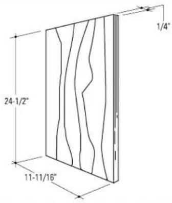 |
| Option #2 | 3/4" Thick Wood Panel• Cut panel 12" wide x 24-3/4" high.The custom 3/4" thick panel replaces the white/black aluminum panel. Cut edges will be seen and must be finished for best appearance. Both the trim and drawer front panel will be removed to make this installation.Go to Step 7, page 12. Follow procedure C for installation.Note: 3/4" thick door panels, both raised and flat design, should be constructed in the same manner as typical cabinet doors. Order the 3/4" custom door panel from the cabinet manufacturer. Be sure to provide the exact dimensions so that the panel is constructed accurately. |  |
Option #3
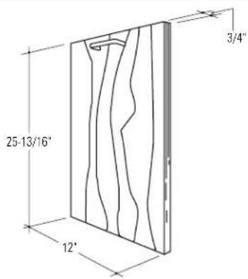
3/4" Thick Wood Panel with custom handle
- Cut panel 12" wide x 25-13/16" high. A custom handle, of your choice, can be installed onto the 3/4" wood panel, replacing the standard handle. The cut edges of the custom panel can be seen and must be finished for best appearance. The trim, drawer front panel and the handle will be removed to make this installation.
Go to Step 7, page 14. Follow procedure D for installation.
Note: 3/4" thick door panels, both raised and flat design, should be constructed in the same manner as typical cabinet doors. Order the 3/4" custom door panel from the cabinet manufacturer. Be sure to provide the exact dimensions so that the panel is constructed accurately. Order custom handle to match cabinetry hardware.
text_image
25-13/16" 12" 3/4"Power supply
CAUTION
For personal safety, do not use an extension cord or adapter plug with this appliance.
Do not, under any circumstances, cut or remove the third grounding prong from the power cord.
MISE EN GARDE
text_image
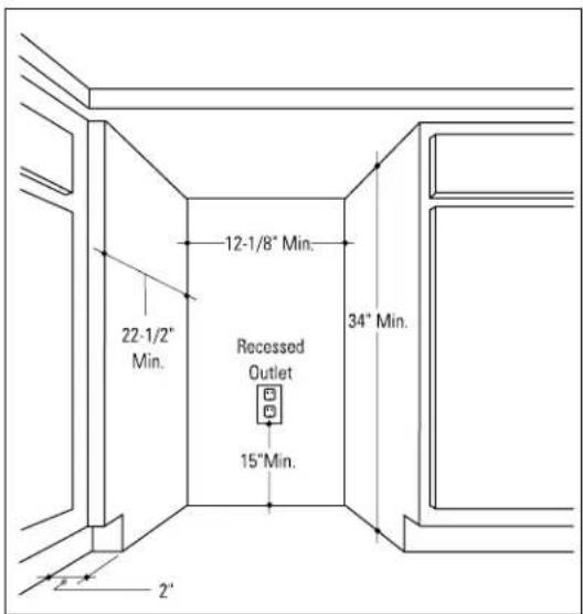
22-1/2" Min. 12-1/8" Min. 34" Min. Recessed Outlet 15" Min.Follow national electrical codes or prevailing local codes and ordinances.
Note: The outlet location is critical for proper cord storage when compactor is installed.
This appliance must be supplied with 120V, 60HZ and connected to an individual, properly grounded branch circuit protected by a 15 or 20 amp circuit breaker or time delay fuse.
Install a 3-prong grounding type receptacle in the rear wall of the cabinet opening.
Note: Usable power cord length is 3 to 4 ft.

text_image
3 to 4 ft. Usable Power CordInstallation
Built-In Compactors
Tools required:
-
2 Phillips head screwdriver
- Flat blade screwdriver
- Tape measure
- Spirit level
- 10° long 2x4
- Adjustable wrench or slip joint pliers
- Drill and 1/8" drill bit
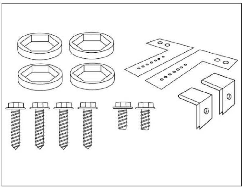
Parts List:
- 4 leveling feet caps
• 4 Phillips head screws
• 2 Slotted head screws - 2 Tip-over brackets
- 2 90° clips
Optional Materials (not supplied):
- Custom front panel
- Custom handle
- Custom toekick board
- 5 wood screws
natural_image
Technical line drawings of various screw and bracket components (no text or labels)Technical data
Electric Power—120V, 60 HZ, 5 amp Circuit Requirement—15 or 20 amp grounded outlet Motor Horsepower—1/3 Compacting Force—5000# max.
Container volume—1.4 cu. ft. Weight—135 lbs. Cycle Time—70 sec. max., 12 sec. min.
Choosing the location
This compactor is designed as a built-in appliance only. It may be located in any convenient space under a countertop. DO NOT OPERATE FREE-STANDING because the compactor will tip over when the drawer is pulled out.

text_image
22-1/2" Min. 12-1/8" Min. Recessed Outlet 34" Min. 15" Min.Installation in a corner
If compactor is to be located in or near a corner of base cabinets, a minimum of 2" clearance from the corner is recommended. This is necessary to prevent adjacent cabinet door handles from interfering with the compactor drawer.
text_image
22-1/2" Min. 12-1/8" Min. Recessed Outlet 34" Min. 15"Min. 2" 2'Level the opening
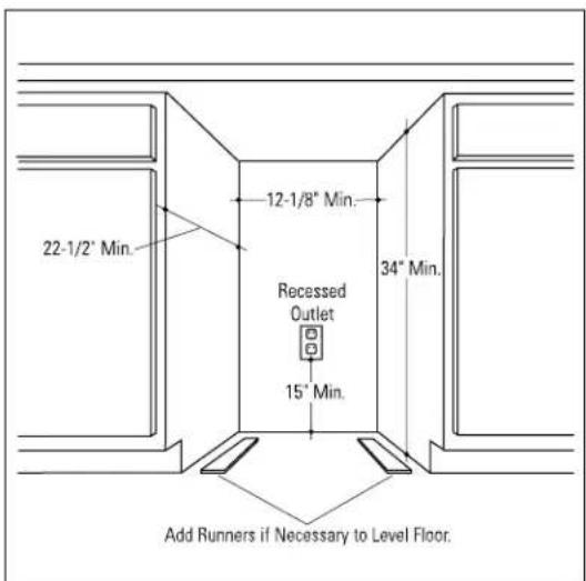
Do not install flooring material after compactor is placed under the counter. This will limit ability to service.
If there is an appreciable difference in floor height between where the compactor is to be installed and the floor of the kitchen, add runners of the minimum height necessary to make floor level.
text_image
22-1/2" Min. 12-1/8" Min. Recessed Outlet 15" Min. 34" Min. Add Runners if Necessary to Level Floor.Installation
Built-In Compactors
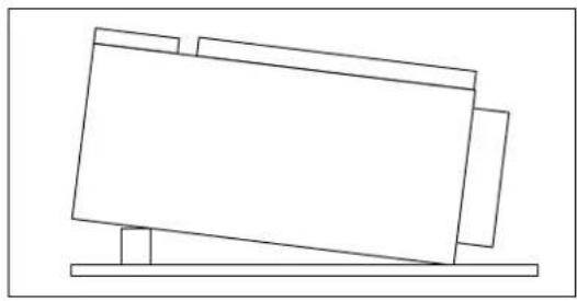
Step 1 Determine toekick depth
Place a section of the carton on the floor for protection. Lay the compactor on its back, supporting it with a piece of wood to prevent pressure on the power cord.
natural_image
Simple line drawing of a tilted rectangular object resting on a horizontal base (no text or symbols)Measure the toekick of an adjacent cabinet, from the front of the cabinet door to the front of the toekick (Dimension A).
Note: If a custom toekick board is used, its thickness must be accounted for in dimension "A". See step 6.

text_image
Cabinet Door Cabinet AStep 2 Adjust movable base
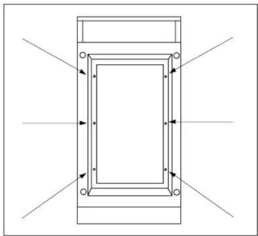
With the compactor laying on its back, locate the six Phillips head screws on the bottom, positioned inside of the movable base.
natural_image
Pure technical diagram of a rectangular frame with directional arrows indicating flow or force, no text or symbols present.Loosen these six screws. Slide base to set dimensions "A" as shown.
Tighten screws making sure base does not move.
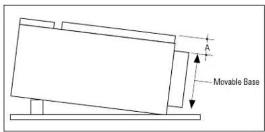
text_image
A Movable BaseNote: If an alternate toekick depth dimension is required, follow the procedure above and adjust the base accordingly. The base can be adjusted from 2-3/4" to 4-1/4" from the compactor front panel.

text_image
Compactor 2-3/4" to 4-1/4"Step 3 Positioning the compactor backstop
A backstop should be installed to prevent the compactor from "walking" back when the drawer is closed.
Measure and mark 16" back from the front edge of the cabinet toekick. Cut a 2x4, 10" long and anchor to the floor.
Note: If using a custom toekick, add that thickness to the 16" measurement.

text_image
Front Edge of Base 16° 10° 2' x 4" Cabinet Back FloorStep 4 Setting the height
Measure height "B" from the underside of the countertop to the floor where the compactor will be setting.
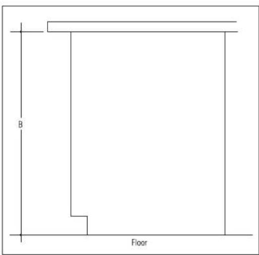
text_image
B FloorWith the compactor still laying on its back, adjust leveling feet to 1/16" less than the measurement of "B". Place the plastic leveling feet caps over the leveling feet and stand compactor upright.

natural_image
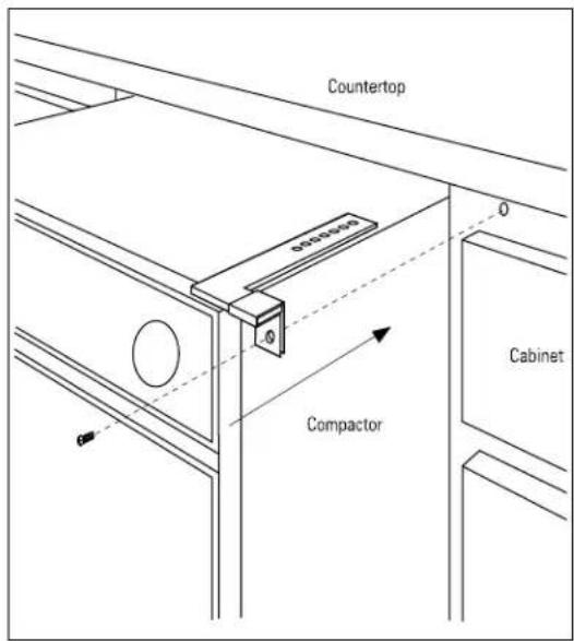
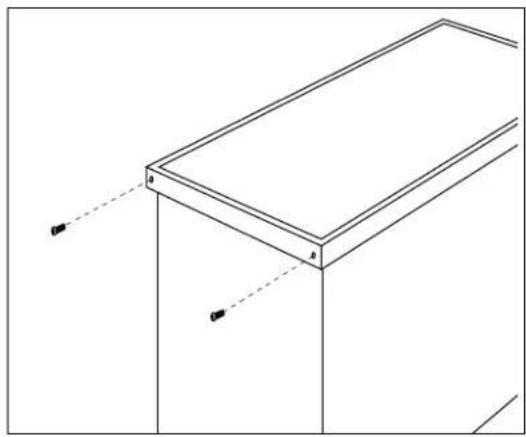
Technical line drawing of a mechanical assembly with an inset showing a close-up of a hexagonal bolt detail (no text or symbols)Step 5 Attach tip-over brackets
Position tip-over brackets on the top of the compactor. Match hole #3 of the bracket to the screw hole on the compactor (the 3rd hole on the bracket is the standard location). Attach tip-over bracket to compactor with one slotted head screw on each side.

text_image
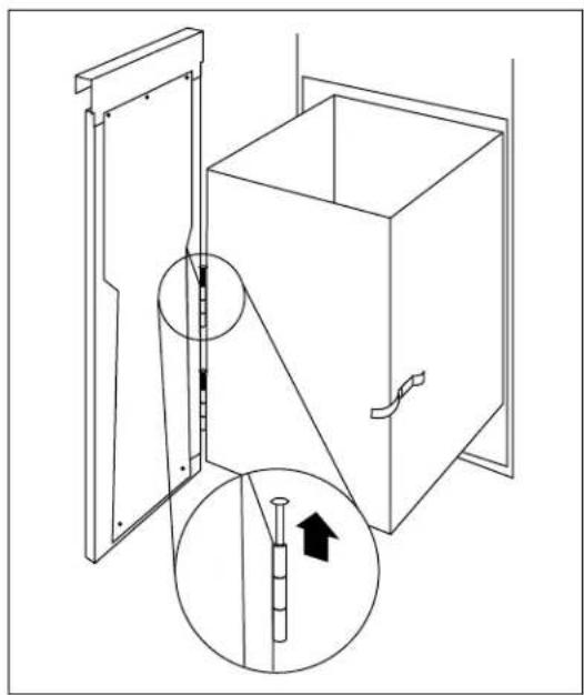
Compactor Top #7 #3 #1- Remove the compactor drawer for easier handling.
- Then position the compactor just in front of the cabinet opening.
- PLUG POWER CORD INTO THE WALL RECEPTACLE.
- Slide compactor back into cabinet opening.
Note: Make certain that the leveling feet caps are on the leveling feet and the power cable is not under compactor.
natural_image
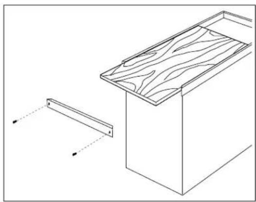
Line drawing of a simple office setup with a desk, cabinet, and storage unit (no text or symbols)The short leg of anti-tip bracket should be completely under the lip of the countertop but not so far back that the screws can't be put in. If the bracket is not in the proper location, pull the compactor back out far enough to get to the top screws and reposition the bracket to the appropriate hole.
Drill (4) 1/8" dia. x 1/2" deep pilot holes in the underside of the countertop at the location of the four holes in the short leg of the anti-tip bracket.
Caution: Do not drill up through the top of the countertop.
Secure anti-tip bracket to countertop with 4 Phillips head screws (supplied) on each side.

text_image
Compactor Top Countertop OverlapInstallation
Built-In Compactors
Step 5 (continued)
If the countertop cannot be drilled into, slip the 90° clips over the short leg of the bracket and screw into the face of the cabinet.
text_image
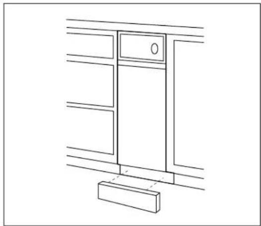
Countertop 0-100mm Compactor CabinetStep 6 Optional custom toekick
To install custom toekick (not supplied) measure the front of the compactor's adjustable base and use those dimensions to cut out your custom toekick. Secure as appropriate to installation.
Note: The custom toekick should be installed in such a manner that it can be removed if service is required.
natural_image
Line drawing of a cabinet or cabinet with a door and base, no text or symbols presentStep 7 Changing front panel (ZCG3300 and 3100 only)
Remove compactor drawer by pulling it out until it stops. Then lift the drawer to clear second stop and remove drawer. Place drawer on its back.
natural_image
Pure technical line drawing of a rectangular frame with two vertical supports and dashed alignment lines (no text or symbols)Procedure A
Reverse color panel
Remove the two screws in the bottom edge of the trim. Slide panel out, turn it over and slide back in. Reinstall trim.
Optional custom panels (ZCG3300 and 3100 only)
Procedure B
1/4" thick wood panel
Proceed as in "A" above, but discard the aluminum color panel and cardboard spacer. Slide 1/4" panel into trim. Reinstall trim.
natural_image
Technical line drawing of a wooden cabinet with a side panel and alignment indicators (no text or symbols)Procedure C
3/4" thick wood panel with supplied handle
- Pull the drawer out to stop position.
- Unlatch the drawer front by opening the clasp on the right side.
- While supporting the weight of the drawer front, remove the hinge pins on the left side.
natural_image
Technical line drawing of a cabinet with an open door and a magnified inset showing internal components (no text or symbols)Procedure C (continued)
- Lay drawer front face down on a flat surface.
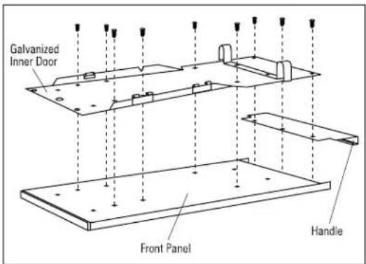
- Remove 9 screws which retain the front panel and handle.
- Save handle and galvanized inner door.
- Discard front panel with side trim.
- Place galvanized inner door onto the back side of the finished panel.
- Position the inner door 1/4" below the top of the finished panel and center, left to right.
- Use the inner door as a template. Drill 3 pilot holes in the top edge and 2 at the bottom, sized to match screws being used. (Screws are not provided)
Caution: Select screw length carefully to avoid penetration of the finished side. - Lift the top edge of the inner door and slide the handle between the inner door and the finished panel. Align the screw holes of the inner door and handle with pilot holes.
- Drive 2 screws loosely in the top. Align bottom holes, and check to be sure that the inner door is centered left to right over the finished panel. Drive 2 screws at bottom.
- Drive last screw at top, tighten all screws.
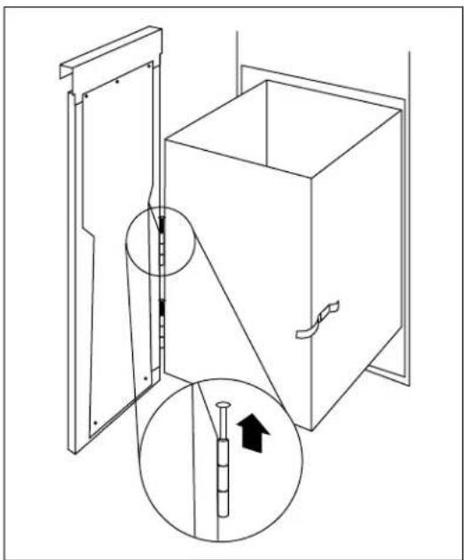
- Replace drawer front to drawer by re-installing the hinge pins. Swing door against drawer and secure with side clasp.
- Slowly push the drawer closed and check alignment of the panel.

text_image
Galvanized Inner Door Front Panel Handle
text_image
Galvanized Inner Door Top 1/4" Back Side Finished Panel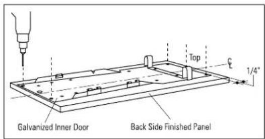
text_image
Galvanized Inner Door Back Side Finished Panel Top 1/4"
text_image
Galvanized Inner Door Back Side Custom Panel Handle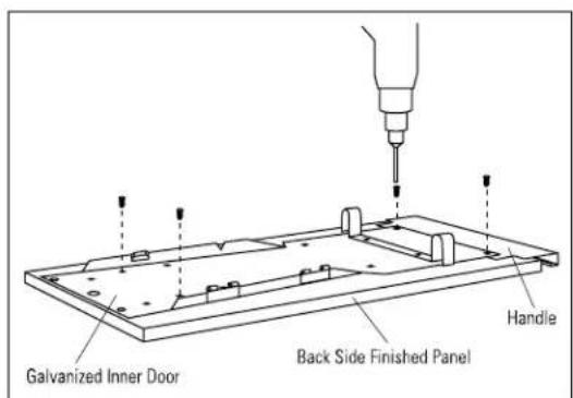
text_image
Galvanized Inner Door Back Side Finished Panel HandleProcedure D
3/4" thick wood panel with custom handle
- Pull the drawer out to stop position.
- Unlatch the drawer front by opening the clasp on the right side.
- While supporting the weight of the drawer front, remove the hinge pins on the left side.
natural_image
Technical line drawing of a cabinet with an inset showing a piston and arrow (no text or symbols)- Lay drawer front face down on a flat surface.
- Remove 9 screws which retain the front panel and handle.
- Save galvanized inner door.
- Discard front panel with side trim and handle.
text_image
Galvanized Inner Door Front Panel Handle- Place galvanized inner door onto the back side of the finished panel.
- Position the inner door 1-5/16" below the top of the finished panel and center, left to right.
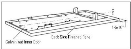
text_image
Galvanized Inner Door Back Side Finished Panel 1-5/16"- Use the inner door as a template. Drill 2 pilot holes near the top and 2 at the bottom, sized to match screws being used. (Screws are not provided)
- Drive 2 screws loosely into the bottom and 2 screw into the top. Check to be sure the inner door is centered left to right over the finished panel. Tighten screws.
Caution: Select screw length carefully to avoid penetration of the finished side.
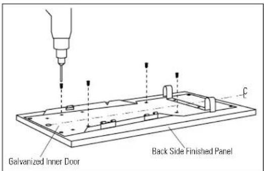
text_image
Galvanized Inner Door Back Side Finished PanelProcedure D (continued)
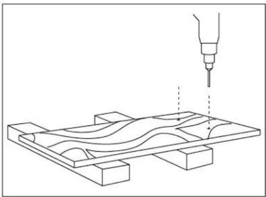
- Turn the panel over, appearance side up. Use wood blocks to support the inner door and prevent damage to the hinge and lock tabs.
- Drill pilot holes through the front of the custom panel and through the metal panel to match the chosen handles.
-
Secure handle to wood panel with screws (not supplied).
-
Replace drawer front to the drawer by re-installing the hinge pins. Swing door against drawer and secure with side clasp.
- Slowly push the drawer closed and check alignment of the panel.
natural_image
Technical line drawing of a mechanical assembly with a tool and wavy internal components (no text or symbols)
natural_image
Diagram of a wooden panel with internal wavy lines and a small inset showing a pin (no text or symbols)Note: While performing installations described in this book, safety glasses or goggles should be worn.
For Monogram* local service in your area, call 800.444.1845.
Note: Product improvement is a continuing endeavor at General Electric. Therefore, materials, appearance and specifications are subject to change without notice.

Monogram.®
Pub. No. 49-5778-4
Dwg. No. 165D4700P196
93042835C
10-03 JR
GE Consumer Products
General Electric Company
Louisville, KY 40225
© 2003 General Electric Company