HPT1230D - Cooker ILVE - Free user manual and instructions
Find the device manual for free HPT1230D ILVE in PDF.

User questions about HPT1230D ILVE
0 question about this device. Answer the ones you know or ask your own.
Ask a new question about this device
Download the instructions for your Cooker in PDF format for free! Find your manual HPT1230D - ILVE and take your electronic device back in hand. On this page are published all the documents necessary for the use of your device. HPT1230D by ILVE.
USER MANUAL HPT1230D ILVE
USER – Use and Maintenance
INSTALLER – Installation and maintenance
INDEX
4 IMPORTANT SAFETY WARNINGS
11 INSTRUCTIONS FOR USE
11 Use of the cooking hob
13 Correct use of burners
15 Correct use of the grills
18 Use of the gas fry-top
20 Use of the gas barbeque (optional)
21 CLEANING AND MAINTENANCE
21 Cleaning the appliance
22 Total black burners
23 INSTALLATION
23 Instructions
24 Built-in installation
25 Built-in tops' hole size
28 Electric connection
29 Gas connection and transformation
31 Adjustment and/or adapting to different types of gas
32 Gas regulation
33 Gas jets adjustment table
34 Replacement of the injectors
35 Cooking hob table
36 Adjustment of minimum
37 WIRING DIAGRAMS
37 Keys
39 TROUBLESHOOTING
39 Troubleshooting Guide
41 NOTES
Appliances' data
The data plate, as well as being on the cover, is also on the a pliance.
CAUTION
These warnings refer to different appliance models. Be sure that you have correctly identified the model that you possess (see the data plate).

These warnings are valid for the countries listed on the plate.
1 Read the instructions booklet carefully, before using the appliance. This contains very important informations concerning safety during installation, use and maintenance. The instructions booklet must be kept with care for later consultation and for the identification of the serial number.
2 The electrical safety of this appliance is only guaranteed if it is properly earthed as required by the regulations in force. It is fundamental to ensure that these regulations have been respected; if you are in doubt, call a skilled technician to have the electrical system checked in detail. The manufacturer does not accept any responsibility for damage caused by a bad earthing system.
3 Before connecting the cooker, check that the technical features on the data plate correspond perfectly with those of the electric system and of the gas mains. The installation / regulation must be made by qualified staff.
4 Check that air circulates freely around the appliance. This appliance is not connected to a combustion products evacuation device therefore the premises' ventilation system must be considered carefully and according to the rules in force.
5 When using gas appliances, heat and dampness are generated inside the premises. Good ventilation of the kitchen is required by: keeping the natural vents open or installing a mechanical ventilator (hood). Intensive and prolonged use of the appliance can make supplementary ventilation necessary: opening a window or increasing the power of the hood.
6 The power cable is supplied without a plug. To connect please refer to the "electric connection" paragraph. We advise not using adapters, multiple sockets or extensions.
7 Disconnect the power supply when the appliance is not used for some time, switch off the mains and turn off the gas.
8 When the electric cable is damaged, it must be replaced by calling an after saves service approved by the manufacturer.
9 The appliance must only be used for the purposes for which it was intended (cooking). Any other use (for example, heating a room) is incorrect and therefore dangerous. The manufacturer declines all responsibility for damage caused by similar incorrect uses.
10 The unit is not intended to be operated by an external timer or a separate remote control system.
11 The use of any electrical appliance requires that the following rules are respected:
A. never touch the appliance when you have wet or damp hands or feet;
B. never use the appliance in your bare feet;
C. avoid using extensions or, if this is inevitable, take all possible precautions;
D. Never pull on the electric cable to remove it from the power socket;
E. do not expose the appliance to weathering (rain, sun, etc.);
F. Be careful: the accessible parts may become very hot during use. Keep children less than 8 years old away from the cooker, if not continuously supervised. This appliance can be used by children from 8 years old and by persons with reduced physical, sensory or mental abilities otherwise with lack of experience and knowledge if they are adequately supervised or if they have been instructed on the safe use of the cooker and if they realise the relevant dangers. Children must not play with the cooker. Cleaning and maintenance must not be done by unsupervised children.
12 BE CAREFUL: some accessible parts may have high temperatures during use: keep children at a distance.
13 Before cleaning the appliance or carrying out maintenance, disconnect the power supply by removing the plug from the socket or switching the current off through the switch provided.
14 In the event of faults or malfunctions, switch off the appliance, turn off the gas tap and do not attempt to make any repairs; these must be carried out exclusively by an approved service centre. Always insist on original spare parts. Failure to follow these indications may endanger the safety of the cooker.
15 Never place unsteady or deformed pans on the burners or on the electric hotplates as they could overturn accidentally.
16 When the appliance is not in use, ensure that all the knobs are in the “●”/“○”/OFF position.
17 Never leave the hotplate switched on without a pan on it, otherwise it will reach a very high temperature quickly and the cooker or furniture in the vicinity could be damaged.
18 Some parts of the cooker, especially the electric hotplates, stay warm for a long time after use. Be careful not to touch them.
19 Do not keep below the cooker and do not use inflammable liquids (detergents, sprays, alcohol, petrol ...) near the cooker when it is switched on.
If using small electric appliances near the hob, be sure to prevent the electric cable from touching the appliance's hot parts.
In order to work properly, gas cookers must be installed in well ventilated premises. Ensure that installation is carried out according to the indications given in the "Installation" chapter.

22 The materials used in the construction of our electrical appliance are compatible with the environment and therefore recyclable. Packaging remains should not be left within the reach of children, but disposed of using specific recycling channels. The possibility of disposing of your equipment through your local retailer and/or town council should be investigated; remember to make your appliance unusable before scrapping it.
23 In case the tap is hard or precarious to turn, do not intervene on the tap but shut off the gas and have the authorised service centre intervene.
24 Do not modify or change the cooker.
25 Be careful: leaving the unguarded cooker with objects, fats and oils can be dangerous and can cause a fire.
26 The cooker must be used by responsible people. Be careful: the use of inappropriate or unsuitable protections can cause fires and / or damage.
27 Be careful: cooking with fat or oil can be dangerous or cause fires.
28 Be careful: fire danger: do not keep objects on co-oking surfaces.
29 Be careful: in the case of fire never attempt to extinguish a flame / fire with water, but turn the appliance off and cover the flame with a lid or with a fireproof cover.
30 Be careful: metal objects such as knives, forks, spoons or lids should not be placed on the cooker because they can get hot.
31 Be careful: do not use gas burners if the flame is unstable.
32 Ensure that the flame diffusers are properly positioned in their seats with their respective caps.
33 Do not leave the cooker unguarded during any cooking that can spit fats or oils.
34 Do not touch the appliance's heating elements when on. Let them cool before proceeding with any cleaning.
35 Food preparation in plastic or aluminium containers on hot cooking zones is forbidden just like the positioning on the cooking surfaces of plastic or aluminium foil objects.
36 Do not cover the burners or the hob with tinfoil.
37 Do not use the appliance's surface as a work top, sharp objects might scratch it.
38 Containers or grills must be positioned within the hob's perimeter.
39 Be careful: do not use frying pans, saucepans, grills or stones for grilling of a greater size than the maximum ones indicated for each single burner; above all they must not cover more than one burner at the same time. The heat accumulation might damage the cooker.
40 In case of liquid spilling over, remove it from the hob.
41 Do not place empty saucepans on the cooking areas.
INSTRUCTIONS FOR USE
Use of the cooking hob
WARNING
Keep children and the disabled away during operation. Do not use the appliance as a heating source.
General notes
To keep the appliance efficient and safe, maintenance must be entrusted to specialised technicians or to the after-sales service staff. Choose covered pans based on the quantity of food to cook.
IMPORTANT

text_image
c d e a b
text_image
b c d aPosition the brass flame distributor "d" (fig. C) properly.
For this, line up the tooth "e" on the flame distributor with thw hollow "b" of the aluminium cup "a".
Position the brass flamee distributor "b" properly.
For this, line up the tooth "c" on the flame distributor with the hollow "d" of the aluminium cup "a".
Lighting the burners
The index above the knobs fig.12a will help you to find the corresponding burner. Press the knob by turning it anticlockwise and bring it to the ignition position; keep the knob pressed for about 5 seconds so that upon its release the flame remains alight (in case of unsuccessful ignition repeat the operation).
Symbols

Function
Off
Maximum
Minimum
Index

natural_image
Simple line drawing of a circular object with internal markings and a small protrusion (no text or symbols)INSTRUCTIONS FOR USE Use of the cooking hob
Pots to be used according to the size of the burners

natural_image
Three identical stainless steel cooking pots on different heating platforms, no text or symbols visible| Burners ID | Diameter ∅ (cm) | |
| Medium SR 10/20 | ||
| Large R 20/24 | ||
| Fish burner P oven pans | ||
| Ring TC/DCC 22/28 | ||
| Dual ring DUAL 24/30 |
Igniting the Triple ring burner "DUAL"
Identify the knob with the help of the index placed at the knobs themselves. Press and turn the knob to the (maximum) symbol for 5 seconds. Once the burner is on, continuing to turn the knob anticlockwise leads to a first block of the knob that corresponds to the medium. Applying a slight force the first block is exceeded and the outer crown turns off leaving only the small central burner called AUXILIARY. To adjust the auxiliary burner to minimum, turn the knob anticlockwise until it stops. At this point, to turn the burner back on, turn the knob clockwise to the desired value.
Dual knob
Symbols

Function
Off
Maximum
Minimum
Index

natural_image
Simple circular diagram with a pointer and two dots, no text or symbols present
natural_image
Close-up of a gas stove burner with blue flame patterns (no text or symbols visible)
natural_image
Close-up of a gas stove burner with visible flames and smoke (no text or symbols)
natural_image
Close-up of a gas stove burner with blue flame patterns (no text or symbols visible)
natural_image
Close-up of a gas stove burner with blue flame and circular top (no visible text or symbols)INSTRUCTIONS FOR USE
Correct use of burners
Placement of the burners
BE CAREFUL: always check that the burners are correctly positioned, thus having a homogeneous and not noisy flame.
Burners
Right Wrong
Medium

natural_image
Close-up of a black circular object with a metallic base and perforated top, placed on a silver circular base (no text or symbols visible)
natural_image
Close-up of a metallic circular device with a black top and perforated lid, marked by a red arrow pointing to the base (no text or symbols visible)Large

natural_image
Top-down view of a black circular object with a metallic band and perforated top, placed on a silver plate (no text or symbols visible)
natural_image
Close-up of a perforated metal plate with a black top, placed on a silver base (no text or symbols visible)Dual ring

natural_image
Close-up of a metallic circular device with black and gold casing, possibly a lid or cover, against a plain background (no text or symbols visible)
natural_image
Close-up of a mechanical component with a perforated ring and metallic base, marked by red arrows (no text or symbols visible)Fish burner

natural_image
Exterior view of a modern office building (no signage)
natural_image
Close-up of a metallic mechanical component with red arrows pointing to features (no visible text or symbols)Always check that the screws below the burner are fixed.
INSTRUCTIONS FOR USE
Correct use of burners
| Positioning of the burners | BE CAREFUL: always check that the burners are correctly positioned, thus having a homogeneous and not noisy flame. | |
| Burners | Right Wrong | |
| Medium |  |  |
| Large |  |  |
| Dual ring |  |  |
| Fish burner |  |  |
Always check that the screws below the burner are fixed.
INSTRUCTIONS FOR USE
Correct use of the grills
Placement of the grills
BE CAREFUL: always check that the grills are properly positioned and facing the right way.
Internal grills hole measurement
FISH BURNERS RING (DUAL) LARGE MEDIUM

text_image
110mm 290mm
text_image
120mm
text_image
120mm
Different types of grills

natural_image
Exterior view of a stainless steel gas stove with two burners (no text or symbols visible)H30

natural_image
Four stainless steel gas lamps with black outlines and control knobs, arranged in a row (no visible text or symbols)H39P

natural_image
Front view of a stainless steel gas stove with a central rotary fan and side blades (no visible text or symbols)H30C

natural_image
Front view of a four-wet gas stove with three flanges and control knobs (no visible text or labels)H90CC
INSTRUCTIONS FOR USE
Correct use of the grills

natural_image
Four UK-style gas stove with four panes and control knobs (no visible text or labels)HP65

natural_image
Front view of a stainless steel gas stove with four panes and a central vent (no visible text or symbols)H70

natural_image
Exterior view of a gas stove with two flanges and control knobs (no text or symbols visible)HF40

natural_image
Modern stainless steel gas stove with four panes and vented grilles (no visible text or labels)H90P

natural_image
Front view of a gas stove with four panes and two side outlets (no visible text or labels)HF40D

natural_image
Exterior view of a stainless steel gas stove with six flanges (no text or symbols visible)H906

natural_image
Front view of a silver portable air conditioner unit with control panel and side grille (no visible text or symbols)HP45F

natural_image
Front view of a gas stove with four stoves and a central cylinder (no text or symbols visible)HP95P
INSTRUCTIONS FOR USE
Correct use of the grills

natural_image
Top-down view of a gas stove with four flanges, arranged with colorful chili peppers on the side (no text or symbols visible)HP95F

natural_image
Front view of a four-gas stove with four flanges and control knobs (no visible text or labels)HP1230

natural_image
Exterior view of a modern stainless steel gas stove with six identical fumes and blue flames (no text or symbols visible)HP1265

natural_image
Exterior view of a stainless steel gas stove with multiple cooktops and a tray of cutlery (no text or symbols visible)HP120
INSTRUCTIONS FOR USE Use of the gas fry-top
Instructions
The fry top consists of a stainless steel plate, suitable for contact with food [☐] with a uniform temperature of the cooking surface and with a very low heat dispersion. To use the appliance, light the flame underneath the plate by turning the corresponding knob (see "Burner ignition") and make sure the flame is present.
Position the knob at the maximum for about 10 minutes and wait for the plate to heat up. After this period of time, the plate is ready to start cooking.
By adjusting the flame, you will have no limit to your culinary imagination.
The position of the knob on the minimum allows slow or dietetic cooking while, for cooking meat, fish and vegetables, faster cooking is indicated. The fry top plate is also suitable for oriental dishes with an optional (lid) necessary for this type of cooking.
Some models are supplied with a spatula that will help you cooking and cleaning the plate.

natural_image
Technical line drawing of a rectangular electronic device with mounting holes and a side panel (no text or symbols)
text_image
B A CA = cooking area
B = drip tray
C = exhaust flue for combustion flame
INSTRUCTIONS FOR USE Use of the gas fry-top

text_image
A B C$$ \mathbf {A} = \text { Max } $$
$$ \mathbf {B} = \text { Med } $$
$$ \mathbf {C} = \text { Min } $$
Pic. 1

natural_image
Illustration of a metal spatula with black handle and silver blade (no text or symbols)Pic. 2
| Dish | Knob posit. (pic.1) | Time min. |
| Eggs B 2 | ||
| Sliced aubergines (0.5 cm thick) | B 9/13 | |
| Sliced potatoes B 5/7 | ||
| Sliced courgettes B 3/5 | ||
| Fish (sea bream weighing about 200 g) | B | 15 |
| Hamburger B 10 | ||
| Beefsteak B 3 | ||
| Porterhouse (2 cm thick) A 5 |
Cleaning and care of the Fry-Top
It is recommended to clean the plate thoroughly at the end of each coking session. With the plate hot and the flame at minimum, remove the cooking residue using the scraper provided (pic. 2). Pour a little water onto the plate and, still using the scraper, continue cleaning the plate. Once the water has completely evaporated, repeat the same operation even several times until the desired result is obtained. It is extremely important to clean the plate when it is quite hot.
The black enamel flue may be cleaned with a soft cloth soaked with a solution of lukewarm water and ammonia. Rinse and dry after cleaning.
INSTRUCTIONS FOR USE Use of the gas barbeque (optional)
Instructions
Replace the flame spreader A with the flame spreader protected for barbecue B. Before refitting the barbecue plate, make sure you have positioned the flame spreader correctly and carry out an ignition test.
To use the appliance, light the flame underneath the plate by turning the corresponding knob (see "Burner ignition") and make sure the flame is present. Position the knob at the maximum for about 10 minutes and wait for the plate to heat up. After this period of time, the plate is ready to start cooking. Place the burner at minimum and place the dishes on the plate. Consult the cooking table for general information on timing. You may find cooking times different from those shown in the table. This is completely normal, as times change according to the quantity and temperature of the food, the type of gas and, of course, your personal taste.

natural_image
Black-and-white photo of a rectangular tray with striped pattern and two small figures on the side (no text or symbols visible)
text_image
Technical diagram showing a heat exchanger or cooling unit with labeled components A and B, indicating flow direction.Barbeque cleaning
Allow the barbecue to cool before cleaning. Use a slightly abrasive sponge or a brush with brass bristles following the satin finish of the plate. It is important to remove the incrustations that form between one lamella and the other. It is advisable to clean the plate after each cooking. Like all barbecues, the plate with use loses its brilliance and can create dark halos. Once cooled, the fireplace is cleaned with a soft cloth soaked in a solution of warm water and ammonia.
| Dish | Knob posit. (pic.1) | Time min. |
| Sliced aubergines (0.5 cm thick) | B 3/15 | |
| Sliced potatoes B 5/7 | ||
| Sliced courgettes B 4/6 | ||
| Fish (sea bream weighing about 200 g.) | A | 10 |
| Hamburgher A 10 | ||
| Beefsteak B 3 |
CLEANING AND MAINTENANCE
Cleaning the appliance
Warning | Before carrying out any cleaning operation, disconnect the appliance from the power supply and close the general gas cock to the appliance.Cleaning the worktop: clean the hob only after cooling. Periodically the burner cups, the enamelled grills, the enameled lids, and the flame spreader must be cleaned with lukewarm soapy water, rinsed and dried well. Any liquid overflowing from the pans must always be removed with a rag. Cleaning the enamelled parts: To maintain the characteristics of the enamelled parts, it is necessary to clean them frequently with soapy water. Never use abrasive powders or metal pads. Avoid leaving acid or alkaline substances (vinegar, lemon juice, salt, tomato juice, etc.) on the enamelled parts and wash when the enamelled parts are still hot. |
| Cleaning of stainless steel parts | Clean the parts with warm water and non-corrosive liquid detergent and then dry them with a soft cloth or microfibre. The brilliance is maintained by periodic cleaning with special products normally available on the market. Never use abrasive powders. |
| Food stains or residues | Absolutely avoid using steel sponges and sharp scrapers to avoid damaging the surfaces.Use normal, non-abrasive products, possibly with the aid of wooden or plastic tools. Rinse thoroughly and dry with a soft cloth or a microfibre cloth. Avoid leaving residues of sugary food (such as jam) inside the appliance as they could damage the enamel in the appliance. |
Cooking hob grills | Remove the grids and clean them in warm water and a non-abrasive detergent. Carefully remove any encrustations. Dry them and place them on the hob.The continuous contact of the grids with the flame can cause an alteration of the enamel in the vicinity of the areas exposed to heat. This is a completely natural phenomenon that does not affect the functionality of this component at all. |
| Igniters and thermocouples | For good operation, the ignition plugs and thermocouples must always be well cleaned. Check them frequently and if necessary clean them with a damp cloth. Any dry residues must be removed with a wooden toothpick or a needle. |
Flame distributor rings and covers | The flame-spreader crowns and the lids are removable for easy cleaning. Wash them in hot water and non-abrasive detergent. Carefully remove any encrustations and wait until they are perfectly dry.In the event of a malfunction, make sure that the holes in the outer crown are always perfectly clean.The use of the dishwasher for cleaning grills, flame spreaders and lids is not recommended |
CLEANING AND MAINTENANCE
Total black burners
Total black burners coated with treatment nanotechnology
In order to preserve the quality of the coating, some cleaning and washing methods are recommended:
- Allow the product to cool to room temperature before cleaning. It is advisable not to immerse it in cold water when it is still hot.
- Wash with warm water, and with a minimum of neutral detergent. Rub with a cloth, preferably in natural cellulose, or a non-abrasive sponge.
- Do not use powders, iron wool, abrasive cloths or sponges.
- Do not let food burn on the burner. In the event of surface stains / stains may appear. These traces do not alter the functionality of the product, and in some cases they can be eliminated with this procedure: immerse the product in hot water, with detergent, rub gently with a cloth, preferably in natural cellulose, in any case do not use cloths or abrasive sponges. For more resistant stains it is advisable to heat white vinegar and rub as indicated above.
- Avoid leaving the burners in contact with food for a long time, especially if acids, such as tomato sauce.
- Avoid contact with metal objects, if it is the case to use wooden or plastic objects.
- Avoid washing in the dishwasher, a part of the product is not coated and would be irreparably damaged.
- In the event of a malfunction, make sure that the holes in the outer crown are always perfectly clean.

natural_image
Close-up of a black and white circular device with a hexagonal top and perforated base (no visible text or symbols)INSTALLATION Instructions
Installation instructions
This appliance complies with the following directives
DIRECTIVE EU2002/96/EEC
LOW TENSION DIRECTIVE EEC 2014/35/EU
GAS DIRECTIVE 2009/142/EC
ELECTROMAGNETIC COMPATIBILITY DIRECTIVE 2014/30/EU
REGULATION No. 1935/2004 (contact with foods)
Installation must only be made by qualified personnel in the respect of regulations for permanently ventilated premises according to UNI 7129 01/02/04 - 7131.
Ventilation of the premises
This appliance is type "A" and not to be joined to a combustion products' expelling device but must be installed under a hood or another smoke extraction system in compliance with the rules in force. The knowledge and consultation of the rules is critical for a qualified installer. As an indication, remember that the air necessary for burner combustion is 2m3/h for each kW of nominal power installed (see plate). If the appliance is used intensively and for a prolonged time, supplementary ventilation may be necessary; in this case open a window or increase the power of the mechanical extractor hood.
Fitting the cooking hob onto the base unit with door
The unit must be made in such a way that the flames are not blown out if the doors are opened or closed rapidly. The bottom of the cooking hob must not be subject to depression or pressure when the doors are opened or closed. We advise working as shown in the figure (A). The panel under the hob must be easy to remove for maintenance purposes.

text_image
1 2 20 mmFig. A
INSTALLATION Built-in installation
Built-in installation
All the built-in tops are designed to be mounted on furniture with surfaces of any material and with a thickness varying from 3 to 4 cm. To avoid excessive overheating of the side and rear walls, it is recommended to drill the hole for the surface recessed, at a minimum distance of 45-50 mm, respecting the measurements shown in the table (pic. 1). To avoid infiltration of liquids under the worktops, it is essential to apply the appropriate healing (C), which is supplied with the top. Fixing to the cabinet is done with the brackets that are supplied with the appliance (pic 2a, 2b, 2c).
For counter tops (HP665, HP965, HP1265, HAP95, HAP125, HP90, HP120 ...), the support surface must have the surface base equal to the appliance and a strength such as to support a weight of at least 100 kg.

text_image
50 A B Fig. 1Pic. 1

text_image
CPic. 2a


Pic. 2b
(mod. HP65, HP75, HP95, HP125)
Our appliances can be fitted as:
• freestanding, Class 1
- fitted between units, Class 2/1
• built-in into units, Class 3
The minimum distances from the furniture must be:

natural_image
Close-up of a mechanical component with a tool and metallic bracket (no visible text or symbols)• between top and overhead hood 650 mm
• between top and overhead cabinet 700 mm
• between top and back wall 50 mm
• between top and overhead side wall 50 mm
• between top and lower wall 20 mm
- the built-in top fitted onto a base unit with door must be installed according to picture A
- the cooking hobs for supported appliances must support a weight of at least 100 kg
• the furniture must resist at least up to 120°C
• the thickness of the top must be at least 3 cm
The built-in appliances must be inserted (see pic. 1), fixed (see pic. 2a, 2b) with the brackets, applying the appropriate seal (C) between the furniture and the appliance. The application of the hob in the furniture can also be done with an oven below paying attention to the path of the power cable that must not come into contact with hot surfaces (50 °C beyond the environment).
INSTALLATION
Built-in tops' hole size
MOD. H30 - H30P - H30C | MOD. HP75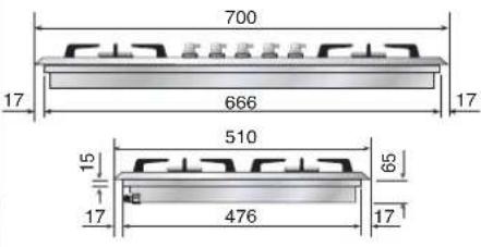 672x490 380x490 672x490 380x490 | MOD. HP45F |
MOD. H36 | MOD. HP65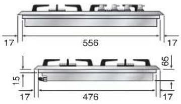 570x490 835x475 - *H90=50 570x490 835x475 - *H90=50 | MOD. H39 |
MOD. H38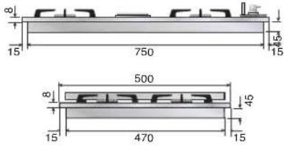 755x475 755x475 | MOD. HP95 MOD. XLP90 860x490 860x490 | MOD. HP95 MOD. XLP90 875x580 875x580 |

text_image
MOD.HAP125 117 80 130 20 65 65 80 177
MOD. HF40

text_image
200.40 mm 985 100 365 102.5 Ø22 100
text_image
38.75 35.75 31.75 32.75 485 365 305 365 170 166.5 90 308.5 388.5 156.5 (20)MOD. HAP95

text_image
520 890 520 550 130 210 890130 x 50
MOD. HP90

text_image
600 900 185 40MOD. HP120

text_image
1200 600 185 40MOD. HP665 - HP965 - HP1265

text_image
85 650 42,5 65 70 G Gas connection Electrical connection 650 600 (P665) / 900 (P965) / 1200 (P1265)MOD. HC60

text_image
502 14,5 66 426 39,8 10
text_image
582 18,5 545 18,5Built-in tops' hole size: 555 x 475
MOD. HC70

text_image
502 14,5 66 426 41 10
text_image
702 78,5 545 78,5Built-in tops' hole size: 555 x 475
MOD. HC70SD

text_image
502 14,5 41 66 426 10
text_image
702 56 590 56Built-in tops' hole size: 640 x 475
MOD. HC90

text_image
502 15 66 426 39 10
text_image
862 56 750 56Built-in tops' hole size: 835 x 475
INSTALLATION
Electric connection

The appliances are prepared for connection to the voltage shown on the data plate.
Before connecting the appliance to the mains check that:
- the electromagnetic switch or the socket are able to support the appliance's load (see data plate);
- the power supply system must have an efficient earth.
The appliance is supplied with a cable but without a plug: the connection must be made taking into account that the green-yellow cable is the earth conductor 12 and it must never be interrupted.
For direct connection to the mains, it is necessary that:
- the relief valve and domestic system can support the equipment's load (see data plate)
• the power supply system must have an efficient earth - the socket or omnipolar switch, with a minimum 3 mm contact opening, must be easily reached once the appliance has been installed a mains shut-off must be incorporated in accordance with installation rules.

The green-yellow earth cable must never be interrupted even by the switch. The power cable must be routed in such a way that it does not come into contact with surfaces that have a temperature greater than 50^ C above room temperature. If cable replacement is necessary contact the after-sales service.
| Power (230V) (240V) | ||
| Hotplate (∅ 115) 550 W | 600 W | |
| Hotplate (∅ 115) 920W | 1000 W | |
| Hotplate (∅ 115) 1380 W | 1500 W | |
| Barbeque 1900 W | 2070 W | |
| Barbeque* 2650 W | 2880 W |
* HP965B, HP1265B, HP90B, HP120B
INSTALLATION
Gas connection and transformation
Gas connection
(UNI CIG 7129/7131)
The appliances must be connected to the gas network with rigid or flexible metal pipes (maximum length 2 meters) suitable for gas appliances. The connecting pipes and their maximum lengths must meet current standards (UNI CIG 9891), be replaced before the deadline (if specified on the pipe) and be connected to the appliance by means of fittings:
A) Directly on the ISO R228 connection (seal with ISO R228 gasket), if the pipes allow it, see figure 3
B.1) If the connection must be direct (right-left-down), the accessory must be inserted (fig. 4a - fig. 4b).
B.2) Use the gasket (ISO R228) to seal between the tube and the ramp. 4a
B.3) The tapered fittings with the seal on the thread must be used for sealing on the thread (ISO R7) (fig. 4b)
B.4) To improve the seal, it is possible to use a mastic suitable for GAS.
When the gas is taken from a cylinder, the appliance must be powered with a pressure regulator compliant with the UNI-CIG 7432 standard:
- with continuous flexible stainless steel wall pipes according to UNI-CIG 9891, with a maximum extension of 2 meters and sealing gaskets according to UNI 9264.
Precautions for using the product with gpl gas
The gas taps fitted in your kitchen must work with liquid gas of controlled quality, supplied at the proper nominal pressure. This pressure must be guaranteed by a special certified pressure regulator. The use of gas coming from uncertified sources and/or the improper use of the GPL cylinder as well as the relative regulator, can invalidate the product's guarantee. It is especially necessary to avoid all the situations that could pollute the gas with residues and impurities that, when introduced into the gas circuit, can irreparably damage the control components such as taps and thermostats. It is recommended to:
- use only GPL cylinders coming from official retailers and authorised by the various manufacturers;
- use the cylinders until empty without inclining or overturning them;
- carry out regular cleaning of the filter at the pressure regulator inlet;
WARNING

When the connection is made, it is recommended to check the connections' seal with special foams (NO FLAMES).
IMPORTANT
Periodically check the gas connection pipe's good condition and replace it when there are signs of anomalies.
INSTALLATION
Gas connection and transformation

text_image
Sealing ringPic. 3

text_image
Sealing ring JunctionPic. 4a

text_image
Sealing ring ——JunctionPic. 4b

Any adjustment, maintenance, etc... must be made by an authorised technician after having disconnected the appliance from the mains and shut off the gas supply.
INSTALLATION
Adjustment and/or adapting to different types of gas

Adjustment and/or adapting to different types of gas
The hobs are delivered to operate as indicated on the data plate. If a transformation should be necessary, proceed as described in the next paragraph.
Injector replacement and air adjustment for models:
H30 - H360 - H380 - H39 - HF40 - HP45F - HP65 - HP75 - HP95 - HAP95 - XLP90F - HP1230 HP125 - HAP125 - HP665 - HP965 - HP1265 - HP90 - HP120
- Remove the grill and the burners from the worktop.
- Unscrew the screws marked with the arrows that fix the worktop to allow it to be raised, pic. 5, pic. 5a, pic. 5b.
- Unscrew venture pipe screw "F" (pic. 6, pic. 7) and open completely the air regulator "R".
- Unscrew the injectors (U) and replace them with those suitable for the gas in use and supplied with the appliance. Refer to table on page 33.
- Air adjustment is made by the special regulator "R" based on the "X" values shown in table on page 33, opening of primary air. When adjustment is over block the regulator "R" with screw "F".
Pic. 5

natural_image
Close-up of a kitchen appliance with a black lid and a red circle highlighting a component, no visible text or symbols.Pic. 5a

natural_image
Close-up of a mechanical component with three red-circled holes and small components, mounted on a metallic circular base (no visible text or symbols)INSTALLATION
Gas regulation

natural_image
Top-down view of a rectangular electronic device with red circles highlighting four corner points (no text or symbols present)Pic. 5b

text_image
R U F XPic. 6

text_image
U X RPic. 7
Examples of air regulation (for information)
| A | B |
Flame with too much air:small and drawn.Decrease the "X" amount | Flame with scant air:Irregular with yellow points.Increase the "X" amount. |
| C |
Correct flame:Blue |
Gas jets adjustment table
| SR | R | P | C | DUAL | DUAL PIANI "PH" | ||||
| Qmax kW | 1,80 | 2,60 | 3,10 | 4,30/3,40^(3) | 4,50/3,60^(3) | 5,00/3,60^(3) | |||
| Qmin kW | 0,40/0,53^(1)/0,45^(2) | 0,62/0,80^(1)/0,70^(2) | 1,00/1,30^(1)/1,10^(2) | 1,70 | 0,37 | 0,37 | |||
 ∅ mm ∅ mm | G30/G31 28..30/37 mbar | 0,62 | 0,78 | 0,82 | 1,00 | 0,35 | 0,92 | 0,35^(4) | 1,00^(4) |
| G30/G31 50 mbar | 0,55 | 0,68 | 0,75 | 0,90 | 0,33 | 0,82 | 0,33^(4) | 0,88^(4) | |
| G30 37 mbar | 0,62 | 0,74 | 0,82 | 0,92 | 0,35 | 0,92 | 0,35^(4) | 0,92^(4) | |
| G20 20 mbar | 0,97 | 1,17 | 1,30 | 1,50 | 0,55 | 1,40 | 0,55^(4) | 1,50^(4) | |
| G20 25 mbar | 0,87 | 1,10 | 1,17 | 1,35 | 0,55 | 1,35 | 0,55^(4) | 1,40^(4) | |
| G25 20 mbar | 1,05 | 1,30 | 1,45 | 1,65 | 0,62 | 1,60 | 0,62^(4) | 1,70^(4) | |
| G25 25 mbar | 0,97 | 1,23 | 1,35 | 1,55 | 0,62 | 1,50 | 0,62^(4) | 1,60^(4) | |
| G2.350 13 mbar | 1,35 | 1,65 | 1,85/1,80^(4) | 2,20 | 0,78 | 2,20 | 0,78^(4) | 2,40^(4) | |
| G25.1 25 mbar | 1,05 | 1,25 | 1,35 | 1,60 | 0,62 | 1,55 | 0,62^(4) | 1,60^(4) | |
| G110 8 mbar | 1,90 | 2,45/2,30^(4) | 3,00/2,60^(4) | 3,30 | 1,10 | 3,20 | 1,10^(4) | 3,20^(4) | |
| G120 8 mbar | 1,75 | 2,30/2,20^(4) | 2,60/2,40^(4) | 3,20 | 1,05 | 3,00 | 1,05^(4) | 3,00^(4) | |
 by-pass ∅ mm by-pass ∅ mm | G30/G31 | 0,30/0,32^(4) | 0,38/0,40^(4) | 0,50/0,52^(4) | 0,61/0,64^(4) | 0,27 | 0,60 | 0,27^(4) | 0,60^(4) |
| G20 | REG | REG | REG | REG | REG | REG | REG | REG | |
| G25 | REG | REG | REG | REG | REG | REG | REG | REG | |
| G2.350 13 mbar | REG | REG | REG | REG | REG | REG | REG | REG | |
| G110/G120 | REG | REG | REG | REG | REG | REG | REG | REG | |
 X= mm X= mm | G30/G31 | 2,00 | 6,00 | 20,00 | 20,00 | 20,00 | 20,00 | 20,00 | 20,00 |
| G20 | 2,00 | 3,00 | 3,00 | 6,00 | 20,00 | 4,00 | 20,00 | 4,00 | |
| G25 | 2,00 | 3,00 | 3,00 | 4,00 | 20,00 | 4,00 | 20,00 | 4,00 | |
| G2.350 13 mbar | 0,00 | 3,00 | 5,00 | 5,00 | 20,00 | 4,00 | 20,00 | 10,00 | |
| G110/G120 | 0,00 | 0,00 | 0,00 | 3,00 | 1,00 | 0,00 | 1,00 | 1,00 | |
| (1)=DE AT | (2)=PL | (3)=G110/G120 | (4)=RUBINETTO CUCINE | ||||||
INSTALLATION
Replacement of the injectors
HC60 - HC70 - HC90
- Remove the grill and the burners from the hob.
- SR - R - P burners: unscrew injectors "U" using a 7-mm spanner (fig. 8) and replace them with those for the new gas according to table on page 35.
- DCC - Dual burners: unscrew the 2 screws "P" and remove cover "C" fig. 9. unscrew injectors "U" using a 7-mm spanner (fig. 10, fig.11) and replace them with those for the new gas according to table on page 35.

natural_image
Technical line drawing of a mechanical assembly with no visible text or symbolsPic. 8

text_image
P C PPic. 9

natural_image
Close-up of a mechanical component with a central hub and metallic parts (no visible text or symbols)Pic 10

natural_image
Close-up of a mechanical component with a metal tool inserted, showing internal parts and no visible text or symbols.Pic. 11
Cooking hob table
| SR R P DCC | DUAL | ||||||
| Qmax kW | 1,80 / 1,70^(5) | 3,00 / 2,80^(5) | 3,10 / 2,6^(5) | 4,20^(4) / 4,30 / 3,40^(3) / 3,10^(5) | 4,50 / 3,80^(3) / 3,5^(5) | ||
| Qmax g/h 131 218 225 | 305^(4) / 313 | 327 | |||||
| Qmin kW | 0,40 / 0,51^(1) / 0,45^(2) | 0,60 / 0,76^(1) / 0,66^(2) | 1,20 / 1,57^(1) / 1,35^(2) | 1,70 / 2,20^(1) / 1,90^(2) | 0,30 | ||
| Qmin g/h | 29 / 37^(1) / 33^(2) | 44 / 55^(1) / 48^(2) | 87 / 114^(1) / 98^(2) | 124 / 160^(1) / 138^(2) | 22 | ||
 | G30/G31 28..30/37 mbar 0,68 / 02 | 22 0,85 / 0222 0,86 / 02 | 22 1,05 / 0222 0,44 / 022 | 0,97 / 0222 | |||
| G30/G31 50 mbar 0,58 / 0264 0,75 / 0265 0,75 / 0222 0,83 | / 0315 0,43 / 0102 0,75 | 0315 | |||||
| G30 37 mbar 0,62 / 0222 0,80 / 02 | 22 0,82 / 0222 1,00 / 02 | 22 0,41 / 0222 0,95 / 022 | |||||
| G31 27,5 mbar AUSTRALIA 0,70 | / 0222 0,92 / 0222 0,95 / | 0222 1,12 / 0222 0,50 / | 0222 1,10 / 0222 | ||||
| G20 20 mbar | 0,97 / 0211 | 1,30 / 0103 | 1,30 / 0222 | 1,50 / 1048 | 0,70 / 0101 | 1,42 / 1048 | |
| G20 10 mbar AUSTRALIA | 1,18 / 0222 1,55 / | 0222 1,55 / 0222 1,95 / | 0222 0,80 / 0222 1,75 / 0222 | ||||
| G20 25 mbar 0,91 / 0211 | 1,10 / 0210 1,23 / | 0222 1,50 / 0103 0,65 / 01 | 01 1,40 / 0103 | ||||
| G25 20 mbar 1,00 / 0210 1,34 / 03 | 32 1,42 / 0222 1,64 / 03 | 32 0,72 / 0306 1,50 / 0332 | |||||
| G25 25 mbar 0,98 / 0210 1,26 / 03 | 32 1,28 / 0332 1,48 / 03 | 32 0,75 / 0306 1,40 / 0332 | |||||
| G25.3 25 mbar | 0,94 / 0210 1,26 / | 0332 1,26 / 0332 1,48 / | 0332 0,75 / 0306 1,40 / 0332 | ||||
| G2.350 13 mbar | 1,26 / 0210 1,64 / | 0332 1,70 / 0332 2,10 / | 048 0,91 / 0210 2,10 / 1048 | ||||
| G25.1 25 mbar | 0,98 / 0210 1,25 / | 0309 1,28 / 0332 1,52 / | 0332 0,71 / 0306 1,50 / 0332 | ||||
| G150.1 8 mbar | 1,90 / 0224-2 | 2,75 / 0224-3 | 2,70 / 0224-6 | 3,50 / 00003 | 1,45 / 00004 | 3,50 / 00003 | |
| G110 8 mbar | 1,90 / 0224-2 | 2,75 / 0224-3 | 2,70 / 0224-6 | 3,50 / 00003 | 1,45 / 00004 | 3,50 / 00003 | |
| G30/G31 | 0,30 | 0,38 | 0,56 | 0,66 | 0,24 | 0,65 | |
| G20 | REG | REG | REG | REG | REG | REG | |
| G25 | REG | REG | REG | REG | REG | REG | |
| G2.350 13 mbar REG | REG REG | REG REG REG | |||||
| G110/G120 | REG | REG | REG | REG | REG | REG | |
| (2)=PL (3)=G110/G120 (4)=HC70, HC90C (5)=G150.1 | |||||||
INSTALLAZIONE
Adjustment of minimum

When installing the appliance, we recommend checking that the hob's burner minimum has been properly adjusted: a proper adjustment is that when passing from the maximum position to the minimum position, the flame is reduced, stable and homogeneous.
If the flame on minimum is incorrect or if the gas has been changed, adjustment must be carried out as follows:
- Light one burner at a time and turn the flame up to maximum.
- Remove the knob of the corresponding gas tap.
- Turn the tap to minimum position.
- Using a small flathead screwdriver, unscrew, turning to the left, to increase the flame, or screw to the right to decrease it: the by-pass to be adjusted is indicated by the figure B1 and B2.
- If a liquid gas is used (Butane-Propane), the screw (by-pass) must be fully screwed in.

natural_image
Diagram showing a mechanical component with rotational motion arrows, no text or symbols presentPic. B1

text_image
by-passKeys
| 00 Black | |
| 11 Brown | |
| 22 Red | |
| 33 White | |
| 44 Yellow | |
| 45 Yellow-Green | |
| 55 Grey | |
| 66 Blue | |
| AA Electrical ignition transformer | |
| C Switch | |
| F Phase | |
| K1 | Earth wire for terminal board |
| K2 | " " lower resistance |
| K3 | " " for oven fan |
| K4 | " " circular resistance |
| K5 | " " upper resistance |
| K6 | " " oven lamp 1 |
| K7 | " " oven lamp 2 |
| K8 | " " rotisserie |
| K9 | " " cooling fan |
| K10 | " " selector |
| K11 | " " oven thermostat |
| K12 | " " programmer/timer |
| K13 | " " grill |
| K14 | " " el. hotplate |
| K15 | " " frame |
| K16 | " " barbecue |
| K17 | " " fryer |
| L1 | Oven lamp |
| L2 | Oven lamp |
| M | Terminal board |
| MA | Electrical ignition microswitch |
| MD | Grill microswitch |
| MG | Rotisserie |
| MP | Door microswitch |
| N | Neutral |
| P | Timer/Programmer |
| P | Timer/Clock |
| PE | Electric hotplate |
| R1 | Upper heating element |
| R2 | Lower heating element |
| R3 | Grill heating element |
| R4 | Circular heating element |
| R5 | Barbecue heating element |
| R6 | Fryer heating element |
| RE | Energy regulator |
| S1 | Oven warning light |
| S2 | Mains power warning light |
| S3 | Grill warning light |
| S4 | Cooling fun warning |
| S5 | Barbecue warning light |
| S6 | El. hotplate warning light |
| S7 | Turnsplit warning light |
| S8 | Residual heat warning light |
| S9 | Fryer warning light |
| SP | Sparking plug |
| T | Grill thermostat |
| TF | Oven thermostat |
| TR | Fryer thermostat |
| TS | Safety thermostat |
| TT | Cooling fan thermostat |
| V | Oven fan |
| VT | Cooling fan |
WIRING DIAGRAMS
§ = only models with electric barbecue

text_image
MA MA MA MA MA AA 11 66 11 RE 00 S5 P1 2 00 R5 11 P2 4 00 M N F K1 K15 K16 45 SPModels H392..., H391...

text_image
MA MA MA MA MA 11 AA 66 SP M N F 45 K1 K14 K15 S6 C P3 5 33 11 P1 2 55 1 44 3 33 P2 4 22 1 2 4 3 PE C P3 5 33 11 P1 2 55 1 44 3 33 P2 4 22 1 2 4 3 PETROUBLESHOOTING Troubleshooting Guide
- During the warranty period repairs can only be carried out by the authorized After-Sales Service.
- Before repairing, disconnect the appliance from the mains, ie, disconnect the power cord or unscrew the fuse.
- Unauthorized interventions and repairs may cause electrocution or short circuit, so do not perform them. Leave this work to authorized technicians.
- In the case of minor disturbances you can try to solve the problem by following the instructions.
- The assistance service during the warranty is not free, if the device does not work for incorrect use.
- The elimination of faults or complaints, which were caused by use or incorrect installation, will not be repaired under warranty. Warranty costs will be charged to the user.
Below you will find some advice on rectifying some common problems.
| PROBLEM | POSSIBLE CAUSE | ELIMINATION |
| The flame is not uniform. | Gas regulation not suitable. | The gas regulation must be controlled by an expert |
| The flame changes suddenly. | The burner parts are not positioned correctly. | Position the burner parts correctly. |
| To light the burners, keep the ignition knob pressed for longer. | The burner parts are not positioned correctly. | Position the burner parts correctly. |
| After ignition the flame goes out. | The knob was not pressed long enough or was pressed too gently. | Keep the knob pressed longer, before releasing it, press strongly. |
| The grill in the burner area has changed color. | A natural phenomenon due to the high temperature. | Clean the grill with metal cleaning detergent. |
| Electrical operation is generally disturbed. | Igniter or terminal block damaged. | Check the ignition and / or the terminal block and replace it if it is damaged. |
| The electric ignition no longer works. | Food or detergent residues between the ignition electrode and the burner. | Clean carefully between the ignition electrode and the burner. |
| The burner lids are dirty. | Normal dirt. | Clean the lids with metal cleaning detergent. |
If the problem persists despite observing the instructions above, call the authorised after-sales service.