SCM-MFD-LC-KIT - Unspecified Shadow-Caster - Free user manual and instructions
Find the device manual for free SCM-MFD-LC-KIT Shadow-Caster in PDF.

User questions about SCM-MFD-LC-KIT Shadow-Caster
0 question about this device. Answer the ones you know or ask your own.
Ask a new question about this device
Download the instructions for your Unspecified in PDF format for free! Find your manual SCM-MFD-LC-KIT - Shadow-Caster and take your electronic device back in hand. On this page are published all the documents necessary for the use of your device. SCM-MFD-LC-KIT by Shadow-Caster.
USER MANUAL SCM-MFD-LC-KIT Shadow-Caster
text_image
shadow-caster® MARINE LEDs MULTI-ZONE LIGHTING CONTROLLER shadow-caster.com LED LIGHTING shadow-wine® MFD-COMMUNICATIONS BRIDGE SCM-MFD-BRIDGE
text_image
shadow-net® TECHNOLOGY ENABLEDTABLE OF CONTENTS
SCM-MFD-LC-KIT BOX CONTENTS 3
COMPATIBILITY & OPTIONS 3
SCM-MFD-LC-KIT OVERVIEW 4
SCM-MFD-LC-KIT TYPICAL WIRING DIAGRAM 4
INITIAL ONBOARDING STEPS....5
SHADOW-CASTER® LIGHTINGHOMESCREEN....7
CONFIGURING ZONES....7
USING SCENES....8
CONFIGURING PROGRAMS......8
MUSIC SYNC CONFIGURATION....9
CONNECTING THE SCM-MFD-BRIDGE & INITIAL SYNCING....9
INSTALLATION 10
ADDING ADDITIONAL REMOTES AND MULTI-FUNCTION DISPLAYS ....11
SHADOW-NET ^® DEVICES ....11
OPTIONAL PARTS 11
BEST PRACTICES FOR MITIGATING NOISE ISSUES ....11
CONNECTING STEREO INPUT FOR STEREO MUSIC SYNC INPUT 11
TROUBLESHOOTING 12
SCM-MFD-LC-KIT BOX CONTENTS
• SCM-MZ-LC Multi-Zone Lighting Controller
• SCM-MFD-BRIDGE Multi-Function Display Bridge
- 8 x SS316 Pan Head 8 x ^3/4 " Mounting Screws
• Installation & Operation Manual
• Warranty and Registration Information
PRODUCT SERIAL NUMBER
You can add your product serial number here for warranty and product registration purposes.
The serial number is located on a white label inside the housing of the SCM-MZ-LC.
My Serial Number:
COMPATIBILITY & OPTIONS
| Manufacturer | Optional IP67 Shadow-Caster® Cable | Required Cable from Manufacturer |
| GARMIN | SCM-MFD-Cable Garmin | PN: 010-10550-00 (6ft Cable)PN: 010-10551-00 (20ft Cable)PN: 010-10552-00 (40ft Cable)PN: 010-10580-10 Isolator |
| SIMRAD | SCM-MFD-Cable NavicoSCM-MFD-Cable Navico-SCM-MFD-Cable Navico | PN: 000-14552-001 (1.5m Cable) |
| LOWRANCE | SCM-MFD-Cable Navico PN: 000-14552-001 (1.5m Cable) | |
| B&G | SCM-MFD-Cable Navico PN: 000-14552-001 (1.5m Cable) | |
| Raymarine | - PN: A80247 (2m Cable) | |
| FURUNO | - | - |
SCM-MFD-LC-KIT OVERVIEW
The Shadow-Caster® MFD Lighting Control Kit (SCM-MFD-LC-KIT) includes the Multi-Zone Lighting Controller (SCM-MZ-LC) and the MFD Bridge (SCM-MFD-BRIDGE).
The SCM-MZ-LC Lighting Controller supplies fused power connection for up to 4 separate zones of user selectable RGB or RGBW lighting. It can receive an analog music input, and also broadcasts multiple channels of digital commands to other devices on the Shadow-NET® Bus (orange and yellow wires).
The SCM-MFD-BRIDGE provides a control interface to the Multi-Zone Lighting Controller through an Ethernet connected MFD (Multi-Function Display) or other connected device.
The control interface steps you through selecting and naming a desired number of control zones. The setup process will also identify all additional Shadow-NET® connected devices and assign them to the desired lighting zone. The zones can then be assigned to a desired color and brightness or even configured for an active lighting program. The program is saved as a unique 'lighting scene' for easy recall.
At initial power up the Shadow-NET® bus will broadcast messages to tell connected devices to turn off. This allows these devices to be used without a dedicated switch. When the SCM-MZ-LC controller receives a command to turn on, it will send a corresponding command to devices connected on the Shadow-NET® bus.
SCM-MFD-LC-KIT TYPICAL WIRING DIAGRAM

text_image
10-30V DC Power Source SCR-24-CC Underwater Lights Defaults to Zone 1 SCM-DLX-CC or SCM-DL-CC Down Lights Defaults to Zone 2 SCM-SL-CC Spreader Lights Defaults to Zone 3 12V DC Power Source 3.5mm Female Audio Jack Shadow-NET RGB Zone 1 RGB Zone 2 RGB Zone 3 RGB Zone 4 4 x Channels of RGB Lighting (supports up to 15A per channel) Note: Lighting connected to outputs 1-4 of the SCM-MZ-LC will always correspond to zones 1-4 in the lighting application. Shadow-Net® connected lights can be assigned to any zone 1-6. SCM-MFD-BRIDGESCM-MZ-LC shadow-carrier LED LIGHTING AMBI COMMUNICATIONS BRIDGE 5CM-MFD-BRIDGESCM-MZ-LC MFDUSING THE INTERFACE
INITIAL ONBOARDING STEPS
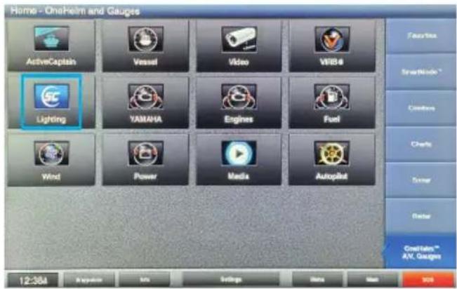
- Select the Shadow-Caster Lighting app icon from your MFD home screen.
text_image
Home - Onshore and Gauges ActiveCaptain Vessel Video WBS4 Lighting YAMAHA Engines Fuel Wind Power Media Autopilot Features SmartWindow * Comforters Charts Sensor Faster Coatings™ AV. Gauges 12:38A Regulator MIL Settings Data Map 905- Upon opening the lighting app you should see the welcome screen.
Press the NEXT button → to initiate the system and proceed through the onboarding process detailed in the following steps.

text_image
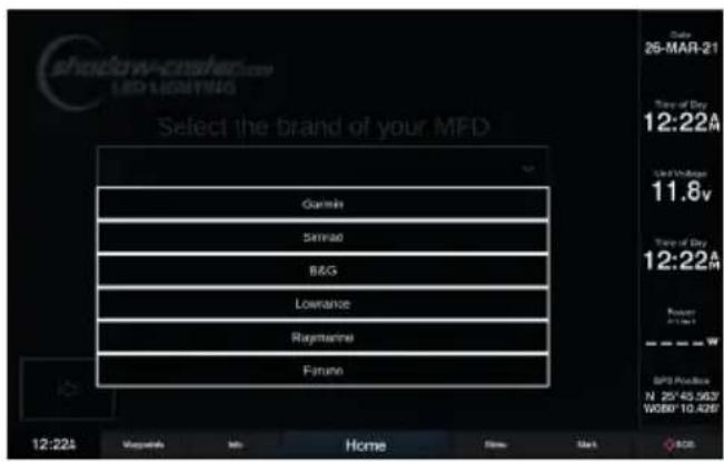
shadow-caster.com LED LIGHTING Welcome to Shadow Caster Lighting 12:22A Magazines Help Home Home Mark GPS Display N 25°45.5637 W080°10.4297 Date: 26-MAR-21 Time of Day: 12:22A Light Undernoon 11.9v Time of Day: 12:22A Power Current GPS Display N 25°45.5637 W080°10.4297- Select the brand/manufacturer of your chosen MFD as shown here.
Once selected press NEXT button → to confirm.
text_image
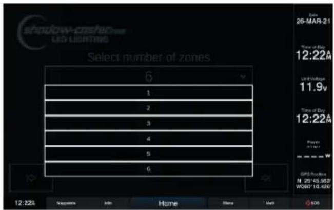
shadow-crushede LED LIGHTING Select the brand of your MFD Gamini Simmao B&G Lowrance Rigmaster Furano 12:22A Magazine Home New Mark 26-MAR-21 Time of Day 12:22A Used Minutes 11.8v Time of Day 12:22A Return Slight SPD Release N 25°45.56'7 W080°10.42'6- Select the number of lighting zones required for your system.
Once selected press NEXT button ↗ to confirm.
Note: RGB zones 1-4 are statically assigned to their corresponding zone but Shadow-NET ^® lights can be assigned to any zone number.
text_image
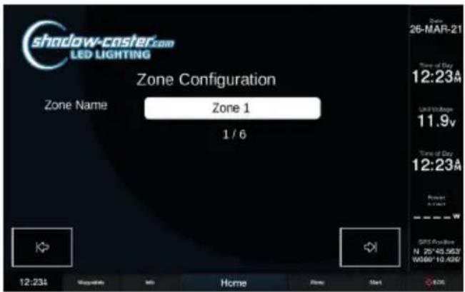
shadow-crashed LED LIGHTING Select number of zones 6 1 2 3 4 5 6 Date: 26-MAR-21 Time of Day 12:22A Unit Duration 11.9v Time of Day 12:22A Power W GPS Profile: N 25°45,5637 W060°10,430° 12:22A Parameters Info Home None Mark EOS- Step through the individual lighting zones and give a unique name. This can also be done later through the Config Menu.
Once selected press NEXT button → to confirm.
text_image
shadow-caster.com LED LIGHTING Zone Configuration Zone Name Zone 1 1 / 6 Date: 26-MAR-21 Time of Day: 12:23A Limit Voltage: 11.9V Time of Day: 12:23A Power: 5kW SPS Available N 25*43.5637 W080*10.4390- Please make sure that all of the lighting devices on the network are powered and connected. The system will go through and identify everything that is connected.
Once selected press NEXT button → to confirm.

text_image
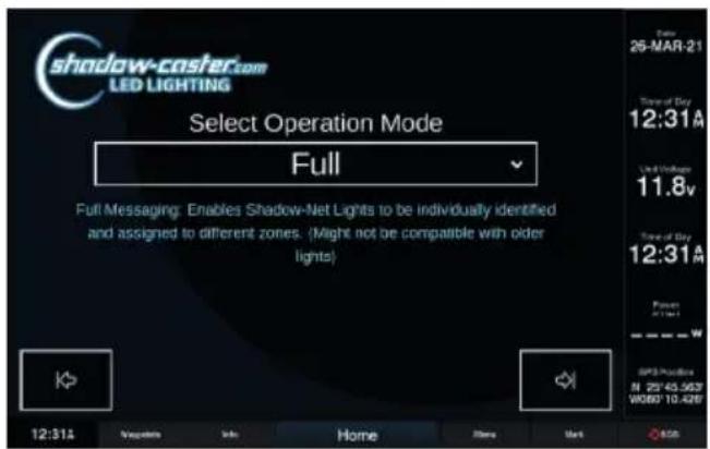
shadow-caster.com LED LIGHTING Light Configuration Make sure all lights are connected and powered on. During unboarding, please power all connected devices. Properly attached lights will receive Shadow-NET commands to go dark, until uniquely identified. 12:23A Mapleums Info Home Home Mark 26-MAR-21 Time of Day 12:23A Time of Day 11.8v Time of Day 12:23A GPS Position N 25°45.56'7 W800°10.42'7- Select the required Operation Mode:
Full Mode (Recommended)
Full Mode allows individual control of all devices connected to the Shadow-NET bus. This is the recommended setting.
Global Mode
Global Mode only allows control of everything on the bus as one channel. This is only required for working with certain older technology underwater lights (pre 2018).
Once selected press NEXT button → to confirm.
text_image
shadow-caster.com LED LIGHTING Select Operation Mode Full Full Messaging: Enables Shadow-Net Lights to be individually identified and assigned to different zones. (Might not be compatible with older lights) 12:31A Message Info Home Store Mark 26-MAR-21 Time of Day 12:31A Used Windows 11.8v Time of Day 12:31A Power (1:4) SPS Protection N 25°45.56'7 W080°10.42'9- Once all the devices are found by the system, They can be identified by clicking "Identify". All connected lights will turn off, and the light being identified will flash white slowly.
Once identified, set the lights to their desired zones.
Once selected press NEXT button → to confirm.

text_image
shadow-caster.com LED LIGHTING Device Configuration Device Name Single Zone Controller [97] Zone Zone 1 Firmware 104 Identify 1 / 1 12:33A Copyrights Info Home None Mark 25-MAR-21 Time of Day 12:33A Unit Block 11.8v Time of Day 12:33A Power W/10-4260 GPS Provider N 25°45.963" W080°10-4260SHADOW-CASTER® LIGHTING HOME SCREEN
This is the default screen by clicking on the Shadow-Caster® app icon after the onboarding process has been completed.
Scenes can now be easily recalled by pressing a scene button.
There are several preset scenes already configured.

text_image
Zone 1 Off Zone 2 Off Zone 3 Off Zone 4 Off Zone 5 Off Zone 6 Off Scenes Blue White Red Green All Off Rotate All Dimmed RYGCBM Blue White Music shadow-castler Care LED LIGHTING Config Program Help Save GARDMIN™ 12:22A Supplements Info Home None Mark 26-MAR-21 Time of Day 12:22A LED Lighting 11.8v Time of Day 12:22A Power 21kW SPS Position N 25V 45,5627 W080 10,426An example of the Home Screen after the 'RYGCBM' scene is recalled is shown below.
Note: 'RYGCBM' is short for Red/Yellow/Green/Cyan/Blue/Magenta.
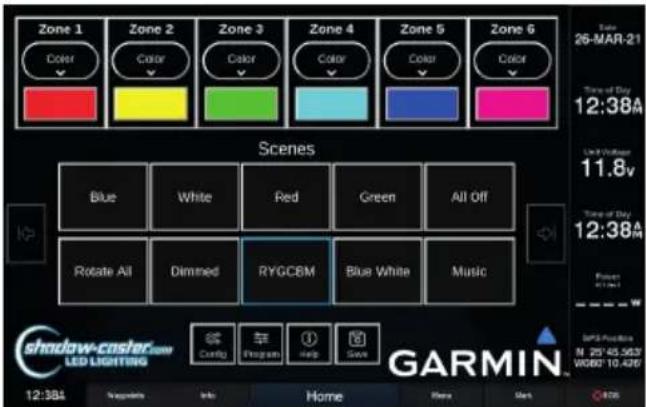
text_image
Zone 1 Color Zone 2 Color Zone 3 Color Zone 4 Color Zone 5 Color Zone 6 Color Scenes Blue White Red Green All Off Rotate All Dimmed RYGCBM Blue White Music Shadow-coslar.com LED LIGHTING Config Program Help Save GARMIN™ 12:38A Supplifts Info Home Here Gate Time of Day 12:38A Time of Day 12:38A SPS Position N 25°45.563" W060°10.426"CONFIGURING ZONES
In the zone control box, there are two buttons.
Pressing the top button reveals a drop down selection with three options: turn the zone off; select color and brightness control; or select the currently active program.

text_image
Zone 1 Color Off Color Switch 1 Zone 2 Color Switch 3 Zone 3 Color Switches Zone 4 Color Switch 4 Zone 5 Color Switch 5 Zone 6 Color Switch 6 Multi Change Scenes Blue White Red Green All Off Rotate All Dimmed RYGCBM Blue White Music Config Program Help Save GARMINThe lower button indicates the current color and brightness or the current program. To change the color, press the current color button and the color scroll bar will pop up.
Slide the color bar to select any color, or select the intensity slider to change the brightness.
Note: Multiple zones can be selected at the same time to allow multiple lighting zones to be controlled and and changed together.

text_image
Zone 1 Zone 2 Zone 3 Zone 4 Zone 5 Zone 6 Zone 1 Zone 2 Zone 3 Zone 4 Zone 5 Zone 6 Select Color Select Intensity Blue White Blue White All Diff Shadow-casier LED LIGHTING GARMINUSING SCENES
A 'Scene' is a way to have all of the zones in your configuration set to a predetermined color, intensity or lighting program.
New scenes can be saved and existing scenes can be customized or removed to fit your preferences.
SCENE OPTIONS CONFIGURATION
Assign a Powerup Scene for the lighting as soon at it receives power.
Assign a Startup Scene for the lights to go to as soon as the application opens up in the browser.
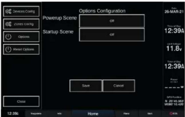
text_image
Devices Config zones config Options Reset Options Options Configuration Powerup Scene all Startup Scene all Save Cancel Close 12:39A Settings Info Home Plans Mark OCS Date 26-MAR-21 Time of Day 12:39A Up to Power 11.8v Time of Day 12:39A Power W SPX Position N 25°45.563" W080° 10.425"DELETING A SCENE
Press and hold a scene button to delete it.
Note: Long press functions are not supported in all Multi-Function Displays (MFDs).
UPDATING SCENES
Simply save over a scene name to update it.
SAVING A SCENE
Once all lighting zones are configured as desired, press SAVE and a window will pop up with a text box.
CONFIGURING PROGRAMS
These are accessible by clicking on the PROGRAM button.
MULTI-COLOR CHANGE PROGRAM CONFIGURATION
Select Color Sequence pattern.
Select Intensity level.
Select the Speed of rotation.
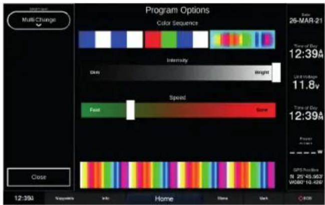
text_image
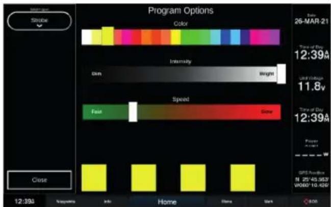
Program Options Color Sequence Intensity Dark Weight Speed Fast None Close 12:39A Sequence Info Home Home Mark Date: 26-MAR-21 Time of Day 12:39A Use Timeless 11.8v Time of Day 12:39A Power A: 0.0001 GPS Position N 25°43.56'2 V080°10.42'0 ©201STROBE PROGRAM CONFIGURATION
Select the desired color.
Then select Intensity (brightness) and Speed (rate of strobe).
text_image
Program Options Color Intensity Dim Weight Speed Fast Close Time of Day 12:39A Used Time 11.8v Time of Day 12:39A Power GPRS Position N 25°43.56'2' W060°10.42'2' Close 12:39A Solutions Info Home Here Mark C:00Select Type of Sync:
Single
Lights illuminate on a 'single' selectable color and pulse with the amplitude of the music.
Multi
Lights cycle through all available colors of at a fixed rate, but similar to Single mode, pulse with the amplitude of the music.
Falloff
Intensity of lights increases with the beat, and then falls off at a fixed rate.
Frequency
Drives colors based on the frequency content of the music. Provides the best music sync functions.

text_image
Music Program Options Single Multi Falloff Frequency Sensitivity Lower Lower Sample Rate Higher Close 12:39A Newsprint Info Home Share Mark Date 26-MAR-21 Time of Day 12:39M Last Time 11.8v Time of Day 12:39M Power 0.0000 GPS Provider N 25745.5637 W080* 10.4260OPTIMIZING MUSIC SYNC
- Turn music to typical listening volume, and press PAUSE on your stereo system. This will provide the lighting controller with an input signal representative of the audio system background noise.
- Adjust the sensitivity down 1 step at a time until the lights do not blink or flicker - this sets the system sensitivity to just above the audio systems noise floor.
- Resume music. The lights should now be changing in sync with the music input.
CONNECTING THE SCM-MFD-BRIDGE & INITIAL SYNCING
The SCM-MFD-BRIDGE is designed to automatically detect the brand of MFD it is connected to and establish a connection. Once the onboarding process is complete, and this information is verified, this step will not have to be repeated.
If the system does not establish a connection at initial startup:
CYCLE THE POWER OF JUST THE MFD BRIDGE, BY REMOVING THE 4 PIN CONNECTOR AND WAITING 10 SECONDS, AND THEN RECONNECT.
If the SCM-MFD-BRIDGE is moved from one brand display to another, a factory reset must be initiated on the screen prior to disconnecting.
Once the SCM-MFD-BRIDGE is properly connected, the Shadow-Caster® app icon will appear on the home screen or gauges accessories scene. Simply click on this icon to open the application.
Note: In the case of Raymarine MFDs, this icon is already there and not an indication of connectivity.
INSTALLATION
SCM-MZ-LC INSTALLATION
Central mounting locations under the helm areas or in the bilges are acceptable.
- Orient the cable glands facing down or to the side so that they do not collect water.
- Cinch cable glands as tightly as possible and fill unused glands so that the box is water tight.
- Use the included four 8 x 34 " SS pan head screws for mounting.
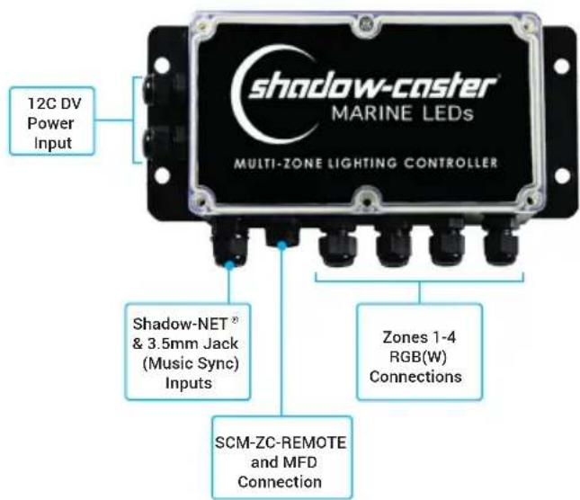
SCM-MFD-BRIDGE CONNECTIONS
text_image
12C DV Power Input shadow-caster® MARINE LEDs MULTI-ZONE LIGHTING CONTROLLER Shadow-NET® & 3.5mm Jack (Music Sync) Inputs Zones 1-4 RGB(W) Connections SCM-ZC-REMOTE and MFD ConnectionSELECTING RGB OR RGBW LIGHTING
Set the RGB(W) dip switch within the SCM-MZ-LC, depending on whether a zone is using RGB or RGBW lighting, from left to right, as follows:.
| Switch 1 2 3 4 | ||||
| ↑ | ZONE 1RGB | ZONE 2RGB | ZONE 3RGB | ZONE 4RGB |
| ↓ | ZONE 1RGBW | ZONE 3RGBW | ZONE 3RGBW | ZONE 4RGBW |
SCM-MZ-LC POWER REQUIREMENTS
See the Shadow-Caster ^® wire awg recommendations for detailed calculations. It is very important to have sufficient gauge wire feeds for RGB lighting.
It is recommended to separate feeds for lighting and for sensitive stereo power feeds with direct runs to the battery or a heavy gauge distribution point.
The SCM-MZ-LC will support 15 amps per zone. For a total of 60 amps in the entire box. The SCM-MZ-LC comes with 10 amp fuses installed.
The SCM-MZ-LC will work in 12V or 24V systems. Please note that 12V or 24 compatible RGB(W) products should be used depending on the application.
SCM-MFD-BRIDGE INSTALLATION
Central mounting locations under the helm areas or in the bilges are acceptable.
- Orient the cable glands facing down or to the side so that they do not collect water.
- Cinch cable glands as tightly as possible and fill unused glands so that the box is water tight.
- Use the included four 8 x 34 " SS pan head screws for mounting.
SCM-MFD-BRIDGE CONNECTIONS

text_image
Power (12V-30V) & Shadow-NET® Connection SD Card Slot The SD Card slot can be used to store XYZ Ethernet Connection Provides data connection to Mult-Function Display (MFD)RECOMMENDED WIRE GAUGES
Scan the QR Code or click here to view our recommended wire gauge chart.

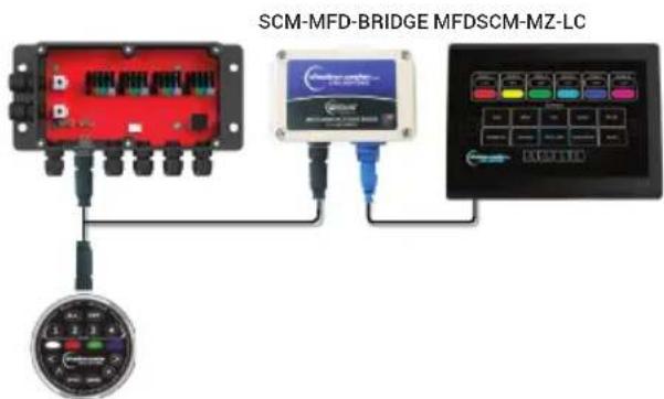
ADDING ADDITIONAL REMOTES AND MULTI-FUNCTION DISPLAYS
Additional SCM-ZC-REMOTES can be added to your installation with our Y-cable and 1m, 2m & 4m extension cables. See Optional Parts section below for details.
text_image
SCM-MFD-BRIDGE MFDSCM-MZ-LCSCM-ZC-REMOTE
SHADOW-NET ^® DEVICES
Connect Shadow-NET ^® enabled devices to the orange and yellow Shadow-NET ^® wires coming from the Multi-Zone Lighting Controller.
As soon as the Multi-Zone Lighting Controller receives power, multiple channels of digital messages start broadcasting on these wires. These messages allow Shadow-NET® enabled devices to be connected without a switch. Initially these commands are for attached lights to turn off. As soon as a command is given to the Multi-Zone Lighting Controller to go to a color, these attached devices will receive a message to go to the corresponding color and brightness.
Please note that different products are pre-programmed to respond to a certain channel. For example, Underwater Lights respond to Zone 1, Down Lights respond to Zone 2 and Spreader Lights respond to Zone 3.
OPTIONAL PARTS
• SCM-ZC-REMOTE Additional Remote Control
• SCM-SCNET-01 1meter Cable
• SCM-SCNET-02 2 meter Cable
• SCM-SCNET-04 4 meter Cable
• SCM-SCNET-Y Y Cable
BEST PRACTICES FOR MITIGATING NOISE ISSUES
Noise interface is common in systems with RGB lighting controls and amplified stereo systems. The advanced circuitry in the lighting controller does everything possible to protect from this.
Utilizing installation best practices will further mitigate these issues.
- Make sure to supply ample gauge power and separate distribution points from stereo power.
- Run RGB power wires as far as possible from the speaker feeds for the stereo. Run separate bundles where possible.
CONNECTING STEREO INPUT FOR STEREO MUSIC SYNC INPUT

flowchart
graph TD
    A["Stereo"] --> B["Coil"]
    C["Amp"] --> D["RCA (Phono) Cables & Splitters"]
    B --> E["Coil"]
    D --> F["Coil"]
    E --> G["To 3.5mm Female Audio Jack Input"]
    F --> G
TROUBLESHOOTING
MFD CONNECTION TROUBLESHOOTING
MY SYSTEM IS NOT CONNECTING:
Remove 4 screws on top of SCM-MFD-BRIDGE. Verify that the blue power light is on. This indicates a bad connection on the 4 pin cable from the lighting controller
Verify that the red and green communication lights are coming on and blinking. This will verify that the Ethernet connection is good, and communication is established.
MUSIC SYNC NOT WORKING
Verify that an appropriate 3.5mm stereo jack is being used and that there is a usable signal.
If a separate output zone is used, verify that the output is enabled and the output is set to a usable volume.
It is not recommended to use a subwoofer output, as certain sync modes require the full audio range.
MY SYSTEM HAS A "BOOT LOADER ERROR"
This is typically a problem with multi-screen installation and indicates that a POE isolator is needed.
SCM-MZ-LC NOT LIGHTING UP
When power is first applied to the lighting controller, the box will flash blue very briefly.
Once it receives a valid control input from a connected controller it will stay blue continuously. If it is not lighting up please double check for correct orientation and reseat the SC-NET cable.
SHADOW-NET® LIGHTS WILL OCCASIONALLY LOCK UP AND STOP RECEIVING MESSAGES
This indicates that there is a noise issue on the Shadow-NET® communication lines. Typically this is caused by insufficient gauge wire feeding one or more Shadow-NET® connected lights.
MY SHADOW-NET® LIGHTS STAY ON
If the connected Shadow-NET ^® lights are not turning off at initial power up then there is a challenge with the Shadow-NET ^® connection.
Check the orange and yellow wire connections are not reversed and are fully connected.
AUG21
DESCRIPTION
Control all of your marine lighting through your vessels touch screen interface and Shadow-Caster ^® 's easy to use SCM-MFD-LC-KIT (Multi-Function Display – Lighting Controller). Our unique system provides color, brightness, and multiple fade, strobe and music sync modes for up to 6 zones. Simply plug into your system's network interface and step through the on-screen setup. There is no additional software to install or complex configuration. The Shadow-Caster ^® Lighting Controller is compatible with most major MFD manufacturers including Garmin ^™ , Simrad, Lowrance ^® , B&G, Raymarine ^® and Furuno. Our SCM-MFD-LC-KIT is also compatible with all standard RGB and RGBW lighting.
FEATURES
- No software to download, simply plug into your display's network to access the system
- No extra power switches required. Our system will control all on/off power requirements for the lighting including optional Shadow-NET® lights
- Easy to use graphic interface
- Simply connect Shadow-NET® devices including Shadow-Caster® underwater lights or downlights and assign them to a zone
-
Compatible with all standard RGB and RGBW lighting
-
On screen setup allows you to configure and name up to 6 separate lighting zones, including, underwater lights, accent lights, and speaker lights
• Control color and brightness for each zone
• Control speed and color sequence for fade and strobe
• 4 different music sync modes - Endless lighting "scenes" can be configured and easily recalled
SPECIFICATIONS
- 4 individually fused 15 amp RGBW lighting connections
- Compatible with 12/24 volts systems
• 3.5 mm female audio connection input for music sync
• IP65 washdown rated enclosures
• Color coded connections make for easy installation - On-board indicator lights for system diagnostic
- Up to 6 zones of control
- Custom configurations available for boat builder applications
Contact Shadow-Caster® support for more details
• IP protocol for standard network interfaces as well all other applications
INCLUDES
• Multi-Zone Lighting Controller (SCM-MZ-LC)
• MFD Communications Bridge (SCM-MFD-BRIDGE-STANDARD)
- Standard ethernet cable which provides compatibility with most systems (Manufacturer adapter may be required - see chart)
- Mounting hardware
- 1 meter Shadow-NET® communication cable
PN: SCM-SCNET-01
- Quick start guide
• Standard 2 year warranty
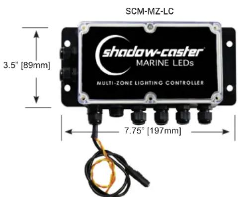
text_image
SCM-MZ-LC 3.5" [89mm] shadow-caster® MARINE LEDs MULTI-ZONE LIGHTING CONTROLLER 7.75" [197mm]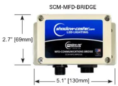
text_image
SCM-MFD-BRIDGE shadow-casher.com LED LIGHTING 2.7" [69mm] MFD-COMMUNICATIONS BRIDGE SCM-MFD-BRIDGE 5.1" [130mm]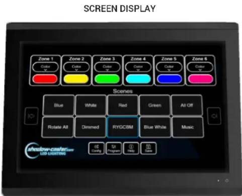
text_image
SCREEN DISPLAY Zone 1 Color Zone 2 Color Zone 3 Color Zone 4 Color Zone 5 Color Zone 6 Color Scenes Blue White Red Green All-Off Rotate All Dimmed RYGCBM Blue White Music Shadow-color LED-CLASSED Help Help Help Config Program Help Save
Designed & Manufactured
in Clearwater, FL
© 2021 Shadow-Caster® LEDs. All Right Reserved.
SHEDOLIGCainer | 2060 Calumet Street | Clearwater, FL 33765
p: +1 727.474.2877 e: info@shadow-caster.com w: shadow-caster.com
COMPATIBILITY AND CABLE REQUIREMENTS
| MANUFACTURER | OPTIONAL IP67 SHADOW-CASTER CABLE | REQUIRED CABLE FROM MANUFACTURER |
| GARMIN ^ | SCM-MFD-Cable-Garmin | PN: 010-10550-00 (6ft Cable) |
| Opt: 010-10551-00 (20ft Cable) | ||
| Opt: 010-10552-00 (40ft Cable) | ||
| PN: 010-10580-10 Isolator | ||
| SIMRAD | SCM-MFD-Cable-Navico | PN: 000-14552-001 (1.5m Cable) |
| LOWRANCE ^TM | SCM-MFD-Cable-Navico PN: 000-14552-001 (1.5m Cable) | |
| B&G | SCM-MFD-Cable-Navico | PN: 000-14552-001 (1.5m Cable) |
| Raymarine ^TM | —— | PN: A80247 (2m Cable) |
| FURUNO | —— | —— |
NOTE: Limitations and exclusions may still apply to compatibility.
OPTIONAL SHADOW-NET® CABLES
| SCM-SCNET-022 Meter Cable | SCM-SCNET-044 Meter Cable | SCM-SCNET-YY Cable for Adding SCNET Control Devices |
ADDITIONAL SHADOW-NET ^® DEVICES
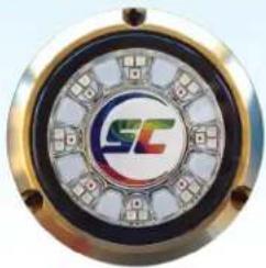 |  | 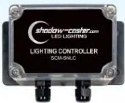 |  |
| SCR-24-CCFull Color Underwater LED Light | SCM-10-CC4 Color Underwater LED Light | SCM-SNLCAdditional RGB Controller | SCM-DL-CCFull Color Overhead Lighting(available in white or black) |
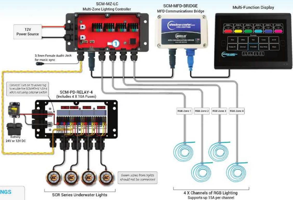
Standard Layout
SCM-MFD-LC-KIT & SCM-PD-RELAY-4 with SCR Underwater Lights & 4 Zones of RGB Lights

HOW TO OPERATE
5 independent on/off switches activate the zones independently of the MFD controls.
When switch is activated, the zone will turn to white.
Control: Momentary push button to change color and control brightness.
MFD control will override all switches.
RECOMMENDED WIRE GAUGES
Scan the QR Code or click here to view our recommended wire gauge chart.

text_image
12V Power Source 3.5mm Female Audio Jack for music sync SCM-MZ-LC Multi-Zone Lighting Controller SCM-MFD-BRIDGE MFD Communications Bridge Multi-Function Display Zone 1 Zone 2 Zone 3 Zone 4 Zone 5 Zone 6 LED LIGHTING Shadow-Coster MTD COMMUNICATIONS BRIDGE Multi-Function Display Blue Black Filter Green Black Filter Redra PS Correct White Blue SCB SCB SCB SCB SCB SCB SCB SCB SCB SCB SCB SCB SCB SCB SCB SCB SCB SCB SCB SCB SCB SCB SCB SCB SCB SCB SCB SCB SCB SCB SCB SCB SCB SCB① SCM-MZ-LC DIP SWITCH SETTINGS (from left to right counting up)
| 1 | 2 | 3 | 4 | |
| ↑ | Zone 1 RGB | Zone 2 RGB Zone | 3 RGB Zone 4 RGB | |
| ↓ | Zone 1 RGBW Zone | Zone 2 RGBW Zone | 3 RGBW Zone 4 RGBW |
REVISED
March 17th 2021
Shadow-Caster® LED Lighting | 2060 Calumet St. | Clearwater, FL 33765
p: 1+727.474.2877 | e: info@shadow-caster.com | w: Shadow-Caster.com
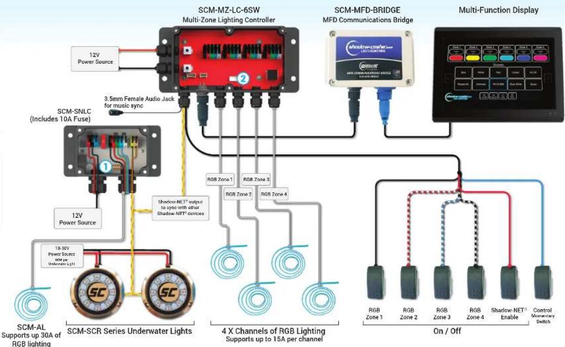
Standard Layout
SCM-MFD-LC-KIT & SCM-SNLC with 6 Switch Inputs, Shadow-NET® Lights & 5 Zones of RGB Lights

HOW TO OPERATE
RGB Switches enables RGB Zones 1-4.
Shadow-NET Switch enables all lights connected to Shadow-NET®.
Control Switch momentary push button to change color and control brightness.
MFD control will override all switches.
RECOMMENDED WIRE GAUGES
Scan the QR Code or click here to view our recommended wire gauge chart.

flowchart
graph TD
    A["12V Power Source"] --> B["SCM-MZ-LC-6SW Multi-Zone Lighting Controller"]
    C["3.5mm Female Audio Jack for music sync"] --> B
    D["12V Power Source"] --> E["SCM-SCR Series Underwater Lights"]
    F["10-30V Power Source 60μF per Underwater Light"] --> E
    G["RGB Zone 1"] --> H["4 X Channels of RGB Lighting Supports up to 15A per channel"]
    I["RGB Zone 2"] --> H
    J["RGB Zone 3"] --> H
    K["RGB Zone 4"] --> H
    L["RGB Zone 1"] --> M["On / Off"]
    N["RGB Zone 2"] --> M
    O["RGB Zone 3"] --> M
    P["RGB Zone 4"] --> M
    Q["Shadow-NET Enable"] --> M
    R["Control Monestary Switch"] --> M
    S["Multi-Function Display"] --> T["SCM-MFD-BRIDGE MFD Communications Bridge"]
    U["12V Power Source"] --> V["SCM-SNLC (Includes 10A Fuse)"]
    W["4 X Channels of RGB Lighting Supports up to 15A per channel"]
    X["On / Off"] --> Y["RGB Zone 1"]
    X --> Z["RGB Zone 2"]
    X --> AA["RGB Zone 3"]
    X --> AB["RGB Zone 4"]
    X --> AC["Shadow-NET Enable"]
① SCM-SNLC DIP SWITCH SETTINGS (from left to right counting up)
| 1 2 3 4 | ||||
| ↑ | Not Used | Color | Master(please turn a Switch) | RGB |
| ↓ | Not Used Blue/White only | on only RGBW | ||
② SCM-MZ-LC DIP SWITCH SETTINGS (from left to right counting up)
| 1 2 3 4 | ||||
| ↑ | Zone 1 RGB | Zone 2 RGB Zone 3 RGB Zone 4 RGB | ||
| ↓ | Zone 1 RGBW Zone 2 RGBW Zone 3 RGBW Zone 4 RGBW | |||
REVISED
March 5th 2021
Shadow-Caster® LED Lighting | 2060 Calumet St. | Clearwater, FL 33765
p: 1+727.474.2877 | e: info@shadow-caster.com | w: Shadow-Caster.com
Standard Layout
SCM-MFD-LC-KIT with 2 Switch Inputs, Shadow-NET® Lights & 4 Zones of RGB Lights

HOW TO OPERATE
RGB Switch enables RGB Zones 1-4.
Control Switch Press and hold for brightness. Press to start/stop color rotation.
Shadow-NET Lights all controlled via MFD.
MFD control will override all switches.
RECOMMENDED WIRE GAUGES
Scan the QR Code or click here to view our recommended wire gauge chart.


flowchart
graph TD
    A["12V Power Source"] --> B["SCM-MZ-LC-2SW Multi-Zone Lighting Controller"]
    C["3.5mm Female Audio Jack for music sync"] --> B
    D["Shadow-NET output to sync with other Shadow NET devices"] --> B
    E["4X Channels of RGB Lighting Supports up 15A per channel"] --> B
    F["RGB Zone 1-4 On/Off"] --> G["Control Momentary Switch"]
    H["Multi-Function Display"] --> I["Multi-Function Display"]
    J["10-30V Power Source"] --> K["SCM-SL-CC Spreader Light"]
    K --> L["SCM-DLX-CC Down Lights"]
    L --> M["SCR-24-CC Underwater Lights"]
    M --> N["4X Channels of RGB Lighting Supports up 15A per channel"]
    O["Shadow Cluster LED Lighting"] --> P["Multi-Function Display"]
    Q["RGB Zone 1-4 On/Off"] --> R["Control Momentary Switch"]

SCM-MZ-LC DIP SWITCH SETTINGS
(from left to right counting up)
| 1 | 2 | 3 | 4 | |
| ↑ | Zone 1 RGB | Zone 2 RGB | Zone 3 RGB | Zone 4 RGB |
| ↓ | Zone 1 RGBW | Zone 2 RGBW | Zone 3 RGBW | Zone 4 RGBW |
REVISED
March 5th 2021
Shadow-Caster® LED Lighting | 2060 Calumet St. | Clearwater, FL 33765
p: 1+727.474.2877 | e: info@shadow-caster.com | w: Shadow-Caster.com
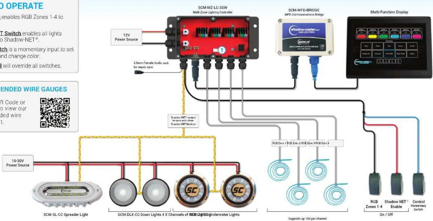
Standard Layout
SCM-MFD-LC-KIT with 3 Switch Inputs, Shadow-NET® Lights & 4 Zones of RGB Lights

HOW TO OPERATE
RGB Switch enables RGB Zones 1-4 to white color.
Shadow-NET Switch enables all lights connected to Shadow-NET ^® .
Control Switch is a momentary input to set brightness and change color.
MFD control will override all switches.
RECOMMENDED WIRE GAUGES
Scan the QR Code or click here to view our recommended wire gauge chart.

flowchart
graph TD
    A["Multi-Zone Lighting Controller"] -->|12V Power Source| B["10-30V Power Source"]
    A -->|3.5mm Female Audio Jack for music sync| C["Shadow NET+ output for audio with other Shadow NET Hostless"]
    A --> D["Multi-Function Display"]
    D --> E["RGB Zones 1-4 Enable On/Off"]
    D --> F["RGB Zone 1 RGB Zone 2 RGB Zone 3 RGB Zone 4"]
    A --> G["SCM-SL-CC Spreader Light"]
    A --> H["SCM-DLX-CC Down Lights 4 X Channels of SGB Light"]
    A --> I["SC"]
    A --> J["SC"]
    A --> K["Supports up 15A per channel"]

SCM-MZ-LC DIP SWITCH SETTINGS (from left to right counting up)
| 1 | 2 | 3 | 4 | |
| ↑ | Zone 1 RGB | Zone 2 RGB | Zone 3 RGB | Zone 4 RGB |
| ↓ | Zone 1 RGBW | Zone 2 RGBW | Zone 3 RGBW | Zone 4 RGBW |
REVISED
March 5th 2021
Shadow-Caster® LED Lighting | 2060 Calumet St. | Clearwater, FL 33765
p: 1+727.474.2877 | e: info@shadow-caster.com | w: Shadow-Caster.com
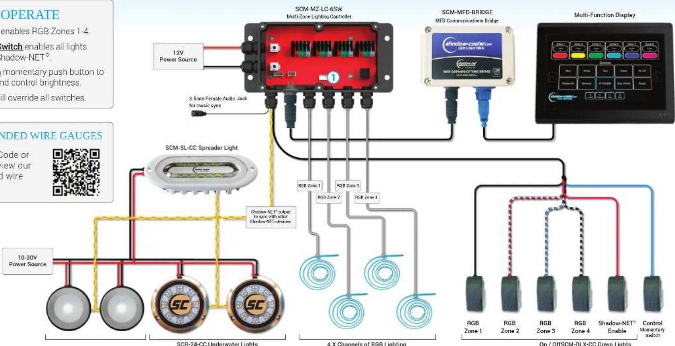
Standard Layout
SCM-MFD-LC-KIT with 6 Switch Inputs, Shadow-NET® Lights & 4 Zones of RGB Lights

HOW TO OPERATE
RGB Switches enables RGB Zones 1-4.
Shadow-NET Switch enables all lights connected to Shadow-NET ^® .
Control Switch momentary push button to change color and control brightness.
MFD control will override all switches.
RECOMMENDED WIRE GAUGES
Scan the QR Code or click here to view our recommended wire gauge chart.

flowchart
graph TD
    A["10-30V Power Source"] --> B["SCR-24-CC Underwater Lights"]
    C["12V Power Source"] --> D["Multi-Zone Lighting Controller"]
    E["3.5mm Female Audio Jack for music sync"] --> D
    F["RGB Zone 1"] --> G["4 X Channels of RGB Lighting"]
    H["RGB Zone 2"] --> G
    I["RGB Zone 3"] --> G
    J["RGB Zone 4"] --> G
    K["RGB Zone 1"] --> L["On / OffSCM-DLX-CC Down Lights"]
    M["RGB Zone 2"] --> L
    N["RGB Zone 3"] --> L
    O["RGB Zone 4"] --> L
    P["Shadow-NET Enable"] --> L
    Q["Control Momentary Switch"] --> L
    R["Multi-Function Display"] --> S["Multi-Function Display"]
    T["12V Power Source"] --> U["3.5mm Female Audio Jack for music sync"]
    V["4X Channels of RGB Lighting"] --> W["RGB Zone 1"]
    V --> X["RGB Zone 2"]
    Y["RGB Zone 3"] --> Z["RGB Zone 4"]
    AA["RGB Zone 4"] --> Z
    AB["RGB Zone 1"] --> AC["On / OffSCM-DLX-CC Down Lights"]

SCM-MZ-LC DIP SWITCH SETTINGS (from left to right counting up)
| 1 | 2 | 3 | 4 | |
| ↑ | Zone 1 RGB | Zone 2 RGB | Zone 3 RGB | Zone 4 RGB |
| ↓ | Zone 1 RGBW | Zone 2 RGBW | Zone 3 RGBW | Zone 4 RGBW |
REVISED
March 5th 2021
Shadow-Caster® LED Lighting | 2060 Calumet St. | Clearwater, FL 33765
p: 1+727.474.2877 | e: info@shadow-caster.com | w: Shadow-Caster.com
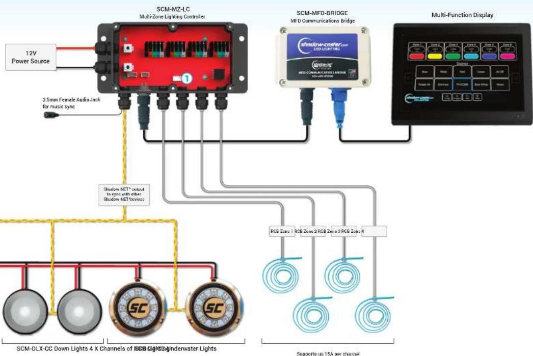
Standard Layout
SCM-MFD-LC-KIT with
Shadow-NET® Lights & 4 Zones of RGB Lights

ndow-caster
LED LIGHTING
HOW TO OPERATE
All configuration and control of system will be done through the MFD user interface.
RECOMMENDED WIRE GAUGES
Scan the QR Code or click here to view our recommended wire gauge chart.

flowchart
graph TD
    A["12V Power Source"] --> B["SCM-MZ-LC Multi-Zone Lighting Controller"]
    B --> C["3.5mm Female Audio Jack for music sync"]
    B --> D["Shadow NET* output to sync with other Shadow NET Service"]
    D --> E["SCM-DLX-CC Down Lights 4 X Channels of SGB Light/Indenwater Lights"]
    D --> F["SC"]
    D --> G["SC"]
    H["SCM-MFD-BRIDGE MFD Communications Bridge"] --> I["Shadow create LED Lighting"]
    I --> J["Multi-Function Display"]
    J --> K["RGB Zones 1 RGB Zone 2 RGB Zone 3 RGB Zone 4"]
    K --> L["Supports up 15A per channel"]

SCM-MZ-LC DIP SWITCH SETTINGS
(from left to right counting up)
| 1 | 2 | 3 | 4 | |
| ↑ | Zone 1 RGB | Zone 2 RGB | Zone 3 RGB | Zone 4 RGB |
| ↓ | Zone 1 RGBW | Zone 2 RGBW | Zone 3 RGBW | Zone 4 RGBW |
REVISED
March 5th 2021
Shadow-Caster® LED Lighting | 2060 Calumet St. | Clearwater, FL 33765
p: 1+727.474.2877 | e: info@shadow-caster.com | w: Shadow-Caster.com