
SVE4BW3 - Hot plate SVAN - Free user manual and instructions
Find the device manual for free SVE4BW3 SVAN in PDF.

| Brand | SVAN |
| Model | SVE4BW3 |
| Product Type | Built-in gas hob |
| Number of Burners | 4 (Auxiliary, Semi-rapid, Rapid, Triple ring) |
| Burner Power (Auxiliary) | 0.90 kW |
| Burner Power (Semi-rapid) | 1.88 kW |
| Burner Power (Rapid) | 2.40 kW |
| Burner Power (Triple ring) | 3.40 kW |
| Gas Types Supported | Natural gas (G20, G25, G25.1, G27, G2.350) and LPG (G30 butane/propane) |
| Supply Pressure (Natural gas G20) | 20 mbar |
| Supply Pressure (LPG G30) | 30-50 mbar |
| Ignition | Automatic via knob press and turn |
| Safety Features | Thermocouple automatic shut-off, automatic safety valves |
| Electrical Connection | 230 V~, 3 x 0.75 mm² H05V2V2-F cable |
| Installation Clearance | At least 30 mm clearance below hob, 50 mm from side walls, 650 mm above to hood/cabinet |
| Pan Diameter Range (Auxiliary) | 8 – 14 cm |
| Pan Diameter Range (Semi-rapid) | 14 – 20 cm |
| Pan Diameter Range (Rapid) | 20 – 28 cm |
| Pan Diameter Range (Triple ring) | Above 26 cm |
| Cleaning Recommendations | Enamel parts: soapy water; burners/grids: remove and clean; avoid acidic/chlorine products |
| Maintenance | Gas tap lubrication by qualified technician only |
| Spare Parts Availability | Injectors and other parts from Service Centre |
Frequently Asked Questions - SVE4BW3 SVAN
User questions about SVE4BW3 SVAN
0 question about this device. Answer the ones you know or ask your own.
Ask a new question about this device
Download the instructions for your Hot plate in PDF format for free! Find your manual SVE4BW3 - SVAN and take your electronic device back in hand. On this page are published all the documents necessary for the use of your device. SVE4BW3 by SVAN.
USER MANUAL SVE4BW3 SVAN
Igniting the burners
In these models the knob controls both ignition and the safety device. Proceed as follows to ignite the burners:
1) Turn the chosen knob.
2) Keep the knob strongly pressed in for 3/4 seconds to permit the spark to light the gas that exits from the flametamer and to permit the thermocouple to heat up.
3) Release the knob after about 3/4 seconds and adjust the flame as desired, rotating
the knob anti-clockwise. Repeat points 1 and 2 if the flame does not remain on.
Using the burners
For greater efficiency and less gas consumption use pots and pans with the right diameters for the burners. Avoid having flames extending out from underneath the pans (refer to the table).
| Table of recommended pans | |
| Burner ∅ Pan diameter in cm | |
| Auxiliary | from dia. 8 to dia. 14 |
| Semi rapid | from dia. 14 to dia. 20 |
| Rapid | from dia. 20 to dia. 28 |
| Triple ring | Above dia. 26 |
Automatic safety valves
This safety device automatically closes the gas valve if the inconvenience caused by failure to comply with this rule.
CLEANING AND MAINTENANCE GENERAL
Cleaning and maintenance should be carried out with the appliance cold especially when cleaning the enamelled parts. Avoid leaving alkaline or acid substances(lemon juice, vinegar
etc.)on the surfaces.
Avoid using acid or chlorine-based cleaning products.
ENAMELLED PARTS
All of the enamelled parts must be washed only with a sponge and soapy water or with non-abrasive products.
BURNERS AND GRIDS
These parts can be removed and cleaned with appropriate products.
After cleaning, the burners and their flame distributors must be well dried and correctly replaced.
It is very important to check that the burner flame distributor F and the cap C has been correctly positioned (fig. 6) -failure to do so can cause serious problems.
Check that the electrode S is always clean to ensure trouble-free sparking.
Check that the probe T is always clean to ensure correct operation of the safety valves (for models with safety device).
Both the probe and ignition plug must be very carefully cleaned

GAS TAPS
Periodic lubrication of the gas taps must be carried out by specialist personnel only.
In the event of operating faults in the gas taps, call the Service Department.
GENERAL ADVICE
√When the appliance is not being used, it is advisable to keep the gas tap closed.
√If the gas tap becomes stiff, it is necessary to dismount it accurately, clean it with gasoline and spread a bit of special grease resistant to high temperatures on it. This operation must be executed by a qualified technician.
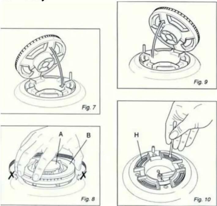
TRIPLE RING BURNER
The triple ring burner must be correctly positioned(seen fig.7);the burner rib must be enter in their logement as shown by the arrow.
The burner correctly positioned must not rotate (fig.8).
Then position the cap A and the ring B(fig.8).
CLEANING THE TRLPLE RING BURNER
Pay special attention to this burner: the four holes around the outside of the crown must always be kept clean.
When cleaning, remove the flame divider (fig.9) and use a cotton bud, toothbrush, or some other item to clean out any incrustations or dirt from the four holes marked. "H" (fig.10).
This procedure is necessary to ensure the burner functions correctly.
Advice for the Installer
IMPORTANT
√The appliance should be installed, regulated and adapted to function with other types of gas by a QUALIFIED INSTALLATION TECHNICIAN.
Failure to comply with this condition will render the guarantee invalid.
√The appliance must be installed in compliance with regulations in force.
√Always unplug the appliance before carrying out any maintenance operations or repairs.
√The appliance must be housed in heat resistant units.
√The walls of the units must not be higher than work top and must be capable of resisting temperatures of 75 above °C temperature.
√Do not install the appliance near inflammable materials (eg. curtains).
INSTALLATION
Foreword:
These tops are designed to be embedded into kitchen fixtures measuring 600 mm in depth.
In order to install the cooker top into the kitchen fixture, a hole with the dimensions shown on the cutting size board has to be made, keeping in consideration the following:
√within the fixture, between the bottom side of the cooker top and the upper surface of any other appliance or internal shelf there must be a clearance of at least 30 mm;
√the cooker top must be kept no less than 100 mm away from any side wall;
√the hob must be installed at least 50 mm from the wall.
√there must be a distance of at least 650 mm between the hob and any wall cupboard or extractor hood positioned immediately above.
√It is essential to install a heat baffle between the bottom of the hob and the underlying unit.

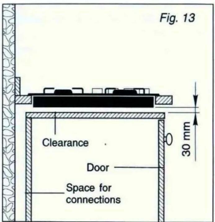
INSTALLATION IN KITCHEN CABINET WITH DOOR (fig.13)
The fixture has to be made according to specific requirements in order to prevent the gas burners from going out, even when the flame is turned down to minimum, due to pressure changes while opening or closing the cupboard doors.
It is recommended that a 30 mm clearance be left between the cooker top and the fixture surface (fig.13).
SETTLING THE HOB FOR INSTALLATION
Every cooker top is provided with a set of tabs for fitting to the unit with thickness from 3 to 4 cm and a seal with adhesive on one side.
-Remove burners and grids.
-Turn the cooker top over and rest the glass side on a cloth.
-Apply the self-adhesive seal "G" as illustrated in fig.14.
-Slot the cooker top into the unit and position.
-Position the cooker top in the recess and secure by means of the brackets as shown in fig.15(for 3 or 4 cm thick work top).


INSTALLATION ROOM
The room where the gas appliance is to be installer must have a natural flow of air so that the gas can burn.
The flow of air must come directly from one or more openings made in the out-side walls with a free area of at least 100cm^2 . If the appliance does not have a no-flame safety device this opening must have an area of at least 200cm^2 .
The openings should be near the floor and preferably on the side opposite the exhaust for combustion products and must be so made that they cannot be blocked from either the outside or the outside.
When these openings cannot be made the necessary air can come from an adjacent room which is ventilated as required, as long as it is not a bedroom or a dangerous area.
In this case the kitchen door must allow the passage of the air.
DISCHARGING PRODUCTS OF COMBUSTION
Extractor hoods connected directly to the outside must be provided, to allow the products of combustion of the gas appliance to be discharged (fig.16).
If this is not possible, an electric fan may be used, attached to the external wall or the window; the fan should have a capacity to circulate air at an hourly rate of 3-5 times the total volume of the kichen (fig.17).
The fan can only be installed if the room has suitable vents to allow air to enter, as described under the hesding “Installation room”

GAS SECTION
TYPES OF GASES
The gases normally used may be grouped, in view of their features, in three families:
-L.P.G.(in cylinders) G30
-NATURAL GAS(methane) G 20
-CITY GAS G110
INSTALLATION
The appliance is predisposed and adjusted to operate with the gas indicated on the specifications plate applied onto the appliance.
If the appliance must be operated with a gas different than that indicated on the plate, it is necessary to execute the following operations:
-gas connection
-replacement of the injectors
-regulating of the minimum
GAS CONNECTION
The connection must be executed by qualified technician according to the relevant standard.
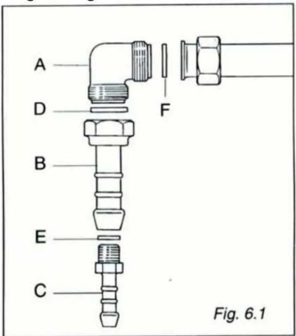
The fitting (fig.6.1) is made up of:
√1 elbow fitting“A”
√1 adapter "B" for natural or city gas
√gaskets “D”, “E” and “F”
The hob must be installed in a room with adequate ventilation(see page 13).
Gas connection for:
Natural gas (G20) or city gas (G110)
√Remove the adapter“C”using two spanners.
√Connect the cooking hob to the gas net by a suitable rubber tube(inside diameter 13 mm).
L.P.G.(in cylinders)G30
√Fit up the adapter “C” to the adapter “B” interposing gasket“E”. Tighten using two spanners.
√Connect the cooking hob to the cylinder pressure regulator by a suitable rubber tube (inside diameter 8 mm).
Make sure the tube is snugly fit at both ends and use a standard tube clamp (not supplied) to fasten it.
Orientation of the elbow
The appliance is supplied with a gas connection oriented towards the centre of the cooking hob. The connection to the gas supply must be effected only from this side or in vertical position by turning the elbow downwards. To turn the elbow, follow these operations:
√loosen the nut
√turn the elbow
√lock the nut
√make sure that there are no leakages by a soapy solution
IMPORTANT:
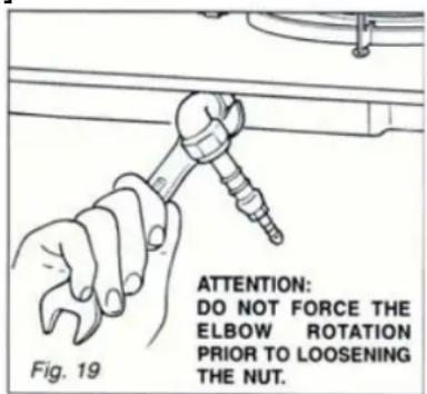
√Never attempt to turn the elbow “A” without having first slackened off the relative lock nipple.
√The seals“D-E-F”(fig.18) are the elements that guarantees the seal in the gas connection.
Is is recommended that they be replaced whenever they show even the slightest deformation or imperfection.
√After connecting to the mains, check that the couplings are correctly sealed, using soapy solution, but never a naked flame.
√The connection with rigid metal pipes should not cause stresses to the bob ramp.
√If the rubber tube is used for the gas connection:
-Make sure the tube is snugluy fit at both ends and use a standard tube clamp (not supplied) to fasten it.
-The rubber tube must be as short as possible, without contractions or kinks.
-The rubber tube must never be at any point in its length in contact with the "hot" parts.
-From time to time check to make sure that the rubber is in perfect condition and
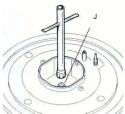
OPERATIONS TO BE PERFORMED WHEN SUBSTITUTING THE INJECTORS
If the injectors are not supplied they can be obtained from the “Service Centre”.
√Remove the gratings and the burner covers;
√Using a wrench, substitute the nozzle injectors. “J”(Fig.20) with those most suitable for the kind of gas for which it is to be used (see Injector table).
The burners are conceived in such a way so as not to require the regulation of the primary air.
Fig. 20
natural_image
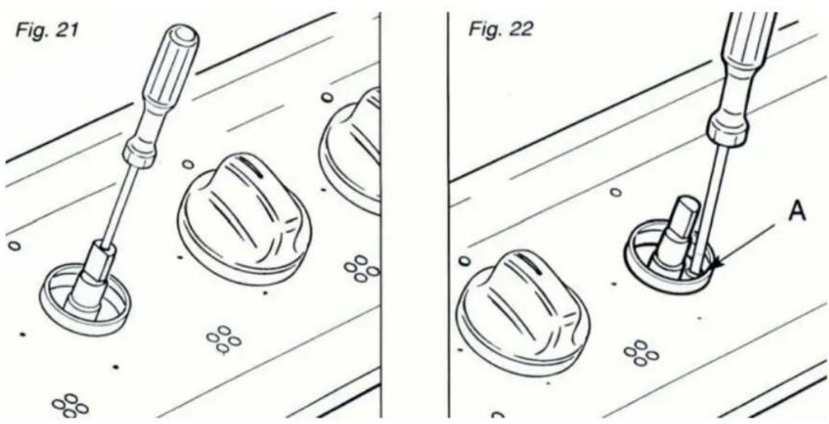
Technical line drawing of a mechanical component with concentric circles and a central shaft (no text or symbols)REGULATING THE BURNER MINIMUM SETTING
When switching from one type of gas to another, the minimum flow rate must also be correct: the flame should not go out even when passing suddenly from maximum to minimum flame. To regulate the flame follow the instructions below:
√Light the burner
√Set the cock valve to minimum
On gas valves provided with adjustment screw in the centre of the shaft(fig.21)
√Using a screwdriver with max.diameter 3 mm,turn the screw inside the tap until the correct setting is obtained.
On gas valves provided with adjustmet screw on the valve body(fig.22):
√turn the screw "A" to the correct setting with a screwdriver.
Normally for G30 gas, fully tighten the adjustment screw.
LUBRICATION OF THE GAS TAPS
If the gas tap becomes stiff, it is necessary to dismount it accurately clean it with gasoline and spread a bit of special grease resistant to high temperatures on it.
The operations must be executed by a qualified technician.
ELECTRICAL SECTION
IMPORTANT:
Installation has to be carried out according to instructions provided by the manufacturer.
Incorrect installation might cause harm and damage to people, animals or objects, for which the manufacturer accepts no responsibility.
DETAILS
√Connection to the electric power supply must be carried out by a qualified technician and following the appropriate safety regulations;
√Before carrying out the connection to the power supply, the voltage rating of the appliance(stamped on the appliance identification plate) must be checked for correspondence to the available mains supply voltage, and the mains electric wiring should be capable of handling the hob's power rating (also indicated on the identification plate);
√The power point must be connected to a suitable earth wiring, in conformity to current safety regulations.
√If the appliance is supplied without plug, fit a standard plug which is suitable for the power consumed by the appliance.
√The colours of the wires in the hob power cable may not correspond with the colours marked on the terminals of your electrical plug. The plug should in any case be wired as follows:
—connect the green/yellow wire to the terminal marked with the letter E or the earth symbol or coloured green/yellow;
—connect the blue wire to the terminal marked with the letter N or coloured black;
—connect the brown wire to the terminal marked with the letter L or coloured red.
√It is possible to connect the appliance directly to the mains supply by means of a heavy duty switch with 3 mm minimum distance between the contacts.
√The power supply cord must not touch against any hot surfaces and must be placed so that its temperature does not exceed 75 at any point along its length. ^ C
√After having installed the appliance, the power switch or power plug must always be in a accessible position.
N.B For connections to the mains power supply, never use adapters, reductions or multiple power points as these may overheat and catch fire.
In the event that installation should require modifications to the
mains supply wiring system or if the power plug is not suitable for the type of power point available, it is recommended that a qualified technician be called to carry out substitution.
The technician will also have to verify that the cross-section of the electric cables on the power point match the appliance's power rating.
REPLACING THE POWER SUPPLY CABLE
Use the same type of power supply cable.
This cable must be connected to the terminal block following the diagram in fig.23
SECTION OF THE SUPPLY CABLES Type“H05V2V2-F” resistance to temperatures of 90°C
230V\~
3x0, 75mm²
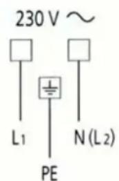
Fig. 23
Connection to a good earth wiring system is absolutely essential.
The manufacturer accepts no responsibility for any inconvenience caused by failure to comply with this rule.
Descriptions and illustrations in this booklet are given as simply indicative.
The manufacturer reserves the right, considering the characteristics of the models described here, at any time and without notice, to make eventual necessary modifications for their construction or for commercial needs.
Burners and Nozzle Specifications
| Table1 | G20 | G25 | G25.1 | G27 | G2.350 | G30 | ||||||||
| Burner | Thermal power (kW) | Nozzle 1/100 (mm) | Thermal power kW | Nozzle 1/100 (mm) | Thermal power kW | Nozzle 1/100 (mm) | Thermal power kW | Nozzle 1/100 (mm) | Thermal power kW | Nozzle 1/100 (mm) | Thermal power kW | Nozzle 1/100 (mm) | Nozzle 1/100 (mm) | Nozzle 1/100 (mm) |
| Auxiliary (Small) (A) | 0.90 | 69 | 0.90 | 69 | 0 | 90 | 69 | 0.90 | 75 | 0.90 | 96 | 0.90 | 50 | 4 |
| Semi rapid (Medium) | 1.88 | 97 | 1.88 | 97 | 1 | 88 | 97 | 1.88 | 106 | 1.88 | 131 | 1.88 | 68 | |
| Rapid (R) | 2.40 | 110 | 2.40 | 110 | 2 | 40 | 110 | 2.40 | 121 | 2.40 | 147 | 2.40 | 78 | |
| Triple Ring (TR) | 3.40 | 123 | 3.40 | 123 | 3 | 40 | 123 | 3.40 | 145 | 3.40 | 180 | 3.40 | 91 | 86 |
| Supply pressure s | 20mbar | 25mbar | 25mbar | 20mbar | 13mbar | 30 mbar | 37 mbar | 50 mbar | ||||||
At 15°C and 1013 mbar-dry gas
| P.C.I.G20 | 37.78 MJ/m ^3 | P.C.I.G25.1 | 32.51 MJ/m ^3 |
| P.C.I.G25 | 32.49 MJ/m ^3 | P.C.I.G27 | 30.98 MJ/m ^3 |
| P.C.I.G2.350 | 27.20MJ/ m ^3 | P.C.I.G30 | 49.47MJ/Kg |
TABLE N°2: Adapting to different types of gas
APPLIANCE CATEGORY: I_2HS , II_2H3+ , II_2E3B/P , II_2HS3B/P30,50 , II_2ElwLs3B/P
| Burner | Type of Gas | Pressure | Nozzle diameter | Nominal Charge | Reduced Charge | ||||
| mbar | 1/100mm | g/h | l/h | kW | kcal/h | kW | kcal/h | ||
| Auxiliary | Natural G20 | 20 | 69 | — | 85.7 | 0.90 | 774 | 0.40 | 344 |
| Natural G25 | 25 | 69 | — | 99.7 | 0.90 | 774 | 0.40 | 344 | |
| Natural G25.1 | 25 | 69 | — | 99.6 | 0.90 | 774 | 0.40 | 344 | |
| Natural G27 | 20 | 75 | — | 104.5 | 0.90 | 774 | 0.40 | 344 | |
| Natural G2.350 | 13 | 96 | — | 119 | 0.90 | 774 | 0.40 | 344 | |
| Butane G30 | 30 | 50 | 65 | — | 0.90 | 774 | 0.40 | 344 | |
| 37 | 44 | 65 | — | 0.90 | 774 | 0.40 | 344 | ||
| 50 | 43 | 65 | — | 0.90 | 774 | 0.40 | 344 | |||
| Semi-rapid | Natural G20 | 20 | 97 | — | 179 | 1.88 | 1617 | 0.60 | ||
| Natural G25 | 25 | 97 | — | 208.3 | 1.88 | 1617 | 0.60 | |||
| Natural G25.1 | 25 | 97 | — | 208.1 | 1.88 | 1617 | 0.60 | |||
| Natural G27 | 20 | 106 | — | 218.5 | 1.88 | 1617 | 0.60 | |||
| Natural G2.350 | 13 | 131 | — | 248.8 | 1.88 | 1617 | 0.60 | |||
| Butane G30 | 30 | 68 | 136 | — | 1.88 | 1617 | 0.60 | |||
| 37 | 64 | 136 | — | 1.88 | 1617 | 0.60 | ||||
| 50 | 60 | 136 | — | 1.88 | 1617 | 0.60 | ||||
| Rapid | Natural G20 | 20 | 110 | — | 228 | 2.4 | 2064 | 0.90 | 774 | |
| Natural G25 | 25 | 110 | — | 265.9 | 2.4 | 2064 | 0.90 | 774 | ||
| Natural G25.1 | 25 | 110 | — | 265.7 | 2.4 | 2064 | 0.90 | 774 | ||
| Natural G27 | 20 | 121 | — | 278.8 | 2.4 | 2064 | 0.90 | 77 | ||
| Natural G2.350 | 13 | 147 | — | 317.6 | 2.4 | 2064 | 0.90 | 77 | ||
| Butane G30 | 30 | 78 | 174 | — | 2.4 | 2064 | 0.90 | |||
| 37 | 72 | 174 | — | 2.4 | 2064 | 0.90 | ||||
| 50 | 68 | 174 | — | 2.4 | 2064 | 0.90 | ||||
| Triple-ring | Natural G20 | 20 | 123 | — | 323 | 3.4 | 2924 | 1.50 | 1290 | |
| Natural G25 | 25 | 123 | — | 376.7 | 3.4 | 2924 | 1.50 | 12 | ||
| Natural G25.1 | 25 | 123 | — | 376.5 | 3.4 | 2924 | 1.50 | 12 | ||
| Natural G27 | 20 | 145 | — | 395 | 3.4 | 2924 | 1.50 | 1290 | ||
| Natural G2.350 | 13 | 180 | — | 450 | 3.4 | 2924 | 1.50 | 1290 | ||
| Butane G30 | 30 | 91 | 247 | — | 3.4 | 2924 | 1.50 | |||
| 37 | 86 | 247 | — | 3.4 | 2924 | 1.50 | ||||
| 50 | 83 | 247 | — | 3.4 | 2924 | 1.50 | ||||


- Igniting the burners
- Using the burners
- Automatic safety valves
- CLEANING AND MAINTENANCE GENERAL
- ENAMELLED PARTS
- BURNERS AND GRIDS
- GAS TAPS
- GENERAL ADVICE
- TRIPLE RING BURNER
- CLEANING THE TRLPLE RING BURNER
- Advice for the Installer
- IMPORTANT
- INSTALLATION
- Foreword:
- INSTALLATION IN KITCHEN CABINET WITH DOOR (fig.13)
- SETTLING THE HOB FOR INSTALLATION
- INSTALLATION ROOM
- DISCHARGING PRODUCTS OF COMBUSTION
- GAS SECTION
- TYPES OF GASES
- GAS CONNECTION
- Gas connection for:
- Natural gas (G20) or city gas (G110)
- L.P.G.(in cylinders)G30
- Orientation of the elbow
- OPERATIONS TO BE PERFORMED WHEN SUBSTITUTING THE INJECTORS
- If the injectors are not supplied they can be obtained from the “Service Centre”.
- REGULATING THE BURNER MINIMUM SETTING
- On gas valves provided with adjustment screw in the centre of the shaft(fig.21)
- On gas valves provided with adjustmet screw on the valve body(fig.22):
- LUBRICATION OF THE GAS TAPS
- ELECTRICAL SECTION
- IMPORTANT:
- DETAILS
- N.B For connections to the mains power supply, never use adapters, reductions or multiple power points as these may overheat and catch fire.
- REPLACING THE POWER SUPPLY CABLE
- SECTION OF THE SUPPLY CABLES Type“H05V2V2-F” resistance to temperatures of 90°C
- Descriptions and illustrations in this booklet are given as simply indicative.
Brand : SVAN
Model : SVE4BW3
Category : Hot plate