SVCC9070N - Coffee maker SVAN - Free user manual and instructions
Find the device manual for free SVCC9070N SVAN in PDF.

User questions about SVCC9070N SVAN
0 question about this device. Answer the ones you know or ask your own.
Ask a new question about this device
Download the instructions for your Coffee maker in PDF format for free! Find your manual SVCC9070N - SVAN and take your electronic device back in hand. On this page are published all the documents necessary for the use of your device. SVCC9070N by SVAN.
USER MANUAL SVCC9070N SVAN
HOOD USER GUIDE ENGLISH
natural_image
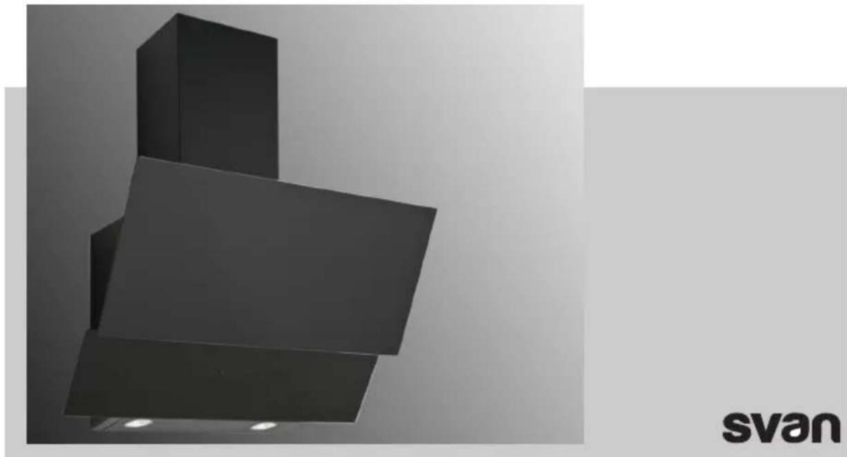
Modern black industrial chimney with a reflective roof, displayed against a plain wall (no text or symbols visible)CAMPANA INCLINADA 90CM
CRISTAL BLANCO_SVCC9070
CAMPANA INCLINADA 90CM
CRISTAL NEGRO_SVCC9070N
Read this manual prior to performing any task!
This device is designed exclusively for domestic use
Table of contents
1 Technical Drawing.... 4
2 WARNING AND SAFETY PRECAUTIONS.... 5
2.1 LETHAL RISK, DANGER OF POISONING....7
3 USAGE WITH AND WITHOUT CARBON FILTER.... 11
4 Carbon Filter Replacement.... 12
5 CLEANING AND PREVENTIVE MAINTENANCE.... 13
5.1 ALUMINIUM FILTER CLEANING.... 13
5.2 Washing in Dishwasher.... 14
5.3 Hand Wash.... 14
6 APPLIANCE POSITION.... 15
7 CLEANING AND PREVENTIVE MAINTENANCE.... 16
7.1 Installation and Unpacking of the Appliance.... 16
7.2 Recommendations for Energy Saving.... 16
8 CONTENT OF PACKAGE.... 17
9 OVERVIEW OF hood.... 18
10 ASSEMBLY OF PRODUCT.... 19
10.1 Installation Diagram and Components.... 19
11 AIR EXIT INSTALLATION.... 21
12 ASSEMBLY OF SHEET METAL FLUES.... 22
13 USE OF PRODUCT.... 23
13.1 3 Spd Touch Product Usage.... 23
13.2 Using Push Button Product.... 24
14 REPLACING THE LAMPS.... 25
14.1 Halogen Lamp Replacement.... 25
14.2 Plug Lamp Replacement.... 25
15 AUTHORIZED SERVICE.... 27
16 TECHNICAL TABLE 29
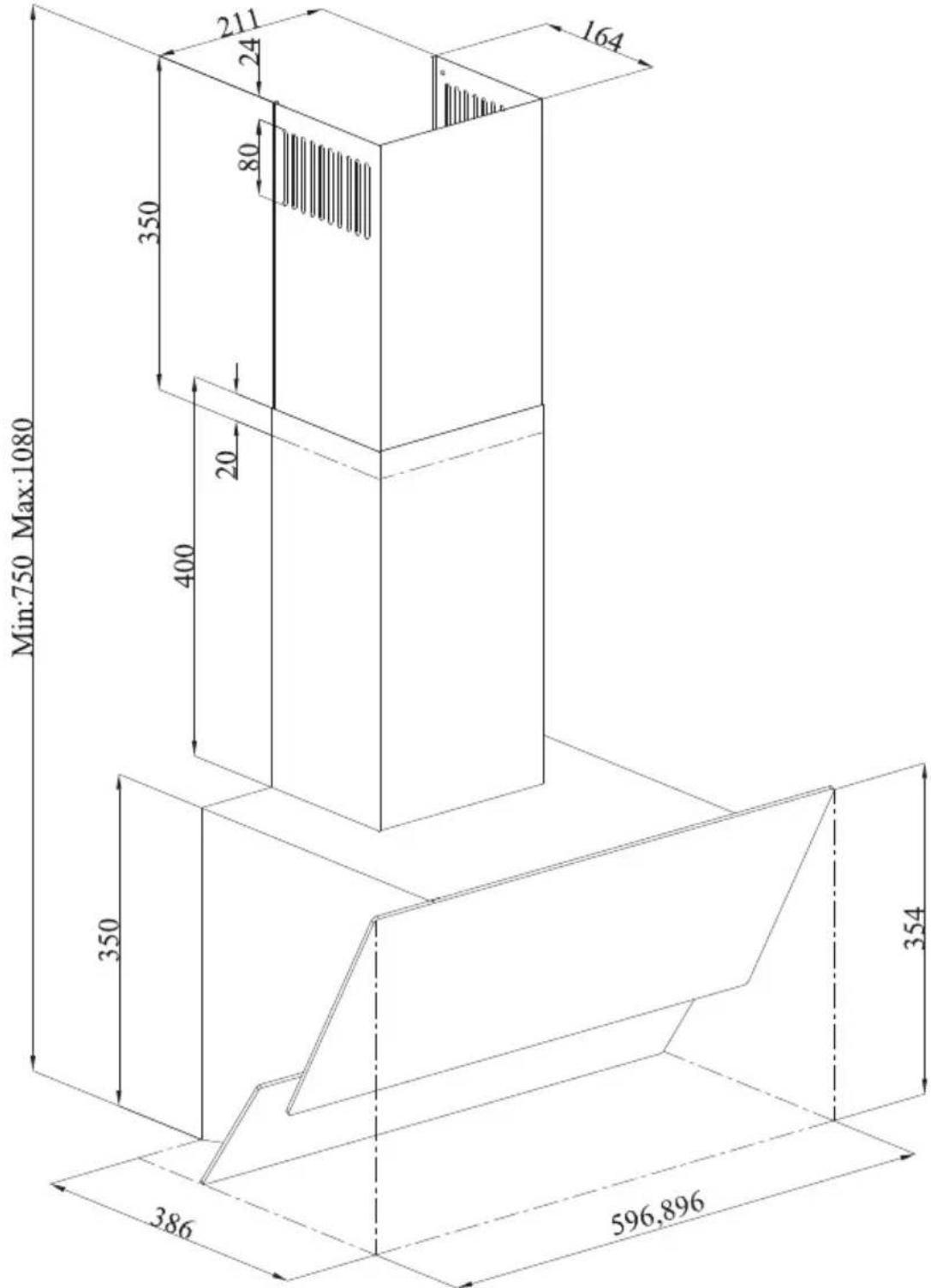
1 Technical Drawing
other
| Dimension | Value | | --------- | ----- | | Width | 350 | | Height | 386 | | Base | 596.896 | | Width | 350 | | Height | 400 | | Width | 211 | | Height | 24 | | Base | 20 | | Height | 80 | | Width | 164 | | Height | 350 |Fig. 1: 3420 DIMENSIONED TECHNICAL DRAWING
2 WARNING AND SAFETY PRECAUTIONS
WARNING AND SAFETY PRECAUTIONS
This appliance can be used by children of 8 years and older, people with physical, sensory or mental capability deficiency or people with lack of experience or knowledge; as long as they are provided supervision or instructions for the safe use of the appliance and they comprehend the dangers.
Children should not tamper with the appliance. Cleaning and user maintenance operations must not be performed by children unless supervised.
This product is designed for home use.
■ Usage voltage of your product is 220-240 Volt\~50-60 Hz.
■ Power cord of your product is fitted with a grounded plug. This cord must be plugged into a grounded outlet.
The whole electrical wiring must be installed by a qualified electrician.
■ Installation by unauthorized persons could lead to poor operation performance, damage to the product, and accidents.
- Feeder cable of the appliance mustn't be exposed to jamming or crashing during assembly. Feeder cable mustn't be placed near the cooker. In such cases, it might melt down and lead to fire.
- Do not plug in the appliance before the installation.
■ Make sure that the installation place allows the user to easily unplug the power cable in case of any danger.
Do not touch your product's lamps when they work for a long time. The lamps may burn your hand as they will be hot.
Kitchen hoods are manufactured for household use in normal home cooking. There is a risk of malfunction in other types of use, and the product guarantee will be void.
■ Comply with the rules and instructions regarding discharge of outgoing air, stipulated by the relevant authorities. (This warning does not apply to uses without flue.)
■ Flammable foods must not be cooked under the appliance.
- Start your product after you place pot, pan etc. on the stoves. Otherwise, high temperature may cause same parts of your products to deform.
■ Turn off the cooker's burner before taking the saucepan, pan, etc. off the cooker.
- Do not leave boiling oil on the stove. Pots that contain boiling oil may catch fire by itself.
■ Since oils could catch fire when you cook fried foods in particular, be careful about your curtains and tablecloths.
■ Ensure timely replacement of the filters. Filters not replaced in a timely manner pose risk of fire due to accumulated grease deposits on them.
- Do not use non-fire-resistant filtering materials instead of the filter.
- Do not operate your product without filter, and do not remove the filters when the product is in operation.
In case of any fire, de-energize the hood and any other cooking devices. (Plug off the appliance or turn off the main switch.)
If your product's periodic cleaning is not made in a timely manner, it could pose risk of fire.
■ De-energize the appliance before any maintenance operations. (Plug off the appliance or turn off the main switch.)
When electric cooker hood and devices fed with energies other than electricity operate simultaneously, the negative pressure in the room must not exceed 4 Pa (4 X 10 bar).
Gas or fuel oil burning appliances, such as room heaters, which share the same environment with your product, must be fully insulated from the exhaust of this product or they must be hermetical.
When you make a flue connection for your product, use pipes with a diameter of 150mm or 120 mm. The length of the duct connection as well as the number of elbows must be as minimum as possible.
■ Children must not play with the appliance.
For your safety, use "MAX 6 A" fuse in the hood system.
■ Since the packing materials could be dangerous, keep them away from children.
If the feeder cable is damaged, it must be replaced by its manufacturer or its authorized technical service or any other personnel qualified at the same level, in order to avoid any dangerous situation.
In case of any deflagration, de-energize the cooker hood and cooking appliances, and cover the flame. Never use water to extinguish the fire.
- When cooking appliances are in operation, their accessible parts could be hot.
This appliance is not intended to be used by people with physical, sensory and mental disabilities (including children) or those who have not adequate experience and knowledge regarding its use, unless they are under the supervision of a person responsible for the safety of the appliance.
■ After the installation of the hood, the minimum distance must be 65 cm between the product and any electric cooker; and 75 cm between it and any gas ranges or cookers burning other fuels.
■ Output of the hood must not be connected to air ducts, where there exist another smokes.
You must be careful when using the appliance spontaneously with other appliances (e.g. gas, diesel fuels, coal, wood, etc. burning heaters, shower heaters), which use the same air in the same environment. Attention must be paid when using them simultaneously. It is because the hood could adversely affect the combustion, by discharging the ambient air.
This warning does not apply to uses without flue.
When electric cooker hood is used simultaneously with devices that use gas or other fuels, there must be sufficient ventilation in the room (might not apply to devices that discharges the air back into the room).
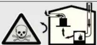
2.1 LETHAL RISK, DANGER OF POI- SONING

DANGER
Warning - Choking Hazard The packaging materials are dangerous for children. Never allow children to play with packaging materials.

DANGER
Warning - Death Hazard There are life-threatening danger and poisoning danger due to reabsorbed combustion gases. During the air discharge outlet use, unless sufficient air supply is provided, do not use the appliance simultaneously with devices that discharge toxic gases through flue such as ventilated, gas, oil, wood or coal burning heaters, shower heaters, water heaters, etc. Fig. 2
text_image
Safety warning symbol showing a skull and explosion next to an industrial smokestack with cooling fansFig. 2: Poisoning Danger
Ventilated goods (e.g. gas, oil, wood or coal burning heaters, shower heaters, water heaters) take combustion air from the installation location, and discharge the waste gas through a waste gas system (e.g. flue). When the cooker hood is active, it absorbs air from the kitchen and neighbouring rooms. If adequate air entry is not provided, vacuum emerges. In such a case, the toxic gases are absorbed from the flue and waste gas channel, and are taken into to door again. Fig. 2
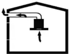
Therefore, adequate fresh air ingress must always be ensured. Fig. 3

natural_image
Simple line drawing of a house with airflow indicators and a checkmark (no text or symbols)Fig. 3

WARNING
Fire danger!
- The oil residue in the oil filter may catch fire.Clean the oil filter at least once every 3 months.Never operate the device without the oil filter.
- The oil residue in the oil filter may catch fire. Never work with open flame (ex. flambe) near the device. The apparatus is allowed to be installed near a solid fuel (e.g. wood or coal) heater only if it has a non-removable cover. No sparks should be scattered.
- Hot oils and fats catch fire easily. Hot oils and fats should never be left unattended. Never try to put out the fire with water. Turn off the cooker. Kill the flames carefully using a cover, fire blanket or a similar material.
- Gas operated cookers that do not have a cooking pot on create high heat during operation. A ventilation device placed over the cookers can be damaged or burned for this reason. Operate gas cookers only when there is a cooking pot on them.
- Operating multiple gas cookers simultaneously creates high heat. A ventilation device placed over the cookers can be damaged or burned for this reason. Never operate two gas cookers longer than 15 minutes on high flame setting. A large burner over 5kW (Wok) has the power of two gas burners.

WARNING
Electrocution hazard!
- A malfunctioning device may cause electric shock. Never turn on a malfunctioning device. Pull the power plug and switch off the circuit breaker. Call customer service.
- Unsuitable repairs pose hazards. Repairs and replacement of damaged power cords must be performed only by a customer services technician trained by us. If the device is malfunctioning pull the power plug and switch off the circuit breaker. Call customer service.
- Water leaking into the device may cause electric shock. High pressure or steam cleaners must not be used.

DANGER
Danger of physical injury!
– During the installation, there is a danger of physical injury due to the sharp edges. Use protective gloves throughout the installation process of the appliance.
- Due to risk of dropping the appliance, assembly of all safety bolts and covers must be performed as specified in the user manual.
- Objects placed on the appliance may fall over. Do not place any objects on the device.
- LED lights are very bright and may damage eyes (Risk group 1). You must not look directly at running LED lights for longer than 100 seconds.
WARNING
Risk of burn, risk of electric shock!
- Allow the appliance to cool before cleaning or maintenance process. Switch off the fuse or pull out the mains plug from the socket.
- There is risk of damage due to ingress of moisture in the electronics. Do not clean the control components with a wet cloth.
- The surface could be damaged due to a wrong cleaning process. Clean stainless steel surfaces only in their brushing direction. Do not use a stainless steel cleaner for the control elements.
- The surface could be damaged due to aggressive and abrasive cleaning agents. Never use aggressive and abrasive cleaning agents.
WARNING
Dangers of fire and physical injury! In case of repairing that is not performed according to the rules or as required, turn off the fuse or unplug the feeder cable of your appliance. Repairing must be performed only by the authorized technical service or authorized experts.
NOTICE
If the appliance is faulty or damages, turn off the fuse or unplug the feeder cable of your appliance and call the authorized service.
NOTICE
If the feeder cable is damaged, it must be replaced by its manufacturer or its authorized technical service or any other personnel qualified at the same level, in order to avoid any dangerous situation.
NOTICE
When the bulbs of the device malfunction, switch off the circuit breaker and unplug the device's power plug from the socket. Replace the defective bulbs immediately (leave bulbs to cool down first), in order to protect the remaining bulbs against over- loading.
CAUTION
Accessible components might be heated when used with cooking devices.
! DANGER
Air outlet pipe of this appliance mustn't be connected in the flue used to discharge the fume generated by devices that use gas or other fuels.
Damage reasons
CAUTION
Damage hazard due to corrosion. Always run the appliance to prevent condensate formation while cooking. Condensates may cause corrosion damage. Replace the malfunctioning lamp right away to prevent overloading of other lamps. Moisture intrusion in electronic parts poses a risk of damage. Never clean the control elements with a wet cloth. The surface could be damaged due to a wrong cleaning process. Clean stainless steel surfaces only in their brushing direction. Do not use a stainless steel cleaner for the control elements. The surface could be damaged due to aggressive and abrasive cleaning agents. Never use aggressive and abrasive cleaning agents. There is a risk of damage due to condensate liquid backflow. Install the air exit canal with a small downward inclination (1° inclination) from the appliance.
3 USAGE WITH AND WITHOUT CARBON FILTER

You can use this appliance in exhaust air mode and ventilated air mode.
Exhaust air mode
The absorbed air is cleaned by the grease filters, and is discharged through a piping system. Fig. 4
natural_image
Simple line drawing of a house with a central box and directional arrows (no text or symbols)Fig. 4: Air Outlet without Carbon Filter
NOTICE
Exhaust air must not be transferred to an active smoke or waste gas flue; or a flue used for ventilation of the places, where heat sources are installed.
If you want to transfer exhaust air to an inactive smoke or waste gas flue, you need to obtain permission from an authorized chimney sweep.
If exhaust air is discharged through the external wall, a telescopic wall safe must be used.
Ventilated air mode

Absorbed air is cleaned by the grease filters and an active carbon filter, and then it is transferred back to the kitchen. Fig. 5

natural_image
Simple black-and-white icon of a box inside a house outline, with bidirectional arrows indicating movement (no text or symbols)Fig. 5: Air Circulation with Carbon Filter

You need to install an active carbon filter, in order to catch the substances, which cause stink in the circulating air. Consult your authorized dealer to know the different opportunities available for enabling the appliance to function in circulating air mode. You can buy the accessories required for this process from the relevant outlets, authorized technical service or online sales center.
4 Carbon Filter Replacement
KARBON FILTER

text_image
Technical diagram of an electric motor with labeled components 1 and 2Fig. 6: KARBON FILTER
This device can be used with Carbon Filter.
■ 1-Place the carbon filter to its housing Fig. 6.
■ 2-Please mount the carbon filter by turning it on the its right side and be sure that it is fixed. Fig. 6.

If the carbon filter does not mounted properly, it can fell down and harm the device.
! DANGER
Do not wash your carbon filter. Keep the carbon filters away from your children.
5 CLEANING AND PREVENTIVE MAINTENANCE
CAUTION
Cleaning and user maintenance of the appliance shall not be performed by unattended children.
The surface could be damaged due to aggressive and abrasive cleaning agents. Never use aggressive and abrasive cleaning agents. Supply your cleaning and protective substances that are appropriate for your appliance from the authorized technical service. Surface of appliance and control units are sensitive to scratching.
- Clean the surfaces with a soft and damp cloth, dish-washing liquid or mild glass cleaning agent. Soften the dry, sticky dirt with a damp cloth. Do not scrape!
It is not appropriate to use dry cloths, sponges that may scratch, materials that require rubbing, and other aggressive cleaning agents containing sand, soda, acid or chlorine.
■ Clean the stainless steel surfaces in their brushing direction only.
Do not use stainless steel cleaning agents and wet clothes for control units. Cleaning of metal grease filters Used metal grease filters retain the greasy particles in the moisture and vapour generated in the kitchen. Clean the metal grease filters about every three months, under normal use conditions (1 to 2 hours a day).
Do not use excessively effective, acidic or alkaline cleaning agents.
For cleaning the metal grease filters, clean the holder parts of the metal grease filters in the appliance, with a damp cloth as well.
- You can clean the metal grease filters in the dishwasher or by hand.
- Do not apply spray cleaning supplies directly to the product.
Do not keep flammable and/or heavy decorative items on the product.
5.1 ALUMINIUM FILTER CLEANING

natural_image
Diagram of a rectangular device with a black arrow indicating rotation, labeled '1' at the top (no text or symbols on the device itself)Fig. 7
1 Aluminium Filter Tab

Clean the aluminium oil filters periodically every 3 months.
■ Press the aluminium filter tab (1) and pull the aluminium filter to the direction of the arrow (Fig. 7).
As you remove the aluminium filter, hold it with your other hand to prevent it from dropping.
As you remove the aluminium filter, in order to prevent the accumulated oil to drip, keep the filter surface parallel to the floor.
5.2 Washing in Dish-washer
In case of washing in dishwasher, a slight change might occur in colour. This has no effect on the function of the metal grease filter.
- Do not clean too dirty metal grease filters together with utensils in the dishwasher.
Place the metal grease filters loosely and freely in the dishwasher. Metal grease filters must be placed in the dishwasher without jamming.
5.3 Hand Wash

- Soften the metal grease filters in a hot water with dish-washing liquid.
- Use a brush for cleaning and wait for the liquid in metal grease filters to flow off completely.
– Rinse the filters thoroughly after cleaning.
For stubborn dirt, you can use a special grease solvent. You can buy such an agent from the authorized sales centre.
6 APPLIANCE POSITION

text_image
MIN 65 cm MAX 75 cmFig. 8: CÍHAZIN KONUMU
When the hood is installed, the product must have at least 65cm clearance with the electricity cookers and 75cm with cookers operating on gas or other fuels (Fig. 8).
7 CLEANING AND PREVENTIVE MAINTENANCE
7.1 Installation and Unpacking of the Appliance
- Check that your appliance is not deformed.
■ Report the transport issues immediately to transport operator.
■ Any faults encountered shall be reported to the dealer, too. - Do not allow children to play the with packaging materials!
7.2 Recommendations for Energy Saving
- Replace the carbon filters on a regular basis.
- Regularly clean your aluminium filters. Since dirty filters would block the air passage, you might have to use the appliance at a higher speed.
■ Use your product according to its normal speeds.
■ Use at higher speed would cause an increase in the energy consumption.
8 CONTENT OF PACKAGE
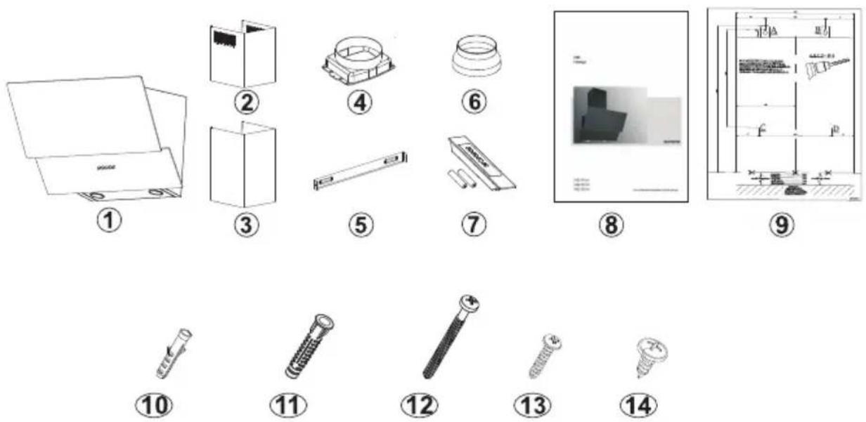
Fig. 9: CONTENT OF PACKAGE
1- Product
2- Inner Flue
3- Outer Flue
4- 150/120mm Plastic Flue
5- Flue Connection Plate
6- 150mm Flue Adapter (Option)
7- Remote Control (Optional)
8- User Manual
9- Installation Template
10- ∅6mm Plastic Dowel
11-∅10mm Plastic Dowel
12- 5.5x60 Wall Mount Screw
13- 3.9x22 Flue Connection Plate Screw
14- 3.5x9.5 Flue Connection Screw
9 OVERVIEW OF hood
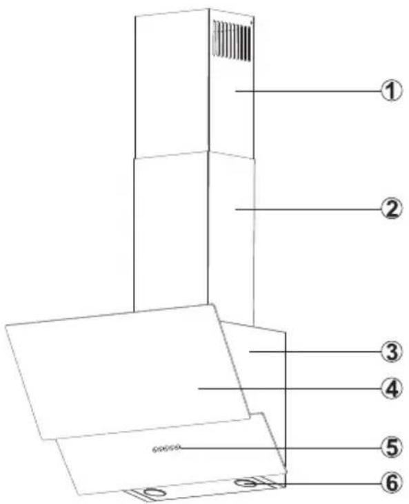
text_image
Technical diagram of a device with numbered components and labeled partsFig. 10: OVERVIEW OF hood
1- Inner Flue
2- Outer Flue
3- Body
4- Control panel
5- Side Suction Plate / Glass
6- Cooker Lighting
10 ASSEMBLY OF PRODUCT
10.1 Installation Diagram and Components

text_image
① ② ③ ④ ⑤ ⑥ ⑦ ⑧ ⑨ ⑩ ⑪ ⑫ F E Ø6 E,F B A C D Ø10 A,B,C,DFig. 11: ASSEMBLY INSTALLATION AND COMPONENTS
1- Inner Flue
2- Outer Flue
3- Glass
4- Hanging Plate of Cooker Hood
5- Hanging Plate of Cooker Hood
Fixing Screw
5- 2x 3.9x22 Flue Connection Plate Screw
6- Body
7-4x ∅10mm Plastic Dowel
8- 4x 5.5x60 Wall Mount Screw
9-2x 3.9x22 Screw
10- Flue Connection Plate
11-2x ∅6mm Plastic Dowel
■ Loosening the product hanging plate fixing screw (5) pull the hanging plates (4) upwards, and fix the hanging plated by re-tightening the fixing screw (Fig. 11).
■ Assemble the cooker hood with the help of the assembly scheme (Fig. 11).
Installation Diagram and Components
■ Affix the assembly pattern on the wall, at the specified height (See the minimum and maximum distances intended for the worktop, in the assembly pattern). Perforate points A, B, C and D (Fig. 11)
Insert ∅10mm wall plugs into the holes drilled as A, B, C, and D and screw down the screws at the points A + B, in such a way as to remain 5mm space between the screw head and the wall (Fig. 11)
- Hang it on the wall with the hanging plate of the cooker hood.
- Tighten A + B fixing screws on the wall, and completely secure the product at point D, C.
11 AIR EXIT INSTALLATION
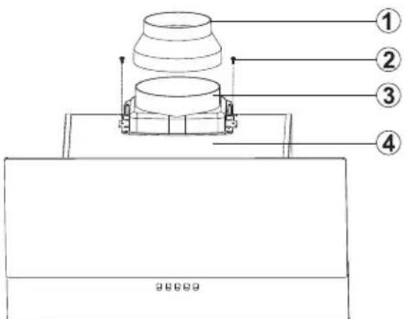
text_image
Technical diagram of a mechanical assembly with numbered components and a base plate labeled '20000'Fig. 12: PLASTIC FLUE CONNECTION
1- ∅150/120mm Flue Adapter (Option)
2- 2x 3.5x9.5 Screw
3- ∅120/150mm Plastic Flue (Option)
4- Body
■ When required, attach the connection part (1) on the plastic flue (3) and press firmly.
■ Install air exhaust connection of the appliance.
12 ASSEMBLY OF SHEET METAL FLUES
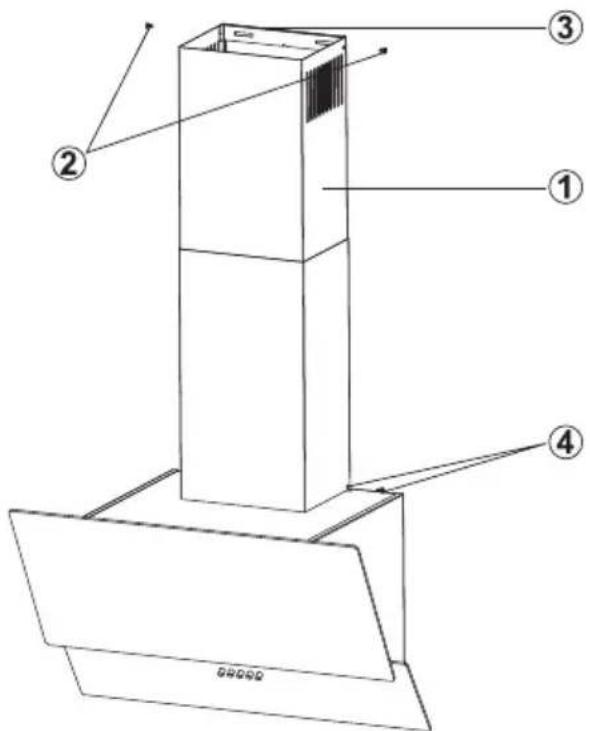
text_image
Technical diagram of a vertical shelf or lift structure with numbered components and directional arrows indicating assembly or flow.Pull up to left the Internal Flue (1) using screws (2) and screw it on the flue connection sheet on the right and left (3) (Fig. 13).
- Fix the exterior flue to the right and left connection sheet at the rear side of the hood body from the lower side using 2 screws (Fig. 13).
Fig. 13: SAC BACALARIN MONTAJI
1- Internal Flue
2- Flue Connection Sheet Fitting Screws
3- Flue Connection Metallic Sheet
4- Flue Lower Fixing Screws
Internal and external sheet flues are inserted to each other.
Flue connection sheet 3 is held directly on the wall under the cover by centering the Hood or measured and marked at points E, F. ().
Drill points E and F with ∅6mm drill and attach ∅6mm plastic pins. Attach flue connection sheet with 3.9x22 screws ().
13 USE OF PRODUCT
13.1 3 Spd Touch Product Usage


Fig. 14: Touch Button
- When this button is pressed, product will operate at speed level 1.
- When this button is pressed, product will operate at speed level 2.
- When this button is pressed, product will operate at speed level 3.
- Press this button to turn on or off the lamp.
To activate timer function, press and hold any of buttons ,; and for 3 seconds. When the timer function is activated the relevant button symbol will flash for 15 mins. Then, 15 minute timer function will be activated and the product will turn off automatically after 15 minutes.

After the activation of timer function, pressing any button will deactivate the timer function.

All active functions operated prior to activation of timer function will be deactivated after 15 minutes. All active functions operated after activation of timer function will be reactivated after 15 minutes.
13.2 Using Push Button Product
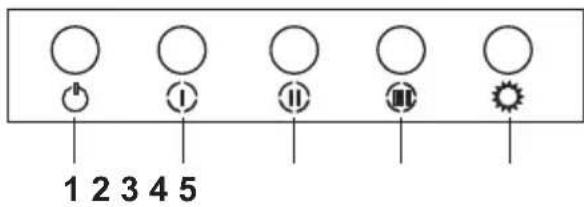
text_image
1 2 3 4 5Fig. 15: push button
- Press this button to reset your product.
- Product will run on 1st speed level when this button is pressed.
- Product will run on 2nd speed level when this button is pressed.
- Product will run on 3rd speed level when this button is pressed.
- Press this button to turn on and off the lamp.
14 REPLACING THE LAMPS
14.1 Halogen Lamp Replacement
WARNING
Disconnect the electrical supply of the hood. Leave the lamps to cool down first because they could burn your hands when they are hot.

It indicates the maximum power consumption of the lamp. A lamp with same power rating should be used when replacing the lamp.

To find out the power rating used in the product, see the declaration label in the product.

Fig. 16: Halogen lamp symbol
Only self-protection tungsten halogen lamp or self-protection metal halide lamp must be used.
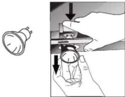
natural_image
Illustration showing a hand holding a small mechanical component with arrows indicating assembly or disassembly (no text or symbols present)Fig. 17: Halogen Lamp Replacement
For replacing the halogen lamps, push downwards on the lamp holder from its behind, turn it a little bit counter-clockwise, and take it out downwards. Fig. 17
14.2 Plug Lamp Replacement
WARNING
Disconnect the electrical supply of the hood. Leave the lamps to cool down first because they could burn your hands when they are hot.

text_image
-max 28 WPlug Lamp Replacement
It indicates the maximum power consumption of the lamp. A lamp with same power rating should be used when replacing the lamp.

To find out the power rating used in the product, see the declaration label in the product.
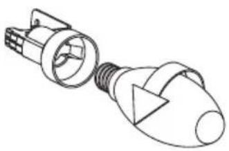
natural_image
Technical line drawing of a light bulb connector (no text or symbols)Fig. 18: Spark Plug Lamp Replacement
Remove the aluminium cartridge filter. Remove the faulty bulb and replace with a new one with the same rating. Fig. 18
15 AUTHORIZED SERVICE
If Lighting is Not Functioning:
■ Make sure that the plug is plugged in, and that the fuses are intact.
- Check the bulbs. Make sure you unplugged the device before performing this check. Tighten the bulbs if they are loose; you can replace the bulbs if they still don't work.
Possible Faults and Things that You can do Before Calling Technical Service:
A) If the device does not run in any way:
- Check to see if the hood is plugged in or if the plug is fit properly into the socket.
- Check the fuse, to which the appliance is connected, as well as the main fuse of your house.
If the device performance is not enough and it creates high noise while running:
Is the outlet diameter of the appliance's flue adequate? (min.120 mm).
Are the metal filters clean? Please check.
If you use the hood without flue, make sure that the carbon filters are not older than 6 months.
- Be attentive to ventilate your kitchen adequately, in order to provide an airflow. If you are still not satisfied with the performance of the appliance, consult the authorized technical service.
Troubleshooting
| Fault description Cause Remedy | ||
| Product Does Not Work | Check the power connection. | Mains voltage must be 220-240 V, and product must be plugged into a grounded socket. |
| Illumination lamp does not operate | Check the power connection. | Mains voltage must be 220-240 V, and product must be plugged into a grounded socket. |
| Illumination lamp does not operate | Check the lamp switch. | Lamp switch must be at "on" position. |
| Illumination lamp does not operate | Check the bulbs. | Bulbs must be operative. |
| Product's Air Intake is Weak | Check The Aluminium Filter. | The aluminium cartridge filter should be washed once a month under normal conditions. |
| Product's Air Intake is Weak | Check The Air Outlet Flue. | Air Outlet Flue Must Be Open. |
| Product's Air Intake is Weak | Check The Carbon Filter. | In products that work with carbon filters, carbon filter must be replaced once in every 3 months under normal conditions. |
| It Does Not Discharge Air (in flueless use) | Check The Aluminium Filter. | The aluminium cartridge filter should be washed once a month under normal conditions. |
| It Does Not Discharge Air (in flueless use) | Check The Carbon Filter. | In products that work with carbon filters, carbon filter must be replaced once in every 3 months under normal conditions. |
16 TECHNICAL TABLE
Supply Voltage 220 - 240 V 50Hz
Insulation Class F of Motor
Insulation Class CLASS I

text_image
CEThis product complies with the 2014/30/EC (Regulation on Electromagnetic Compliance) and 2014/35/EC (Regulation on Low Voltage Devices (LVD)) Directives.

natural_image
Symbol of a trash bin crossed with no text or labelsThis device complies with the Directive on the Control of Waste Electrical and Electronic Equipment.
Specifications of the device and this manual may be modified without prior notification.