
SVCI9080 - USB Drive SVAN - Free user manual and instructions
Find the device manual for free SVCI9080 SVAN in PDF.

| Product Type | Integrated Cooker Hood |
| Brand | SVAN |
| Model | SVCI9080 |
| Width | 90 cm |
| Cutout Dimensions (L x W) | 800 x 100 mm |
| Installation Type | Recessed in countertop |
| Operating Modes | Extraction or Recirculation |
| Duct Diameter | 150 mm |
| Motor Speeds | 4 levels + Boost |
| Boost Mode Duration | 7 minutes, then automatically reduces one level |
| Automatic Delayed Shutoff | 15 minutes after activation |
| Control Type | Touch panel and remote control |
| Lift Operation | Motorized, stops and reverses on obstacle |
| Lighting | Power-LED, automatic with lift after 20 cm |
| Voltage / Frequency | 220-240 V |
| Grease Filter | Metallic, washable (dishwasher safe up to 55°C) |
| Carbon Filter | Washable up to 3 times, replace every 3-4 months |
| Lamp Replacement | By qualified customer service only |
| Safety Features | Fire hazard warnings, children safety, automatic shutoff |
Frequently Asked Questions - SVCI9080 SVAN
User questions about SVCI9080 SVAN
0 question about this device. Answer the ones you know or ask your own.
Ask a new question about this device
Download the instructions for your USB Drive in PDF format for free! Find your manual SVCI9080 - SVAN and take your electronic device back in hand. On this page are published all the documents necessary for the use of your device. SVCI9080 by SVAN.
USER MANUAL SVCI9080 SVAN
natural_image
Exterior view of a modern office building (no signage)COOKER HOOD INSTRUCTIONS MANUAL
svan
C E
CAMPANA INTEGRADA 60CM_SVCI6080
CAMPANA INTEGRADA 90CM_SVCI9080
CAMPANA INTEGRADA 120CM_SVCI1280
SVAN TRADING SL CIUDAD DE CARTAGENA 20 (FUENTE DEL JARRO) PATERNA 46988 VALENCIA Spain
Telephone: +34 960 600 034
1, en_US
1 Safety notes
1.1 User's manual

natural_image
Simple icon of an open book (no text or symbols visible)Read this user's manual completely before you work with the hood.
Keep this manual in a safe place. When passing on the appliance to third parties, please also include the user's manual.
Strictly observe the precautions in order to avoid injury to persons and damage to the appliance.
The manufacturer assumes no liability for damages caused by non-observance of this user's guide.
This device is designed exclusively for domestic use.
1.2 Notes used

Important information for your safety are specially marked. Instructions must be strictly observed to avoid accidents and damage to the appliance
WARNING!
Warns of health hazards and indicates possible risks of injury.

natural_image
Yellow triangular warning symbol with black outline (no text or numbers)ATTENTION!
Indicates hazards for the appliance or other items.

CAUTION!
Indicates a potential hazard that could result in property damage if not avoided.

NOTE!
Indicates tips and information.
natural_image
Simple right-pointing arrow shape with no text or symbolsRefers to another chapter, a paragraph or note.
1 Safety notes
1.3 Children, special people

1.4 Intended use
Persons (including children) who are because of mental, physical or motor skills not able to use the appliance safely (special people), may not use the appliance without supervision or may use it only according under directives of a responsible person.
Do not leave the appliance unattended. Use with caution when children or special people who can not properly assess the hazards are nearby.
Packaging materials
- do not use to play. They pose the risk of suffocation.
- dispose of the packaging materials properly (☐ spare parts and disposal).
The range hood is intended only to clean the cooking fumes rising from the cooking area and for private use in the home.
- The appliance is for home use only.
- The appliance is not intended for commercial use.
- The hood is for use behind electric hotplates only.
- Any other use is considered improper and is prohibited.
Particularly refrain from:
- The operation of the range hood without metallic grease filter. Lack of the metallic grease filter leads to massive fatty deposits in the hood and the exhaust ducts.
- Flambéing near the range hood. It may lead to inflammation of the fatty deposits.
- Operation of the hotplate without cookware.
2 Unpacking and Installation
-Open flame can lead to inflammation in the hood.
-Cleaning the hood with agents or devices which are not specifically approved for this purpose, e.g. with a steam cleaner (Maintenance).
- Repair work carried out by unauthorized personnel (Customer Service).
1.5 Fire hazard
WARNING!
Risk of burns. Incorrect operation of the hood can cause burns.
- Duly comply with the maintenance and cleaning instructions
Basically refrain from:
- Cooking, frying and grilling with open flame due to fire hazard.
1.6 Power Supply

WARNING!
Electric shock. The hood is electrically operated. Incorrect installation, handling and operation can result in serious injury or death. Observe the safety notes.
2 Unpacking and Installation
1.7 Defective equipment

natural_image
Yellow triangular warning symbol with black outline (no text or numbers)ATTENTION!
Do not install or operate a defective hood. Repair work must be performed by qualified personnel authorized by the manufacture (▲ Customer Service).
Any intervention by unauthorized personnel terminates the guarantee and warranty claims (Warranty).
2 Unpacking and Installation
2.1 Unpacking

natural_image
Recycling symbol composed of three chasing arrows forming a triangle (no text or labels)The packaging materials are recyclable. Save resources and reduce waste generation. Feed the packaging items to the material recycling process again. Your dealer will take the packaging back
2.2 Installation and electrical connection

natural_image
Simple icon of an open book (no text or symbols visible)Observe the safety notes during installation and electrical connection (Safety notes) Read the installation instructions completely before installation.
Strictly observe the precautions in order to avoid injury to persons and damage to the appliance.
The manufacturer assumes no liability for damages caused by non-observance of this installation guide
2.3.1 Checking the hood parts
These include:
- Range hood and motor module
Accessories:
- 4 mounting brackets for hood housing
- Screws and washers for hood housing and motor module.
2 Unpacking and Installation
2.3.2 General information on installation
The hood is seated in the countertop (worktop) behind the hotplate.

WARNING!
Danger to life in case of damage to power lines. When drilling, supply lines (electricity, gas and/or water pipes) can be damaged. Before drilling get informed about courses of the supply lines (e.g. use a detector to locate metal and live wires).
2 Unpacking and Installation
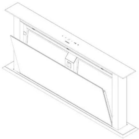
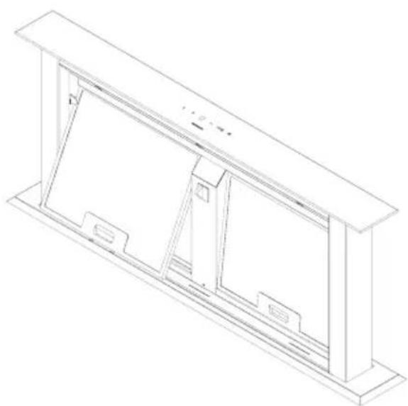
2.3.3 Installation drawings
natural_image
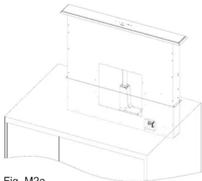
Isometric line drawing of a cabinet with a mounted box and a small inset box, labeled 'Fig. M2a' (no text or symbols on the diagram itself)Fig. M2a
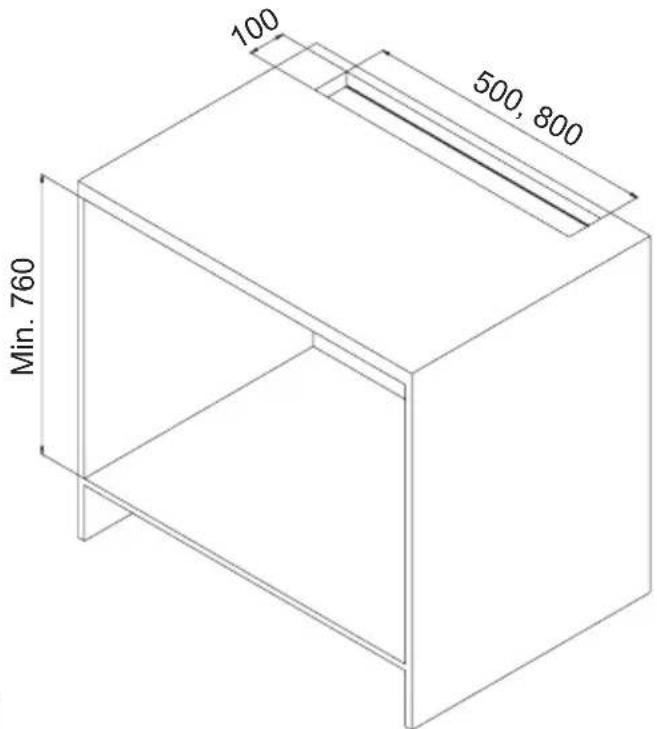
Fig. M1
natural_image
Isometric line drawing of a mechanical enclosure or enclosure with internal components and mounting brackets (no text or symbols)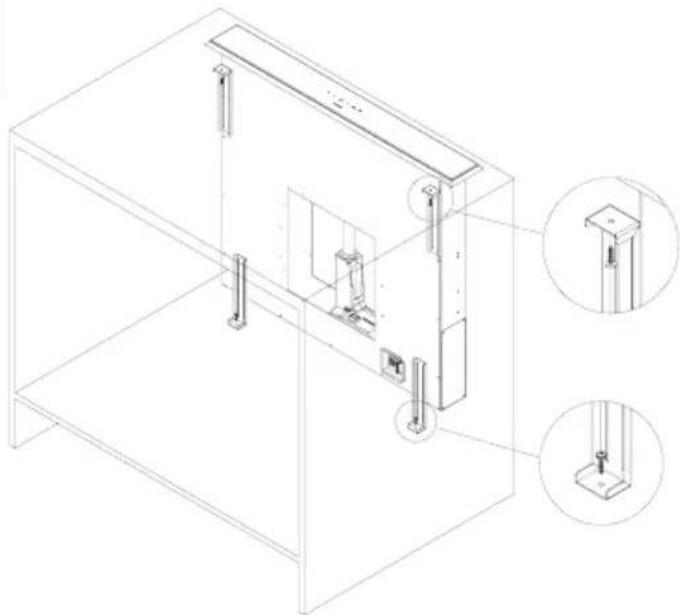
natural_image
Technical line drawing of a mechanical assembly with two views of a cabinet frame (no text or symbols)Fig. M2b
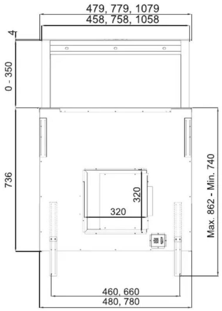
2.3.4 Dimensions of the appliance


2 Unpacking and Installation
2.3.5 Preparations for the hood assembly
- Using the mounting template, transfer the cutout size on the countertop to the desired location above the hob.
1. Cutout in the countertop
The cutout dimensions are:
3410 60:500x100 mm
3410_90:800x100 mm
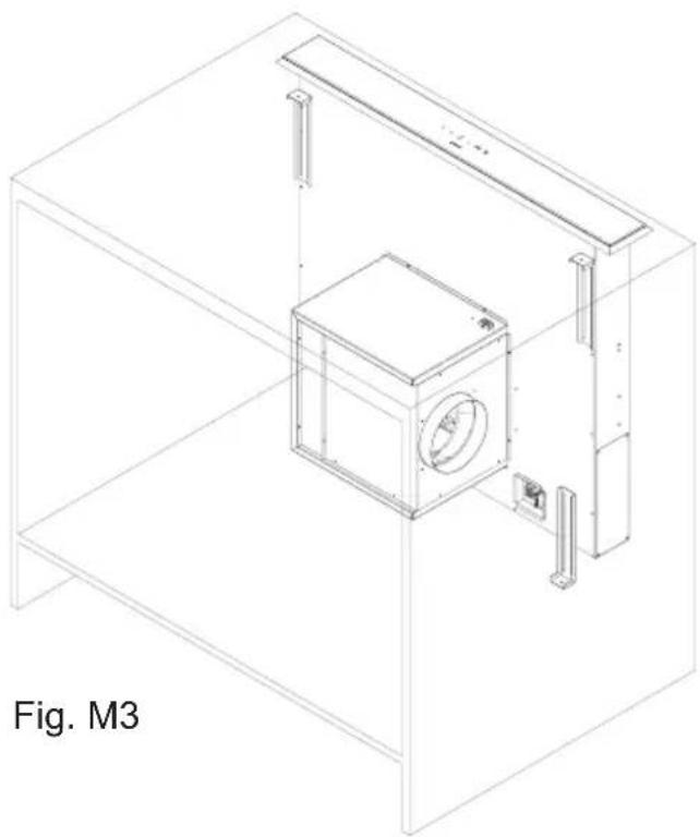
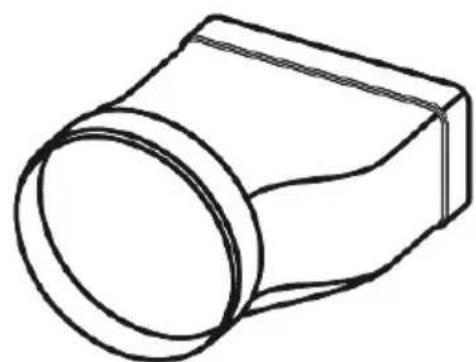
2. Motor module port direction for the exhaust duct
- You can connect the exhaust air from all directions to the hood (Fig. M3). For such purpose you can screw the motor module after the installation of the hood housing accordingly. For an air outlet to the front, the angle plate has to be unscrewed with the round vent connection and the engine below it, then rotated and screwed again.
3. Preparing the air duct for extraction mode or recirculation mode
Extraction mode:
Lay the exhaust duct with a diameter of 150 mm up to an already prepared wall penetration.
Recirculation mode:
The active carbon filter module must be placed so that the air is fed back into the kitchen area. In the skirting board, down on the side of the cabinet, etc., Use a round or flat air duct with a diameter of 150 mm.
We recommend a length of the air duct from the motor module to the circulating air module of not less than 180-200 mm, otherwise loud air noises may occur.
The active carbon filter module allows the connection of a flat channel with the dimensions of 222 x 89 mm
2 Unpacking and Installation
2.3.6 Installation of the hood 1. Position the cutout to the countertop. The
distance between the hob's edge and the hood's edge shall be max. 20 mm (see Figure M1).
ATTENTION!
Do not install or operate a defective hood. Repair work must be performed by qualified personnel authorized by the manufacturer
( ▲ Customer Service).
2. Installing the hood housing
Insert the hood housing into the cutout until you can carefully place the mounting sleeve on the countertop (fig. M2a).
Fasten with the mounting brackets the aligned, vertically positioned hood housing at the bottom of the cabinet floor (Fig. M2b).

natural_image
Line drawing of a rectangular electronic enclosure with mounting holes and mounting points (no text or symbols)Fig. 2: Electronics module
Fasten the motor module to the hood body
(Fig. M3). Pay attention to the blowing direction of the motor.
Connect the air channel as prepared for exhaust or recirculation.
Electrical connection of the electronics module with the motor/hood housing.
Plug the connection cable with 2 different couplings accordingly.
2 Unpacking and Installation
2.3.7 Hood for recirculation mode
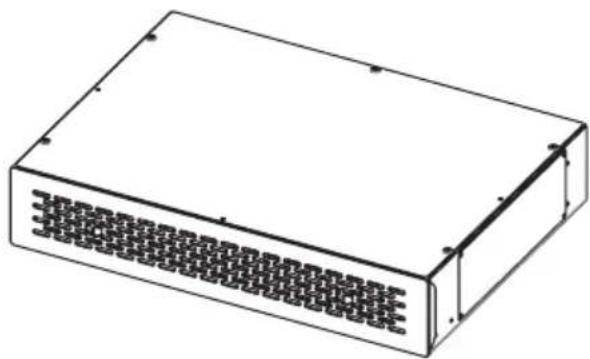
natural_image
Isometric line drawing of a rectangular electronic device with a grid-patterned front panel (no text or symbols)Fig 3: Recirculation module
To use this range hood in recirculation mode, install the recirculation module so that the aspirated air is blown through the recirculation module back to the kitchen area, e.g., through to the skirting board of the kitchen furniture, or the like.
The stainless steel front panel with drawer is locked with magnets in the module. To install and to remove later to change the carbon filter pads, draw towards the front the front panel with the drawer.

natural_image
Technical line drawing of a rectangular box with mounting holes and internal ribs (no text or symbols)Fig 3a
For carbon filter assembly fix a place under the bench.
Remove the sheet from the air outlet(Fig. 3a), screw the rectangle adaptor (Fig 3b)
Immobilize carbon filter box to a proper place from mounting holes
Affix one side of Round Flexible duct to the product, other side to the adaptor (Fig.3c)
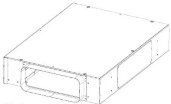
natural_image
Technical line drawing of a rectangular electronic enclosure with internal cavity (no text or symbols)Fig 3b
natural_image
Line drawing of a mechanical component with a circular end and rectangular body (no text or symbols)Fig 3c


Fig. 4: Touch control operation panel
3.1. Lift operation
The hood is in STANDBY mode when it is powered. In this state, the display shows nothing.
Moving the lift out
By touching the ↑ or ⚙ button, the lift moves up.
Info: As long as the lift is extended by less than 20 cm, the display will show a "0" after touching the button. When the lift is then raised by higher than 20 cm, nothing will be shown on the display. Neither motor nor light goes on in this condition.
After touching the ⚙ button, the light goes on after 20 cm of lifting height, but motor does not.
Stopping the lift or pulling it out again
By touching the arrow button ↑ or ↓ the lift is stopped and/or started in the direction of the arrows.
Info: The lift can be stopped or moved only after the height of 20 cm.
Lowering of the lift
By touching the ↓.
Info: After the lift has reached a height of less than 20 cm, the motor and the lights turn off, and the hood is in the standby mode. In this case, no indicator lights on the display.
3 Operation
Safety function when closing the lift:
3.2. Motor operation
3.3. Automatic delayed shutoff function switching and changing
In the event that any obstacle exists on the way of the lift when closing, e.g. a pot, dishes, hands, etc., the movement is stopped when the cover plate hits the obstacle and the lift then goes up again.
Motor on/off and changing the power settings
Each time the +/⑨ button is touched, the running stage increases by one step up to the max. Level 4 is reached. The display will shown in each case theselected running stage.
Touching the button decreases the running stage by one step each time; until the motor is switched off.
Nothing will be shown on the display then.
By touching the +/⑨ button for about 3 seconds, the automatic delayed shutoff function will be activated. The set running stage starts flashing on the display.
15 minutes after the activation of the automatic delayed shutoff function, the motor and/or the light will be switched off automatically.
The lift will remain stopped then.
To change the running stage within the set Automatic Delayed Shutoff Function time of 15 min, touch the button -or +/The Automatic delayed shutoff function will remain active.
The automatic delayed shutoff function can be turned off at any time within the 15 minutes.
To do this, the button+/☐ must be pressed for about 3 seconds.
3.4. Light on and off
The light goes on when the lift is extended
By touching the 🧑 button you can turn the back-light on or off.
Info: The lift must be extended to a height of 20 cm at the least.
The light goes off when the lift is fully down-By touching the 🎨 button the lift moves upward and after an height of 20 cm, the light turns on automatically. The motor remains off.
3.5. Power failure
In case of power failure, the lift remains stopped in its current position. After the power is resumed, motor and light stays off and the lift remains in its previous position. You can now operate the hood again, as described above.
3.6 Boost When the product is switched to maximum
speed while it is operated, a ( ) symbol shall be displayed on the screen. 'b' symbol indicates that boost (boost ventilation) mode is active on the model. Product shall operate for 7 minutes in this mode and 'b' symbol shall flash on the screen during this period. After 7 minutes, product shall automatically switch down one speed level and shall resume operation in the lower speed level.

NOTE!
It is not possible to use timer feature in the boost mode.
3 Operation
3.A. Hood operation with the remote control
3.A.1. Lift operation

natural_image
Line drawing of a remote control panel with four buttons (no text or symbols)Fig. 5: Remote control with buttons
The hood is in STANDBY mode when it is powered. In this state, the display shows nothing.
Pulling out the lift
By pressing the 🎨 button the lift will go up. When the lift reaches a height of 20 cm the light goes on; motor does not.
Info: As long as the lift is extended by less than 20 cm, the display will show a “0” after touching the button; when the lift is then raised by higher than 20 cm, nothing will be shown on the display
Stopping the lift or pulling it out again
By pressing the button + or - the lift will stop. By holding the buttons + pressed for about 3 seconds, the lift will be pulled out again.
Info: The lift can be stopped or moved only after the height of 20 cm.
Lowering of the lift
Press the — button for about 3 seconds.
Info: After the lift has reached a height of less than 20 cm, the motor and the lights turn off, and the hood enters the standby mode when the lift is lowered down completely. In this case, no indicator lights on the display.
3.A.2. Motor operation
Switching the motor on/off, and changing the power stages
Every single pressing of the ☐ button first switches on the engine and then increases the running stage by one step each, until the maximum stage 4 is reached. The display shows the selected running stage in each case.
Every single pressing of the — button first switches reduces the running stage by one step each; until the motor is switched off. The display will then show nothing.
The motor can be turned off by pressing the button.
3.A.3. Automatic delayed shutoff function switching and changing
The automatic delayed shutoff function is activated by pressing the ⏻ button for about 3 seconds. The set running stage starts to flash in the display of the hood.
15 minutes after the activation of the automatic delayed shutoff function, the motor and/or the light switches off automatically. The lift remains stopped.
To change the running stage within the set Automatic Delayed Shutoff Function time of 15 min, touch the button + or - The automatic delayed shutoff function will remain active.
The automatic delayed shutoff function can be turned off at any time within the 15 minutes. To do this, the button ⏻ must be pressed for about 3 seconds.
3 Operation
3.A.4. Light on/off
The light goes on when the lift is extended
By pressing the 🎨 button you can turn the backlight on or off.
Info: The lift must be extended to a height of 20 cm at the least.
The light goes off when the lift is fully down
By pressing the 🙏 button the lift moves upward and after an height of 20 cm, the light turns on automatically. The motor remains off.
3.A.5. Power failure
In case of power failure, the lift remains stopped in its current position. After the power is resumed, motor and light stays off and the lift remains in its previous position. You can now operate the hood again, as described above.
4.1 General maintenance notes

natural_image
Yellow triangular warning symbol with black outline (no text or numbers)
4.2 Cleaning of the hood
4.2.1 Notes for cleaning and care
ATTENTION!
The hood housing gets damaged if cleaned incorrectly. Discoloration may occur on the surfaces. Do not use any steam cleaner to clean the hood housing. Aggressive cleaning agents such as vinegar-based cleaners, abrasive cleansers, abrasive granules or pointed items must not be used.
NOTE!
Perform regular maintenance and cleaning of the range hood to ensure safety, function and performance.
Clean the range hood right after the installation and then when it is get dirty.
ATTENTION!
Remaining film adhesive residues on the stainless steel surface can lead to stains. Always clean the surface of the range hood thoroughly after the installation. For this purpose, use a cleaner that is specially suitable for stainless steel surfaces
Observe the following general notes for cleaning and care (also applies to painted glass surfaces):
- Before cleaning, remove any rings, watches and jewelry in order not to scratch the painted surface inadvertently.
- Always clean a large area in order to avoid selective chafing.
- Do not rub too hard on the material, so that no scratches and dull spots arise.
- Do not use abrasive or harsh cleaners or burnishes. Ingredients may damage the material.
- Be cautious in the use of sponges or rags. Residues can cause scratches.
4 Maintenance
- Immediately absorb and wipe dry fresh drops or spots (e.g. acidic liquids such as fruit juices) with a cloth.
- Do not pull or hit hot, heavy and sharp objects on top the painted surfaces.
Maintenance of stainless steel surfaces
Special stainless steel cleaning agents are suitable for the maintenance of stainless steel surfaces (▲Note below). They create a protective film that reduces fingerprints and facilitates the further maintenance.

NOTE!
For the care of stainless steel surfaces we recommend the Stainless Steel Care Spray, Order No. PS 500
4.3. Cleaning of the metallic grease filter

ATTENTION!
Fire hazard. An oversaturated metallic grease filter may lead to fires. Therefore, follow the maintenance and cleaning instructions.
ATTENTION!
Too frequent cleaning or the use of aggressive cleaning agents may cause damage to the mesh fabric of the metallic grease filters. For cleaning, only use a detergent suitable for this purpose (e.g. dishwashing detergent).
4.4 Metallic grease filter removal, installation and cleaning
natural_image
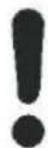
Isometric line drawing of a structural frame or enclosure with vertical supports and internal compartments (no text or symbols)Fig. 6a: Edge suction plate removal
- Pull the top edge suction plate forward and disengage from the locking latch. Thus, the hood gets immediately de-energized (Fig. 6a). Take out the edge suction plate upwards.
To remove the grease filter ( Fig. 6b) jpush the clip up and remove the filter forward/down respectively.
To insert the grease filter insert the upper pin by sliding it into the frame, press the clip, press filter onto the frame, and release the clip. Check whether the clip is properly engaged.
NOTE!
Securely hold the filter during handling, in order to prevent damage to the filter and the hotplate.
natural_image
Isometric line drawing of a rectangular enclosure or enclosure with internal compartments and supports (no text or symbols)Fig. 6b: Metallic filter removal/ installation
Cleaning of the metallic grease filter
To do this
- Soak the metallic grease filter well in hot soapy water, and clean it with a soft brush. Repeat the procedure if necessary.
- Rinse it well with hot water, and let dry.
- Repeat the process if the result is not satisfactory. The metallic grease filters are dishwasher safe (▲Note see below).
NOTE!
The metallic grease filter is dishwasher safe and can be cleaned using a program up to max. 55°C. Clean the grease filters separately due to possible fat deposits on the dishes. If heavily soiled, first soak in hot soapy water. Color changes on the metallic grease filter do not affect the function, and do not constitute any ground for complaint.
4 Maintenance
ATTENTION!
Too frequent cleaning or the use of aggressive cleaning agents may cause damage to the mesh fabric of the metallic grease filters. For cleaning, only use a detergent suitable for this purpose (e.g. dishwashing detergent).
CAUTION!
Performance is affected in case of undue maintenance intervals. Excessively long periods of use lead to clogging of the metallic grease filter and the active carbon filter with grease and dirt particles, resulting in severe impairment of the functionality of the hood. Therefore, please observe the maintenance intervals.
4.5 Recirculation mode operation with the Active Carbon Filter Pad and the Recirculation Module

natural_image
Isometric line drawing of a rectangular electronic device with a grid-patterned front panel (no text or symbols)Fig.7: Active Carbon Filter Pad and the Metallic Active Carbon Filter Module
4.5.1 Removal and installation of the carbon filter pad from and into the recirculation module
Remove the stainless steel front panel from the magnets towards the front. Pull out upwards the carbon filter pad which is now visible from the top. Reinsert the pad after washing or install a new one behind the stainless steel front panel, and push in the drawer contacting the magnets.
4.5.1 Washing of the carbon filter pad
The active carbon filter pad can be washed 3 times. The service period is 3-4 months under normal cooking conditions is, 2-3 months under frequent cooking practice, then it must be washed, or replaced with a new filter pad. It can be washed by hand or in a dishwasher at a standard program up to max. 55°C. Wash the pad alone in the dishwasher, so that no leftover food, etc., come into contact with the pad. Do not use any intensive stage, as otherwise damage could occur.
Leave the filter pad to dry in air, or in the oven at 80^ C max. for 40 minutes. If the active carbon filter pad is not washed regularly and replaced, louder motor noise and increased cooking smells may result in the kitchen
4 Maintenance
4.7 Lamp replacement

WARNING!
Risk of short circuit when replacing the lamp. The hood is electrically operated. Interrupt the power supply before changing the lamp.
natural_image
Technical line drawing of a mechanical assembly with no visible text or symbolsReplacement of the defective Power-LED
To do this:
The built-in power LED are very reliable and durable lamps.
Nevertheless, should a defect in the lighting arise, you can obtain the replacement lamps and replacement information through the customer service.
Fig. 8: Power-LED replacement
| Check electric connection(Voltage of the electric network should be between 220-240V, cooker hood should be connected to grounded plug.) | Check motor switch (Motor switch should be at on position) | Check motor switch (Motor switch should be at on position) | Check aluminum filter(Aluminum Cassette Filter should be washed once a month at normal conditions.) | Check lamps(Lamps should be firm.) | Check outlet (Outlet should be open) | Check Carbon Filter (Carbon filter should be replaced with a new one each 2-3 months at the models with Carbon Filter at normal conditions) | |
| Cooker-hood does not work | √ | √ | |||||
| Illumination Lamp does not work | √ | √ | √ | ||||
| Cooker-hoods air suction is weak | √ | √ | √ | ||||
| Cooker-hood does not direct air out (at places without chimney) | √ | √ |
4 Maintenance
4.8 If the product does not work:
Before you contact the technical service:
Make sure that the product is plugged in and the electric fuse of the electric wiring is running. Do not take any action that will damage the product. Before you contact with technical service, check your cooker hood according to Table 1. If the problem goes on, contact the seller or the most authorized service.
4.9 In order to use the cooker hood efficiently;
Use ducts of 150 mm diameter and as few bends as possible when you make the chimney connection.
Pay attention to aluminum filters' cleaning periods and changing periods of carbon filters.
Use the product at middle speed if high suction power is not necessary.
In order to ensure that ventilation occurs correctly, windows of the kitchen should be kept closed.


- COOKER HOOD INSTRUCTIONS MANUAL
- Safety notes
- User's manual
- Notes used
- WARNING!
- ATTENTION!
- CAUTION!
- NOTE!
- Children, special people
- Intended use
- Particularly refrain from:
- Unpacking and Installation
- Fire hazard
- Basically refrain from:
- Power Supply
- Defective equipment
- Unpacking
- Installation and electrical connection
- Checking the hood parts
- General information on installation
- Installation drawings
- Preparations for the hood assembly
- Cutout in the countertop
- Motor module port direction for the exhaust duct
- Preparing the air duct for extraction mode or recirculation mode
- Extraction mode:
- Recirculation mode:
- Installation of the hood 1. Position the cutout to the countertop. The
- Installing the hood housing
- Fasten the motor module to the hood body
- Electrical connection of the electronics module with the motor/hood housing.
- Hood for recirculation mode
- Lift operation
- Moving the lift out
- Stopping the lift or pulling it out again
- Lowering of the lift
- Operation
- Light on and off
- The light goes on when the lift is extended
- Power failure
- Boost When the product is switched to maximum
- 3.A. Hood operation with the remote control
- 3.A.1. Lift operation
- Pulling out the lift
- 3.A.2. Motor operation
- Switching the motor on/off, and changing the power stages
- 3.A.3. Automatic delayed shutoff function switching and changing
- 3.A.4. Light on/off
- The light goes off when the lift is fully down
- 3.A.5. Power failure
- General maintenance notes
- Cleaning of the hood
- Notes for cleaning and care
- Maintenance
- Maintenance of stainless steel surfaces
- Cleaning of the metallic grease filter
- Metallic grease filter removal, installation and cleaning
- Cleaning of the metallic grease filter
- To do this
- Recirculation mode operation with the Active Carbon Filter Pad and the Recirculation Module
- Removal and installation of the carbon filter pad from and into the recirculation module
- Washing of the carbon filter pad
- Lamp replacement
- Replacement of the defective Power-LED
- If the product does not work:
- In order to use the cooker hood efficiently;
Brand : SVAN
Model : SVCI9080
Category : USB Drive