GSHC5000 - Security Camera UNIDEN - Free user manual and instructions
Find the device manual for free GSHC5000 UNIDEN in PDF.

User questions about GSHC5000 UNIDEN
0 question about this device. Answer the ones you know or ask your own.
Ask a new question about this device
Download the instructions for your Security Camera in PDF format for free! Find your manual GSHC5000 - UNIDEN and take your electronic device back in hand. On this page are published all the documents necessary for the use of your device. GSHC5000 by UNIDEN.
USER MANUAL GSHC5000 UNIDEN
GSHC1000/3000/5000 Series Guardian Smart Home Control
For more exciting new products please visit our website:
Australia: www.uniden.com.au
OWNER'S MANUAL
IMPORTANT SAFETY INSTRUCTIONS
When using your equipment, always follow basic safety precautions to reduce the risk of fire, electric shock and injury to persons, including the following:
- The units are NOT waterproof. DO NOT expose it to rain or moisture (for the weatherproof IP camera (App Cam 25): DO NOT expose it to excessive water or moisture).
- DO NOT immerse any of the units in water. Do not use any of the units near water, e.g., near a bathtub, wash bowl, kitchen sink or laundry tub, in a wet basement or near a swimming pool.
- To avoid any risk of electric shock from lightning, avoid handling any electronic devices (except battery powered ones) during an electrical storm.
- Use only the power cord and/or batteries indicated in this manual. Never dispose of any batteries in a fire: they may explode. Check with local codes for possible special disposal instructions.
- Never tug or pull on any power cord: be sure to leave some slack in the cord when placing your equipment, and always use the plug to unplug cord from the wall outlet.
- Never leave power cords where they can become crushed, cut, or frayed; when running power cords, avoid letting them rub against any sharp edges or lie across any high traffic areas where people might trip over them.
- Do not use the units if the adaptor cords or plugs have been damaged, the units have been exposed to liquids, or the units have been dropped or is damaged.
For best results:
To avoid damage to your equipment, follow these simple precautions:
- Do not drop, puncture or disassemble any part of the equipment. There are no user-serviceable parts inside.
- Do not expose the equipment to high temperatures, and avoid leaving the equipment in direct sunlight for more than a few minutes. Heat can damage the case or electrical parts.
- Do not place heavy items on top of the equipment or expose the equipment to heavy pressure.
- Remove the power adaptor during long periods between usages.
-
Clean only with a dry cloth.
-
STRANGULATION HAZARD. Keep the adaptor cords out of the reach of children.
- WARNING: KEEP OUT OF THE REACH OF CHILDREN. Allow for proper ventilation when units are in use. Do not cover any of the units with any object such as a blanket.
Failure to follow the instructions in this owner's manual will void the warranty. Uniden assumes no liability for damages to property or injury to persons caused by improper handling or failure to comply with these safety instructions.
CONTENTS
Important Safety Instructions 2
Introduction .... 5
What's In The Box 7
Getting to Know Your Devices .... 8
Gateway 8
Remote Key 8
Door/Window Sensor 9
Motion/PIR 9
Indoor Siren 10
App Cam 24 ....10
App Cam 25 ......11
App Cam 26 ....12
Setting Up The System 13
Download the App 13
Install the Gateway/Connect to Internet 13
Set Up Your System 13
Activate The Sensors 14
Connect The Indoor Siren 14
Pairing the Cameras ....15
Manual Pairing 21
The GUARDIANHOME App 24
TROUBLESHOOTING 37
SPECIFICATION 38
WARRANTY 40
INTRODUCTION
Thank you for buying Uniden's Guardian Smart Home Control Kit!
The Guardian Smart Home Control is the smart way of securing your home. It consists of Gateway, Door/Window Sensors, Indoor Siren, Motion/PIR Sensor, Remote Key and indoor/outdoor IP Cameras. All the senors/devices/IP cameras work in conjunction with the Gateway to keep a close watch on your property and alert you when required.
We offer a range of packages to smarten up your home.
The Starter Kit (GSHC1000): This is the basic kit and includes one Gateway Hub, three Door/Window Sensors, two Remote Keys and an App Cam 24.
The Outdoor/Indoor Kit (GSHC3000): This kit offers an outdoor IP Camera (App Cam 25) and an indoor IP Camera (App Cam 24) along with one Gateway Hub, three Door/Window Sensors, two Remote Keys, one Motion/PIR Sensor and one Indoor Siren.
The Deluxe Kit (GSHC5000): This luxury kit offers two Pan/Tilt indoor IP Cameras (App Cam 26) along with one Gateway, five Door/Window Sensors, two Remote Keys, two Motion/PIR Sensors and one Indoor Siren.
When you buy any of our kits, please refer to the ‘what’s in the box’ section to ensure that you have all the items listed, for the kit you purchased.
Need Help? Get answers at our website: www.uniden.com.au for Australian model.
If any items are missing or damaged, contact your place of purchase immediately. Never use damaged products!
Now, let's look at a possible scenario of how you could install the Gateway, various sensors, Indoor Siren and the App Cams, in your home.
In the graphic illustration below, the Gateway Hub, the Indoor Siren, Motion/PIR Sensor and the App Cam 26 have been set up in the living room. There is a Door/Window Sensor installed on the kitchen door and an App Cam 24 set up in the nursery. The Remote Keys have been left in the master bedroom for easy access and, the App Cam 25 has been installed outside.
You can set up the sensors and the camera based on your convenience. The illustration below is just to help you get started.

text_image
Gateway Smart wireless central home control / management center. Adaptor DC 12V/1A Adaptor DC 5V Battery CR2032 Remote Wireless multi-functional remote controller. APPCAM24 Wireless day/night portable motion alert indoor camera. APPCAM25 Wireless day/night portable motion alert outdoor camera. Adaptor DC 5V/1.5A
text_image
Diagram of a multi-level home appliance layout with labeled appliances and fixtures, including lighting, kitchen, and bathroom fixtures.
text_image
Motion PIR Wireless portable/wall- mount area motion alert sensor. Battery AA 1.5V x 3
text_image
Wireless day/night portable motion alert indoor camera Adaptor DC 5V/1.5A
text_image
Indoor SirenAPPCA Wireless portable/wall- mount alert siren. Adapler DC 5V/1A or Battery AA 1.5V x 4 (not included)
text_image
M26or/Window Sensor Wireless door/window access alert sensor. Battery CR2032WHAT'S IN THE BOX
| CONTENTS GSHC1000 | GSHC3000 | GSHC5000 | ||
GATEWAY |  torCable torCable | 1 1 1 | ||
REMOTE KEY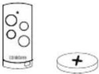 Battery Battery | 2 2 2 | |||
MOTION/PIR SENSOR - 1 2 | BatteryAdhesive PadWall Mount BracketWall Mount Screw | |||
DOOR/WINDOW SENSOR | BatteryAdhesive PadNall Mount Screw | 3 3 5 | ||
INDOOR SIREN | adaptorMount BracketMount Screw | - 1 1 | ||
APPCAM24 | AC AdaptorEthernet Cable | 1 1 - | ||
APPCAM25 - 1 - | AC AdaptorAntennaEthernet-to-USB CableStand | |||
APPCAM26 |  AC AdaptorAntennaEthernet CableBracket AC AdaptorAntennaEthernet CableBracket | - - 2 | ||
GETTING TO KNOW YOUR DEVICES
In this section, we will take a look at the each of the sensors/devices/IP cameras included in the Guardian Smart Home Control package.
Gateway
The Gateway (GSHC-GW) is the head of the Guardian Smart Home Control system. It connects to the internet via your router to enable you to control and access your Guardian Smart Home system from your mobile devices.

text_image
Speaker Power LED Network LED Uniden 12V=1A RESET Reset DC12V Port WAN portRemote Key
The Remote Keys (GSHC-RM) can be used to arm or disarm the system, activate camera recording and set off the Indoor Siren.
| Button How it Works? | |
| Arm Press | to arm the system. |
| Disarm Press | to disarm the system. |
| Record Press | and hold to start camera recording. |
| Panic Press | ss and hold to set off Indoor Siren, and camera recording. |

text_image
LED Arm Disarm Record Panic UnidenDoor/Window Sensor
The Door/Window Sensor (GSHC-MD) monitors the entrances to your home.

text_image
LED Uniden Battery CoverMotion/PIR Sensor
The Motion/PIR (GSHC-PIR) Sensor uses the passive infra red technology to detect movement in a monitored area.

text_image
Button (Press to open the battery cover) Uniden LensIndoor Siren
The Indoor Siren (GSHC-SIR) produces a powerful 110db siren and has a flashing LED light. It is weatherproof and can function on batteries too.

text_image
Uniden LEDApp Cam 24
The App Cam 24 is an indoor wireless IP Camera that offers day/night on site/remote live viewing, recording and storage.

text_image
PIR Sensor Lens Light Sensor Reset MicroSD Card Slot Microphone Link LED Power LED LAN Port Speaker PowerApp Cam 25
The App Cam 25 is an outdoor, wireless, weatherproof IP Camera that offers day/night on site/remote live viewing, recording and storage.

text_image
Antenna Infrared LEDs Power LED Link LED PIR Sensor Camera Stand SMA Connector USB to RJ-45 RJ45 MicroSD Card slot Power Cable / Reset ButtonApp Cam 26
The App Cam 26 is an indoor, wireless, IP Camera that offers day/night on site/remote live viewing, recording and storage.

text_image
Light Sensor Infrared LEDs Microphone
text_image
LAN Port Antenna Connector Reset Link LED Power Input MicroSD Card SlotSETTING UP THE SYSTEM
Please ensure that your Gateway and mobile device is connected to the same WiFi router for the initial setup.
Step 1: Download the App
Download the Uniden GuardianHome App from the Apple App Store or Google Play.

Step 2: Install the Gateway/Connect to Internet
- Connect the Gateway to the WiFi router using the Ethernet cable (provided).
- Connect the Gateway to a power outlet using the AC adaptor (provided).
- The Gateway announces, "Power On" and the Power LED on the Gateway glows blue.

natural_image
Diagram of a router connected to a network device via a cable (no text or symbols present)- The Gateway announces, "Network Connected", when a connection to the internet is established, and the Network LED on the Gateway glows green.
Step 3: Set Up Your System
- Launch the App.
- Tap to confirm that you have connected the Ethernet cable.
- Tap▶ again to confirm that the system has been powered on.
-
The App looks for the Gateways' DID through its connection on the home WiFi. Name the Gateway. Enter the default security code (123456) and tap 📋. (If the App cannot find the Gateway's DID, ensure that the Gateway is powered on and connected securely to the router. Ensure that your mobile device is also connected via WiFi to your router. Enter the DID manually. The DID is located on the bottom of the Gateway. It is highly recommend that you change the default security code through the Settings screen (Refer page 31).
-
Tap the Gateway listing to log in. The Status screen with all of the sensors that are paierd to the Gateway displays.

text_image
Searching Or tap "Next" to manually enter "System DID". Searching
text_image
Please name your system and assign a new system password System Name: System Name System DID: Security Code: ********
text_image
System USHC41 FPP USHC41 Tap to select preferred GATEWAY.
text_image
Status Status Scenario Event SettingStep 4: Activate The Sensors
PLEASE NOTE: For your convenience, we have pre-paired the sensors (Remote Key, Door/Window Sensor, Motion/PIR Sensor) to the Gateway.
Please take off the insulating plastic tag on the sensors to activate them. Please refer to the images below.

natural_image
Diagram showing a refrigerator with a red circular object and a black arrow pointing to it (no text or symbols)Door/Window Sensor

natural_image
Simple illustration of a battery with a red cap and black arrow pointing to its left side (no text or symbols)Motion/PIR Sensor

natural_image
Diagram of a device with a red arrow pointing to a component, no text or symbols presentRemote Key
However, if you encounter problems with any of the sensors/devices or if you purchase additional sensors/devices, please refer to the manual pairing instructions to pair the relevant sensor to the Gateway (Refer page 17).
Step 5: Connect The Indoor Siren
PLEASE NOTE: For your convenience, we have pre-paired the Indoor Siren to the Gateway.
Please connect the Indoor Siren to the power outlet using the supplied AC adaptor or insert 4 x AA batteries into the battery compartment to power up the Siren.

text_image
Diagram showing electrical connection with battery, resistor, and battery holder, labeled OR indicating or without charging.However, if you encounter problems with the Indoor Siren or if you purchase an additional Indoor Siren, refer to the manual pairing instructions.
Step 6: Pairing the Cameras
App Cam 24
The App Cam 24 is included in the GSHC1000 (Starter Kit) and the GSHC 3000 (Outdoor/Indoor Kit) and does NOT come paired to the Gateway.
Connecting to the Gateway
Follow the steps below to pair the App Cam 24 to the Gateway.

natural_image
Line drawing of a smart TV device with a circular lens and stand (no text or symbols)-
First connect the camera to the Wi-Fi router via the Ethernet cable supplied.
-
Power on the camera using the AC adaptor supplied and wait until both the LEDs glow steady.
Note: DO NOT begin the APP setup process until both LEDs glow steady.
- Launch the GuardianHome App, select the Gateway, tap + in the 'Status' screen and tap to add a new camera to the Gateway.
Tap ▶. The App will now search for the camera connected to the Wifi Router and pull in the camera DID.
-
Tap if search didn't produce any result and you would like to manually enter DID (15 characters). (DID can be found on the back of camera).
-
Please name your camera and specify the location where the camera will be installed. The camera's default security code is '123456'. Tap 📋 to complete pairing the camera to the Gateway.

text_image
Select Device Camera Siren RemoteKey DoorSensor MotionSensor PowerSwitch Status Scenario Event SettingApp Cam 25
The App Cam 25 is included in the GSHC 3000 (Outdoor/Indoor Kit) and does NOT come paired to the Gateway.
Connecting to the Gateway
Follow the steps below to pair the App Cam 25 to the Gateway.

natural_image
Technical line drawing of a mechanical device with no visible text or symbols
text_image
Select Device Camera Siren RemoteKey DoorSensor MotionSensor PowerSwitch Status Scenario Event Setting-
First connect the antenna to the camera. Then connect the camera to the Wi-Fi router via the Ethernet cable supplied.
-
Connect the antenna and power on the camera using the AC adaptor supplied. After about 45 seconds, the red LED is steady on and the green LED begins to flash (3-flash/pause pattern), indicating that the camera is in Pairing mode. and wait until both the LEDs glow steady.
- Launch the 'Guardian Home' App, select the Gateway, tap + in the 'Status' section and tap to add new camera to the Gateway.
Tap ▶ the App will now search for the camera connected to the Wifi router and pull in the
camera DID.
- Tap▶ if search didn't produce any result and you would like to manually enter DID (15 characters). (DID can be found on the back of camera).
- Please name your camera and specify the location where the camera will be installed. The camera default Security Code is '123456'. Tap ☐ to complete pairing the camera to the Gateway.
App Cam 26
The App Cam 26 is included only in the GSHC5000 (Deluxe Kit) and does NOT come paired to the Gateway.
Connecting to the Gateway
Follow the steps below to pair the App Cam 26 to the Gateway.
- First connect the camera to the Wi-Fi router via the Ethernet cable supplied.
- Connect the antenna to the camera. You can attach the camera stand to the camera as well, but it is not necessary.
-
Connect the camera to power. After about 45 seconds, the camera goes through a pan/tilt cycle and the green LED begins to flash (3-flash/pause pattern).
-
Launch the GuardianHome App, select the Gateway, tap + in the 'Status' section and tap 🔒 to add new camera to the Gateway. Tap 🔒. The App will now search for the camera connected to the Wifi Router and pull in the camera DID.
-
Tap if search didn't produce any result and you would like to manually enter DID (15 characters). (DID can be found on the back of camera).
-
Please name your camera and specify the location where the camera will be installed. The camera's default security code is '123456'. Tap 📋 to complete pairing the camera to the Gateway.

natural_image
Technical line drawing of a mechanical component with circular and rectangular features (no text or symbols)
text_image
Select Device Camera Siren RemoteKey DoorSensor MotionSensor PowerSwitch Status Scenario Event SettingChanging the Camera's Connection from Wired to Wireless
Once you have paired the App Cam 24, 25 or 26 you can change the connection from wired (ethernet cable) to wireless (WiFi).
- For camera to work wirelessly with the Gateway, you will need to add router to App. Ensuring that the camera is connected to the router via Ethernet cable, go to Status, tap ☑ Edit on upper right and select Ⓞ Camera Edit to enter camera info.
- In camera info section, tap ✪ and enter camera password (default: 123456) to enter Advanced Settings. In Wi-Fi setting section, choose the router and enter its password. Camera will automatically reboot. Now, please remove the Ethernet cable, and wait until GREEN LED indicator become steady on. Now, the camera can operate wirelessly.

text_image
ON on Table OFF PID 在最角 遥控器 Status Scenario Event SettingInstalling the Cameras
App Cam 24
- Hold the base of the camera stand where you want to mount it and mark the location of the screw holes.
- Use the included screws and anchors to attach the base to the wall or ceiling. You can also attach the base into a flat surface such as a tabletop if needed.
- Before attaching the camera, tug gently on the stand to make sure it is securely in place.
- Disconnect power to the camera.
-
Attach the camera to the mounting screw. Set the mounting post to the correct angle (up to 90° movement). Tighten the circular camera brace up against the App Cam 24 to secure it into place.
-
After installation, reconnect power.

natural_image
Diagram showing a mechanical assembly with a lever and two screws connected to a vertical panel (no text or symbols)
text_image
Camera BraceApp Cam 26
-
Hold the mounting plate where you want to mount it and mark the location of the screw holes.
-
Use the included screws and anchors to attach the mounting plate to the wall.
-
Use the enclosed screws to screw the camera to the bracket.

natural_image
Two identical illustrations of a surveillance camera with antenna and sensor components, shown from different angles (no text or symbols visible)App Cam 25
-
Hold the base of the camera stand where you want to mount it and mark the location of the screw holes.
-
Use the included screws and anchors to attach the base to the wall or ceiling. You can also screw the base into a flat surface such as a tabletop if needed.
-
Before attaching the camera, tug gently on the stand to make sure it is securely in place.

natural_image
Technical illustration of a mechanical assembly with two views: one showing a pipe with bolts and the other showing a vertical cylindrical component with fasteners (no text or symbols present)
flowchart
graph TD
    A["1 Attach the camera to the mounting screw and turn it to the desired direction."] --> B["2 Tighten the brace against the camera to secure it in place."]
    B --> C["3 Loosen the wingnut to unlock the mounting post."]
    C --> D["4 Adjust the post to the correct angle, then tighten the wingnut to lock the post into place."]
- For the App Cam 25, attach the camera bracket to the mounting screw. You can attach the stand to the top or the bottom of the camera as needed. Tighten it a few turns, then turn the camera to face the direction you want.
- Tighten the camera brace up against the App Cam 25 to secure it into place.
- Unlock the mounting post by turning the wingnut to the left a few turns.
- Set the mounting post to the correct angle, then tighten the wingnut until the post is locked into place.
- After the App Cam 25 camera is installed, reconnect power.
Manual Pairing
All sensors and the Indoor Siren have been pre-paired out of box. However, should you encounter connection problem, or if you buy additional sensors/Indoor Siren, please refer to the manual pairing instruction below.
Tap from the Status screen to add a sensor. The GuardianHome App displays a list of devices. Select the desired sensor and follow the relevant steps below.

text_image
Select Device Camera > Door Sensor > Motion Sensor > Remote Key > Siren > Power Switch >Door/Window Sensor
- Select Door/Window Sensor from the Select Device screen, by tapping the arrow (✗) next to it.
- Tap 📍 to initiate the pairing process and then remove and reinstate the battery cover.
- Enter the 'Device Name', 'Location' and tap to complete the pairing process.
- The Door/Window Sensor will now display in the App's 'Status' section.
- Repeat this procedure for each of the Door/Window Sensor.

natural_image
Diagram of a mechanical device with internal components and directional arrows, no visible text or symbols
natural_image
Diagram of a door lock mechanism with arrows indicating movement (no text or symbols)Install the Door/Window Sensor
- After the Door/Window Sensors are paired to the Gateway through the App, apply the adhesive pads to the back of the sensor.
- Select a location, eg, the door/window frame. Place the larger part of the sensor on the frame and press to adhere. Line up the smaller piece to the larger one and press on the door or window.
The gap between the two parts of the sensor should not exceed 0.5 inches.
Motion/PIR Sensor
- Select Motion/PIR Sensor from the Select Device screen, by tapping the arrow ( ) next to it.
- Tap to initiate the pairing process and then press the 'pairing' button located inside the battery compartment.
- Enter the 'Device Name', 'Location' and tap to complete the pairing process.
- The newly paired sensor will now display in the App's 'Status' section.
- Repeat this procedure for each of the Motion/PIR Sensors.

natural_image
Line drawing of a battery pack with three cylindrical cells and a finger inserted, showing internal components (no text or symbols)Install the Motion/PIR Sensor

text_image
16 meters(A) Using Adhesive Tape

natural_image
Pure mechanical diagram showing a rectangular block with internal components and directional arrows, no text or symbols present.(B) Using Wall-Mount Bracket

natural_image
Technical line drawing of a mechanical assembly with a vertical component (no text or symbols)- After the Motion/PIR Sensors are paired to the Gateway through the App, apply the adhesive pads to the back of the sensor.
OR
- Fix the bracket on the back of the Motion Sensor and then using the screws mount it on a wall.
The detection distance is up to 16m.
Indoor Siren
- Select Siren from the Select Device screen, by tapping the arrow ( ) next to it.
- Tap 📋 to initiate the pairing process and press the 'pairing' button located inside the battery compartment.
- Enter the 'Device Name', 'Location' and tap ↓ to complete the pairing process.
- The newly paired Indoor Siren will now display in the App's 'Status' section.
- Repeat this procedure for each of the Indoor Sirens.

text_image
AA 15V,LR6 AA 15V,LR6 AA 15V,LR6 AA 15V,LR6Install the Indoor Siren

natural_image
Diagram showing a device with four buttons and a magnified inset of its internal components (no text or symbols)It is recommended to install the Indoor Siren in a highly visible location with minimum obstacles for maximum alert.
Fix the bracket on the wall using the mounting screws provided and then place the unit on it.
Remote Keys
- Select Remote Key from the Select Device screen, by tapping the arrow ( ) next to it.
- Tap to initiate the pairing process and press and hold the 'camera' button located on the unit, until the blue LED begins flashing.
- Enter 'Device Name', 'Location' and and tap ↓.
- The newly paired Remote Key will now display in the App's 'Status' section.
- Repeat this procedure for each of the Remote Keys.

natural_image
Illustration of a hand pointing at a device with a magnifying glass and circular components (no text or symbols)THE GUARDIANHOME APP
Using the GuardianHome App, you can access Uniden's Guardian Smart Home sensors/devices from anywhere. Use the App to set up scenarios, arm or disarm sensors, display events, set up email alerts, push notifications and configure your system.

natural_image
Green and white icon of a house with a stylized 'U' inside, no text or symbols present.Please refer to page 12 for details on how to download the App, connect the Gateway and set up your system.
Status Screen
The Status screen is the primary screen in the GuardianHome App.

text_image
Add sensor/device Arm/Disarm status Return to previous screen Status Edit fields on current screen 26 Location ON Siren sos Location OFF Door Sensor Location Door Sensor Location Door Sensor Location Door Sensor Location Display's current status of all sensors Set up customised security sequences Displays list of all triggered events Allows system configurationView the Status of the Sensors/Devices on the App
Using the GuardianHome App, you can view the status of your sensors.
- Open the GuardianHome App and tap the System Name.
- The Status screen displays the sensors/devices/cameras paired to that system and a set of icons to access other functions.
The Status screen also allows you to do the following:
| + | Add Sensor/Device | Select this icon to pair another sensor/device to your system. |
| Arm/Disarm the system | Tap the icon to arm or disarm a group of sensors. The Gateway beeps when you arm the system and you have 30 seconds before the sensors are fully armed. | |
| Edit Tap on this icon | and the Settings and Delete icons display on the Status screen, near the sensors/devices/cameras.Tap on the Settings icon on the Door/Window sensor, Motion/PIR sensor and the Remote Keys to to edit the name of the sensor/device and location. For the Door/Window sensor, you also have the option to set the ‘Entry Delay Time’ for up to 30 seconds. This option, when activated, gives you time to disarm the system before the system sounds the alarm.Tap on the Settings icon on the Indoor Siren to to edit the name of the device, location and increase or decrease the volume.Tap on the Settings icon on the App Cam 24, 25 and 26 to edit the name, DID, security code and location. With the cameras, you can tap the Advanced Setting icon to configure more settings. | |
| Display Status Displays sensors' current status and allows operation (turn on siren, etc). | ||
| Set up Scenario Sets up one-touch scenarios (Arm or Panic) or If...Then scenarios (pre-determined sequences where an event on one sensor will trigger other devices). | ||
| Display Event Displays a list of events resulting from sensors being triggered. | ||
| Configure Setting | Allows system configuration such as IP Setup, Security Setup, Notification Setup, Schedule Setup, etc. | |
Alert Icons
Alert icons display on the Status screen for a particular sensor/device when it has been triggered, tamepered with or the battery is low.
Types of alerts and their icons are given below:
| Icon What it Indicates? | |
 | Indicates that the Door/Window sensor is closed. |
 | Indicates that the Door/Window sensor has been opened. |
 | Indicates that the sensor/device is on. |
 | Indicates that the sensor/device is off. |
 | Indicates that the sensor/device has been triggered. |
 | Indicates that the sensor is low on battery. |
 | Indicates that the sensor/device has been tampered with (taking off the battery cover). |
 | Tap to delete a sensor/device. |
 | Tap to get into the settings of a particular sensor/device. |
Access the Status screen. It displays sensors paired to the system and a set of icons to access other functions
In this example, the back door sensor has been triggered. The icon displays.
Tap on the alert icon to clear it.
The 📄 icon displays, showing that you have acknowledged the sensor alert and the door is still open.
Please find below an image of the Status screen, displaying the various alert/edit icons.

text_image
Status Siren sos Location OFF Motion Detect or 2 ! Motion Detect or 1 ! door sensor 1 door sensor 2 window sens or 5 window sens or 4 Status Scenario Event Setting
text_image
Status Back Door Back Door Front Door Front Door Status Scenario Event SettingScenarios
Scenarios can be best defined as a series of preset sensor actions triggered by an event. The GuardianHome App allows you to set up scenarios, using a combination of all the sensors/devices, to alert you in case of any event. When you tap Scenario ( ), the Scenario screen displays. The screen is divided into two sections along with a set of icons at the bottom.

text_image
Scenario ARM Camera Panic One-Touch Scenarios If...Then Scenarios Door Sensor Front Door ON OFF Window Sensor Living Room ON OFF Icon Bar Status Scenario Event SettingThe top section, is what we will refer to as, One-Touch scenario. In this section, you can set up specific sensors by just tapping on the relevant icon.
Let's take a look at the different options available under the One-Touch scenario.
ARM: You can choose to arm, or partially arm selected device(s) and sensor(s). When you arm the system, the Gateway beeps and a 30 second countdown screen displays. After 30 seconds, a confirmation message, "System is now armed", displays on the screen. Only after you have armed the system you will be able to receive Email Alert/Push Notification.
CAMERA: Tap to activate selected camera(s) for sudden recording requirements.
PANIC: Activate selected camera(s) or Indoor Siren(s) for emergency recording or to sound an alarm.
The bottom section contains, what we will refer to as, If...Then scenarios. If...Then scenarios activate a sequence of events when a specified sensor is triggered. For example, we can set up the scenario in such a manner that when the Motion/PIR Sensor detects motion, the camera will record and the Indoor Siren will sound the alarm.
ONE-TOUCH Scenarios
With the One-Touch scenario, you can choose to arm the sensors/devices on the system, start camera recording or set off the Indoor Siren along with camera recording.
Ideally, One-Touch scenarios can be used to secure your home when you plan to be away.
- From the Scenario screen, tap ☑ to enter Edit mode. The available one-touch scenario icons display an edit icon ⚙️
- Tap 📍 on the ARM icon. The Scenario Setup screen displays the sensors and devices on your system. The system defaults to status = ON (check mark) for all sensors.
- If you do not want to include a specific sensor in the one-touch ARM or PARTIAL ARM scenario, tap the check mark on the sensor to turn it off.
- When you have set up your One-Touch ARM or PARTIAL ARM scenario, tap 📋. The Scenario main screen displays again.
- Tap 📍 on the Camera icon. The Scenario Setup screen displays the cameras on your system. Tap the specific camera to turn it on.
- When you have set up your One-Touch Camera scenario, tap. The Scenario main screen displays again.
- Tap 📍 on the Panic icon. The Scenario Setup screen displays the cameras and the Indoor Siren on your system. The Indoor Siren is turned ON by default. Tap the specific camera to turn it on.
- When you have set up your One-Touch Panic scenario, tap. The Scenario main screen displays again.

text_image
Scenario ARM1212 Camera22 Panic Door Sensor table PIR Window Gi7-351 on Table GO1-D-038 Book room Status Scenario Event Setting
text_image
Scenario Setup ARM Select Device Home Room 123 Siren office Home bed Home Motion Room Home Contact Room Status Scenario Event SettingUsing One-Touch Scenarios
After having set up each of the options under the One-Touch scenario, you can now activate it either through the Scenario screen or by using the Remote Keys.
Activate ARMING through Scenario Screen
- On the Scenario screen, tap the ARM icon 📋 in the One-Touch scenario section.
- The Gateway beeps and the App begins a 30 second countdown. You have 30 seconds to leave the house before the system fully arms, or you can tap DISARM, to cancel the arming action.
- During the 30 seconds countdown, you will also be given an option to activate PARTIAL ARM.
Activate ARMING through Remote Keys
- Press Arm button to arm the system, once armed the Gateway will announce, 'System Armed'.
- Press Disarm button to disarm the system, once disarmed the Gateway will announce, 'System Disarmed'.
Activate RECORDING through Scenario Screen
- On the Scenario screen, tap the Camera icon 📋 in the One-Touch scenario section to activate recording.
Activate RECORDING through Remote Keys
- Press and hold the Record button on the Remote Keys to activate camera recording.
Access the camera's live view and you can see a flashing red dot on the top corner of the screen. This confirms that the camera is recording.
Activate PANIC mode through Scenario Screen
- On the Scenario screen, tap the Panic icon ⚠ in the One-Touch scenario section to activate the Indoor Siren and activate recording.
Activate PANIC mode through Remote Keys
- Press and hold the Panic button on the Remote Keys to activate the Indoor Siren and activate recording.
IF....THEN Scenarios
Just like One-Touch scenarios, you must first set up the sensors that will be activated for an If...Then scenario. With an If...Then scenario, you designate a primary sensor. If the primary sensor is triggered, then secondary sensors/ devices activate. For example, you can set up Indoor Siren to activate (sound an alarm) if a Door/Window Sensor is triggered (door opened).
- Tap ☑ on the Status screen to display the Scenario main screen. A list of sensors that are able to initiate an If...Then scenario displays. The sensor status is automatically set to OFF.
- Tap on a sensor; the Scenario Setup screen displays. Next, tap+ to display a list of available sensors to add to the scenario.
- Tap the arrow on a sensor you want to include in the scenario and tap 📋 to save.
- The App returns to the Scenario Setup screen with that sensor displaying ON. Tap + to add additional sensors.

text_image
ARM Camera Panic Home Motion Room ON OFF Home Contact Room ON OFF Home Room ON OFF Status Scenario Event Setting
text_image
Scenario Setup When... Door Sensor table ON OFF Then... + Power Switch Living room ON OFF Gi7-351 on Table Record View Siren Room ON OFF Status Scenario Event SettingUsing "IF...THEN" Scenarios
Tap 40 access the Scenario screen and tap ON for an If... Then scenario from the list. That scenario is now active.
Display Events
The Event List displays all triggered events. It shows which sensor was triggered, including the date and time.
- Tap 📋 and access the Events screen.
- A list of events displays.

text_image
Event 2015-01-26 11:20:52 Power Switch Open 2015-01-26 11:23:19 Power Switch Open 2015-01-26 11:25:44 Power Switch Open 2015-01-26 11:26:36 PIR Open 2015-01-26 11:28:19 Power Switch Open 2015-01-26 11:29:40 PIR Status Scenario Event SettingSystem Setting
Access the System setting options for more advanced functions. The default password to enter the Settings menu is 123456.
IP Setup
Use this option to configure the Internet Protocol settings for the system. By default, the DHCP is selected, which means that you need not manually enter the IP address and other details.
If you want to enter the details on your own, uncheck the tick box next to the option DHCP and the screen displays the following options: IP Address, Subnet Mask, Gateway, DNS Server.

text_image
System Setting IP Setup > Security Setup > Notification Setup > Schedule Setup > Firmware Update > Remote Style > System Alarm > About > Status Scenario Event Setting
text_image
IP Setup DHCP × ↓
text_image
IP Setup DHCP IP Address Subnet Mask Gateway DNS ServerSecurity Setup
Use the Security Setup option to change your security code, admin password and set up the PIN lock for the App.

text_image
System Setting IP Setup > Security Setup > Notification Setup > Schedule Setup > Firmware Update > Remote Style > System Alarm > About > Status Scenario Event Setting
text_image
Security Setup Security Code Setting Old Security Code New Security Code Confirm Security Code Modify Admin Password Old Password New Password Confirm Password PIN Lock PIN Lock Enable ON OFF PIN Lock SetupNotification Setup
If a sensor is triggered, while the system is armed, it can send an email alert and a push notification.

text_image
System Setting IP Setup > Security Setup > Notification Setup > Schedule Setup > Firmware Update > Remote Style > System Alarm > About > Status Scenario Event Setting
text_image
Notification Setup Use Email ON OFF Receiver User1@security.com User2@safety.com User3@security.com User4@security.com User5@security.com Use Notification ON OFFEmail Alert
- Access the System Settings screen, then select Notification Setup.
- Fill in the fields and tap ↓. The System Setting screen displays. You will now receive an email alert if a sensor is triggered.
Push Notification
To receive notifications on your smartphone, turn ON the 'Use Notification' feature and tap ↓.
Schedule Setup
This setup is specifically designed only for the Power Switch. (Power Switch is not available in the current package).
Firmware Update
Use this option to check if any new updates are available. To begin, tap and if a new update is available, a screen pops up asking you if you wish to proceed. Select 'Yes' and the App will automatically download and install the new update.

text_image
System Setting IP Setup > Security Setup > Notification Setup > Schedule Setup > Firmware Update > Remote Style > System Alarm > About > Status Scenario Event Setting
text_image
Firmware Update Please tap on 📍 icon to begin search for available firmware. Do not unplug gateway during the firmware upgrade process.Remote Style
The Remote Style mode is designed for easy operation. The control functions are the same as the functions on the remote keys.
Once you activate this mode, next time you startup the App the screen will only display the keys on the Remote. To deactivate, go to system setting and deactivate the function in the Remote Style section.
Please note that when you are in the Remote Style mode, none of the icons at the bottom of the screen work, except for 'Setting' icon.

text_image
System Setting IP Setup > Security Setup > Notification Setup > Schedule Setup > Firmware Update > Remote Style > System Alarm > About > Status Scenario Event Setting
text_image
Remote Style Activate this function to emulate REMOTE CONTROLLER style control interface. Remote Style ON OFF
text_image
Remote Style Status Scenario Event SettingSystem Alarm
The Gateway will not sound the alarm if this option is deactivated. By default, this option is always turned on.

text_image
System Setting IP Setup > Security Setup > Notification Setup > Schedule Setup > Firmware Update > Remote Style > System Alarm > About > System Alarm Alert & sound will not be available from gateway if this is deactivated. ON OFF Status Scenario Event SettingAbout
Go to this section if you need information on your firmware version, App version and DID.
TROUBLESHOOTING
| Problem Possible Solution | |
| The Gateway isn't working | Check the AC power adaptor. Make sure it is correctly plugged.Check the Ethernet cable. Make sure the connector is plugged into the WAN port of the Gateway and the other end plugged into the router. |
| The sensor is not functioning | Check the battery polarity and make sure the battery has enough power to function correctly.Replace the batteries if necessary.Make sure the Gateway is powered on. As a control center of the system, it should be left powered on all the time.Pair the sensor to the Gateway again. |
| Cannot remotely connect to the system from mobile device | Check the Internet status LED above the Ethernet cable. The orange LED indicates the network socket is powered on. The green LED indicates the network status.If the Green LED is not flashing that means the network connection has failed. Please make sure the router is functioning properly. Re-connect the Ethernet cable and power on the Gateway. |
| Forgot the password or network configuration setting | Press the Reset button on the Gateway. |
SPECIFICATION
| Gateway | |
| Model GSHC-GW | |
| Operating Voltage DC 12V/1A | |
| Ethernet 10/100Mbps | |
| Motion/PIR Sensor | |
| Model GSHC-PIR | |
| Range 150m (line of sight) | |
| Detection Range 16m | |
| Battery Type 3x1.5V AA Batteries (included) | |
| Operating Temperature 0°-40°C | |
| Door/Window Sensor | |
| Model GSHC-MD | |
| Range 150m (line of sight) | |
| Battery Type 1x CR2032 | |
| Operating Temperature 0°-40°C | |
| Indoor Siren | |
| Model GSHC-SIR | |
| Range 150m (line of sight) | |
| AC Adaptor DC-IN 5V/1A | |
| Waterproof IP44 | |
| Operating Environment Indoor | |
| Operating Temperature -10°+50°C | |
| Remote Key | |
| Model GSHC-RM | |
| Range 150m (line of sight) | |
| Battery Type 1x CR2032 | |
| Operating Temp -10°~+50°C | |
| App Cam 24/App Cam 26/App Cam 25 | |
| Wireless Technology IEEE 802.11 b/g/n | |
| Network Connection Ethernet (10/100 Base-T/Base -TX); WiFi | |
| Simultaneous Viewers 3 concurrent sessions | |
| Security WPA /WPA2/WPA2-PSK (TKIP, 128 bit AES) | |
| Image Sensor Mega pixel CMOS | |
| Local Storage Micro SD Card, Class 10 | |
| Viewing angle App Cam 24/26: H: 75^ ± 3^ , V 45^ ± 3^ App Cam 25: H: 50^ ± 3^ , V: 30^ ± 3^ | |
| Min. Illumination 1~8 lux | |
| Number of LEDs AppCam 24/26 :5 IR LEDs with IR switcherAppCam25: 6 IR LEDs with IR switcher: | |
| IR Distance 5~8 meters | |
| Image Compression H.264 | |
| Image Resolution HD 1280x720 | |
| Recording Frame Rate 720P@20 FPS | |
| iOS requirement iPhone 4S / iPad Mini / iPad 2 with iOS 7.0 or above | |
| Android requirement Android 4.1X or above | |
| Hardware requirement 1.5GHz dual core or above1GB or above internal memory | |
| Power Requirements 100~240V switching power supply DC 5V 1.5A | |
| Operating Temp - 10^ ~+50°C | |
ONE-YEAR LIMITED WARRANTY
GSHC1000/GSHC3000/GSHC5000
Important:
Satisfactory evidence of the original purchase is required for warranty service. Please refer to our Uniden website for any details or warranty durations offered in addition to those contained below.
Warrantor:
The warrantor is Uniden Australia Pty Limited ABN 58 001 865 498 ("Uniden Aust").
Terms of Warranty: Uniden Aust warrants to the original retail purchaser only that the GSHC1000 or GSHC3000 or GSHC5000 (“the Product”), will be free from defects in materials and craftsmanship for the duration of the warranty period, subject to the limitations and exclusions set out below.
Warranty Period: This warranty to the original retail purchaser is only valid in the original country of purchase for a Product first purchased either in Australia or New Zealand and will expire one (1) year from the date of the original retail sale. If a warranty claim is made, this warranty will not apply if the Product is found by Uniden to be:
A. Damaged or not maintained in a reasonable manner or as recommended in the relevant Uniden Owner's Manual;
B. Modified, altered or used as part of any conversion kits, subassemblies or any configurations not sold by Uniden Aust;
C. Improperly installed contrary to instructions contained in the relevant Owner's Manual
D. Repaired by someone other than an authorized Uniden Repair Agent in relation to a defect or malfunction covered by this warranty; or
E. Used in conjunction with any equipment, parts or a system not manufactured by Uniden.
Parts Covered: This warranty covers the Product and included accessories.
User-generated Data: This warranty does not cover any claimed loss of or damage to user-generated data (including but without limitation phone numbers, addresses and images) that may be stored on your Product.
Statement of Remedy: If the Product is found not to conform to this warranty as stated above, the Warrantor, at its discretion, will either repair the defect or replace the Product without any charge for parts or service. This warranty does not include any reimbursement or payment of any consequential damages claimed to arise from a Product's failure to comply with the warranty.
Our goods come with guarantees that cannot be excluded under the Australian Consumer Law. You are entitled to a replacement or refund for a major failure and for compensation for any other reasonably foreseeable loss or damage. You are also entitled to have the goods repaired or replaced if the goods fail to be of acceptable quality and the failure does not amount to a major failure.
This warranty is in addition to and sits alongside your rights under either the COMPETITION AND CONSUMER ACT 2010 (Australia) or the CONSUMER GUARANTEES ACT (New Zealand) as the case may be, none of which can be excluded.
Procedure for Obtaining Warranty Service: Depending on the country in which the Product was first purchased, if you believe that your Product does not conform with this warranty, you should deliver the Product, together with satisfactory evidence of your original purchase (such as a legible copy of the sales docket) to Uniden. Please refer to the Uniden website for address details. You should contact Uniden regarding any compensation that may be payable for your expenses incurred in making a warranty claim. Prior to delivery, we recommend that you make a backup copy of any phone numbers, images or other data stored on your Product, in case it is lost or damaged during warranty service.
UNIDEN AUSTRALIA PTY LTD
Phone number: 1300 366 895
Email address: custservice@uniden.com.au
Uniden®
© 2015 Uniden Australia Pty Limited. Version 1.0