E224 - Router Lantronix - Free user manual and instructions
Find the device manual for free E224 Lantronix in PDF.

User questions about E224 Lantronix
0 question about this device. Answer the ones you know or ask your own.
Ask a new question about this device
Download the instructions for your Router in PDF format for free! Find your manual E224 - Lantronix and take your electronic device back in hand. On this page are published all the documents necessary for the use of your device. E224 by Lantronix.
USER MANUAL E224 Lantronix
text_image
LANTRONIX E220 series Wi-Fi Activity Network Signal PowerE220 Series
Cellular Router
User Guide
Intellectual Property
© 2019-2021 Lantronix, Inc. All rights reserved. No part of the contents of this publication may be transmitted or reproduced in any form or by any means without the written permission of Lantronix.
Lantronix is a registered trademark of Lantronix, Inc. in the United States and other countries.
Patented: www.lantronix.com/legal/patents/. Additional patents pending.
Windows and Internet Explorer are registered trademarks of Microsoft Corporation. Firefox is a registered trademark of the Mozilla Foundation. Chrome is a trademark of Google Inc. All other trademarks and trade names are the property of their respective holders.
Warranty
For details on the Lantronix warranty policy, please go to our web site at www.lantronix.com/support/warranty/
Contacts
Lantronix, Inc.
7535 Irvine Center Drive, Suite 100
Irvine, CA 92618, USA
Toll Free: 800-526-8766
Phone: 949-453-3990
Fax: 949-453-3995
Technical Support
Online: www.lantronix.com/support
Sales Offices
For a current list of our domestic and international sales offices, go to the Lantronix web site at www.lantronix.com/about-us/contact/
Disclaimer
All information contained herein is provided “AS IS.” Lantronix undertakes no obligation to update the information in this publication. Lantronix does not make, and specifically disclaims, all warranties of any kind (express, implied or otherwise) regarding title, non-infringement, fitness, quality, accuracy, completeness, usefulness, suitability or performance of the information provided herein. Lantronix shall have no liability whatsoever to any user for any damages, losses and causes of action (whether in contract or in tort or otherwise) in connection with the user’s access or usage of any of the information or content contained herein. The information and specifications contained in this document are subject to change without notice.
Open Source Software
Some applications are Open Source software licensed under the Berkeley Software Distribution (BSD) license, the GNU General Public License (GPL) as published by the Free Software Foundation (FSF), or the Python Software Foundation (PSF) License Agreement for Python 2.7.3 (Python License). Lantronix grants you no right to receive source code to the Open Source software; however, in some cases, rights and access to source code for certain Open Source software may be available directly from Lantronix' licensors. Your use of each Open Source component or software is subject to the terms of the applicable license. The BSD license is available at http://opensource.org/licenses. The GNU General Public License is available at http://www.gnu.org/licenses/. The Python License is available at http://cmpt165.csil.sfu.ca/Python-Docs/license.html. Your use of each Open Source component or software is subject to the terms of the applicable license.
OPEN SOURCE SOFTWARE IS DISTRIBUTED WITHOUT ANY WARRANTY, INCLUDING ANY IMPLIED WARRANTY OF MERCHANTABILITY OR FITNESS FOR A PARTICULAR PURPOSE. SEE THE APPLICABLE LICENSE AGREEMENT FOR ADDITIONAL INFORMATION.
You may request a list of the open source components and the licenses that apply to them. Contact your regional Lantronix sales associate. www.lantronix.com/about-us/contact/
Revision History
| Date | Rev. | Comments |
| October 2019 | A | Initial Lantronix document.Added Lantronix document part number, Lantronix logo, branding, contact information, and links. |
| January 2020 | B | Added power consumption values.Renamed the document to E220 User Guide. |
| February 2021 | C | Updated the compatible models, accessories, LED states, reset button behavior, physical installation procedures, default login credentials, and Web Admin console screenshots.Reorganized content and made document enhancements. |
For the latest revision of this product document, please check our online documentation at www.lantronix.com/support/documentation.
Contents
1 About this Guide 5
1.1 Purpose and Audience 5
1.2 Additional Documentation 5
2 E220 Series Compatible Models 6
3 Product Features 7
3.1 General Specification 7
3.2 Power Consumption (mA) 7
3.3 LAN Panel Details 8
3.3.1 LAN Panel I/O Connector 9
3.4 WAN Panel Details 10
3.5 LED Status Indicators 11
4 Installation 12
4.1 Package Contents 12
4.2 User Supplied Items 12
4.3 Accessories 12
4.4 Preparing to Install 13
4.4.1 Enabling DHCP on Your Personal Computer 13
4.5 Connecting the E220 Router 14
4.5.1 Insert the SIM Card 14
4.5.2 Connect the Antennas 15
4.5.3 Connect the AC Power 16
4.5.4 Connect the Router to a Computer 16
4.5.5 Quick Setup 19
4.5.6 Default Configuration 20
5 Conformity 22
5.1 Federal Communications Commission (FCC) Compliance Statement 22
5.2 FCC RF Exposure Statement 22
5.3 ISED Notice 22
5.4 ISED RF Exposure Information 23
6 Appendix 24
6.1 Pin Power Cable Schematic 24
6.2 Power over Ethernet 25
6.3 RS485 Wiring Diagram 26
6.4 Certified Antenna 27
6.5 Antenna Selection 27
1 About this Guide
1.1 Purpose and Audience
This guide provides the information needed to install the Lantronix E220 series cellular router. It covers hardware features, installation instructions, network IP configuration information, and compliance statements. This document does not cover how to configure your E220 series cellular router's software.
The information in this document assumes that the reader has working knowledge of networking (Ethernet, LAN), routing, LTE, and GNSS concepts and terminology.
1.2 Additional Documentation
Visit the Lantronix web site at https://www.lantronix.com/support/documentation for the latest documentation and the following additional documentation for this product series.
| Document | Description |
| E220 Series Cellular Router Quick Start Guide | Provides hardware installation instructions, directions to connect the E220 series router, and network IP configuration information. |
| ePack User Guide for E210 and E220 Series Devices | Provides the information needed to configure and use the ePack software for the Lantronix E210 series and Lantronix E220 series cellular routers. |
| E220 Series Product Brief | Provides E220 series router product overview information and specifications. |
2 E220 Series Compatible Models
| Product name | Territories / Operators Bands | Fall-back mode | Bands Cellular Type | ||
| E224 | EMEA | 3/8/20 | 2G | 3/8 | LTE cat. 1 |
| E224 | AT&T, T-Mobile | 2/4/12 | None | N/A | LTE cat. 1 |
| E225 Lite | EMEA. Asia | 1/8 | 2G | 3/8 | 3G^1 |
| E225 Lite | World | 1/2/5/6/8/19 | 2G | 2/3/5/8 | 3G^1 |
| E225 | EMEA, Asia | 1/8 | 2G | 3/8 | 3G^1 |
| E225 | Worldwide | 1/2/5/6/8/19 | 2G | 2/3/5/8 | 3G^1 |
| E228 | Verizon Wireless | 4/13 | None | N/A | LTE cat. 4 |
| E228 | AT&T, Rogers | 2/4/5/13/17 | 3G^2 | 2/5 LTE cat. 4 | |
| E228 | Telstra, Spark | 3/7/28 | None | N/A | LTE cat. 4 |
| E228 | NTT Docomo | 1/19/21 | None | N/A | LTE cat. 4 |
| E228 | Korea, Thailand, Brazil, etc. | 1/3/5/7 | None | N/A | LTE cat. 4 |
| ^1 7.2Mbps downlink; 5.76Mbps uplink ^2 43.2Mbps downlink; 5.76Mbps uplink | |||||
Table 2-1: E220 Series Compatible Models
text_image
LANTRONIX E220 series Wi-Fi Activity Network Signal PowerFigure 2-1: E220 Series Cellular Router
3 Product Features
3.1 General Specification
| Component Specification | |
| Casing | Brushed aluminium alloy |
| Dimensions | 61.25 x 85.75 x 24.5 mm (without connectors) |
| Weight | 165 g (approx.) |
| Operating temperature | E225 Lite models:-20 °C ~ +55 °C, up to 95% RHAll other models: :-30 °C ~ +70 °C, up to 95% RH |
| Storage temperature | -40 °C ~ +85 °C, up to 95% RH |
| SPI Flash memory | E225 Lite models: 32MBAll other models: 64 MB |
| RAM (DDR2 SDRAM) | E225 Lite models: 64 MBAll other models: 128 MB |
| Ethernet 10/100BASE-T | |
| Wi-Fi | IEEE 802.11b/g//n 2.4 GHz |
Table 3-1: General Specification
3.2 Power Consumption (mA)
| Device State DC input | 9V | 12V | 24V | 48V | POE-PD |
| E224 | |||||
| Idle state (WAN, LAN, Wi-Fi, RS485, GPS & Cellular off) | 133mA | 99mA | 50mA | 33mA | 33mA |
| WAN connected (LAN,Wi-Fi,RS485,GPS & Cellular off) | 137mA | 106mA | 53mA | 35mA | 35mA |
| LAN connected (WAN,Wi-Fi,RS485,GPS & Cellular off) | 138mA | 107mA | 54mA | 35mA | 35mA |
| Wi-Fi on (WAN,LAN,RS485,GPS & Cellular off) | 182mA | 138mA | 71mA | 45mA | 45mA |
| RS485 connected (WAN, LAN, Wi-Fi, GPS & Cellular off) | 136mA | 103mA | 52mA | 34mA | 35mA |
| GPS on (WAN,LAN,Wi-Fi,RS485, & Cellular off) | 147mA | 118mA | 60mA | 37mA | 38mA |
| WAN,LAN,RS485 connected & Wi-Fi, GPS on(Cellular standby) | 225mA | 169mA | 88mA | 53mA | 54mA |
| WAN,LAN,RS485 connected & Wi-Fi, GPS on & Cellular 900@33dBm | 348mA | 261mA | 135mA | 85mA | 86mA |
| WAN,LAN,RS485 connected & Wi-Fi, | 310mA | 243mA | 120mA | 75mA | 76mA |
| GPS on & Cellular 1800@30dBm | |||||
| E225 | 9V | 12V | 24V | 48V | POE-PD |
| Idle state (WAN,LAN, Wi-Fi,RS485,GPS & Cellular off) | 133mA | 99mA | 50mA | 33mA | 33mA |
| WAN connected (LAN,Wi-Fi,RS485,GPS & Cellular off) | 137mA | 106mA | 53mA | 35mA | 35mA |
| LAN connected (WAN,Wi-Fi,RS485,GPS & Cellular off) | 138mA | 107mA | 54mA | 35mA | 35mA |
| Wi-Fi on (WAN,LAN,RS485,GPS & Cellular off) | 182mA | 138mA | 71mA | 45mA | 45mA |
| RS485 connected (WAN,LAN,Wi-Fi,GPS & Cellular off) | 136mA | 103mA | 52mA | 34mA | 35mA |
| GPS on (WAN,LAN,Wi-Fi,RS485, & Cellular off) | 147mA | 118mA | 60mA | 37mA | 38mA |
| WAN,LAN,RS485 connected & Wi-Fi ,GPS on (Cellular standby) | 225mA | 169mA | 88mA | 53mA | 54mA |
| WAN,LAN,RS485 connected & Wi-Fi ,GPS on & Cellular 900@33dBm | 348mA | 261mA | 135mA | 85mA | 86mA |
| WAN,LAN,RS485 connected & Wi-Fi ,GPS on & Cellular 1800@30dBm | 310mA | 243mA | 120mA | 75mA | 76mA |
Table 3-2: Power Consumption (mA)
3.3 LAN Panel Details

text_image
1 2 3 4 Wi-Fi RESET Half Full DC input Wi-Fi B A G Y Z #1 #2 COM RS-485 Digital I/Os LAN 1 5 6Figure 3-1: Router LAN Panel
| 1 | Wi-Fi antenna, RP SMA connector |
| 2 | Reset button – Reset the router back to default settings.Factory reset – Press and hold the reset button for more than 5 seconds.Reboot – Press and hold the reset button for more than one second but less than 5 secondsNote: For any pressed or released event to be detected the duration of the press/release event must be at least 200ms. |
| 3 | Half-duplex (Left-factory setting)/Full-duplex(Right) switch |
| 4 | RS-485 and Digital input/output ports (see Figure 3-2) |
| 5 | DC input - 2-pin Microfit 3.0 connector. Black (left) negative, Red (right) positive |
| 6 | Ethernet port (LAN) |
3.3.1 LAN Panel I/O Connector

text_image
B A G Y Z #1 #2 COM RS-485 Digital /Os 1 2 3 4Figure 3-2: Router LAN Panel I/O Connector
| 1 Top slots are release pins for bottom ports | |
| 2 | RS-485Full-duplex:B: Rx –A: Rx +G: Common GroundY: Tx +Z: Tx –Half-duplex:A&Y: DATA +B&Z: DATA –G: Common Ground |
| 3 | DIO ports configurable as input or output, 20 AWG (recommended).Input detection: 5V, max. 48VOutput: Open collector, max. current 200mA |
| 4 Ground for both DIOs | |
3.4 WAN Panel Details
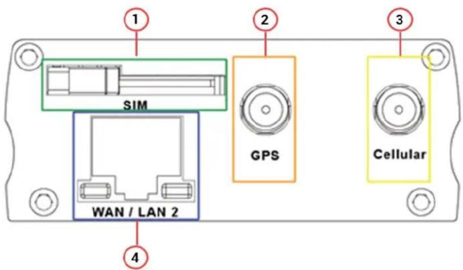
text_image
1 SIM 2 GPS 3 WAN / LAN 2 4 CellularFigure 3-3: Router WAN Panel
| 1 Mini SIM slot (2FF) | |
| 2 | GPS/Diversity SMA Antenna Connector: Female (GPS only on LTE version) |
| 3 Cellular SMA Antenna Connector: Female | |
| 4 | Ethernet Port. Can switch from WAN to LANSupports PoE (Power over Ethernet). PoE wired Ethernet LANS allow the electrical current necessary for the operation to be carried by the data cable rather than carried by power cords, thus removing the need for an external power supply. |
3.5 LED Status Indicators
The E220 operation status is indicated by six LEDs on the top panel as shown in the figure and table below.
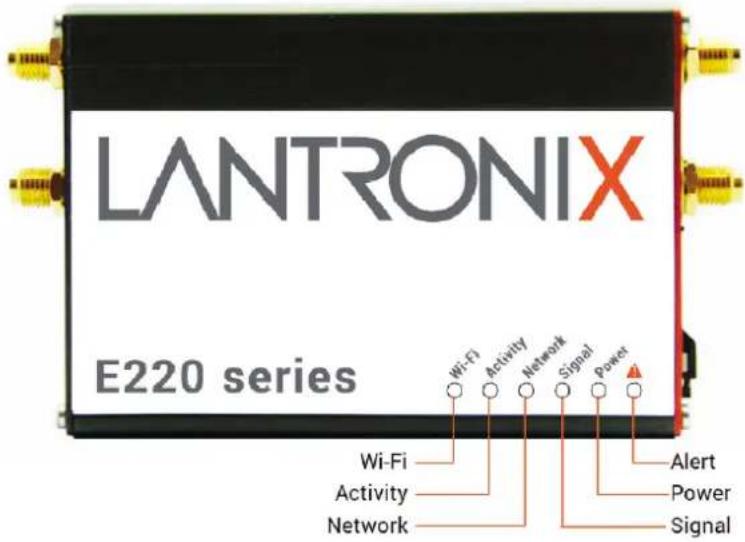
text_image
LANTRONIX E220 series Wi-Fi Activity Network Signal Power Wi-Fi Activity Network Alert Power SignalFigure 3-4: Router Top Panel LEDs
| Name | Color and Status | Description |
| WI-FI | OFF | Wi-Fi network is inactive |
| Blue Flashing | Wi-Fi network connection traffic | |
| Blue ON | Wi-Fi network is up and activate | |
| Activity | OFF | Cellular data service is not connected |
| Amber ON | Cellular data service is connected | |
| Network | OFF | Device is not registered on a cellular network |
| Amber Flashing | Registered on roaming cellular network | |
| Amber ON | Registered on home cellular network | |
| Signal | OFF | No signal (CSQ=0 to 5, 97, 98, 99) |
| Amber Flashing | Weak signal (CSQ >6 to 12) | |
| Amber ON | Strong signal (CSQ ≥ 12) | |
| Power | OFF | Power off |
| Green ON | Power on | |
Alert | OFF | No alert, device is running smoothly |
| Red Flashing | Cellular Module reboot, Linux Kernel booting | |
| Red ON | Hardware fault |
Table 3-3: LED States
4 Installation
4.1 Package Contents
• E220 Series Cellular Router
• E220 Series Quick Start Guide
4.2 User Supplied Items
• SIM card (activated by mobile network operator)
• Power supply and adapters
- Wi-Fi antenna
- Cellular/GPS antenna
- Ethernet CAT5 cable to connect the router to the network
- DIN rail clip
4.3 Accessories
Lantronix accessories for use with the E220 series router are listed in the following table according to part number and application.
Lantronix accessories are available individually or as accessory bundles. To order Lantronix accessories, go to https://www.lantronix.com/about-us/contact/.
- Note: Additional accessories for certain geographic locations are available. Please contact your regional Lantronix Sales office for details.
| Item Description | |
| Power Supply/Cable/Adapters | |
| KDC22 | POWER CABLE, 2-PIN MICRO-FIT 3.0 (M) TO STRIPPED WIRE WITH 2.5 A FUSED, 1-M LONG CABLE |
| P22E0 | POWER SUPPLY, 2-PIN MICROFIT 1.2 A POWER ADAPTER WITH EURO PLUG 2-PIN - EUROPE |
| P22E2 | POWER SUPPLY, 2-PIN MICROFIT 1.2 A POWER ADAPTER WITH NEMA 2-PIN PLUG - AMERICA |
| P22E3 | POWER SUPPLY, 2-PIN MICROFIT 1.2 A POWER ADAPTER WITH AS3112 3-PIN PLUG - AUSTRALIA / NZ |
| P22E4 | POWER SUPPLY, 2-PIN MICROFIT 1.2 A POWER ADAPTER WITH BS1363 3-PIN PLUG - UK |
| Wi-Fi Antenna | |
| A24C0 | 2.4/5.8GHZ WLAN ANTENNA, SMA MALE REVERSE. LIMITED SUPPLY. |
| A21H0 | DUAL-BAND 2.4/5.8GHZ DIPOLE ANTENNA, HINGED, RP-SMA (M) |
| Cellular / GPS Antenna | |
| A31M0 | SINGLE ANTENNA, LTE REMOTE, ADHESIVE, 3-METER RG174 COAX, SMA MALE |
| A31H0 | SINGLE ANTENNA, LTE REMOTE, ADHESIVE, 3-METER COAX, SMA MALE |
| A14M0 | TWO IN ONE LTE + GNSS, 2*3-METER RG174 CABLE WITH 3*SMA MALE, ADHESIVE MOUNT |
| A14H0 | TWO IN ONE LTE + GNSS, 2*3-METER RG174 CABLE WITH 3*SMA MALE, ADHESIVE MOUNT |
| A22H0 | ULTRA-WIDE-BAND 698-960 / 1575.42 / 1710-2700MHZ L-SHAPED ANTENNA, HINGED, SMA (M) |
| Miscellaneous | |
| BR351 | MOUNTING HARDWARE L-SHAPE DIN RAIL CLIP, |
Table 4-1: Lantronix Accessories
4.4 Preparing to Install
Before installation, please gather the router, documentation, and user-supplied items. Refer to the following list for details:
• One or two activated SIM cards, provided by your mobile network operator
- Ethernet CAT5 cable for LAN network connection, if needed
• Wi-Fi and cellular antennas
• Power supply, cable, and adapters
• Personal computer (see below)
See Accessories for compatible Lantronix cables, adapters, and antennas.
Ensure that your computer is equipped with the following:
- Ethernet port or Wi-Fi connectivity and Internet service
- Web browser such as Internet Explorer 10+ or Google Chrome 30+, Mozilla Firefox 20+ or Apple Safari 4+ to access the Lantronix Web Admin Console
- DHCP client enabled on the computer to obtain a valid IP Address from the router.
4.4.1 Enabling DHCP on Your Personal Computer
To enable DHCP on Windows 8 or 10:
- To access the active network, go to Start > Control Panel > Network and Internet > Network and Sharing Center. Click the active network connection. The Network Connection Status dialog box appears.
- From the Network Connection Status dialog, click Properties > select Internet Protocol Version 4 (TCP/IPv4) and click Properties to display the Internet Protocol Version 4 (TCP/IPv4) Properties dialog box.
- On the General tab, select following options:
- Obtain an IP address automatically
- Obtain DNS server address automatically
To enable DHCP on Mac OS:
- Launch System Preferences, then choose Network.
- Select Ethernet from the adapters list on the left.
- Set the Configure IPv4 drop-down to Using DHCP
4.5 Connecting the E220 Router
The steps for connecting the router are:
- Insert the SIM card.
- Connect the cellular and Wi-Fi antennas.
- Connect the AC power.
- Connect the router to a computer.
- Run Quick Setup to configure network settings.
4.5.1 Insert the SIM Card
Insert the SIM card in the router as shown below.

text_image
LANTRONIX E220 series SIM Slot Latch SIM CardFigure 4-1: Inserting the SIM Card in the Router
4.5.2 Connect the Antennas
The table shows the cellular/GPS main and auxiliary antenna options for the E220 series models.
| Main | Model | Auxiliary | Comment |
| Cellular only | E225 Lite N/A | ||
| E224 Lite | Cellular only | Please ensure that the antenna used is suitable for the cellular frequencies in use, for both main and auxiliary connectors | |
| E225 GPS only | |||
| E224 E228 | 2-mode GPS and cellular | Please ensure that the antenna used is suitable for the cellular frequencies in use, for both main and auxiliary connectors |
Table 4-2: E220 Series Main and Auxiliary Antennas
To connect the Wi-Fi/cellular/GPS antenna:
- Connect the cellular antenna to the main connector of the E220 series device as shown in the figure below.
- Use your fingers to securely tighten (clockwise direction) the antenna connector to the connector on the base unit.
- If the Lantronix Router package includes dual antennas; connect the Diversity Antenna to the Diversity Connector.
Note:
Dual antenna provides RF diversification, which allows for improved signal strength and thus better performance for both Wi-Fi and cellular,
Certain circumstances and environments may require the use of a specific type of antenna or one mounted in a different location. Lantronix has many antenna options to choose from, please contact Lantronix Technical Support at http://www.lantronix.com/support.
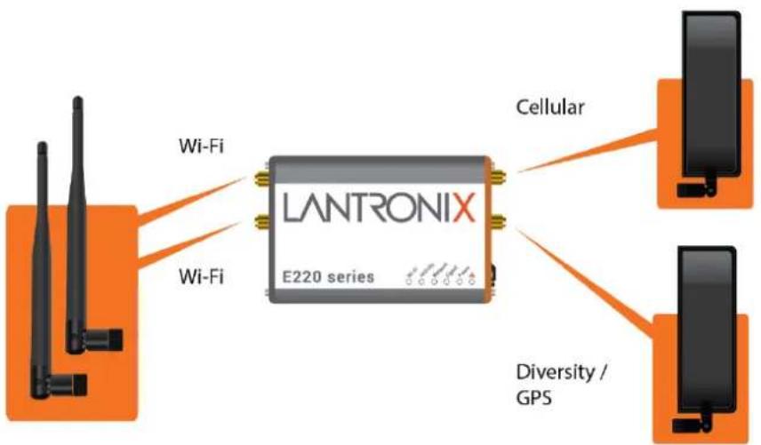
flowchart
graph LR
    A["Wi-Fi"] --> B["LANTRONIX E220 series"]
    C["Wi-Fi"] --> B
    B --> D["Cellular"]
    B --> E["Diversity / GPS"]
Figure 4-2: E220 Series Wi-Fi and Cellular Antenna Connections
4.5.3 Connect the AC Power
To connect the AC power:
- Connect the AC power to the DC in connector, then connect the Micro-Fit connector to the power input, located on the LAN-side panel of the Lantronix Router.
- Plug the AC cord into a standard AC receptacle as shown below.
The power LED will light when power is applied.

natural_image
Illustration of a wireless network device connected to an electrical outlet, showing cable and socket (no text or symbols)Figure 4-3: Connecting the AC Power Connector
4.5.3.1 Power over Ethernet
An alternate option is to power the Lantronix Router over Ethernet port as the WAN port supports Power over Ethernet (PoE).
NOTE: Please refer to the Appendix for Power over Ethernet connections example.
4.5.4 Connect the Router to a Computer
Connect the router to your computer using the router's Wi-Fi access point or an Ethernet cable and log in to the Web Admin page to verify the LAN connection.
To connect via Wi-Fi:
- On the PC, connect to the router's Wi-Fi access point. The table below shows the default wireless access point SSID.
| Parameter Details | |
| SSID | Lantronix E21X - for E210 series devicesLantronix E22X - for E220 series devices |
| WPA/WPA2 TKIP Key | W1rele$$ |
- Open the browser to 192.168.1.1. The Web Admin log in page is displayed.

text_image
LANTRONIX CONNECT SMART. DO MORE. Lantronix Authorization Required Please enter your username and password. admin Login ResetFigure 4-4: Web Admin Login Page
- Log in to the Web Admin console. If the installed ePack firmware is version 2.4.4 and higher, the default factory passwords are:
| User Default Password | |
| admin admin | |
| root L@ntr0n1x |
For password change requirements and for older firmware versions, please see Default Configuration for Web Admin Page. We recommend that you set a unique, strong password for the router and store the password in a secure location.
- Next, you are ready to configure the network settings from the Quick Setup page.
To connect via Ethernet:
- Connect an Ethernet cable between the LAN port on the front panel of the router and the Ethernet port on the computer.
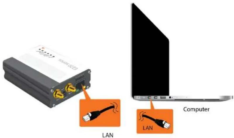
text_image
LAN LAN ComputerFigure 4-5: Router to Computer LAN Connection
- Open the browser to 192.168.1.1. The Web Admin log in page is displayed.

text_image
LANTRONIX CONNECT SMART. DO MORE. Lantronix Authorization Required Please enter your username and password. admin ...... Login ResetFigure 4-6: Web Admin Login Page
- Log in to the Web Admin console. If the installed ePack firmware is version 2.4.4 and higher, the default factory passwords are:
| User Default Password | |
| admin admin | |
| root L@ntr0n1x |
For password change requirements and for older firmware versions, please see Default Configuration for Web Admin Page. We recommend that you set a unique, strong password for the router and store the password in a secure location.
- Next, you are ready to configure the network settings from the Quick Setup page.
4.5.5 Quick Setup
Quick Setup network configuration helps get the IP network port up and running so that you can configure other router settings. To skip the Quick Setup and directly configure the network settings including advanced settings, go to the Network tab.
For details on software configuration, please refer to the Lantronix ePack User Guide for E210 and E220 Devices.
To run quick setup:
- Log in to the Web Admin page and click Quick Setup.
The Quick Setup > Network Setup page is displayed. Basic network parameters for LAN, WAN, Cellular, and Wireless LAN can be configured from the Network Setup page.
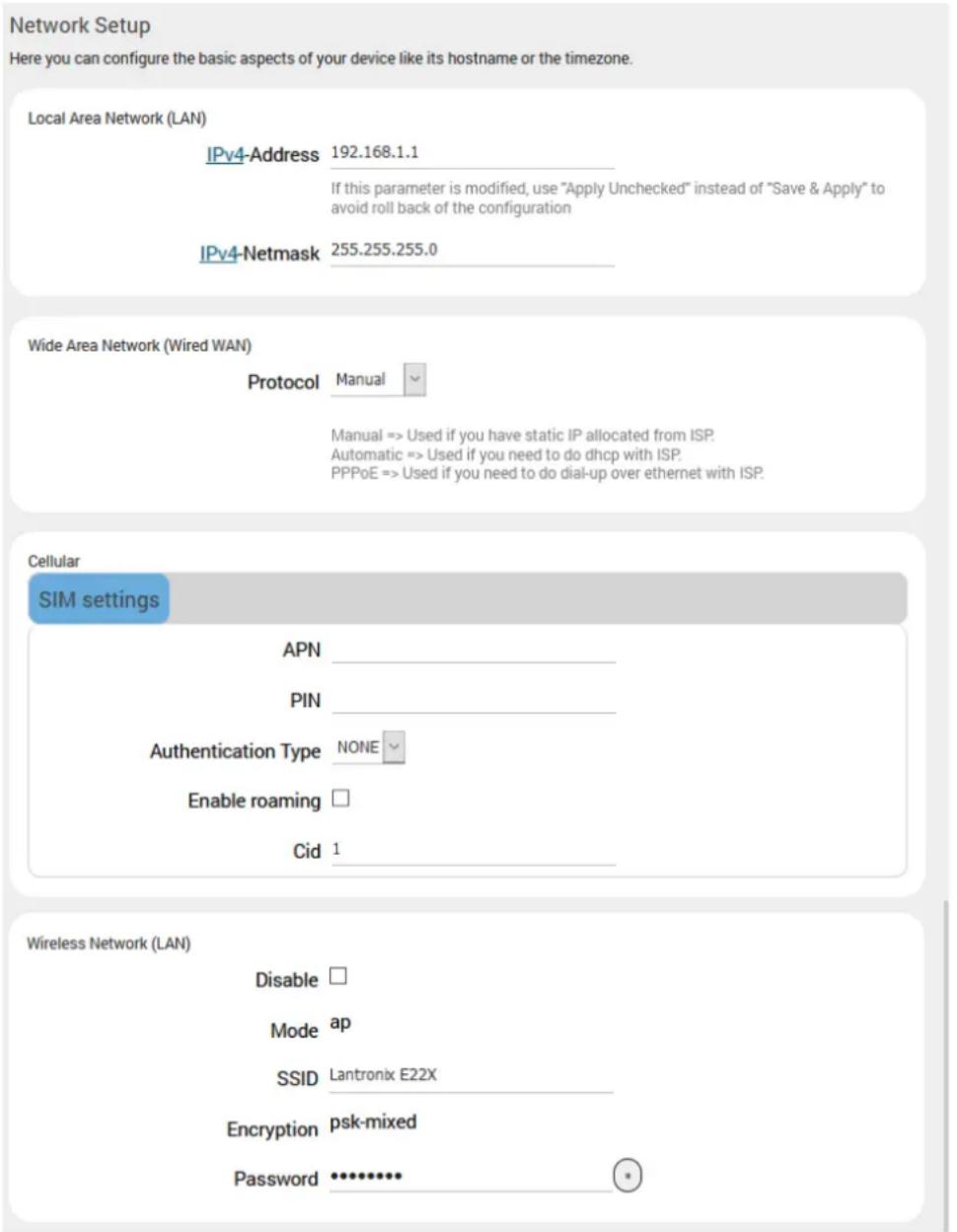
text_image
Network Setup Here you can configure the basic aspects of your device like its hostname or the timezone. Local Area Network (LAN) IPv4-Address 192.168.1.1 If this parameter is modified, use "Apply Unchecked" instead of "Save & Apply" to avoid roll back of the configuration IPv4-Netmask 255.255.255.0 Wide Area Network (Wired WAN) Protocol Manual Manual => Used if you have static IP allocated from ISP. Automatic => Used if you need to do dhcp with ISP. PPPoE => Used if you need to do dial-up over ethernet with ISP. Cellular SIM settings APN ____ PIN ____ Authentication Type NONE Enable roaming □ Cid 1 ____ Wireless Network (LAN) Disable □ Mode ap SSID Lantronix E22X Encryption psk-mixed Password •••••••••• •Figure 4-7: Quick Setup
- Modify the LAN, WAN, Cellular, and Wi-Fi network settings as necessary. See Default Interface Configuration for details of default connection settings.
- Click Save & Apply to store the configuration.
Notes:
- In Cellular, all fields such as APN depend on SIM cards provider/cellular network operator, enquire with them for authentication credentials if needed.
-
After storing the network configuration, the cellular connection should be established within one minute, provided there is adequate signal reception (if the default setting is used.
-
To see the status of the network connections, click Status in the main menu and view the Overview page.
4.5.6 Default Configuration
All usernames and passwords are case sensitive.
4.5.6.1 Default Configuration for Web Admin Page
If the installed ePack firmware is version 2.4.4 and higher, the default factory passwords are:
| User Default Password | |
| admin admin | |
| root L@ntr0n1x |
Table 4-3: Default Web Admin Page Credentials
Note
- ePack firmware versions 2.4.4 and above require you to change the factory default passwords before any other router configuration can be done. Both the admin and root passwords must be changed.
If the installed ePack firmware is older than version 2.4.4, the default factory passwords are:
| User Default Password | |
| admin admin | |
| root M@estroW1rele$$ |
Table 4-4: Default Web Admin Page Credentials
Note: Username and password are both case sensitive.
4.5.6.2 Wireless Access Point SSID
The wireless access point SSID may be configured in the Web Admin console.
| Parameter Details | |
| SSID | Lantronix E21X - for E210 series devicesLantronix E22X - for E220 series devices |
| WPA/WPA2 TKIP Key | W1rele$$ |
Table 4-5: Default Wi-Fi Credentials
4.5.6.3 Default Interface Configuration
| Interface Details | |
| WAN (Ethernet) | Automatic (DHCP client)Priority source of Internet with Cellular backup |
| LAN (Ethernet) Active DHCP with starting IP address192.168.1.100 with pool of 100 clients. | |
| Cellular | No PAP/CHAP authentication |
| Wireless (LAN) | Wi-Fi enabled as access point with SSID"Lantronix E21X" or "Lantronix E22X" |
Table 4-6: Default Interface Configuration
5 Conformity
5.1 Federal Communications Commission (FCC) Compliance Statement
This device complies with part 15 of the FCC Rules. Operation is subject to the following two conditions:
This device may not cause harmful interference.
This device must accept any interference received, including interference that may cause undesired operation.
This device has been tested and found to comply with the limits for a Class B digital pursuant to Part 15 of the FCC Rules. These limits are designed to provide reasonable protection against harmful interference in a residential installation. This equipment generates, uses and can radiate radio frequency energy.
- It not installed and used in accordance with the instructions, may cause harmful interference to radio communications. here is no guarantee that interference will not occur in a particular installation.
-
If this equipment does cause harmful interference to radio or television reception, which can be determined by turning the equipment off and on, the user is encouraged to try to correct the interference by one or more of the following measures:
-
Reorient or relocate the receiving antenna.
○ Increase the separation between the equipment and receiver. - Connect the equipment into an outlet on a circuit different from that to which the receiver is connected.
- Consult the dealer or an experienced radio/TV technician for help.
FCC Caution:
- Changes or modifications not expressly approved by the party responsible for compliance could void the user's authority to operate the equipment.
5.2 FCC RF Exposure Statement
This device complies with FCC radiation exposure limits set forth for an uncontrolled environment. In order to avoid the possibility of exceeding the FCC radio frequency exposure limits, human proximity to the antenna shall not be less than 20cm (8 inches) during normal operation.
5.3 ISED Notice
This device complies with Innovation, Science and Economic Development Canada license-exempt RSS standard(s). Operation is subject to the following two conditions:
(1) this device may not cause interference, and
(2) this device must accept any interference, including interference that may cause undesired operation of the device.
This Class B digital apparatus complies with Canadian ICES-003.
5.4 ISED RF Exposure Information
This device complies with ISED radiation exposure limits set forth for an uncontrolled environment. In order to avoid the possibility of exceeding the ISED radio frequency exposure limits, human proximity to the antenna shall not be less than 20cm (8 inches) during normal operation.
6.1 Pin Power Cable Schematic

text_image
Connection Detail A Color B 1 Red TIN 2 Black TIN 200±40 30±10 10±5 5±678 10±5 A Front slide B -10±5- 3 4 5±1 TIN 1000±20 105±10 9 Note: All materials number be RoHS compliant Part Number: ACC-CA10Figure 6-1: Pin Power Cable Schematic
6.2 Power over Ethernet

flowchart
graph TD
    A["Maestro PSU"] --> B["LANTRONIX E220 series"]
    C["Router / Switch Without POE"] --> B
    D["Router / Switch With POE"] --> B
    E["Router / Switch Without POE"] --> B
    B --> F["End user PSU 9v - 60v"]
    style A fill:#f9f,stroke:#333
    style C fill:#f9f,stroke:#333
    style E fill:#f9f,stroke:#333
Figure 6-2: Power over Ethernet
6.3 RS485 Wiring Diagram
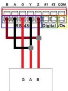
text_image
B A G Y Z #1 #2 COM RS 48 Digital /Os G A B
text_image
B A G Y Z #1 #2 COM RS 48 Digital /Os B A G Y ZFigure 6-3: Half-Duplex (Left), Full-Duplex (Right)
6.4 Certified Antenna
Dipole Wi-Fi antenna:
- 5 dBi high performance antenna
• RP-SMA(M) hinged antenna - RoHS compliant
• Peak gain: 3.8 dBi @2.4 GHz \~ 2.5 GHz
WWAN antenna:
• Dipole 4G swivel blade antenna
• Performance across the LTE frequency bands
• 698-960 / 1710-2170 / 2500-2700 MHz
- Up to 2 dBi gain
- SMA connector
• RoHS compliant product
6.5 Antenna Selection
Selection of Wi-Fi antenna:
• Dipole, Peak Gain < 3.8 dBi @ 2.4 GHz \~ 2.5 GHz
Selection of antenna type:
- Using the same dipole antenna type as certified module & Modem for FCC as above or external antenna with length > 20 cm.