AZ29E09DAC - Washing machine GE - Free user manual and instructions
Find the device manual for free AZ29E09DAC GE in PDF.

User questions about AZ29E09DAC GE
0 question about this device. Answer the ones you know or ask your own.
Ask a new question about this device
Download the instructions for your Washing machine in PDF format for free! Find your manual AZ29E09DAC - GE and take your electronic device back in hand. On this page are published all the documents necessary for the use of your device. AZ29E09DAC by GE.
USER MANUAL AZ29E09DAC GE
natural_image
Close-up of a beige car hood with a GE logo on the grille, showing grille grating and ventilation grille (no text or symbols visible)GE Zoneline packaged terminal air conditioners
2009 contract sales architects and engineers data manual
Power Connection Kits
230/208-Volt Line Cord Connection Units
| Line Cord Kit | Electric Heat BTUH | Electric Heater Watts | Electric Heat Amps | Min. Circuit Protection (Amps) |
| RAK3153 8600/7100 2550/2090 11.6/10.6 15 | ||||
| RAK3203 | 11700/9600 3450/2820 15.5/14.1 20 | |||
| RAK3303 17100/13900 | 5000/4090 223.3/20.3 30 | |||
Electric Heat Amps include electric heater and fan motor current draw. Each Line Cord Kit has an integral Leakage Current Detection and Interruption (LCDII or Arc Fault) Current Interrupter (AFCII) device as required by National Electrical Code (NEC) and Underwriters Laboratories (ULI) for units manufactured after August 1, 2004.
230/208-Volt Sub-Base and Direct Connected Units
| Sub-Base | Direct Connection Kit | Electric Heat BTUH | Electric Heater Watts | Electric Heat Amps | Min. Circuit Protection (Amps) |
| RAK204D15P | RAK4157 8600 | 7100 2550/20 | 90 11.6/10 | 6 15 | |
| RAK204D20P | RAK4207 | 11700/9600 | 3450/2820 | 15.5/14.1 | 20 |
| RAK204D30P | RAK4307 1 | 7100/13900 | 5000/4090 | 22.3/20.3 | 30 |
Electric Heat Amps include electric heater and fan motor current draw. Units connected through sub-base do not require an LCDI or AFCI device since they are not considered to be line-cord connected. Each 230/208-volt sub-base kit consists of sub-base with appropriate receptacle for minimum circuit amperage, chaseway to route power connector from sub-base to chassis, wiring to connect sub-base to building wiring and a short line cord with 9-pin connector to connect to chassis and plug into receptacle in sub-base. Short sub-base line cord may not be used without sub-base. Junction box for 230/208-volt chassis must be purchased separately. RAK4002A for 2900 and 3900 series units, RAK4002B for 5800 series units.
265-Volt Sub-Base and Direct Connected Units
| Sub-Base | Power Connection Kit | Direct Connection Kit | Electric Heat BTUH | Electric Heater Watts | Electric Heat Amps | Min. Circuit Protection (Amps) |
| RAK204E15 | RAK5172 | RAK5157 | 8600 | 2550 | 9.6 | 15 |
| RAK204E20 | RAK5202 | RAK5207 | 11700 | 3450 | 13.0 | 20 |
| RAK204E30 | RAK5302 | RAK5307 | 17000 | 5000 | 18.9 | 30 |
Electric Heat Amps include electric heater and fan motor current draw. 265-volt units are to be permanently connected in compliance with National Electrical Code and local codes and have a factory-installed junction box on the chassis. Each 265-volt sub-base kit consists of sub-base with appropriate receptacle for minimum circuit amperage, chaseway to route power connector from sub-base to chassis and wiring to connect sub-base to building wiring. 265-Volt Power Connection Kit must be ordered separately.
Important
Essential Elements Ordering Overview
230/208-volt line cord connected units — order line cord kit 230/208-volt sub-base connected units — order sub-base and junction box 265-volt units — order sub-base and power connection kit
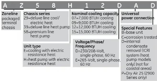
Zoneline® Chassis Nomenclature
The Zoneline chassis is identified by a model number defining the type of unit, cooling capacity, electrical information and optional features included on the unit. When specifying or ordering the Zoneline chassis, the use of this nomenclature will assure receiving the correct unit.
EXAMPLE
text_image
A Z 5 8 H 1 2 D A D Zoneline packaged terminal chassis Chassis series 29=deluxe line cool/ electric heat 39=deluxe line heat pump 58=premium line heat pump Unit type E=cooling with electric resistance heat H=heat pump with electric resistance heat Nominal cooling capacity 07=7,000 BTUH cooling 09=9,000 BTUH cooling 12=12,000 BTUH cooling 15=15,000 BTUH cooling Voltage/Phase/Frequency D=230/208-Volt, single-phase, 60 Hz E=265-Volt, single-phase, 60 Hz Universal power connection Special Features B=base unit C=corrosion treated D=internal condensate removal (ICR) system (heat pump models only (not for coastal areas)) P=Dry Air 25 I2900 Series only)The Zoneline® 2900, 3900 and 5800 Series have incorporated changes suggested by customers, along with enhancements by GE's Technology Team and changes necessary to meet new UL and NEC requirements.
"L" shaped condenser coil.
The "Partial Open Vent Air" feature was a specific request by a customer.
"Heat Sentinel" is an enhancement developed by GE's Technology Team to help lodging professionals welcome their guests with a moderate-temperature room and to help lower cooling costs.
Devices have been added on cord-connected units to protect against injury from unsafe power cords.
See the "Features and Benefits" section for in-depth explanation of these changes and the industry-leading features of GE Zoneline retained from the previous series.
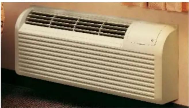
The Deluxe 2900 Series Zoneline models include The "Dry Air 25" models which remove 25% more moisture than other Zoneline models.
natural_image
White air conditioner unit with horizontal ventilation grilles (no visible text or symbols)Deluxe Dry Air 25 Models Cooling With Resistance Heat
- Remove 25% more moisture than other Zoneline models, up to 2.7 additional gallons per day
- Cool and dry air in less time than standard Zoneline models
- Heat pipe is a separate sealed refrigerant system
— No mechanical parts — No special maintenance required
• Helps maintain lower relative humidity in rooms - Maintains comfort at slightly higher room temperatures
— Reduces operating costs — Provides comfort without overcooling
• Corrosion treatment is standard
• Excellent choice for humid climates
• Available in 7000, 9000 and 12000 BTU sizes
The Dry Air 25 system, a heat pipe, is a hermetically sealed heat transfer surface installed in a "saddlebag" configuration around the indoor (evaporator) coil of the Zoneline unit. This coil arrangement will transfer heat from the front coil of the saddlebag to the rear coil without power consumption.
This assembly uses R-22 as the refrigerant and is not connected to the regular Zoneline refrigerant circuit.
As warm, humid air is pulled through the pre-cool (front) section of the heat pipe, the heat removed from the air is absorbed by the refrigerant, causing the refrigerant to change to a gas and flow to the re-heat (rear) section of the heat pipe. The air leaving the pre-cool section of the heat pipe is cooler and at a higher relative humidity level than the room air. The pre-cooled air is further cooled as it passes through the evaporator; consequently, the relative humidity increases allowing the evaporator coil to remove more moisture.
When the cold air from the evaporator comes in contact with the re-heat section of the heat pipe, the heat that was removed by the pre-cool section is added back to the air and the refrigerant in the heat pipe condenses and flows back to the indoor coil. The air discharged into the room by this process is much drier, creating a more comfortable room condition.
The Dry Air 25 models center around GE's exclusive use of the patented Dinh® Dehumidifier Heat Pipe from Heat Pipe Technology, Inc. This innovative NASA spin-off technology enables Dry Air 25 to remove 25% more moisture from the air than other leading manufacturers' packaged terminal air conditioners. This helps maintain room comfort at a higher room temperature, reducing operating costs.
The Dry Air 25 keeps a room cool and dry, and this is the most important benefit when it comes to the occupant of the room—hotel guests, apartment residents, students. In a hot, humid climate, getting away from the humidity is just as important as getting away from the heat, and the Dry Air 25 is the perfect solution. The dehumidification of the Dry Air 25 has been verified by the same ARI test conditions that standard units are rated under.
Table of Contents
Front Cover 1
Mini Specs 2900, 3900 and 5800 Series 2
Mini Specs Power Connection Kits and Nomenclature 3
The 2900/3900/5800 and Dry 25 4
Table of Contents 5
Introduction 6
The Zoneline System 7
Features and Benefits
Features Table 8
Features and Benefits 9–11
Auxiliary Control Switches 12-13
Central Desk Control 14
Remote Thermostat Control 15-17
Heat Pumps and Energy Savings 18–19
Installation and Dimensions
Application Comments 20
Case Dimensions 21
Wall Case/Sub-Base Installation 22-33
Condensate Disposal Systems 34–36
Ducted Installations 37-39
Exterior Grilles 40-41
Product Data
Electrical Connection 42
Essential Elements Ordering Overview 43
Maximum Connected Load 44
Cooling/Heat Pump Performance Data 45
Latent System Capacity 46
Normal Yearly Operating Data 47
Schematics 48-51
Product Specifications
Suggested Bid Form Specifications 52-53
Zoneline Chassis Nomenclature/Receptacles/Sub-Bases 54
Specifications 55
Complete Accessory List 56
General Installation Suggestions 57-58
Warranty 58
Alphabetical Index 59
Back Cover 60
Important Notice
Equipment used as a primary source for heating or cooling is an integral part of the building in which it is installed. Proper application is essential for satisfactory performance over a wide range of operating conditions. It is strongly recommended that a professional engineer determine proper application.
If the unit is a replacement unit, its specifications and performance may differ from those of the unit it is replacing. For that reason, we again strongly recommend that a professional engineer determine proper application.
Introduction
This manual is designed to provide product, performance and application information to our customers and their architects and engineers for use in selection and design of a zonal comfort control system utilizing GE Zoneline® Packaged Terminal Air Conditioners (PTAC) and Packaged Terminal Heat Pumps (PTHP). GE Zoneline PTACs and PTHPs are self-contained units designed for through-the-wall installations in hotels, motels, apartments, hospitals, nursing homes, add-on rooms and many other installations.
Zoneline units provide individual room or zone control in both cooling and heating operation. There is a model for practically every application, ranging in cooling capacity from 7,100 to 14,750 BTUH and heating capacity from 6,400 to 13,800 BTUH in heat pump operation. See pages 42 and 54 for resistance heaters available.
Zoneline offers a two-tier lineup: the Deluxe Line and the Premium Line. The Deluxe Line consists of the 2900 Series with electric resistance heat, the 2900 Series Dry Air 25 Models with enhanced dehumidification for hot and humid climates and the 3900 Series heat pump. The 3900 Series heat pump features reverse cycle defrost and simultaneous supplemental resistance heat, when needed, to maintain room comfort.
The Premium Line features the 5800 Series heat pump with reverse cycle defrost and supplemental resistance heat, when needed, to maintain room comfort, plus tactile touch controls with digital display and standard corrosion protection.
Deluxe Line Standard Features:
- Digital Controls
—LED Temperature Display
—Easy Temperature Selection
—Tactile Touch Pad
• Universal Heaters - 2 Fan Motors
- Heat Sentinel
- "L" Coil Design Condenser
• 3-Position Vent Door - Freeze Sentinel ^TM
- Indoor Coil Frost Control
• Central Desk Control Interface - Remote Thermostat Control Interface
- Random Restart
• Electronic Temperature Limiting - "Smart Fan" Fan Cycle/Continuous Control
- Transfer Fan Interface
- Reverse Cycle Defrost and Simultaneous Supplemental Resistance Heat on Heat Pumps
- Quick Heat Recovery
Deluxe Line Optional Features:
• Corrosion Protection
- Internal Condensate Removal (on 3900 Series Heat Pump without Corrosion Protection)
Premium Line Standard Features:
All the Standard Features of the Deluxe Line Plus:
- Two-fan-motor system with Indoor Cross-Flow Blower for quieter operation
- Unit Diagnostics
• Standard Corrosion Protection Treatment
Premium Line Optional Features:
- Internal Condensate Removal (not for use in seacoast or corrosive areas)
Advantages of the GE Zoneline System:
- Flexible Application
— May be installed from flush to finished floor to 3" from the ceiling
— 7,100 to 14,700 BTUH units in same physical size
— Deluxe 2900 and 3900 Series may be ducted to condition more than one room
— Compatible with Class 2 remote thermostat control
— Compatible with 2-wire CDC or many Energy Management Systems
• Economical Installation
— No ductwork necessary
— No mechanical equipment rooms or pipes required for heating/cooling units
— Replacement units fit existing 42"-wide by 16"-high wall cases
- Quiet Operation
— Indoor double cut-off scroll: two-fan-motor 2900 and 3900 Series units
— Indoor cross-flow blower: 2-fan-motor 5800 Series units
• Energy-Saving Operation
— Units in unoccupied areas may be turned off
— Designed for efficient cooling operation — EERs from 10.0 to 13.0
— Efficient heat pump units — COPs from 3.2 to 3.7
— Extended heat pump operation without sacrificing room comfort
- Ease of Maintenance
— Permanently lubricated fan motors
— Upfront lift-out interchangeable filters
— Air Discharge area is easily accessed for cleaning
— Slide-out chassis for easy access for cleaning or if service is required
- Reverse Cycle Heat Pump Operation
Both the 3900 and the 5800 Series heat pumps utilize the unique GE PTAC heat pump operation to ensure a comfortable room. The logic used by the units is the same logic used by central system heat pumps to provide greater savings.
The Zoneline System
The typical Zoneline installation consists of the wall case (or sleeve), chassis, power cord and exterior grille. Some installations may use a sub-base for support of the unit or for ease of electrical connections. Each of the components should be the standard products offered by GE or, in the case of the exterior grille, approved by GE Applications Engineering. Use of components not specifically designed or approved for use with the Zoneline unit can result in unsatisfactory operation and can be the cause of failure not covered by the warranty.
Components of the Zoneline System
Typical Installation (Deluxe Series shown)

text_image
Room Cabinet Chassis Wall Case RAB71A (Steel-Insulated) RAB77A4 (SMC — Molded) Wall Case Options (See page 22) RAG67 (shown) Grille Options (See page 40) Power Connection Kit (required on all units) Line Cord Kit shown See pages 42-43 Power Supply CordOptional Accessories of the Zoneline System

text_image
Chaseway RAK204D20P Sub-Base (shown)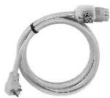
natural_image
Coiled electrical cable with two connectors and a terminal connector (no text or symbols visible)Power Supply Cord (included with 208V/230V sub-bases)

natural_image
Exterior view of a RAK6052 Duct Adapter (For Deluxe Series) with no visible text or symbols on the diagram itself.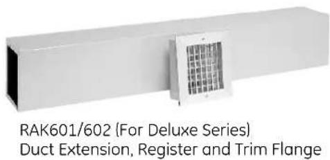
text_image
RAK601/602 (For Deluxe Series) Duct Extension, Register and Trim FlangeSee pages 22 and 32 for information on electrical sub-bases and chaseway. See pages 37-39 for information on ducted installations.
Zoneline® Features
AZ AZ AZ
2900 3900 5800
| Enhanced Dehumidification — Dry Air 25 Optional N/A N/A | |||
| Cooling EER Range (230 Volts/265 Volts) 10.2 - 12.7 10.0 - 12.7 10.3 - 13.0 | |||
| Heating COP Range (230 Volts/265 Volts) | N/A | 3.2 - 3.6 | 3.2 - 3.7 |
| Heat Source — Electric Resistance Heat | Standard | — | — |
| Heat Source — Heat Pump With Selectable Full-Time or On-Demand Simultaneous/Supplemental Resistance Heat | — | Standard | Standard |
| Staged Heating | — | 3-Stage | 3-Stage |
| Universal Heater — UPC* | Standard | Standard | Standard |
| Unit Controls | Touch Pad | Touch Pad | Touch Pad |
| Electronic Temperature Selection(Slews Up & Down) with Digital Display | Standard | Standard | Standard |
| Unit Diagnostics | — | — | Standard |
| Highly Featured Microprocessor Controls | Standard | Standard | Standard-Plus |
| Electric Resistance Heat Lock-Out (above 46°F) | — | Standard | Standard |
| Automatic Emergency Heat | — | Standard | Standard |
| Heat Pump Defrost System | — | Reverse Cycle | Reverse Cycle |
| High-Temperature Operation Protection | — | Standard | Standard |
| Quick Heat Recovery | — | Standard | Standard |
| Temperature Boost | Selectable | Selectable | |
| Service Indicator | — | — Temp Display Blinks | |
| Fan Motors — Permanently Lubricated | 2 | 2 | 2 |
| 2-Speed Outdoor Fan | Standard | Standard | Standard |
| Indoor Fan Speed Selections — HIGH/LOW/AUTO | Standard | Standard | Standard |
| Fan Only Setting — HIGH/LOW | Standard | Standard | Standard |
| Fan Cycle Switch | "Smart Fan" | "Smart Fan" | "Smart Fan" |
| Constant-Run Fan | Selectable | Selectable | Selectable |
| Rotary Compressor | Standard | Standard | Standard |
| Automatic Compressor Restart Delay | Standard | Standard | Standard |
| Freeze SentinelTM | Standard | Standard | Standard |
| Heat Sentinel | Standard | Standard | Standard |
| Indoor Coil Frost Control | Standard | Standard | Standard |
| Transfer Fan Connections | Standard | Standard | Standard |
| 7-Step Electronic Temperature Limiting | Standard | Standard | Standard |
| Remote Control Capability with Wall-Mounted Thermostat | Standard | Standard | Standard |
| Central Desk Control Capability | Standard | Standard | Standard |
| Energy Management System Interface with Load-Shedding Option | Standard | Standard | Standard |
| Reversible Indoor Air Louvers 40°/50° | Standard | Standard | Standard |
| Up-Front Filters | Standard | Standard | Standard |
| Easy-Clean Air Discharge Area | Standard | Standard | — |
| Concealed Manual Vent Control | Standard | Standard | Standard |
| Ducted Installation Capability | RAK6052 | RAK6052 | — |
| Corrosion Protection (Standard on Dry Air 25) | Optional | Optional | Standard |
| Internal Condensate Removal (ICR) (Factory-Installed Option.Cannot be used in Corrosion Areas.) | N/A Optional | Optional | |
*UPC — Universal Power Cord Connection (see pages 42 and 54).
265-volt units must be connected in a manner to meet National Electrical Code and all local codes.
Features and Benefits
Standard Physical Dimensions
GE has maintained the same dimensions since 1961 — 42" wide × 16" high × 13-3/4" deep
Replacement of older units is made easy.
Weather-Protected Electrical Components
Vital electrical components are protected from the weather by locating them on the indoor side of the weather barrier.
Weather-Resistant "Superseal"
Properly installed unit in undistorted case keeps air leakage to a minimum.
7 CFM air infiltration with 25 MPH wind on non-ICR units — 10 CFM on units with ICR.
Industry specification is 19 CFM of air infiltration.
Heater Sizes to Meet Room Requirements
All units are equipped with a universal heater — the resistance heat output is determined by power connection kit.
230/208-volt — Line-Cord Connected Units — 2.55/2.09 KW with RAK3153 — 15-amp circuit; 3.45/2.82 KW with RAK3203 — 20-amp circuit; 5.0/4.09 KW with RAK3303 — 30-amp circuit.
230/208-volt - Sub-Base Connected Units — 2.55/2.09 KW with RAK204D15P — 15-amp circuit; 3.45/2.82 KW with RAK204D20P — 20-amp circuit; 5.0/4.09 KW with RAK204D30P — 30-amp circuit.
265-volt — 2.55 KW with RAK5172 — 15-amp circuit; 3.45 KW with RAK5202 — 20-amp circuit; 5.0 KW with RAK5302 — 30-amp circuit.
Unit Controls
2900 and 3900 Series — touch pad controls for temperature and operation selection.
5800 Series — touch pad controls with digital readout of temperature set point.
Highly Featured Microprocessor Controls
Microprocessor controls are programmed to interface with the temperature sensors to maximize comfort conditions for the room occupant and provide outstanding features.
Thermistors are used to sense small changes in temperature to give excellent room control and allow the microprocessor to monitor and react to changing conditions.
Electric Resistance Heat Lock-Out
To maximize the savings of the heat pump operation, the Zoneline heat pumps do not utilize the resistance heater when the outdoor temperature is above 46^ F during normal operation. The resistance heat is used in the Quick Heat Recovery feature.
Automatic Emergency Heat
Automatically uses electric resistance heat if the heat pump output is not sufficient to maintain selected room temperature.
Reverse Cycle Heat Pump Defrost System
Standard on all Zoneline 3900 and 5800 Series heat pumps.
Enables heat pump to operate at lower temperatures when other systems switch to more expensive electric resistance heat.
See pages 18 and 19 for discussion of heat pump operation and defrost systems.
High-Temperature Heat Pump Operation Protection
Automatically protects the compressor if heat pump is operated with high outdoor temperatures.
Power to the outdoor fan is turned off if the indoor coil gets too hot during heat pump operation to prevent damage to the compressor.
Quick Heat Recovery – Heat Pump Units
When the unit operation is changed from STOP or COOL to HEAT, the electric resistance heaters are used to warm the room to the thermostat set point. This provides faster room temperature increase for greater guest comfort.
Unit Diagnostics
The 5800 Series has a dip switch that activates each of the various components of the unit to operate briefly. This enables the technician to determine if individual components are functioning properly.
Service Indicator
On the 5800 Series, if the microprocessor detects a compressor malfunction, the digital temperature display will blink. If the malfunction occurs during cooling operation, the indoor fan will continue to operate. If the compressor malfunctions in heating mode, the unit will automatically switch to resistance heat to maintain room temperature set point. GE Service should be called to check the Zoneline unit.
Fan Motors – Permanently Lubricated
All units have two fan motors for quiet operation and maximum operating efficiency.
Motors are permanently lubricated to reduce maintenance and totally enclosed to keep dirt and water out of the motor windings.
2-Speed Outdoor Fan
The unit automatically selects the most efficient speed for the outdoor fan. The operating sound level is lower when the outdoor fan can operate in low speed yet there are situations where it must operate in high speed. The unit changes the fan speed automatically.
Indoor Fan Speed Selections – HIGH/LOW
Unit may be operated in HIGH HEAT or LOW HEAT or HIGH COOL or LOW COOL.
Features and Benefits
Fan-Only Setting - HIGH/LOW
The unit provides the option of selecting either HIGH or LOW speed for Fan-Only operation.
Fan-Cycle Switch - "SmartFan"
Unique "SmartFan" allows unit to operate fan continuously in cooling operation and fan cycle in heating to provide better guest comfort. Eliminates complaint of cold air draft during heating operation.
Eliminates need of changing fan-cycle switch seasonally.
"SmartFan" settings are controlled by two dip switches on auxiliary control panel.
Compressor Random Restart
In the event of a power failure, all compressors attempting to restart immediately when power is restored can result in a power surge that can cause another power interruption.
The microprocessors in the Zoneline ^® units have a random restart logic system that prevents all units from starting at the same time.
Rotary Compressor
Smoother operation for quiet, dependable service. GE has used rotary compressors since 1961.
Compressor Restart Delay
Zoneline units are designed to provide a minimum of three minutes of compressor off time to allow refrigerant pressures to equalize before restarting to prevent compressor damage.
Zoneline units are also designed to provide a minimum of three minutes of compressor run time to prevent room occupant disturbance due to short-cycling of the air conditioner.
Freeze Sentinel
Detects low room temperature and turns on heater to help protect against damage caused by freezing room temperature.
Heater turns on at 41°F and warms indoor thermistor temperature to 46°F and shuts off.
Freeze Sentinel may be turned off by dip switch on auxiliary control.
Heat Sentinel
The property owner may choose to activate the Heat Sentinel feature on the Zoneline unit. If the Heat Sentinel is activated and room temperature reaches 85°F while the unit is in the "STOP" setting, the unit will automatically start in air conditioning operation and will shut off when the room temperature reaches 80°F. This will help dehumidify the air and lower high temperatures so the guest will not be entering an extremely hot room.
Indoor Coil Frost Control

natural_image
Close-up of interlocking metal pipes and cables (no visible text or symbols)Prevents indoor coil from freezing and causing complaints due to lack of cooling. Frost can form on the indoor coil when the unit is operated in cooling when outdoor temperatures are low. The unit automatically shuts the compressor off until the indoor coil temperature warms to the point where frosting will no longer occur.
Transfer Fan Interface
24 VAC terminals are provided to operate a relay to control a fan mounted in a wall to move conditioned air into another space. The electrical power for the operation of the transfer fan itself is not provided by the Zoneline unit. Transfer fans and their controlling relays are field supplied.
Electronic Temperature Limiting
Seven independent programmable heating temperature limits and seven independent programmable cooling temperature limits.
| Heating Temperature Limits | Highest Heat | ||||||
| 65 70 | 72 74 | 76 78 80 | 85 | ||||
| Lowest Cool | Cooling Temperature Limits | ||||||
| 60 64 | 66 68 | 70 72 74 | 76 | ||||
Limits are set by dip switches on auxiliary control panel.
Remote Control Capability with Wall-Mounted Thermostat
See pages 15–17.
Central Desk Control Capability
See page 14.
Energy Management System Interface with Load-Shedding Option
All units have a switch on the auxiliary control panel to allow the indoor fan to continue operating if the unit is connected to an energy management system that shuts off compressor or heater operation. By allowing the indoor fan to run when the heater or compressor is shut off by the energy management system, the guest is less likely to realize the operation of the unit has been altered. This helps reduce peak energy demand loads without disturbing the room occupant.
Reversible Indoor Air Louvers
Allows air to be directed into room at 40^ or 50^ angle to provide better air distribution.
Angle is changed by removing room front and screws holding louver in place, and rotating louver section.
Features and Benefits

natural_image
Person placing a white sheet of paper on an air conditioner cover (no visible text or symbols)Up-Front Air Filters
Two interchangeable up-front filters, easy to remove and reinstall, may be cleaned without opening or removing the room front.
Clean filters by brushing, vacuuming or back-flushing under faucet or shower head.
Easy-Clean Air Discharge Area
2900 and 3900 Series units have an out-of-sight vertical protective screen over the indoor fan. This allows easy cleaning of air discharge area by simply removing room front and wiping clean.
There is no screen directly below discharge louver to trap unsightly dirt and debris where it may be seen by room occupant.
Concealed Manual Vent Control
The 3-position manual vent door control may be closed, partially open or fully open.

natural_image
Close-up of a mechanical switch or lever mechanism with no visible text or symbolsVent CFM High Speed
Unit Full Open Partial Open
| 7000 | 50 | 40 |
| 9000 | 70 | 45 |
| 12000 | 75 | 45 |
| 15000 | 75 | 45 |
CFM ratings at 230 volts and 265 volts.
Greater amounts of air will be introduced if the room has an exhaust fan.
An open vent door brings unconditioned outdoor air into the room, increasing heating and cooling costs.
Positive vent door closure prevents accidental opening and unwanted air infiltration.
Corrosion Protection (Optional)
2900 and 3900 Series units may be ordered with special protection to better withstand damage from salt air and salt water in seacoast areas.
Corrosion protection is standard on the 5800 Series and on Dry Air 25 models.
Heat pump units with ICR are not available with corrosion protection and should not be installed in seacoast or corrosive environments.
Units installed in corrosive areas should be examined and cleaned more frequently than normal installations.
Internal Condensate Removal (ICR)
See page 34 for a discussion of the Internal Condensate Removal system available on 3900 and 5800 Series heat pumps.
Enhanced Dehumidification
Moisture removal is an important function of an air conditioner. People are more comfortable at higher temperatures when the humidity level is relatively low. Air conditioners operate with less energy consumption when the room temperatures are set higher.
The GE Zoneline 2900 Series with the Dry Air 25 heat pipe application removes 25% more moisture than the base 2900 Series unit.
The GE Zoneline Dry Air 25 chassis is the only PTAC available with the application of the patented Dinh® Dehumidifier Heat Pipe under license from Heat Pipe Technology, Inc.
Customers who are using the Dry Air 25 report a fresher-smelling room as a result of the lower humidity levels, as well as lower operating costs.
Locking Door Kit
RAK8023 — A door with a lock that replaces the standard control cover door to prevent unauthorized changing of control setting is offered as an accessory.
Auxiliary Control Switches
These switches are located behind the room cabinet under the control panel.
2900 and 3900 Series
Switches Description
| Left Switches | |
| (1) ALL I2R Heat pump override —Down — Normal heat pump operationUp — resistance heat only (3900 Series only) | |
| (2) C: FAN Fan control for cooling operation —Down — Fan ContinuousUp — Fan Cycle | |
| (3) H: FAN Fan control for heating operation —Down — Fan CycleUp — Fan Continuous | |
| (4) CLASS 2 Remote Thermostat Mode —Down — Unit ControlUp — Remote Thermostat | |
| (5) LOAD SHED Load Shedding when connected to Central Desk Control System —Down — Fan shuts off with unitUp — Fan under “Smart Fan” settings | |
| (6) FREEZ S Freeze SentinelTM Override —Down — Freeze Sentinel ONUp — Freeze Sentinel OFF | |
| (7) CONST FAN Constant Fan —Down — Fan runs normallyUp — Fan runs when unit is in STOP position | |
| Right Switches | |
| TL1 - TL3 | Cooling temperature limiting (See table at bottom of page) |
| TL4 - TL6 | Heating temperature limiting (See table at bottom of page) |
| (7) | Heat Sentinel switch —Down — Heat Sentinel OFFUp — Heat Sentinel ON |
| (8) | Heat Boost (3900 series only) —Down — Heat Boost OFFUp — Heat Boost ON |
| Auxiliary (2900 and 3900 series) | |
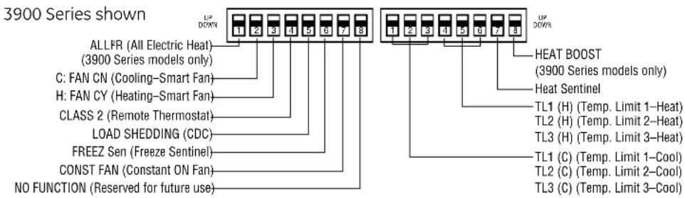
text_image
3900 Series shown ALLFR (All Electric Heat) (3900 Series models only) C: FAN CN (Cooling-Smart Fan) H: FAN CY (Heating-Smart Fan) CLASS 2 (Remote Thermostat) LOAD SHEDDING (CDC) FREEZ Sen (Freeze Sentinel) CONST FAN (Constant ON Fan) NO FUNCTION (Reserved for future use) UP DOWN UP DOWN 1 2 3 4 5 6 7 8 1 2 3 4 5 6 7 8 HEAT BOOST (3900 Series models only) Heat Sentinel TL1 (H) (Temp. Limit 1-Heat) TL2 (H) (Temp. Limit 2-Heat) TL3 (H) (Temp. Limit 3-Heat) TL1 (C) (Temp. Limit 1-Cool) TL2 (C) (Temp. Limit 2-Cool) TL3 (C) (Temp. Limit 3-Cool)Cooling and heating temperature limits are set independently, temperature limiting switches are in factory-set down position, except as noted.
Cooling Temperature Limits
| Switches Up | NONE | 1 | 1,2 | 2 | 2,3 | 1,2,3 | 1,3 | 3 |
| 60 | 64 | 66 | 68 | 70 | 72 | 74 | 76 | |
| Heating Temperature Limits | ||||||||
| Switches Up | 6 | 4,6 | 4,5,6 | 5,6 | 5 | 4,5 | 4 | NONE |
| 65 | 70 | 72 | 74 | 76 | 78 | 80 | 85 | |
Auxiliary Control Switches
These switches are located behind the room cabinet under the control panel.
5800 Series
Switches Description
| Left Switches | |
| (1) ALL I2R Heat pump override —Down — Normal heat pump operationUp — resistance heat only | |
| (2) C: FAN Fan control for cooling operation —Down — Fan ContinuousUp — Fan Cycle | |
| (3) H: FAN Fan control for heating operation —Down — Fan CycleUp — Fan Continuous | |
| (4) CLASS 2 Remote Thermostat Mode —Down — Unit ControlUp — Remote Thermostat | |
| (5) LOAD SHED Load Shedding when connected to Central Desk Control System —Down — Fan shuts off with unitUp — fan under “Smart Fan” settings | |
| (6) FREEZ S Freeze Sentinel Override —Down — Freeze Sentinel ONUp — Freeze Sentinel OFF | |
| (7) CONST FAN Constant Fan —Down — Fan runs normallyUp — fan runs when unit is in STOP position | |
| (8) OCCUPIED Occupancy Sensor Mode —Down — Unit ControlUp — Occupancy Sensor Connected |
Right Switches
| TL1 - TL3 | Cooling temperature limiting (See table at bottom of page) |
| TL4 - TL6 | Heating temperature limiting (See table at bottom of page) |
| (7) | Diagnostics Switch |
| (8) | Heat Sentinel switch —Down — Heat Sentinel OFFUp — Heat Sentinel ON |
| (9) | Heat Boost —Down — Heat Boost OFFUp — Heat Boost ON |
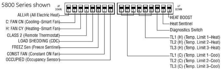
text_image
5800 Series shown ALL(R (All Electric Heat) C: FAN CN (Cooling-Smart Fan) H: FAN CY (Heating-Smart Fan) CLASS 2 (Remote Thermostat) LOAD SHEDDING (CDC) FREEZ Sen (Freeze Sentinel) CONST FAN (Constant ON Fan) OCCUPIED (Occupancy Sensor) UP DOWN 1 2 3 4 5 6 7 8 1 2 3 4 5 6 7 8 9 UP DOWN HEAT BOOST Heat Sentinel Diagnostics Switch TL1 (H) (Temp. Limit 1-Heat) TL2 (H) (Temp. Limit 2-Heat) TL3 (H) (Temp. Limit 3-Heat) TL1 (C) (Temp. Limit 1-Cool) TL2 (C) (Temp. Limit 2-Cool) TL3 (C) (Temp. Limit 3-Cool)Cooling and heating temperature limits are set independently, temperature limiting switches are in factory-set down position, except as noted.
Cooling Temperature Limits
| Switches Up | NONE | 1 | 1, 2 | 2 | 2, 3 | 1, 2, 3 | 1, 3 | 3 |
| 60 | 64 | 66 | 68 | 70 | 72 | 74 | 76 | |
| Heating Temperature Limits | ||||||||
| Switches Up | 6 | 4, 6 | 4, 5, 6 | 5, 6 | 5 | 4, 5 | 4 | NONE |
| 65 | 70 | 72 | 74 | 76 | 78 | 80 | 85 | |
Central Desk Control
Some installations may want to govern the ability of the unit to operate from a control device remote to the unit or even remote to the room in which the unit is located. The general term given to systems such as this is Central Desk Control. The most common installation of this type of system is a switch mounted at the registration desk and, upon guest check-in, a button is pushed or a switch is moved to allow the air conditioner to operate. Likewise, when the guest checks out the device is put into the "OFF" position so the unit will not operate while the room is vacant.
It is not necessary that the controlling device be located at a central desk to employ a device that will control the unit operation. For instance, in some resort areas devices are connected to sliding glass doors and opening the door causes a contact to close, turning the air conditioner off. This prevents energy being wasted by operating the air conditioner when warm, humid air is entering the room. Some systems operate by motion sensors or heat-sensing detectors mounted in the room. These types of systems determine occupant presence in the room and allow the unit to operate; if no one is in the room the device signals the air conditioner to turn off.
Zoneline® models offer load-shedding capabilities on units connected to Central Desk Control systems. For more information on the models' load-shedding feature, see page 10.
There is a wide variety of devices available, each with its own benefits and constraints. While GE does not offer components that are external to the unit for a Central Desk Control (CDC) system, GE Zoneline units are compatible with most CDC and energy management systems. Zoneline units provide a 24 VAC circuit that powers the Central Desk Control system and no external power is needed.
All Zoneline 2900, 3900, and 5800 Series units are compatible with simple on/off 2-wire Central Desk Control systems. Consult with the provider of other energy management systems to be sure they are compatible with GE Zoneline units. Zoneline units have standard connectors factory-installed to provide a CDC interface that permits the unit to be connected to most of the energy management systems. The devices connected to the Zoneline units require no power supply or transformers external to the unit.
Important CDC Comments (all series applicable)
- When the switching device closes the circuit of the CDC conductors, the unit operation stops.
- Do not use a common bus (at the unit or at the switch panel) in the wiring. Both wires comprising the circuit must connect to the unit connectors and to the controlling switch. Running one wire from one unit to another unit is common busing and may damage internal components or cause erratic operation of the system.
-
A 24-volt transformer is contained within the Zoneline unit. No external voltage may be applied to the unit through the CDC terminals. (Voltage on the CDC conductors is 24 volts AC.)
-
Recommended wire size must be followed as a minimum requirement.
Wire Size #AWG Maximum Allowable Length
| #22 | 600 Ft. |
| #20 | 900 Ft. |
| #18 | 1500 Ft. |
| #16 | 2000 Ft. |
Freeze Sentinel™ remains operational when the unit is connected to a CDC system. Even if the unit is turned "OFF" at the central location, if the sensor at the unit detects the low temperature, the electric resistance heaters and the fan will automatically turn on.
Connecting the Zoneline unit to a CDC system does not eliminate the ability to connect the unit to a remote thermostat.
Once the circuit is "opened," and control of the unit removed from the CDC system, the selected controls—either the unit—mounted control or the remote thermostat—govern the operation of the unit.
Please see page 57 for installation recommendations for the Central Desk Control wiring.
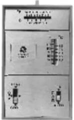
CDC Terminal Location and Typical Wiring
See page 15 for location of CDC terminals on unit.
Example of Common Busing
NOT PERMITTED
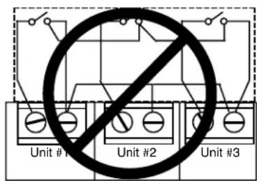
text_image
Unit #1 Unit #2 Unit #3INCORRECT Common Busing
Normally Open
Switch -
Unit Operational

text_image
CDC Terminals on Zoneline unitTypical Wiring (All Wiring Shown Is Field Supplied)
Remote Thermostat Control
In some installations, control of the operation of the unit at a location remote from the unit itself may be desired. A unit mounted high in the wall or over a door, for instance, where the unit-mounted controls are inaccessible, can be connected to a wall-mounted thermostat. Other installations may use remote thermostat control for design or performance enhancement. The unit is connected to the thermostat by low-voltage wiring which permits the operation of the unit to be selected and the temperature sensed at the thermostat.
Important Notes: Remote thermostat wiring should not be run through wall case. Thermostat wiring should exit the wall below the unit and enter the unit between room cabinet and chassis. Wire molding may be used to hide thermostat wiring. If a sub-base is used, the thermostat wiring may be concealed by the sub-base. Thermostat wiring should not be run parallel to line voltage wires since induced current may cause erratic operation.
All Zoneline 2900, 3900 and 5800 Series units are adaptable to Class 2 remote low-voltage thermostat. The only additional field-supplied components are the remote thermostat and wiring necessary to connect it.
The controls on the unit are not functional when the remote control function is used.
Resistance Heat Models
The Zoneline 2900 resistance heat units may be connected to a single-stage thermostat designed for use with cooling with electric heat systems. GE offers three thermostats compatible with the 2900 Series unit.
RAK163A1 —
a mechanical manual changeover thermostat requiring four connection wires.

RAK164D1 —
a solid-state digital manual changeover thermostat requiring five connection wires.
RAK164P1 —
a solid-state digital programmable thermostat requiring five connection wires.
The Class 2 Mode Switch (dip switch #4 on the auxiliary control board) must be set to the ON/UP mode to enable remote thermostat control. Refer to installation instructions packaged with the chassis.
Please see page 57 for installation recommendations for the remote thermostat wiring.
Compatibility of other thermostats considered for use with GE Zoneline units is the responsibility of the customer. The control voltage on the remote control conductors is 24 volts AC.
The AC voltage may not be compatible with some solid-state thermostats.
The fan speed for the 2900 Series in remote thermostat operation is selected by the connection of the fan wire from the thermostat to either the HIGH or LOW terminal on the unit. See the sketch of the unit terminals for the location of the HIGH and LOW fan-speed terminals. Operating the unit in low fan speed reduces the operating sound level of the unit.
Freeze Sentinel ^® remains operational if the unit is connected to a remote thermostat. The unit may be connected to a Central Desk Control (CDC) system and controlled with a remote thermostat when the CDC system has the unit in operation. See page 14 for additional information on the CDC system.
Unit temperature limiting switches are not functional when unit is connected to a remote thermostat.
Field Wiring Terminal
R - 24V AC
GL — Low-Speed Fan
GH — High-Speed Fan
B — Not Used on 2900
Y — Compressor
W — Heater
C — Common

text_image
CDC R GL GH B Y W C
natural_image
Pure geometric L-shaped line pattern without any text, numbers, or symbolsCommon
White — Heater
Yellow — Compressor
Black — Not Used On 410
Green — High-Speed Fan
Green — Low-Speed Fan
Red - 24V AC
CDC Terminal
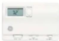
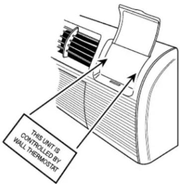
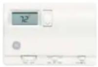
RAK806 Universal Control Cover Label
When a Zoneline unit is using a remote thermostat control, the RAK806 Universal Control Cover Label is recommended. The RAK806 is only available in a package of 10 labels.
The label is placed over the control panel to direct the user to the wall thermostat for operation of the Zoneline unit.
text_image
THIS UNIT IS CONTROLLED BY WALL THERMOSTATRemote Thermostat Control
Heat Pump Models
The Zoneline ^® 3900 and 5800 Series heat pump units may be connected to a single-stage cooling/two-stage heating thermostat designed for use with heat pump systems. GE offers two thermostats compatible with the 3900 and 5800 series units:

RAK148D1 — solid-state digital manual changeover thermostat requiring six connection wires.
RAK148P1 — solid-state digital programmable thermostat requiring six connection wires.
Please see page 57 for installation recommendations for the remote thermostat wiring. Compatibility of other thermostats considered for use with the GE Zoneline unit is the responsibility of the customer.
The control voltage on the remote control conductors is 24 VAC. The Class 2 Mode Switch, dip switch #4 on the auxiliary control board on both the 3900 Series and the 5800 Series, must be set to the ON/UP mode to enable remote thermostat control. Refer to installation instructions packaged with the chassis.
The fan speed for the 3900 and 5800 Series in remote thermostat operation is selected by the connection of the fan wire from the thermostat to either the HIGH or LOW terminal on the unit. See the sketch of the unit terminals for the location of the HIGH and LOW fan speed terminals. Operating the unit in low fan speed reduces the operating sound level of the unit.
When connected to a remote thermostat, the indoor-air-temperature sensing is shifted from the unit to the remote thermostat. For this reason, the units will operate slightly differently when connected to a remote thermostat. The following chart shows the unit operation when connected to a remote thermostat.
Temperature Boost option should not be used with remote thermostat operation since this will cause the unit to switch to resistance heat when outdoor temperatures are below 46^ F.
| Feature Heat Pump | Electric Heat | |
| Indoor Frost Control Yes | Yes | |
| Freeze Sentinel* | Yes Yes | |
| Auto Fan Speed No No | ||
| Electronic Temperature Limiting No No | ||
| Switch to Resistance Heat Based on Indoor Temperature | Determined by Remote Thermostat N/A | |
| Switch to Resistance Heat Based on Outdoor Temperature | Yes N/A | |
| Reverse Cycle Defrost Yes N/A | ||
| Simultaneous Resistance Heat with Heat Pump No N/A | ||
| Resistance Heat Lockout Yes N/A | ||
| "Smart Fan" Fan Cycle | Fan ON/AUTO Set On Remote Thermostat | Fan ON/AUTO Set On Remote Thermostat |
| Central Desk Control | Yes Yes |
Field Wiring Terminal
R — 24V AC GL — Low-Speed Fan
GH — High-Speed Fan B — Reversing Valve
Y — Compressor W — Heater
C — Common

text_image
CDC R GL GH B Y W C Common White - Heater Yellow - Compressor Black - Reversing Valve Green - High-Speed Fan Green - Low-Speed Fan Red - 24V AC CDC TerminalRemote Thermostat Control Selection Chart For Zoneline Packaged Terminal Units
| Zoneline Series Thermostat Model Type Function Low-Voltage Conductors | ||||
| 2900 | RAK163A1 | Mechanical | Cooling and Heating | 4 |
| RAK164D1 | Digital | 5 | ||
| RAK164P1 | Digital Programmable | 5 | ||
| 3900 and 5800 | RAK148D1 Digital | Single-Stage Cooling - 2-Stage Heating | 6 | |
| RAK148P1 | Digital Programmable | 6 | ||
Thermostat wire size - up to 60 feet AWG20 - up to 66 feet AWG18
Heat Pumps and Energy Savings
- GE Zoneline® heat pumps are designed to provide cost-efficient heat pump operation while monitoring room conditions to maintain comfort.
The units employ a logic system monitoring both outdoor and indoor temperatures to determine the heat source, thus increasing energy savings by operating longer in the heat pump mode.
Heat pumps save energy and cost less to operate than units with electric resistance heaters as the only heat source. Just as the EER of an air conditioner is an indication of the efficiency of the unit, COP (Coefficient of Performance) is the indication of the efficiency of the heat pump. This relative efficiency of a heat pump compares the unit to electric resistance heat. If a unit has a COP of 3.0, it means the unit will produce three times as much heat at rating conditions for the same electrical input wattage used for electric resistance heat.
The compressor is used in heat pump operation just as in air conditioning operation. In heat pump operation, the hot refrigerant gas is directed to the indoor coil rather than to the outdoor coil. Room air that circulates over the indoor coil gains heat from the coil rather than losing heat to the coil as during cooling operation.
As the outdoor temperature falls, the heat pump is able to extract less heat from the outdoor air to raise the temperature of the indoor air. For this reason, all packaged terminal heat pumps also have electric resistance heaters as backup to heat pump operation. At some point, the heat pump is unable to provide sufficient heat to adequately warm the room. Many Packaged Terminal Heat Pumps cease heat pump operation and change to more expensive resistance heat at some pre-determined outdoor temperature to compensate for the inability of the heat pump to maintain room temperature. This point, called the “switchover point,” is usually at an outdoor temperature where savings from heat pump operation may still be realized, if the unit is designed to maintain room comfort at the lower outdoor temperatures.
Balance Point
An important consideration in the selection of a heat pump unit is the "balance point" of the installation. Virtually every room is unique—with different insulation, different sizes and types of windows, different types of construction, different directional exposures. All these variables, as well as geographical location, must be considered in order to determine the balance point, the point at which the heat pump is unable to produce enough heat to compensate for the heat loss of the room or area being heated. For these reasons a consulting engineer should be engaged to calculate the heat loss and specify the heat pump unit required.
GE offers two series of Zoneline heat pump units—the 3900 Series with standard microprocessor controls and the 5800 Series with highly featured microprocessor controls—and both series react to the indoor temperature as well as the outdoor temperature in determining the heat source to provide comfortable room conditions and energy savings. This determination of the heat source based on the indoor temperature helps provide a more comfortable room.
Heat Pumps and Energy Savings
Heat Pump Operation — Zoneline 3900 and 5800 Series
Heat sources: Heat pump, heat pump and simultaneous electric resistance heat or electric resistance heat.
Zoneline heat pumps employ a highly featured microprocessor control system interfaced with thermistors to accurately measure indoor air temperature, outdoor air temperature, indoor coil temperature and outdoor coil temperature. This system allows the microprocessor to precisely and predictably react to changing conditions in order to provide a very advanced packaged terminal heat pump operating system.
The Zoneline heat pumps are designed to help ensure a comfortable room. When "HEAT" is selected, the unit will determine if the room air is warm enough to satisfy the thermostat setting. If the temperature at the unit sensor is below the desired temperature, the electric resistance heater will be utilized to warm the room to the point where the thermostat is satisfied. This feature is designed to allow the temperature of an unoccupied room to be maintained at an energy-saving level without inconveniencing the room occupant. Once the thermostat has been satisfied, the resistance heater will turn off and the heat pump will operate as shown in the Heat Source Logic chart until the thermostat calls for heat again. The unit will operate in this manner even if connected to a Central Desk Control.
Zoneline Heat Pump Heat Source Logic
| ROOM TEMPERATURE VS. THERMOSTAT SET POINT | Above 46°F | Between 46°F and 25°F | Below 25°F |
| Less Than 1.8°F Below | Heat Pump Heat Pump* | Full Resistance Heat | |
| 1.8°F to 2.7°F Below | Heat Pump | Heat Pump + Supplemental Heater | Full Resistance Heat |
| More than 2.7°F Below | Heat Pump | Full Resistance Heat | Full Resistance Heat |
* If the "Temperature Boost" switch (dip switch #8) is in the "ON" position the supplemental simultaneous heater will be used with heat pump operation. Simultaneous supplemental heater: 1.0 KW @ 230 V; 0.8 KW @ 208V; 1.0 KW @ 265V.
The "Temperature Boost" option utilizes the supplemental simultaneous heater at the same time as heat pump operation when the outdoor temperature is below 46°F regardless of the indoor air temperature. The chart above indicates the heat source of the heat pump under various indoor and outdoor conditions. The unit is designed to provide heat pump savings without sacrificing room comfort.
The Quick Heat Recovery feature is not affected by the Heat Source Logic shown in the chart below. For more information about the Quick Heat Recovery Feature, see page 9. The full heat output of the resistance heater is dependent upon circuit amperage and the power connection kit used. See pages 3 and 42–43 for information on power connection kits and available heater capacities.
A heat pump switch is provided in the auxiliary controls to allow the unit to operate only in resistance heat. The use of this option significantly increases the cost for heating.
Heat pump defrost — Zoneline 3900 and 5800 Series
Zoneline heat pumps utilize a reverse-cycle demand defrost system to extend heat pump operation and increase savings from extended operation. The microprocessor determines the need for defrosting by criteria based on continuous compressor running time, outdoor air temperature, outdoor coil temperature and the rate of temperature change of the outdoor coil. When defrosting is required, the unit reverses the flow of refrigerant to direct the hot gas into the outdoor coil to melt the frost buildup. Before and after the reverse-cycle defrosting, the unit shuts off the compressor to allow the refrigerant pressures to equalize throughout the system. This eliminates the possibility of a loud reversing noise. During these periods of pressure equalization, the full resistance heat capacity of the unit is activated to help ensure room comfort conditions during the defrost cycle. The unit remains in the defrost cycle for a minimum of two minutes up to a maximum of nine minutes. The defrost cycle terminates when the outdoor coil reaches a temperature of 68^ F or the maximum time has been reached.
Heat pump condensate
See page 34 for information on heat pump condensate. The Zoneline 3900 Series heat pumps may be ordered with a factory-installed Internal Condensate Removal (ICR) system to minimize the amount of condensate water draining from the unit during heat pump operation. The ICR system has proven to be an effective means of minimizing the amount of heat pump condensate dripping from the unit. However, if the requirements of a particular installation will allow no dripping of condensate water from the wall case, the installation of an internal or external drain system is recommended.
Units with ICR may not be installed in seacoast or corrosive environment applications.
Application Comments
Use and Care Manual and installation instructions are shipped with Zoneline® units. It is important that any air conditioning system be properly sized and applied in order to achieve the desired temperature and humidity levels in the space to be conditioned. Air conditioners are designed primarily to provide heating and cooling with the additional benefit that during operation in the cooling mode, the units also remove some moisture from the conditioned space. The following are some brief application comments on undersizing, oversizing, heating, wall coverings, and air infiltration: all are important in the proper matching of the heating/air conditioning system to the building structure.
Undersizing: If an air conditioner is undersized (cooling capacity is less than required for a specific application), the unit will typically not be able to cool the space down to the desired temperature (thermostat set point), nor be able to remove enough moisture from the air. A result could be a warm and humid or warm and dry conditioned space.
Oversizing: If an air conditioner is oversized (cooling capacity is greater than required for the specific application), the unit will typically cool the space down to the desired temperature (thermostat set point) too quickly. The compressor then begins to cycle on and off. Dehumidification only takes place when the compressor is operating. A typical result in a hot/humid climate could be a cool but excessively humid space.
Heating: Undersizing can result in not being able to maintain the desired temperature level within the conditioned space.
Wall Covering: Use of a non-permeable wall covering (some paints, some wallpapers, and other types of coverings) which severely restricts passage of air or water vapor can cause a severe moisture problem. Typical results could be staining of room surfaces, wall damage, as well as mold and mildew growth in hot/humid climates.
Air Infiltration: Excessive air infiltration can magnify problems associated with undersizing or oversizing of an air conditioner unit and can be the root cause of insufficient cooling, dehumidification, or heating. Some sources of air infiltration include vents, gaps around windows and doors, and improperly sealed floor, ceiling and wall joints.
Recommendation: For the above reasons it is strongly recommended that a professional engineer be retained to match the Zoneline unit with the building structure.
Air Distribution
Zoneline packaged terminal air conditioners and heat pumps discharge air from the top of the unit through reversible two-position discharge louvers. Unit discharge louvers are reversed by removing the room cabinet from the unit, removing seven screws that hold the louver section in place, removing the louver section and rotating it end for end, reinstalling the louver section in the room cabinet with the seven screws, and reinstalling the room cabinet on the unit. The unit is shipped from the factory with the discharge louvers at an angle of 50^ off vertical. In the alternate position, the louvers will be at an angle of 40^ off vertical. All room cabinets return air through the front of the unit.
High Wall Mount — For units mounted high in the wall, the discharge louvers should be at a setting that provides the most horizontal air discharge. Recommended installation is at least 3" below the ceiling. In

natural_image
Simple diagram showing a rectangular object with curved arrows indicating motion or flow, enclosed in a rectangle (no text or symbols)installations where units are close to the ceiling, the greatest horizontal discharge angle can be obtained by removing the discharge grille from the room cabinet.
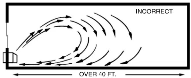
Supply Air Throw — One Zoneline unit should not be required to do a job obviously requiring two or more units. Units should be located around large rooms according to calculated loads or in such fashion as to achieve balanced air distribution in all parts of the room. The single unit in the "Incorrect" illustration below obviously cannot condition the entire room. Add a second unit as shown in the "Correct" illustration.
text_image
INCORRECT OVER 40 FT.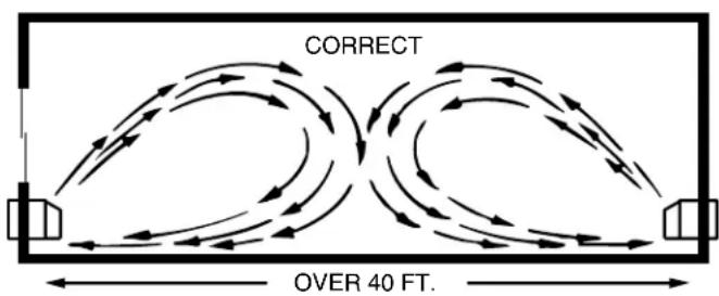
text_image
CORRECT OVER 40 FT.
natural_image
Diagram of a mechanical component with a 50-degree angle label (no other text or symbols)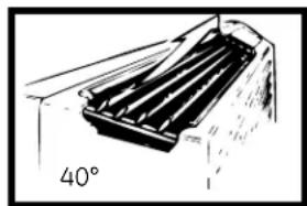
natural_image
Diagram of a heat exchanger or cooling unit with a 40-degree angle label (no text or symbols on the diagram itself)Dimensions
RAB71A WALL CASE
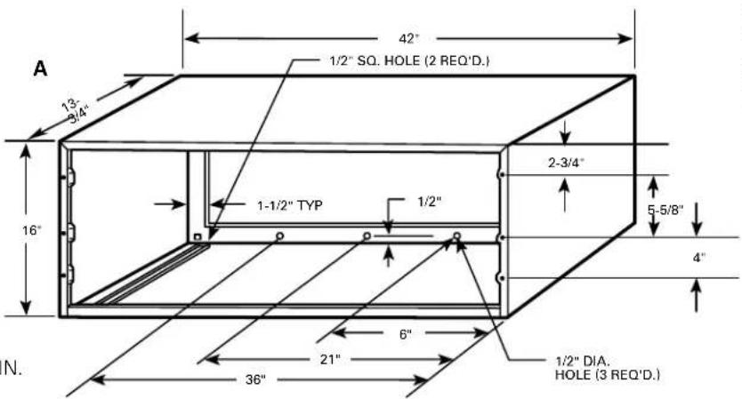
text_image
A 13- 3/4" 42" 1/2" SQ. HOLE (2 REQ'D.) 16" 1-1/2" TYP 1/2" 2-3/4" 5-5/8" 4" N. 36" 21" 6" 1/2" DIA. HOLE (3 REQ'D.)Additional
Wall Case Depths
RAB7116 - 16"
RAB7124 - 24"
RAB7128 - 28"
RAB7131 - 31"
WALL OPENING
16-1/4" MIN. × 42-1/4" MIN.
RAB77 WALL CASE
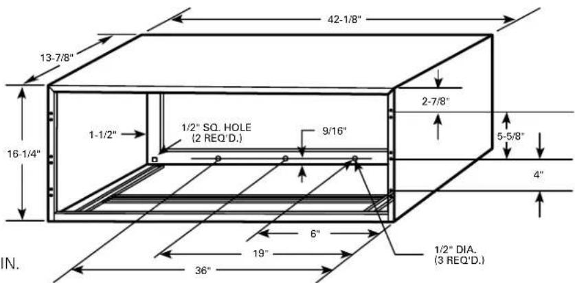
text_image
42-1/8" 13-7/8" 1-1/2" 16-1/4" 1/2" SQ. HOLE (2 REQ'D.) 9/16" 6" 19" 36" 1/2" DIA. (3 REQ'D.) 2-7/8" 5-5/8" 4" IN.WALL OPENING
16-1/2" MIN. × 42-3/8" MIN.
WALL CASE WITH CHASSIS INSTALL

text_image
RAB71 = 42" RAB77 = 42-1/8" GRILLE TOP VIEW RAB71 = 20-7/8" RAB77 = 21" 7-1/8" INSIDE SIDE VIEW RAB71 = 16" RAB77 = 16-1/4" OUTSIDE ROOM CABINET ROOM CABINET 42"WALL CASE WITH
SUB-BASE

text_image
FRONT VIEW* 13" 1-7/16" 3-1/2" 12-3/4" 12" 9-3/8" 2-1/2" KNOCKOUTS (ENCLOSURE) 4 REAR; 4 BOTTOM LEVELING SCREW SEE PAGE 32 FOR KNOCKOUT LOCATION DIMENSIONS.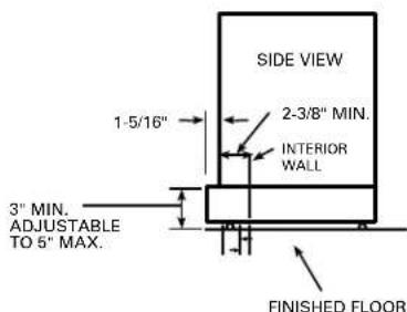
text_image
SIDE VIEW 1-5/16" 2-3/8" MIN. INTERIOR WALL 3" MIN. ADJUSTABLE TO 5" MAX. FINISHED FLOOR*SHOWN WITH ACCESS COVERS REMOVED.
NOTE: CAUTION - REMOVE KNOCKOUTS FROM INSIDE OUT.
Installation instructions packed with wall case. See page 25 for additional information concerning outdoor weather panel and case stiffener.
Wall Case
A choice of wall cases is available for Zoneline® units.
RAB71A — This insulated case is constructed of heavy-gauge galvanized steel and finished with a baked-enamel finish for protection and appearance. Design of the case provides for support of the chassis and free draining of any water entering the wall case. A petroleum microcrystalline wax is applied at critical points of fabrication to seal against moisture. The dimensions of the RAB71 wall case are 42" wide by 16" high by 13-3/4" deep, the same dimensions as the original wall case for GE Zoneline units built in 1961. The RAB71 wall case is also available in depths other than the standard depth. It is available on special order as: RAB7116
- 16" deep; RAB7124 - 24" deep; RAB7128 - 28" deep; and RAB7131 - 31" deep. All these special-order deep wall cases are insulated and have sheet-metal dividers, or splitters, to prevent the recirculation of condenser discharge air.
RAB77 — This non-insulated wall case is molded from fiberglass-reinforced polyester compound. This SMC (Sheet-Molded Compound) wall case offers outstanding strength, durability, color retention, water integrity and corrosion resistance. The dimensions of the RAB77 wall case are 42-1/8" wide by 16-1/4" high by 13-7/8" deep.
- Both wall cases are of universal design, accepting all Zoneline chassis of current design as well as all GE Zoneline chassis produced since 1961.
- Drain holes are provided in the rear of the wall case to permit excessive cooling condensate water, heat pump condensate or precipitation entering the wall case to drain freely. A drain kit may be connected to the wall case to control any water draining from the wall case. See page 35 for information on RAD10 Drain Kit.
RAK901L — For installations where the wall case extends into room, RAK901L is an insulation kit that can be used with the RAB77 or any existing non-insulated wall case to minimize the possibility of condensation forming on the indoor side of the case during the winter.
Sub-Base
The sub-base is an optional accessory for the Zoneline unit and is presented with the wall case information since the decision to use or not use a sub-base in the installation is a factor in the location of the wall opening for the unit. National Electrical Code ^® requires that air conditioning units connected to voltages in excess of 250 volts be “permanently connected.” There are also some installations where units connected to voltage sources under 250 volts may also need to be “permanently connected.” If you are in doubt about the requirements for a particular installation, consult Article 440 of the NEC or the local electrical inspector. These requirements are designed to protect personal safety and should be strictly followed. Although NEC is cited here as a reference, all electrical wiring and installations must conform to any and all local electrical codes and regulations. "Permanent connection" generally means wiring to the unit must be contained in an enclosed "chaseway," where access to the wiring connections is more restrictive than a normal line cord plugged into a receptacle. NEC requirements may be met by using flexible or rigid conduit to contain the wiring between the unit and a junction box that contains the wiring connections. The conduit is connected to the unit and to the junction box with connectors to hold the conduit in place.
The junction box may be located in the floor or the wall of the structure but only approved connectors may be used outside the unit or the junction box. The sub-base is UL ^® listed as a junction box for permanent connection of a Zoneline unit.
Using a sub-base in an installation requiring permanent connection provides a convenient, consistent location for unit wiring to be connected to building wiring. The use of a sub-base is not required, but the convenience and the improved aesthetics it offers makes the use of a sub-base a viable means of permanent connection.
RAK204U — The RAK204U Series of sub-bases provides a variety of designs that fit the site needs and are available for use with Zoneline PTAC/PTHP units. The RAK204U will most likely be used for support of the wall case and unit. The RAK204U is the same physically as the other sub-bases except there is no receptacle installed. Receptacles and wiring can be field installed and, by using the RAK205CW chaseway and the RAK4002 junction box perform the same function as any of the other sub-base kits by selecting the correct receptacle and installing it in the interior mounting plate inside the RAK204U.
208/230-volt receptacles can also be mounted in the cover plate for easy access when direct connect wiring is not required. 265-volt units are to be "Permanently (or Direct) Connected" and the external receptacle (when wiring is not enclosed in a chaseway) does not meet this requirement.
A knockout for a fuseholder or a disconnect is also provided in the cover plate.
RAK204U — No receptacle, no wiring; will accept any 15-, 20-, 30-amp receptacle and wiring. No chaseway is included. RAK205CW chaseway must be ordered separately.
The 230/208-volt sub-bases below include a short, sub-base power connection kit. Since sub-base connected units are not considered to be line-cord connected, a Leakage Current Detection and Interruption or Arc Fault Current Interrupter device is not necessary.
The junction box (RAK4002A for 2900 and 3900 Series units; RAK4002B for 5800 Series units) that mounts on the chassis of 230/208-volt sub-base connected units must be purchased separately.
RAK204D15P 208/230-volt 15-amp receptacle. Receptacle is NEMA6-20R with 18" of #12AWG wires attached to the receptacle. Short power connection kit included. Chaseway included.
RAK204D20P 208/230-volt 20-amp receptacle. Receptacle is NEMA6-20R with 18" of #12AWG wires attached to the receptacle. Short power connection kit included. Chaseway included.
Sub-Base (Continued)
RAK204D30P 208/230 volt 30-amp receptacle. Receptacle is NEMA6-30R with 18" of #12AWG wires attached to the receptacle. Short power connection kit included. Chaseway included.
The junction box (RAK4002A for 2900 and 3900 Series units; RAK4002B for 5800 Series units) that mounts on the chassis of 230/208 volt sub-base connected units must be purchased separately.
Sub-bases for the 265-volt units:
RAK204E15 265-volt 15-amp receptacle. Receptacle is NEMA7-15R with 18" of #12AWG wires attached to the receptacle. Chaseway included.
RAK204E20 265-volt 20-amp receptacle. Receptacle is NEMA7-20R with 18" of #12AWG wires attached to the receptacle. Chaseway included.
RAK204E30 265-volt 30-amp receptacle. Receptacle is NEMA7-30R with 18" of #12AWG wires attached to the receptacle. Chaseway included.
The junction box for 265-volt units is shipped with the chassis since all 265-volt units are to be "permanently (or direct) connected."
The power connection kit is not included
There are separate internal compartments to permit separation of low-voltage (Class 2) connections from line-voltage connections as required by NEC. Conduit containing building wiring enters the sub-base through knockouts located in the rear or bottom of the sub-base and is not accessible when the wall case is installed.
The sub-base attaches to the RAB71 wall case with two clips (field-assembled) that are screwed into pre-drilled holes in the bottom front flange of the wall case. It attaches to the RAB77 wall case with clips that fit over molded ribs without requiring the use of screws into the wall case. See page 33 for illustration. Since the sub-base extends under the wall case, clearance from the inner edge of the wall case to the finished wall must be 2-3/8" or greater. The sub-base has four leveling legs and adjustable side channels to enable the area under the wall case to be enclosed. Clearance from the bottom edge of the wall case to the finished floor must be between 3" and 5".
The sub-base may be used as support for the chassis and wall case in installations where the wall is of insufficient thickness to provide secure mounting of the wall case.
Wall Case Installation Data
General
Generally, Zoneline units are installed 3" to 5" above the floor (flush to finished floor installation is possible) as near to the center of the room as possible; underneath a window or a glass panel is typical. Normal installation of the wall case allows installation flexibility; from flush with the finished interior wall to a minimum of 1/4" of the wall case extending beyond the finished exterior of the building. Special consideration must be given to installations where the wall case does not extend a minimum of 1/4" beyond the finished exterior wall. See pages 30 and 31 for information on this type of installation. The unit may be installed high in the wall and these installations usually require a remote thermostat and are discussed on pages 15 and 16.
Regardless of the installation, there are several things to consider when selecting a location for installing the unit. For instance, drapery location could interfere with air discharge, and placement of furniture may have an impact on the performance of the unit. The following information is intended to minimize installation problems and assure you of trouble-free installation.
Refer to page 21 for required wall opening dimensions. Minimum recommended interior and exterior case projections for standard wall thicknesses are shown in the drawings in this manual. The case may be installed flush with the finished indoor wall. Special attention must be paid to room-side case projection when the unit is installed in a ducted application as shown on pages 38 and 39.
In walls thicker than 13-1/2" for line-cord-connected units and 11-1/8" for sub-base installations, it may be necessary to install a field-fabricated case extension or use one of the special-order RAB71 deep wall cases. Such extension must be carefully flashed and sealed both to the wall case and to the wall to ensure water integrity. This is necessary to ensure that any water entering the wall case, either from operation of the unit or from other sources, such as rain storms or from washing the exterior of the building, will drain from the case without the possibility of capillary action drawing the water into either the room or the wall cavity. In an installation where the case is recessed less than 3" from the outside surface, flashing and sealing may be all the modification necessary. In such an installation, the sides and top of the wall opening must be waterproof to prevent moisture from seeping into and damaging the walls. See pages 30 and 31 for suggested detail. Since the installation of a case extension requires a considerable amount of attention, we recommend using one of the deep wall cases if the standard case is not of sufficient depth.
Mounting an outdoor grille or louver section to the building face may cause a space between the outdoor coil and the louver section. Air splitters, aligned with the ends of the outdoor coil, must be installed between the outdoor coil inlet and outlet air streams. Gaps between the outdoor coil and the louver section may allow condenser air recirculation and affect the operation of the unit. See page 41 for requirements for custom louvers.
The wall case should be level from side to side and from level to 1/4 bubble tilt to the outdoors. The condensate disposal system in the unit is designed to dissipate the condensate water generated during cooling operation in accordance with ARI standards and actually uses this water for maximum unit efficiency. A level unit will also ensure proper performance of the Internal Condensate Removal (ICR) system optional on heat pump units.
Wall Case Installation Data (Continued)
For new construction, early planning with the architect is necessary. Unit location, electrical connection locations and wall openings of the proper dimensions are essential to avoid the necessity of rework, fillers, framing, moving electrical outlets and other expensive modifications.
For existing construction it is important that carpentry, masonry and electrical work be performed by competent, qualified personnel. Since installations in existing construction may involve removal of building material from the structure, locating the wall case must be done correctly.
Architectural Window/ Louver Installation
Many installations utilize an architectural window/louver combination to enhance the exterior appearance of the building. The exterior grille for the air conditioner is built as an integral part of the window frame. An internal drain system is highly recommended for these installations (see page 36). When this type of installation is made, there must be provision in the grille work for condensate water to drain to the exterior and not be routed back into the interior of the building or into the wall cavity. Failure to allow for the drainage of condensate water can cause extensive damage to structural components. The problems associated with the lack of condensate drain consideration often show up shortly after the air conditioners are turned on in a new building. New buildings that have been virtually wide-open during construction have a significant amount of moisture in the air and in the building components that the air conditioners start removing as they operate. The free area in the louver section must also comply with the requirements shown on page 41.
The wall case should be anchored to the architectural window/louver section to reduce air infiltration and excessive vibration of the chassis and wall case during unit operation. Field-fabricated and installed case angles are the recommended method of securing the wall case to the window/louver framework.
Window, Curtain and Panel Wall Construction
With this type of construction, provision for support of the unit, other than by the wall itself, is often required. Such support may be in the form of wood or metallic material of the proper thickness to maintain a level case. This additional support should be located both near the wall and at the front of the wall case. Sub-base (RAK204 Series) with four leveling legs provides an excellent support for the unit in this type of installation. See page 28 for details of this type of installation.
In existing construction, common practice is to remove a pane of glass, metal, wood, or other construction material and build a frame around the wall case. Similar filler panel material may be installed around the case for appearance and weather seal.
Masonry Wall Construction
The wall case should be installed during construction and lintels should be used to support the blocks above the wall case. The wall case will not support the concrete block.
The installation instructions show how the wall case must be secured to the masonry and caulked. Do not remove the cardboard stiffener supplied with the wall case until ready to install the chassis. See page 29 for details of installation in masonry wall.
For existing masonry construction, wall openings must be made by removing concrete blocks to achieve the proper-size opening. Consult the builder, architect or owner to determine the necessity for lintels to support the block above the wall case.
Anchor bolts are normally required to secure the case to the wall and shims may be required to prevent distortion of the wall case when securing the wall case to the wall. Field-supplied case angles can be used to position and secure the wall case to the wall and to cover oversized wall openings.
Brick, Frame, Stucco and Shingle Construction
For new construction, the opening for the wall case should be framed and the wall case inserted into the opening during construction. Lintels should be used when the building material is heavy and is not self-supporting (such as brick). The wall case will fit an opening of six courses of standard brick or five courses of jumbo brick. Wall framing in this type construction is normally on 16" centers and the wall case will fit a framed opening spanning three 16" O.C. 2" × 4" stud spaces.
For existing construction, the indoor and outdoor wall will need to be cut out, allowing for clearances of 1/8" on all sides of the wall case. Work should begin on the inside wall. Cut the correct dimensions and mark (using drill holes) the outside wall from each corner of the inside cutout. Studding that interferes with the opening must be removed and a suitable frame constructed to secure the wall case and provide adequate support for case and chassis.
As shipped, the RAB71 Series or RAB77 is ready for installation.
Preparation of the Wall Case for All Types of Construction,
Do not remove the stiffener from inside the wall case or the weather closure panel from the outside face of the wall case until the outdoor grille and chassis are ready to be installed. Installation of Wall Case in Wall Opening
- Position the wall case into the wall. The room-side edge of the RAB71 or RAB77 wall case should be at least flush with the finished wall for line-cord installations and permanent-connection installations when no sub-base is used, and should project into the room at least 2-3/8" when a sub-base is used. If the minimum exterior dimensions are not met, refer to pages 27 and 28. The outside edge of the wall case should extend at least 1/4" beyond the outside wall. This is necessary for proper caulking, to prevent sealing the drain holes in the rear flange of the wall case, and to facilitate the installation of an accessory drain, if used.
The wall case should be level from side to side and from level to 1/4 bubble tilt to the outdoors. The condensate disposal system in the unit is designed to dissipate the condensate water generated during cooling operation in accordance with ARI standards and actually uses this water for maximum unit efficiency. A level unit will also ensure proper performance of the Internal Condensate Removal (ICR) system optional on heat pump units.
- The wall case should be secured to the wall at both sides. Use a minimum of two screws or other fastening device on each side. See Figure 2 on page 26. Mark the wall case on each side 2" from the bottom and 2" from the top at a point where basic wall structure is located. Drill wall case and use fasteners appropriate for wall construction. All holes for fasteners in the side of the wall case must be at least 2" up from the bottom of the wall case. Never locate screws or put other holes in the bottom of the wall case. The only exception is when an RAD10 drain kit is installed to connect to an internal drain system. See page 36 for RAD10 drain kit information.
If the wall opening is greater than the case dimensions, spacers must be used on the sides between the wall case and the wall support structure to prevent distorting the wall case.
- Caulk or gasket the entire opening on the outside between the wall case and exterior wall surface (four sides) to provide total water and air seal.
- Caulk or gasket room-side opening between wall case and interior wall surface (four sides). Opening beneath or around the wall case can allow outdoor air to leak into the room, resulting in increased operating costs and improper room temperature control.
Care should be taken in location of electrical supply entry in relationship to wall sleeve to assure access to receptacle or junction box once unit is installed.
- Refer to page 43 for maximum power cord length.
- Permanently connected units close to finished floor must allow for conduit clearance.
Case Angles
In some installations, such as curtain walls, window walls, or where the structural material of the wall is insufficient to support or fasten wall case to, case angles may be used. Case angles are pieces of steel or other material of similar structural strength that are formed to a 90° angle, with holes to fasten the case angle to the wall case and to the structural component of the wall surrounding the wall case.
The following describes the procedure when field-fabricated and -installed case angles are applied.
- Position case angles around top and sides of wall case at the desired location. Position case angles vertically on each side of wall case to provide a level installation.
- Mark wall case through holes in case angles. The lowest hole on the sides of the wall case must be a minimum of 2" above the bottom of the case.
- For RAB71 wall case drill 5/32" -diameter holes at locations marked on wall case in Step 2, and assemble angles to wall case using #10 x 1/2" self-tapping screws. For RAB77 wall case follow the same procedure except use a #10 x 1/2" bolt, washer and nut to attach case angles to case. Install screws or bolts from outside wall case.
- Do not drill any holes in bottom of wall case. Do not distort wall case.
- Do not use case angles for a lintel.
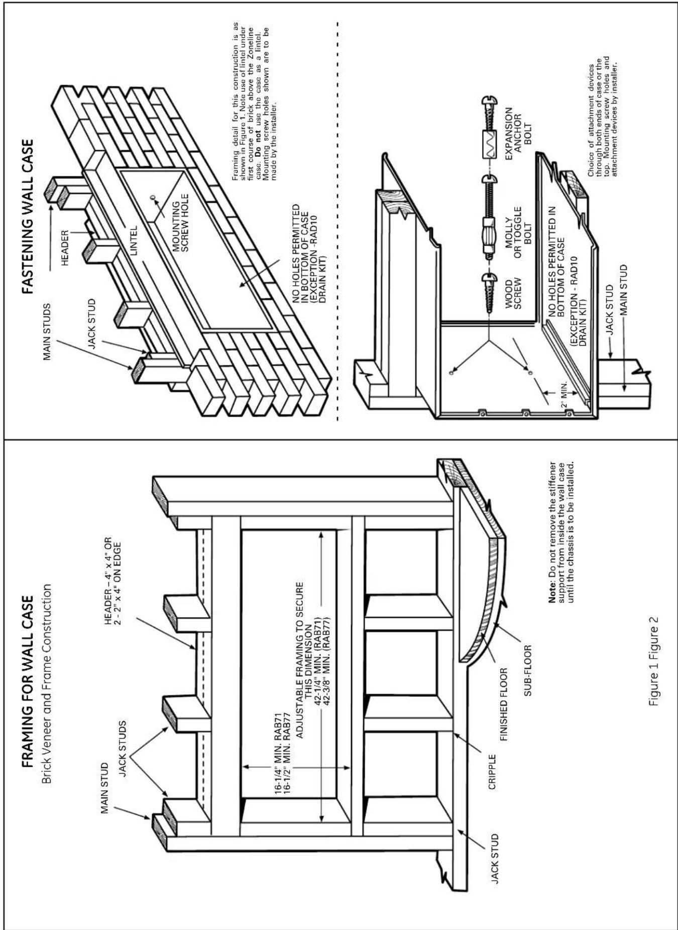
WALL SECTION - DETAILED SIDE VIEW
Frame and Brick Veneer Installation
Sub-Base Connected

text_image
CAULK* STEEL LINTEL CAULK* RAB71 13-3/4" RAB77 13-7/8" 20-7/8" (RAB71) 21" (RAB77) MOUNTING SCREWS BY INSTALLER RAB71 16" RAB77 16-1/4" OUTDOOR GRILLE ROOM CABINET 2" MIN. WALL CASE CAULK* 1/4" MIN. FINISHED FLOOR OR TOP OF CARPET WALL RECEPTACLE (BY OTHERS) POWER SUPPLY CONDUIT *Caulk around perimeter of wall case all four sides where it joins the building - Interior and Exterior.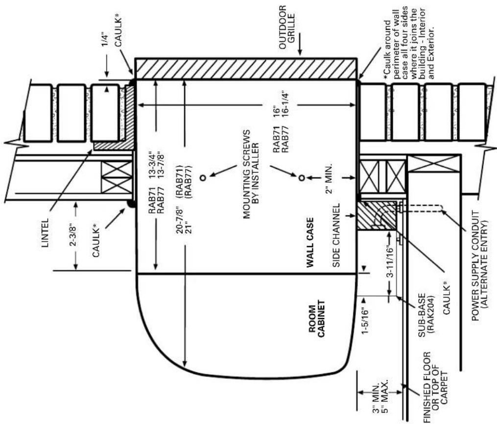
text_image
LINTEL 2-3/8" CAULK* 1/4" CAULK* RAB71 13-3/4" RAB77 13-7/8" 20-7/8" (RAB71) 21" (RAB77) MOUNTING SCREWS BY INSTALLER RAB71 16" RAB77 16-1/4" OUTDOOR GRILLE ROOM CABINET WALL CASE SIDE CHANNEL 2" MIN. 3" MIN. 5" MAX. 1-5/16" 3-11/16" FINISHED FLOOR OR TOP OF CARPET SUB-BASE (RAK204) CAULK* *Caulk around perimeter of wall case all four sides where it joins the building - Interior and Exterior. POWER SUPPLY CONDUIT (ALTERNATE ENTRY)WALL SECTION - DETAILED SIDE VIEW
Window, 2" curtain or panel wall installation with rag rear grille extended beyond outer wall surface
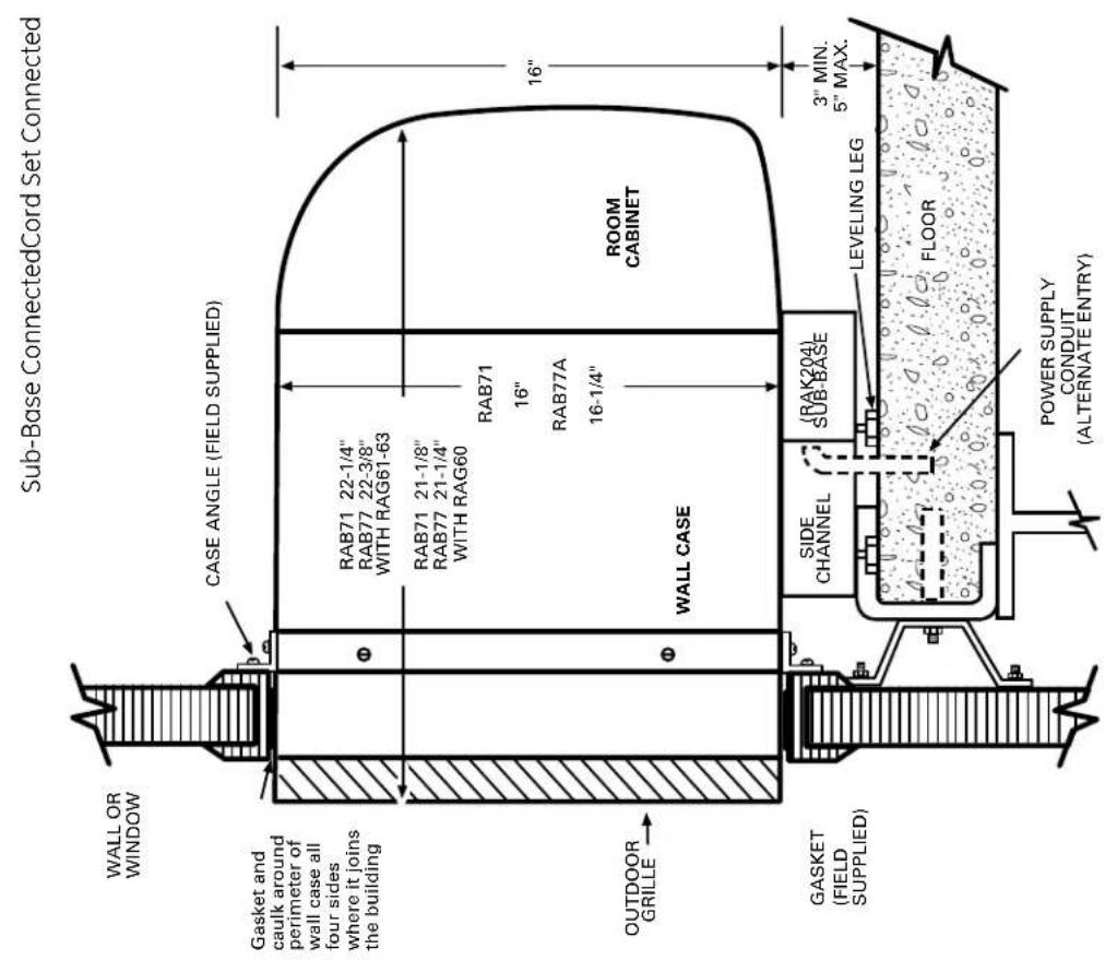
text_image
Sub-Base ConnectedCord Set Connected WALL OR WINDOW Gasket and caulk around perimeter of wall case all four sides where it joins the building CASE ANGLE (FIELD SUPPLIED) RAB71 22-1/4" RAB77 22-3/8" WITH RAG61-63 RAB71 21-1/8" RAB77 21-1/4" WITH RAG60 RAB71 16" RAB77A 16-1/4" ROOM CABINET OUTDOOR GRILLE WALL CASE SIDE CHANNEL (RAK204) SUB-BASE LEVELING LEG 3" MIN. 5" MAX. GASKET (FIELD SUPPLIED) FLOOR POWER SUPPLY CONDUIT (ALTERNATE ENTRY)
text_image
Gasket and caulk around perimeter of wall case all four sides where it joins the building CASE ANGLE (FIELD SUPPLIED) RAB71 22-1/4" RAB77 22-3/8" WITH RAG61-63 RAB71 21-1/8" RAB77 21-1/4" WITH RAG60 RAB71 16" RAB77 16-1/4" ROOM CABINET WALL CASE USE NO SCREWS IN BOTTOM OF CASE RECEPTACLE (BY OTHERS) MIN. 2 SUPPORTS FIELD SUPPLIED FLOORWALL CASE INSTALLATION - CORD SET CONNECTED
Example: block and veneer - dimensional data and comments
are also applicable to other types of construction

text_image
FINISHED EXTERIOR WALL CAULK* CASE RAB71 42" RAB77 42-1/8" CAULK* A CAULK* RAB71 13-3/4" RAB77 13-7/8" CAULK* C FINISHED EXTERIOR WALL ROOM CABINET 2-1/2" 27-1/4" TOP VIEW ADJACENT WALL| Dimension | Manufacturer RequiredMinimum Installation Clearance |
| A | 1/4" (See note 1) |
| B | Allow For Electrical Wiring 0" Min. (See page 27) |
| C | 0" Minimum |
| D | 0" Minimum 2" RecommendedSee pages 38-39 for ducted application. |
| E | 3" Minimum |
| NOTE:1. FOR OUTSIDE FLUSH MOUNTING SEE PAGE 35 FOR DRAIN INSTALLATION. | |
* Caulk around perimeter of wall case all four sides where it joins the building - Interior and Exterior.

text_image
MAX. WALL THICKNESS 13-1/8" SIDE VIEW OF ALTERNATE HIGH MOUNT With conduit power supply. E CAULK* A CAULK* ROOM CABINET 7-1/8" RAB71 13-3/4" RAB77 13-7/8" 16" RAB71 16-1/8" RAB77 CAULK* B CONDUIT FIELD SUPPLIED FINISH FLOOR *Caulk around perimeter of wall case all four sides where it joins the building - Interior and Exterior.
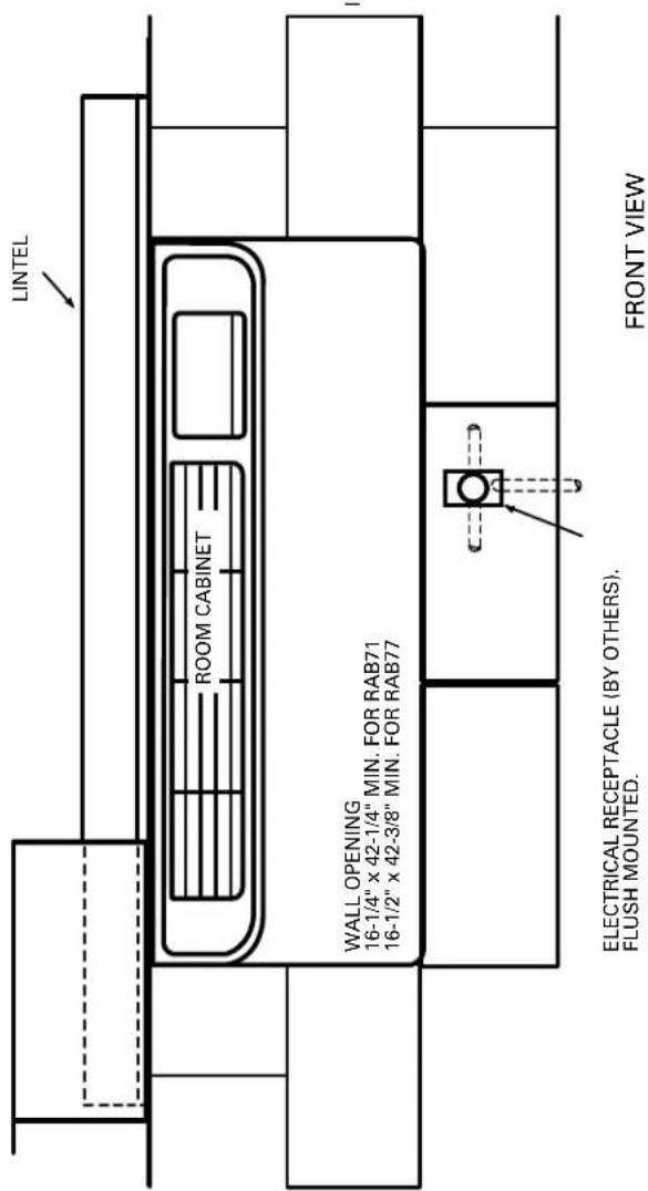
text_image
LINTEL ROOM CABINET WALL OPENING 16-1/4" x 42-1/4" MIN. FOR RAB71 16-1/2" x 42-3/8" MIN. FOR RAB77 ELECTRICAL RECEPTACLE (BY OTHERS). FLUSH MOUNTED. FRONT VIEWSee page 43 for line cord length.
METAL CASE EXTENSION FOR WALLS DEEPER THAN 13-1/8" (11-1/8" WITH SUB-BASE) Field fabricated – ge recommends the use of one of the deeper RAB71 wall cases offered as special order items
Zoneline units can be installed in walls of greater depth than the wall case. Where the case recession is less than
3" and where it is possible to waterproof the exposed sides and top of the opening, the suggested procedure
sides and top of the opening, the suggested procedure is to apply a flashing to the bottom of the wall case as shown on page 31. Where waterproofing is questionable
or not possible, or for installations in walls of greater depth, the following is a suggested application
procedure. It involves the field fabrication of a case extension. Since the wall case is a water-bearing container, the extension likewise must also be water
container, the extension likewise must also be water-bearing and the connection between the two must be
watertight. The case extension must contain splitters to prevent recirculation of the outdoor air circuit.
1. The case extension is field fabricated. The extension depth "D" should allow for a minimum outdoor
depth "B" should allow for a minimum outdoor projection of 1/4". This allows for room cabinet clearance to the finished wall and ample surfaces.
clearance to the finished wall and ample surfaces to apply sealant or caulking for a tight weather seal between the completed wall case/extension assembly
and the wall opening. It is recommended that the extension be painted and corner and lap joints be
additionally sealed with a quality-grade sealant.
[Non-Text]
The Ground Truth image displays a single, solid horizontal line. According to Rule 2 (UNDERSCORE & LINE RULES), if the GT contains lines used for stylistic emphasis or as background elements (like a ruled line), the OCR result must ignore them. The line in the GT is clearly a stylistic/background line, not a placeholder for text. Therefore, the OCR should not have output any underscores. Outputting `____` constitutes an error under Rule 2, as it hallucinates placeholder symbols where none are semantically intended. No punctuation mismatch or formatting transformation applies here because the content is purely symbolic and not textual.
(No text)
SPLITTER BETWEEN
AIR INTAKE AND DISCHARGE
DISCHARGE
(No text)
m : x = 1 或 3x + 4y + 1 = 0
1 + u1 - 1 = ( 1 + u) u1 < 1 = u
( x - 1) ( x + 3) = 0
1 1 1 1
1121
| x - 1| = | x + 3| = | x - 4|
1-1/2
RAB7177 WALL CASE (4 SIDES) EX
WALL CASE ↑ (FII)
SU
1
| x - 1| = | x + 3| = | x - 4|
( x - 1) ( x + 3) = 0
7
m = 311
FLASHING (FIELD SUPPLIED)
(2) AD = BD = 1
2" MIN.
13-3/4" + D"
- The wall case and extension should be connected prior to installation in the wall opening. A quality-
grade sealant should be applied to all four (4) butting
flanges. Use bolts and nuts or oversized self-tapping
screws (driven from the wall case to the extension)
to attach the two assemblies. Clean all drain holes of excess sealant. The assembly must be free draining.
Install flashing, using a quality-grade sealant between
the flashing and wall as shown in section A-A below.
Install the wall case/extension assembly following
procedures described for a standard installation. See
diagrams below. The assembly should be sealed or
caulked to the wall around all four sides both outdoor and indoor.
NOTE: The wall case/extension assembly should
be level.
[Non-Text]
2.1(1) and 1(1)
6-1/4 ± 1/4
SEALANT - ALL
FOUR (4) FLANGES
m - 1 0 ;
m - 1 0 ;
m : x = 1 或 3x + 4y + 1 = 0
m : x = 1 或 3x + 4y + 1 > 0
m - 1 0 ;
m - 1 0 ;
AD = BD = 1,
67-2/11
1/4
10-5/8
m : x = 1 或 3x + 4y + 1 = 0
i|o|
iǔ
iii
iii F
iii
iii
:
-
-
-
-
-
-
-
-
-
-
-
-
-
-
-
-
-
-
-
-
-
-
-
-
-
-
-
-
-
-
-
-
-
-
-
-
-
-
-
-
-
-
-
-
-
-
-
-
-
-
-
-
-
-
-
-
-
-
-
-
-
-
-
-
-
-
-
-
-
-
-
-
-
-
-
-
-
-
-
-
-
-
-
-
-
-
-
-
-
-
-
-
-
-
-
-
-
- 99.
-
-
-
-
-
-
-
-
-
-
-
-
-
-
-
-
-
-
-
-
-
-
-
-
-
-
-
-
-
-
-
-
-
-
-
-
-
-
-
-
-
-
-
-
-
-
-
-
-
-
-
-
-
-
-
-
-
-
-
-
-
-
-
-
-
-
-
-
-
-
-
-
-
-
-
-
-
-
-
-
-
-
-
-
-
-
-
-
-
-
-
-
-
-
-
-
( 0 < x) t + x < p - 1 < 1.
AD = BD = 12AB,AB = AC
FLANGES AND
DRAIN HOLE LOCATIONS
LOCATIONS SAME AS ON
WALL CASE
1" WIDE
45° DRIP LIP
ALTERNATE - CASE RECESSION LESS THAN 3" WITH SIDES AND TOP OF WALL OPENING WATERPROOF, FLASHING ON BOTTOM ONLY

text_image
1 D A B C B A CASE CAULK* OUTDOOR GRILLE FLASHING 1" WIDE 45° DRIP LIPDIMENSIONS:
A. DISTANCE FROM GRILLE OR CASE TO OUTSIDE SURFACE OF WALL PLUS 2" TO 4" (TO INSERT UNDER CASE).
B. 1" DRIP LIP (MINIMUM)
C. 42" PLUS - SUFFICIENT TO FIT SNUGGLY UNDER AND UP AROUND THE CASE.
D. 2" MINIMUM
(CAUTION: WHEN CAULKING DO NOT BLOCK DRAIN HOLES IN CASE OR GRILLE.)
IF GRILLE IS TO BE MOUNTED TO WALL SURFACE A SPLITTERS MUST BE USED, SEE PAGE 30.
RAB71/77 WALL CASE INSTALLATION - RAK204 SERIES SUB-BASE CONNECTED
Example: frame and brick veneer - dimensional data and comments
are also applicable to other types of construction
| Dimension | Manufacturer RequiredMinimum Installation Clearance |
| A | 1/4" (See note 1) |
| B | 3" Min. (5" MAX.) |
| C | 2-3/8" Minimum |
| D | 0" Minimum 2" RecommendedSee pages 38-39 for ducted application. |
| NOTE:1. FOR OUTSIDE FLUSH MOUNTING SEE PAGE 31 FORFLASHING INSTALLATION. | |
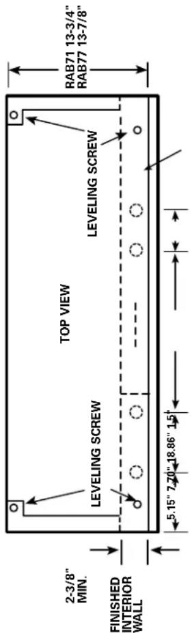
text_image
2-3/8" MIN. FINISHED INTERIOR WALL TOP VIEW LEVELING SCREW LEVELING SCREW RAB71 13-3/4" RAB77 13-7/8" 5.15" 7.70" 18.86" 1.5"
text_image
BACK VIEW 5.15" 7 20" 8.80" 10.30" SIDE VIEW WITH WALL CASE SHOWN IN PLACE RAB71 16" RAB77 16-1/4" 3" MIN. ADJUSTABLE TO 5" 1-5/16" 2-3/8" INTERIOR WALL 1-1/2" 7/8" FINISHED FLOOR RECOMMEND 2" TO INTERIOR ADJACENT WALL BOTH SIDES. D 42" D FRONT VIEW SEE NOTE LEFT SIDE INTERIOR ADJACENT WALL 12-3/4" 12-7/8" LEVELING SCREW KNOCKOUTS (ENCLOSURE) 4 REAR; 4 BOTTOM KNOCKOUT SIZE LARGE 1-1/8" DIA. SMALL 7/8" DIA. MAX. WALL THICKNESS CAULK* C A *Caulk around perimeter of wall case all four sides where it joins the building - Interior and Exterior. MOUNTING SCREWS AND HOLES BY INSTALLER ROOM CABINET 3-11/16" 2-3/8" MIN. CASE EDGE TO FINISHED WALL CAULK* FINISHED FLOOR LEVELING SCREWS (2) SUB-BASE BODY (2) SIDE EXTENSIONS CONDUIT ENTRY (ALTERNATES) SIDE VIEW RAB71 16" RAB77 16-1/4" B CAULK* Caulk*RAK204 SERIES SUB-BASE INSTALLATION AND ELECTRICAL DATA
RAB71/77 Wall Case

text_image
5/32" DIA. HOLE (SEE NOTE) FOR SECURING TYPE "D" CLIPS TO SLEEVE USING TYPE "A" SCREWS 6" 6" GREEN GROUND SCREW (TYPE "C") METAL CASE TYPE "B" SCREW SCREW CLIP TYPE "D" TYPE "A" SCREW TO SECURE SIDE CHANNELS TYPE "A" SCREW TYPE "C" SCREW ACCESS PLATES SIDE CHANNELS ARE ADJUSTABLE FROM 13-3/4" TO 2-3/8" IN LENGTH BY BREAKING OFF SECTIONS OF SIDE CHANNELS. NOTE: IF METAL CASE DOES NOT HAVE SCREW HOLES, 5/32" DIA. HOLES MUST BE DRILLED 6" FROM EACH SIDE IN FRONT FLANGE. (SEE INSERT). CHASEWAY OPTION (Shown Without Chassis and Wall Case for Installation Location Only.) RAK4002B NOTE: TYPE "E" MOUNTING CLIP MUST BE USED WITH MOLDED CASE. MOLDED CASE SUB-BASE MOUNTING CLIP TYPE "E" TYPE "A" TYPE "B" TYPE "C" 6 REQ'D. 2 REQ'D. 8 REQ'D. TYPE "D" TYPE "E" USE WITH RAB71 USE WITH RAB77Electrical wiring may enter the sub-base through any of the knockout holes provided in the sub-base. Knockout holes in the sub-base access plate may accommodate a receptacle, which allows the use of a power cord (if permitted by code for the particular installation). A knockout for a circuit breaker, fuseholder or a disconnect is also provided. See pages 22 and 23 for description of electrical contents of these sub-bases.
Condensate Disposal Systems
Cooling Condensate
Air conditioners produce condensate water as a result of lowering the humidity of the area being conditioned. When the indoor coil temperature is below the dew point, moisture in the air condenses into water droplets on the coil. This water drains to a pan located under the indoor coil and is routed through the barrier, the partition separating the indoor and outdoor sides of the unit, to the base pan on the outdoor side. It is then picked up and dispersed against the outdoor coil, which is hot when the unit is in the air conditioning mode. The water is evaporated into the atmosphere by contact with the hot outdoor coil. This evaporation process also helps lower the temperature of the outdoor coil and improves the operating efficiency of the unit.
Slinger Ring Systems
Packaged terminal units employ various means of dispersing the condensate water. One of the most popular, and most effective, means is by the use of a "slinger ring." A slinger ring is a ring around the circumference of the outdoor fan. The design of the unit positions the slinger ring very close to the bottom of the base pan so water in the base pan is lifted by the rotating ring. Water picked up by the slinger ring will be dispersed into the air stream and deposited on the hot outdoor coil where it evaporates.
All Zoneline ^® Series packaged terminal air conditioners and packaged terminal heat pumps utilize a slinger ring for cooling condensate disposal.
Certification Test Requirements
ARI (Air Conditioning & Refrigerating Institute) requires that all certified packaged terminal air conditioners and packaged terminal heat pumps pass a cooling condensate disposal test. One stipulation of the ARI test is that "the test start with condensate collection pan brimful." In order to pass the ARI Condensate Disposal Test the unit must operate continuously for four hours without condensed water blowing, dripping, or running off the unit casing during the test or after the unit has been turned off. Under extremely high outdoor humidity conditions or extreme operating conditions, such as exceptionally high air infiltration (a door or window left open while the unit is running, for instance) it is possible for any air conditioner to be unable to dissipate all the cooling condensate generated.
All Zoneline Series packaged terminal air conditioners and packaged terminal heat pumps meet the condensate disposal requirements of ARI standards 310-93 and 380-93.
Heat Pump Condensate
During the operation of a unit in the heat pump, or "reverse cycle," mode the outdoor coil becomes the cold coil and the indoor coil becomes the hot coil due to reversing the flow of the refrigerant. When the temperature of the outdoor coil is below the dew point, condensation will form on the outdoor coil just as it does on the indoor coil during cooling operation. Since the dew point is humidity- as well as temperature-related, there may be more condensate on days when the relative humidity is high.
Heat Pump Condensate Disposal
Since the outdoor coil is cold during heat pump operation, the condensate water cannot be deposited on the outdoor coil as the water would cause frost to form on the coil. This frost would block the airflow through the coil and greatly reduce the outdoor air. Rather than allow this problem to occur, heat pump units must dispose of the condensate in another manner.
Temperature-Activated Drain Valve

natural_image
Close-up of a mechanical component with threaded shaft and mounting bracket (no visible text or symbols)The most widely used method of disposing of heat pump condensate is with a temperature-activated drain valve. This is a device mounted in the base pan of a heat pump unit with a bellows that expands on temperature rise and contracts with temperature drop. A shaft with a rubber plug on the end is connected to the bellows. When the outdoor temperature remains
above a certain temperature, the bellows is expanded and the plug fits tightly into a hole in the bottom, or base pan, of the unit. When the plug is blocking the hole, as it should be during cooling operation, the condensate water is contained in the base pan. At temperatures when heating is required, the bellows contracts, the rubber plug is retracted from the hole and the heat pump condensate water is allowed to drain into the wall case. The valve is fully open at 45^ F.
Drain Kits
Although the Zoneline units are designed to dissipate all the condensate generated during normal cooling operation, there may be times when abnormal operating conditions cause more condensate than the unit can dissipate. Heat pumps also generate condensate that the unit may not be designed to dissipate. For these reasons, if condensate dripping from the wall case is objectionable, an internal or external drain system should be installed. See pages 35 and 36 for information covering the drain systems and the RAD10 kit available to connect to the wall case.
Internal Condensate Removal (ICR) System
GE has developed an Internal Condensate Removal (ICR) system for packaged terminal heat pumps. This system has been offered as an option on Zoneline packaged terminal Heat Pumps since 1982, and thousands of them are in use. During heat pump operation the ICR system utilizes a small pump to lift the water from the base pan and pump it into a collector tray positioned above the indoor coil. The water drains from the collector tray and drips onto the warm indoor coil where it is evaporated into the room atmosphere. If an excess amount of water is pumped to the indoor side, it is routed back to the outdoor portion of the base pan.
The ICR system has proven to be an effective means of minimizing the amount of heat pump condensate dripping from the unit. However, if the restrictions of a particular installation will allow absolutely no drippage of condensate water from the wall case, the installation of an internal or external drain system is recommended.
Units with ICR may not be installed in seacoast or corrosive environment applications.
WALL CASE WITH RAD10 DRAIN KIT
External Drain. See page 36 for internal drain.
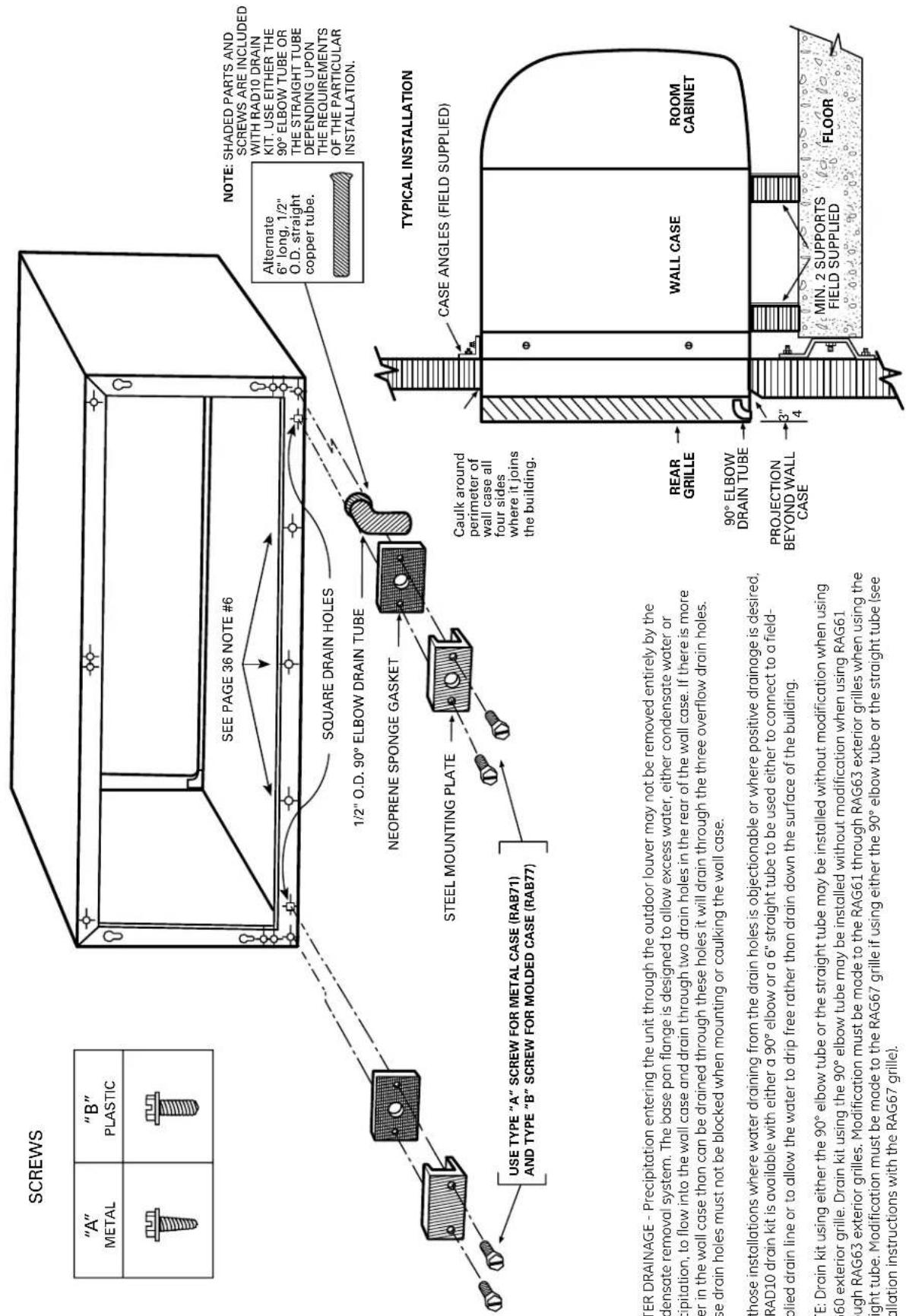
text_image
SCREWS "A" METAL "B" PLASTIC SEE PAGE 36 NOTE #6 SQUARE DRAIN HOLES Alternate 6" long, 1/2" O.D. straight copper tube. NOTE: SHADED PARTS AND SCREWS ARE INCLUDED WITH RAD10 DRAIN KIT. USE EITHER THE 90° ELBOW TUBE OR THE STRAIGHT TUBE DEPENDING UPON THE REQUIREMENTS OF THE PARTICULAR INSTALLATION. NEOPRENE SPONGE GASKET STEEL MOUNTING PLATE TYPICAL INSTALLATION CASE ANGLES (FIELD SUPPLIED) CAULK around perimeter of wall case all four sides where it joins the building. USE TYPE "A" SCREW FOR METAL CASE (RAB71) AND TYPE "B" SCREW FOR MOLDED CASE (RAB77) CRAILK AROUND perimeter of wall case all four sides where it joins the building. WALL CASE ROOM CABINET REAR GRILLE 90° ELBOW DRAIN TUBE PROJECTION BEYOND WALL CASE 3" 4" MIN. 2 SUPPORTS FIELD SUPPLIED FLOOR TER DRAINAGE - Precipitation entering the unit through the outdoor louver may not be removed entirely by the densate removal system. The base pan flange is designed to allow excess water, either condensate water or cipitation, to flow into the wall case and drain through two drain holes in the rear of the wall case. If there is more ther in the wall case than can be drained through these holes it will drain through the three overflow drain holes. se drain holes must not be blocked when mounting or caulking the wall case. those installations where water draining from the drain holes is objectionable or where positive drainage is desired, RAD10 drain kit is available with either a 90° elbow or a 6" straight tube to be used either to connect to a field- plied drain line or to allow the water to drip free rather than drain down the surface of the building. TE: Drain kit using either the 90° elbow tube or the straight tube may be installed without modification when using 660 exterior grille. Drain kit using the 90° elbow tube may be installed without modification when using RAG61 ough RAG63 exterior grilles. Modification must be made to the RAG61 through RAG63 exterior grilles when using the light tube. Modification must be made to the RAG67 grille if using either the 90° elbow tube or the straight tube (see allation instructions with the RAG67 grille).WATER DRAINAGE - Precipitation entering the unit through the outdoor louver may not be removed entirely by the condensate removal system. The base pan flange is designed to allow excess water, either condensate water or precipitation, to flow into the wall case and drain through two drain holes in the rear of the wall case. If there is more water in the wall case than can be drained through these holes it will drain through the three overflow drain holes. These drain holes must not be blocked when mounting or caulking the wall case.
For those installations where water draining from the drain holes is objectionable or where positive drainage is desired, the RAD10 drain kit is available with either a 90° elbow or a 6" straight tube to be used either to connect to a field-supplied drain line or to allow the water to drip free rather than drain down the surface of the building.
NOTE: Drain kit using either the 90° elbow tube or the straight tube may be installed without modification when using RAG60 exterior grille. Drain kit using the 90° elbow tube may be installed without modification when using RAG61 through RAG63 exterior grilles. Modification must be made to the RAG61 through RAG63 exterior grilles when using the straight tube. Modification must be made to the RAG67 grille if using either the 90° elbow tube or the straight tube (see
installation instructions with the RAG6/ grille).
WALL CASE WITH RAD10 DRAIN KIT
Internal Drain. See page 35 for external drain.
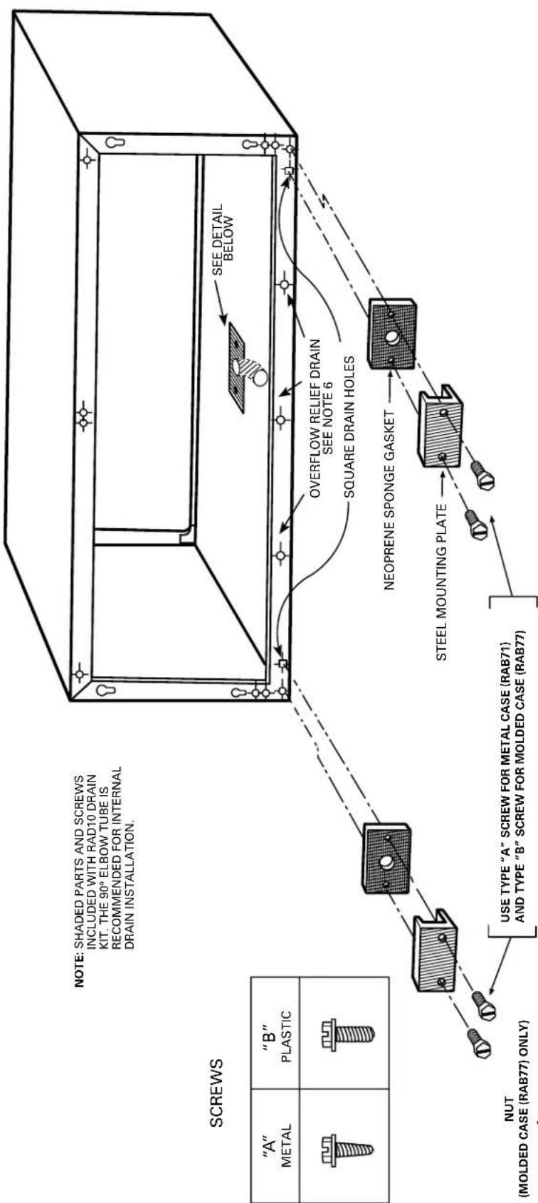
text_image
NOTE: SHADED PARTS AND SCREWS INCLUDED WITH RAD10 DRAIN KIT. THE 90° ELBOW TUBE IS RECOMMENDED FOR INTERNAL DRAIN INSTALLATION. SEE DETAIL BELOW OVERFLOW RELIEF DRAIN SEE NOTE 6 SQUARE DRAIN HOLES NEOPRENE SPONGE GASKET STEEL MOUNTING PLATE NUT (MOLDED CASE (RAB77) ONLY) USE TYPE "A" SCREW FOR METAL CASE (RAB71) AND TYPE "B" SCREW FOR MOLDED CASE (RAB77)- The RAD10 drain kit is installed in the bottom of the wall case when it is desired to drain
condensate to an internal drain system in the building. - The drain kit is mounted on the bottom of the wall case prior to installation of the case in the
wall. It may be located anywhere on the room-side portion except for sub-base installations.
For these the drain should be at least 3" from the indoor edge of the case so as to adequately clear the sub-base. - A template is furnished with the kit for locating the necessary three holes in the case bottom
—two to provide a securing means and one to provide a drain hole for the 1/2" OD tubing
(see details at left). - A tube or hose 1/2" I.D. (obtained locally) must be installed on the drain tube and connected to the internal drain system in the building.
- With the RAD10 the two square drain holes in the bottom outer flange of the wall case are
- With the RAD10 the two square drain holes in the bottom outer range of the wall case are sealed by the gaskets and mounting plates shown above.
- Three (3) 1/2" diameter holes located 1/4" above the case bottom in the bottom outer flange
provide overflow drainage to the outdoors when wind-driven rain enters the chassis.
USE TYPE "A" SCREWS FOR BOTH RAB71 AND RAB77
Ducted Installations
2900 and 3900 Series Zoneline®units may be used in ducted installations.
With a ducted installation it is possible to condition the air in two areas that have a common wall separating them. A special adapter mounts on the wall case and a transition piece directs the air from the unit into the adapter. Instructions for mounting the adapter to the wall case are included with the duct adapter. The adapter contains a grille that allows air from the unit to be discharged into the primary room and the adapter connects to a duct extension that allows the air to flow to the adjoining room. Ducting a unit may allow a single unit to be used rather than a separate unit in each room, providing a means of reducing initial equipment cost. The duct may extend a total of 15 feet (with a field-fabricated insulated duct extension) in one direction, either to the right or to the left of the unit. A baffle in the adapter allows up to 50% of the discharge air to be delivered to the secondary room.
The installation of the wall case and sub-base, if used, is the same for units being ducted as for free-standing units. The duct adapter support bracket overlaps the wall case by 1" and the bracket and mounting screws add approximately 3/8" (3/16" on each side) to the width of the wall case. If less than 1" of the wall case projects into the room it will be necessary to allow for the additional width in the opening for the wall case. The duct adapter mounting brackets should be mounted prior to installing the case in the wall.
Refer to pages 38 and 39 for drawings of ducted installations.
Prior to the installation of the transition from the room cabinet to the adapter, it will be necessary to remove the discharge grille from the room cabinet. Instructions for this modification are included with the duct adapter.
New Ducted Installations
Components
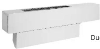
natural_image
White rectangular object with a black top opening, possibly a printer or scanner (no visible text or symbols)Duct Adapter RAK6052
Duct Adapter RAK6052 — The duct adapter is secured to each side of the wall case and requires the drilling of mounting holes in the wall case during installation. A template for the hole location is in the installation instructions. By securing the duct adapter to the wall case, the chassis retains the slide-out feature for servicing after the transition piece is removed.
Duct Extension RAK601 — This kit contains a 44"-long insulated duct, a register mounting collar, and an air supply register. It can be secured to the duct adapter at either end of the adapter. This duct may be cut at any dimension and used in two applications providing the sum of the two duct lengths necessary does not exceed the 44" length. Even in single applications the mounting flange must be cut off one end of the duct to accept the collar and supply register.
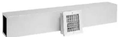
natural_image
Exterior view of a white rectangular industrial ventilation unit with a central gridded fan (no text or symbols visible)RAK601 Duct Extension, Mounting Collar and Register
Mounting Collar and Supply Register RAK602 —These components are included in the Duct Extension Kit RAK601. They may be ordered separately for installations where two duct extensions are made from one RAK601.
Ducted Application Considerations
When designing a ducted application, some application considerations to be made include:
- Do not exceed the 15-foot-length maximum for the duct extension. Field-supplied duct extension must be completely insulated with minimum of 1/2" insulation
- The duct must be a straight run. Turns or bends in the duct extension create air pressure drops that the unit is not designed to overcome.
- Minimum recommended clearance between the unit and the adjacent wall is 2".
- Provisions for return air must be made to allow air circulation from secondary room. Doors in both secondary and primary rooms may be undercut or a return grille may be installed through a common wall.
- When calculating the heat gain/heat loss take both areas into consideration.
Replacements of Existing Ducted Units
Since the design of the Zoneline chassis has changed over the years to provide better performance and appearance, some of the components used in ducted applications have changed. Select the proper components from the information below. The best procedure in determining the correct kit is to measure duct extension cross section.
Flat-Top Discharge Units (Zoneline Units Built Prior to 1988)
Existing Duct Extension Cross Section Measurements: 8-3/8" height x 6-1/2" width
Duct Adapter RAK7012 — This duct adapter will allow the replacement of a new chassis (2900 or 3900 Series unit) into an existing ducted application. This adapter will align properly with the duct extension and will eliminate the need to modify the wall opening. In order to minimize replacement costs, some of the components of the old duct adapter must be removed and used in the new installation. Consult the Installation Instructions of the RAK7012 before removing and discarding the old duct adapter. See additional notes page 58.
Slope-Front Discharge Units
(Models With AZC, AZR, AZW, or AZ21 or AZ31 Prefix)
Existing Duct Extension Cross Section Measurements: 7-3/32" height x 6-1/2" width
Duct Transition RAK7022 — This duct transition will allow the replacement of a new slope-front discharge Zoneline chassis (2900 or 3900 Series unit) into a previous-design slope-front ducted installation. See additional notes page 58.
DUCTED APPLICATION (AZ2800/2900/3800/3900 SERIES)
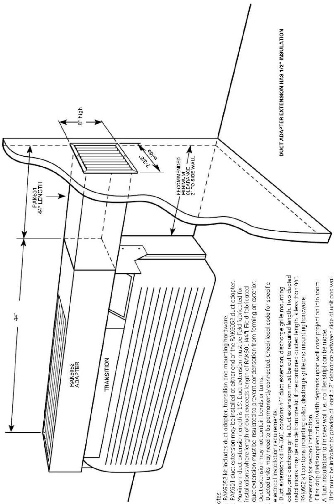
text_image
44" RAK601 44" LENGTH RAK6052 ADAPTER 8" high TRANSITION 7-3/8" wide RECOMMENDED MINIMUM CLEARANCE 2" TO SIDE WALL DUCT ADAPTER EXTENSION HAS 1/2" INSULATION Notes: . RAK6052 kit includes duct adapter, transition and mounting hardware. . RAK601 duct extension may be installed at either end of the RAK6052 duct adapter. Maximum duct extension length is 15'. Duct extension must be field fabricated for installations where length of duct exceeds length of RAK601 (44"). Field-fabricated duct extension must be insulated to prevent condensation from forming on exterior. Duct extension may not contain bends or turns. . Ducted units may need to be permanently connected. Check local code for specific electrical installation requirements. . Duct extension kit RAK601 contains 44" duct extension, discharge grille mounting collar, and discharge grille. Duct extension must be cut to required length. Two ducted installations may be made from one kit if the combined ducted length is less than 44". RAK602 kit contains mounting collar, discharge grille and mounting hardware necessary for second installation. . Filler strip (field supplied) actual width depends upon wall case projection into room. A flush installation to finished wall (i.e., no filler strip) can be made. . Unit must be installed to provide at least a 2" clearance between side of unit and wall.Notes:
1. RAK6052 kit includes duct adapter, transition and mounting hardware.
2. RAK601 duct extension may be installed at either end of the RAK6052 duct adapter.
Maximum duct extension length is 15'. Duct extension must be field fabricated for
installations where length of duct exceeds length of RAKb01 (44"). Field-fabricated duct extension must be insulated to prevent condensation from forming or outer
duct extension must be insulated to prevent condensation from forming on exterior. Duct extension may not contain bonds or turns.
3. Ducted units may need to be permanently connected. Check local code for specific
3. Bucted units may need to be permanently connected. Check local code for specific electrical installation requirements.
4. Duct extension kit RAK601 contains 44" duct extension, discharge grille mounting
collar, and discharge grille. Duct extension must be cut to required length. Two duct
installations may be made from one kit if the combined ducted length is less than 44
RAK602 kit contains mounting collar, discharge grille and mounting hardware
necessary for second installation.
5. Filler strip (field supplied) actual width depends upon wall case projection into room. A flush installation to finished wall (i.e., no filler strip) can be made.
6. Unit must be installed to provide at least a 2" clearance between side of unit and wa
7. Provisions for return air must be made in order to allow air circulation from seconda
1. Provisions for return for must be made in order to show all circulation from second floor. Doors in both secondary and primary rooms may be undercut or a return grille
may be installed through common wall.
8. For replacement of previous-design units, see pages 37 and 58.
DUCTED DETAILED SIDE VIEWS (AZ2800/2900/3800/3900 SERIES)
See page 38 for all notes
Sub-Base Installation
Line Cord Installation
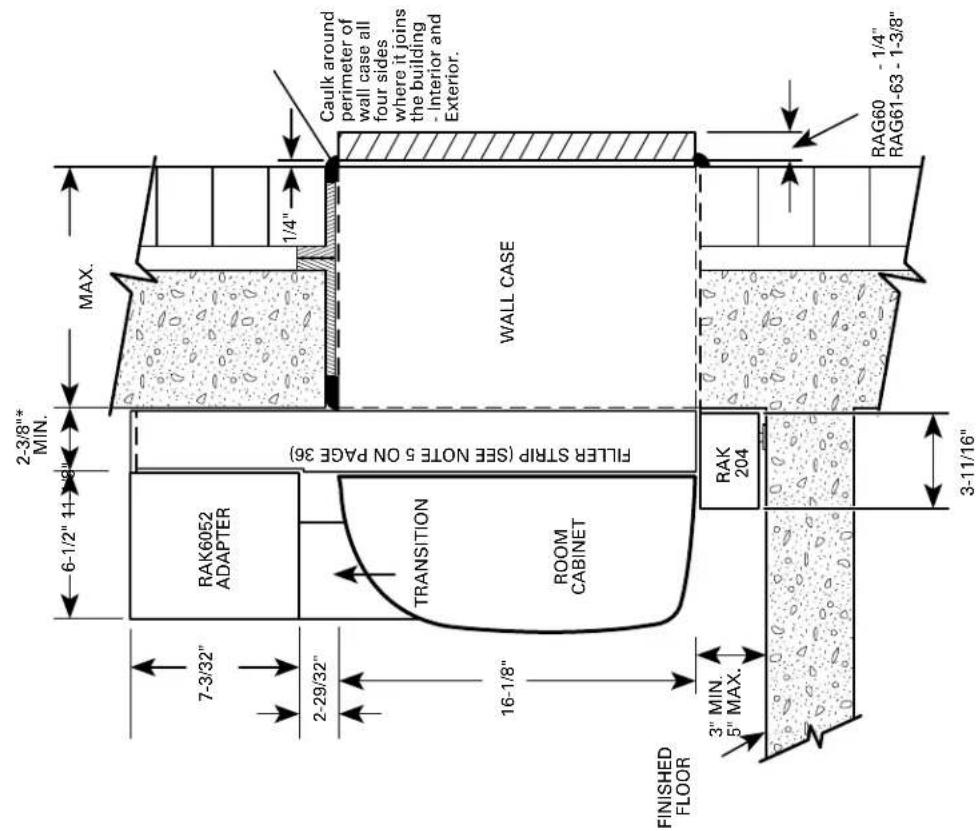
text_image
2-3/8"* MIN. 6-1/2" 11" 9" MAX. 7-3/32" 2-29/32" TRANSITION FILLER STRIP (SEE NOTE 5 ON PAGE 36) ROOM CABINET 16-1/8" FINISHED FLOOR 3" MIN. 5" MAX. RAK6052 ADAPTER Caulk around perimeter of wall case all four sides where it joins the building - Interior and Exterior. RAK 204 3-11/16" RAG60 - 1/4" RAG61-63 - 1-3/8"*2-3/8" min. when installed with RAK204.
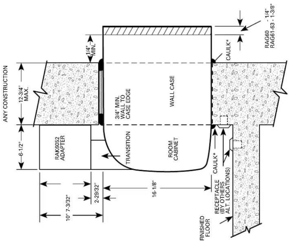
text_image
ANY CONSTRUCTION 6-1/2" 12-3/4" MAX. 10" 7-3/32" 2-29/32" 1/4" MIN. TRANSITION 3/4" MIN. WALL TO CASE EDGE ROOM CABINET WALL CASE FINISHED FLOOR RECEPTACLE (BY OTHERS ALT. LOCATIONS) CAULK* CAULK* RAG60 - 1/4" RAG61-63 - 1-3/8"*Caulk around perimeter of wall case all four sides where it joins the building - Interior and Exterior.
Exterior Grilles
Four styles of outdoor grilles are available for exterior treatments. The standard stamped aluminum grille (RAG60), the molded architectural louvered exterior grilles (RAG61-63) and the extruded aluminum architectural louvered grille (RAG67). All grilles include air deflectors and gaskets to prevent condenser air recirculation.
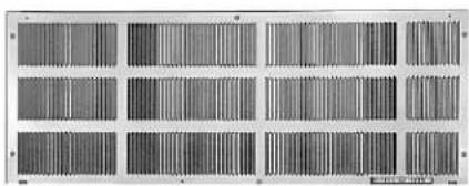
natural_image
Grid of grayscale rectangular panels with vertical striations, no text or symbols visibleRAG60 Outdoor Grille
RAG60 Outdoor Grille — The standard exterior grille is made of durable aluminum to protect chassis components and prevent air recirculation.

natural_image
Close-up of a white ventilation grille with grid patterns and a magnified inset showing detailed texture (no text or symbols)RAG61 Outdoor Grille
RAG61, 62, 63 Architectural Grille — One-piece optional molded grille and frame assembly provides improved appearance, protection and weatherability. Molded of durable polycarbonate, the surfaces of the grille have a colorfast, slightly textured finish which blends well with most types of wall surfaces. The grilles can be painted in the field to match the building for improved aesthetics.
Colors: RAG61 — Beige
RAG62 — Dark Maple
RAG63 — Bittersweet Chocolate

natural_image
Exterior view of a corrugated metal panel with horizontal grooves (no text or symbols)RAG67 Extruded Aluminum Grille — The RAG67 is made from extruded anodized aluminum for use where an aluminum architectural grille is preferred. The RAG67 is available in a clear finish and may be special ordered from GE in other colors. Minimum order quantities may be required. Contact your General Electric salesperson for details.
All grilles are installed and secured to the wall case from the inside. Keyhole slots in the rear flange of the case allow the grille to be placed in position before securing it firmly to the wall case.
Replacement of existing units: If an existing grille is not replaced, capacity and efficiency will be reduced and the unit may fail to operate properly or fail prematurely. A deflector kit, RAK40, may be used with grilles that were not designed for current AZ Series GE Zoneline® units. The RAK40 contains air deflectors and gaskets that mount to the chassis to direct the hot exhaust air away from the air intake to allow the unit to function properly. All grilles used with GE Zoneline units must comply with requirements of Exterior Architectural Treatments and Special Outdoor Grilles as follows.
Exterior Architectural Treatments and Special Outdoor Grilles
The architectural design of a building may dictate the use of special or oversized louvers for aesthetic reasons. Louvers other than standard Zoneline exterior grilles may be used on the Zoneline unit, however, these special louvers, or any special exterior architectural treatments of the building facade that may restrict the free circulation of condenser airflow, should be referred to GE Application Engineering for evaluation and approval. The following guidelines should be followed in selecting a louver:
- The louver must have a minimum of 65% free area.
ASHRAE defines free area as the minimum area of the opening in an air inlet or outlet through which air can pass. Percent (%) free area equals the X dimension divided by the Y dimension. - The louver should be attached to the wall case in a manner that will prevent recirculation of condenser discharge air into the air inlet. If the louver is not attached directly to the wall case, a field-supplied splitter or gasket is required between the chassis and the louver to prevent recirculation.
It is important that the above criteria be followed since a louver that is too restrictive or allows recirculation will reduce the unit's capacity and efficiency, increase the electrical current draw, cause intermittent operation due to the compressor overload protector shutting the compressor off, and cause failure of the compressor overload and shorten compressor life. Using the unit with a grille that is too restrictive or allows recirculation may constitute improper installation and will void the unit's warranty.
A scale drawing of the louver section should be sent to GE Application Engineering. To assure the proper performance of the Zoneline unit and comply with Underwriters Laboratories requirements, it may be necessary to send a sample louver section (at least 16" x 42") to an independent lab to be tested with the Zoneline unit.
$$ \begin{array}{c} \hline \text {Sample Calculations} \ \text {Free Area (\%)} = \frac {x}{y} \times 1 0 0 \quad x = 1" \quad y = 1. 5" \ \text {F.A. \%} = \frac {1}{1 . 5} \times 1 0 0 = 6 6. 7 \% \ \hline \end{array} $$
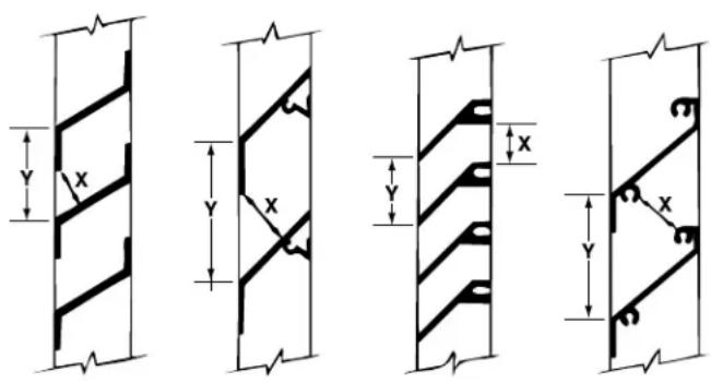
text_image
Technical diagram showing four different structural cross-sections with dimension labels 'X' and 'Y' indicating height measurements.Power Connection for 2900, 3900 and 5800 Series Zoneline® Units
All 2900, 3900, and 5800 Series Zoneline units are equipped with universal heaters allowing chassis installation flexibility. The Zoneline units are connected to the building power supply by a unique power connection kit. By utilizing a separate universal power connection (UPC) kit, each unit is capable of providing various outputs of electric resistance heat to more closely meet the heating requirements of the particular room, thereby increasing the installation flexibility of the particular chassis. This power connection kit is the only means of supplying power to the Zoneline chassis. The appropriate kit is determined by the voltage, the means of electrical connection, either line-cord connected or permanently connected, and the desired resistance heat output that may be supported by the branch circuit.
230/208-Volt Line-Cord Connected Units
Line Cord Kits consist of a self-aligning nine-pin molded connector that plugs into a mating connector on the Zoneline chassis and insulated line cord with an electrical plug on the end. The configuration of the electrical plug conforms to NEC standards for the circuit amperage and the position of the wires in the nine-pin connector determines the heater wattage and current requirements when it is plugged into the Zoneline chassis.
The power connection kit is selected by the amperage of the circuit where it will be installed. Each line cord kit has an integral Leakage Current Detection and Interruption (LCDI) or Arc Fault Current Interrupter (AFCI) device as required by the National Electrical Code (NEC) and Underwriters Laboratory (UL) for line-cord connected air conditioners manufactured on or after August 1, 2004. The line-cord power connection kits are shown in the table below.
230/208-Volt Line-Cord Connected Units
| Line Cord Kit | Electric Heat BTUH | Electric Heater Watts | Electric Heat Amps | Min. Circuit Protection (Amps) |
| RAK3153 8600/7100 2550/2090 11.6/10.6 15 | ||||
| RAK3203 | 11700/9600 3450/2820 15.5/14.2 20 | |||
| RAK3303 17000/13900 | 5000/4090 22.4/20.4 30 | |||
Electric Heat Amps include electric heater and fan motor current draw.
230/208-Volt Permanently Connected Units
Permanently connected units do not require the LCDI or AFCI device. Permanent connection is usually made through the use of a sub-base. Each 230/208-volt sub-base consists of a sub-base with appropriate receptacle for minimum circuit amperage, a chaseway to route power connector from the sub-base to the chassis, wiring to connect the sub-base to building wiring and a short line cord with a self-aligning nine-pin connector to connect to chassis and plug into the receptacle in the sub-base. Permanent, or direct-wired, installation of a 230/208-volt unit requires a junction box kit, RAK4002A, which attaches to the chassis to form an enclosed junction box.
The short sub-base line cord may not be used without the sub-base.
For 2900 and 3900 Series 230/208-volt units where a permanent installation using flexible conduit is desired, the RAK4002A forms an enclosed junction box on the chassis. The RAK4002A has a 7/8"-diameter hole to allow conduit to be connected to the junction box. For direct connection, purchase and install the appropriate Universal Power Supply Kit (also referred to as the Direct Connection Kit below) that matches the ampacity of the building circuit connected to the unit. This nine-pin connector with three 7"-long conductor wires is used for direct connections to the building wiring inside a direct-connect junction box. These wires are then connected to the building wiring by field-supplied connectors.
For 5800 Series 230/208-volt units, the permanent installation using flexible conduit procedure is the same as for the 2800 and 3800 Series units, except the junction box kit is RAK4002B.
230/208 Volt Sub-Base and Direct-Connected Units
| Sub-Base | Direct Connection Kit | Electric Heat BTUH | Electric Heater Watts | Electric Heat Amps | Min. Circuit Protection (Amps) |
| RAK204D15P | RAK4157 | 8600/7100 | 2550/2090 | 11.6/10.6 | 15 |
| RAK204D20P | RAK4207 | 11700/9600 | 3450/2820 | 15.5/14.2 | 20 |
| RAK204D30P | RAK4307 | 17000/13900 | 5000/4090 | 22.4/20.4 | 30 |
Electric Heat Amps include electric heater and fan motor current draw.
265- or 277-Volt Unit Installation — Permanently Connected Units
National Electric Code (Article 440.60) requires permanent connection for units connected to power sources over 250 volts; therefore these units must be permanently connected (direct-wired) with field-supplied connectors. Units connected using a sub-base meet the requirement for permanent connection since all wiring is internal wiring between the sub-base and the chassis.
Since 265-volt units may not be line-cord connected, an LCD device is not required.
265 Volt Sub-Base and Direct-Connected Units
| Sub-Base | Power Connection Kit | Direct Connection Kit | Electric Heat BTUH | Electric Heater Watts | Electric Heat Amps | Min. Circuit Protection (Amps) |
| RAK204E15 | RAK5172 RAK | 5157 8600 25 | 50 10.3 15 | |||
| RAK204E20 | RAK5202 RAK | 5207 11700 | 3450 13.8 20 | |||
| RAK204E30 | RAK5302 RAK | 5307 | 17000 | 5000 19.6 30 |
Electric Heat Amps include electric heater and fan motor current draw. Each 265-volt sub-base kit consists of a sub-base with appropriate receptacle for minimum circuit amperage, a chaseway to route the power connector from the sub-base to the chassis and wiring to connect the sub-base to the building wiring.
The 265-volt power connection kit must be ordered separately.
All wiring must conform to local electrical regulations and codes.
Essential Elements Ordering Overview
230/208-volt line-cord connected units — order line cord kit. 230/208-volt sub-base connected units — order sub-base (includes power connection kit) and junction box for chassis. 265-volt units — order sub-base and power connection kit separately.
Electrical Wiring Information - 2900/3900/5800 Series
All Zonelines are single-phase 60 hertz units.
For all installations, the feeder, sub-feeder, branch circuit and electrical protective devices and selection must conform to the National Electrical Code and to local codes.
Maximum connected load in amperes, including demands for the electric heater and the fan motor, are shown on page 44. Branch circuit ampacity and electrical protective device sizing are shown on page 42 for 230/208-volt and for 265-volt units.
More than one unit per branch circuit is not recommended. When in doubt, consult the National Electrical Code. All wiring, including installation of receptacle, must conform to local electrical regulations and codes.
Replacement of Existing Chassis
230/208-Volt and 265-Volt Units
There have been changes to NEC and improvements and modifications to the Zoneline chassis and sub-bases since the unit was first introduced. Some of these changes require alterations to be made when replacing an older unit with a new chassis.
Line-Cord Connected Units
The plug configuration of new line-cord connected units complies with the current NEC standards. Older installations may have wall receptacles that conformed to NEC standards at the time the building was constructed and may not match the configuration of the plug on the new line cord. The recommended solution is to change the wall receptacle to conform to current standard plug configuration. See chart on this page for current receptacle configuration.

natural_image
Coiled white medical or electrical device with two connectors (no text or symbols visible)Typical Line-Cord Power Connection Kit RAK3203 shown
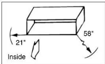
text_image
21" Inside 58"Maximum Cord Extension
Permanently Connected Units With Sub-Base
If the existing unit is connected to a sub-base, the installation of the new unit may involve modifying the existing installation slightly. It is recommended these modifications be made by a qualified electrician.
If the existing sub-base is the full width of the wall case, RAK201 sub-base access plate may be ordered and used to replace the cover on the old sub-base. Field-supplied wiring, conduit and conduit connectors should be used to make a connection between the new chassis and the center knockout of the RAK201. The wiring connections should be made inside the sub-base and the RAK201 attached to the sub-base with the two screws provided.
If the existing sub-base is not the full width of the wall case, the electrician will have to modify the existing cover plate to allow field-supplied wiring, conduit and conduit connectors to be run from the permanent connection kit to the sub-base.
text_image
LEMONS POWER & AIR CAPS FOR ALL 20% ON THE AIR CAPS HEAT CONTINUING DUCTURE, INLET, RATE 2. WIRE COOKING TO BE PEELED FOR BEANS FLOWING TO COLDING AIR CAPS BEANS HOLDING TO BANANA AIR CAPS BEANS HOLDING TO COLDING AIR CAPS BEANS HOLDING TO BANANA AIR CAPS BEANS HOLDING TO COLDING AIR CAPS BEANS HOLDING TO BANANA AIR CAPS BEANS HOLDING TO COLDING AIR CAPS BEANS HOLDING TO BANANA AIR CAPS BEANS HOLDING TO COLDING AIR CAPS BEANS HOLDING TO BANANA AIR CAPS BEANS HOLDING TO CREDING AIR CAPS BEANS HOLDING TO BANANA AIR CAPS BEANS HOLDING TO COLDING AIR CAPS BEANS HOLDING TO BANANA AIR CAPS BEANS HOLDING TO COLDING AIR CAPS BEANS HOLDING TO BANANA AIR CAPS BEANS HOLDING TO COLDING AIR CAPS BEANS HOLDING TO BANANA AIR CAPS BEANS HOLDING TO COLDING AIR CAP S BEANS HOLDING TO BANANA AIR CAP S BEANS HOLDING TO COLDING AIR CAP S BEANS HOLDING TO BANANA AIR CAP S BEANS HOLDING TO COLDING AIR CAP S BEANS HOLDING TO BANANA AIR CAP S BEANS HOLDING TO COLDING AIR CAP S BEANS HOLDING TO BANANA AIR CAP S BEANS HOLDING TO COLDING AIR CAP S BEANS HOLDING TO BANANA AIR CAP S BEANS LOADS BEANS LOADS BEANS LOADS BEANS LOADS BEANS LOADS BEANS LOADS BEANS LOADS BEANS LOADS BEANS LOADS BEANS LOADS BEANS LOADS BEANS LOADS BEANS LOADS BEANS LOADS BEANS LOADS BEANS LOADS BEANS LOADS BEANS LOADS BEANS LOADS BEANS LOADS BEANS LOADs BEANS loads BEANS loads BEANS loads BEANS loads BEANS loads BEANS loads BEANS loads BEANS loads BEANS loads BEANS loads BEANS loads BEANS loads BEANS loads BEANS loads BEANS loads BEANS loads BEANS loads BEANS loads BEANS loads BEANS loads BEANS loadsEnclosure cover removed.
RAK4002A
Wiring harness can be ordered separately as RAK4002CW.
Receptacle
| Type Mfg Part No Configuration | |||
| 15 AMP Tandem NEMA6-15R | Hubbell P&S | 5661 5661 |  |
| 20 AMP Perpendicular NEMA6-20R | Hubbell P&S | 5461 5871 |  |
| 30 AMP Large Tandem NEMA6-30R | Hubbell P&S | 9330 5930 |  |
Maximum Connected Load
The maximum connected load of a Zoneline® unit occurs when the unit is in resistance heating operation. The maximum amperage shown in the tables below is the combined total of the resistance heater and the indoor fan motor.
230/208-Volt Line-Cord Connected Units
| Power Connector Kit | ||||||
| RAK3153RAK4157RAK204D15P | RAK3203RAK4207RAK204D20P | RAK3303RAK4307RAK204D30P | ||||
| MODEL NUMBER | 230 V 208 V 230 V 208 V 230 V 208 V | |||||
| AZ29E07DA* 11.5 | 10.5 15.5 14.1 N/A N/A | |||||
| AZ29E09DA* 11.5 | 10.5 15.5 14.1 22.3 20.3 | |||||
| AZ29E12DA* 11.6 | 10.6 15.5 14.1 22.3 20.3 | |||||
| AZ29E15DA* 11.6 | 10.6 15.6 14.2 22.4 20.4 | |||||
| AZ39H07DA* | 11.5 10.5 15.5 | 14.1 N/A N/A | ||||
| AZ39H09DA* | 11.5 10.5 15.5 | 14.1 22.3 20.3 | ||||
| AZ39H12DA* | 11.6 10.6 15.5 | 14.1 22.3 20.3 | ||||
| AZ39H15DA* | 11.6 10.6 15.6 | 14.2 22.4 20.4 | ||||
| AZ58H07DA* 11.5 | 10.5 15.5 14.1 N/A N/A | |||||
| AZ58H09DA* 11.5 | 10.5 15.5 14.1 22.3 20.3 | |||||
| AZ58H12DA* 11.6 | 10.6 15.5 14.1 22.3 20.3 | |||||
| AZ58H15DA* 11.6 | 10.6 15.6 14.2 22.4 20.4 | |||||
*All versions
Electric Heat Amps include electric heater and fan motor current draw.
Values shown in table above are also the total connected loads for units installed with sub-bases.
RAK204D15P — same as RAK3153
RAK204D20P - same as RAK3203
RAK204D30P — same as RAK3303
265-Volt Units
| Sub-Base/Power Connector Kit | |||
| RAK204E15RAK5172RAK5157 | RAK204E20RAK5202RAK5207 | RAK204E30RAK5302RAK5307 | |
| MODEL NUMBER | 265 V 265 V 265 V | ||
| AZ29E07EA 10.2 | 3.8 N/A | ||
| AZ29E09EA* 10.2 | 3.8 19.6 | ||
| AZ29E12EA* 10.3 | 3.8 19.6 | ||
| AZ29E15EA* 10.3 | 3.8 19.6 | ||
| AZ39H07EA* | 10.2 13.8 N/A | ||
| AZ39H09EA* | 10.2 13.8 19.6 | ||
| AZ39H12EA* 10.3 | 13.8 | 19.6 | |
| AZ39H15EA* 10.3 | 13.8 | 19.6 | |
| AZ58H07EA* 10.2 | 13.8 N/A | ||
| AZ58H09EA* 10.2 | 13.8 19.6 | ||
| AZ58H12EA* 10.3 | 13.8 19.6 | ||
| AZ58H15DA* 10.3 | 13.8 19.6 | ||
*All versions
Electric Heat Amps include electric heater and fan motor current draw.
Cooling Performance Data
Total Capacity - BTUH
BTUH at 80° F D.B. - 67° F W.B.
| Zoneline 2900 & 3900 Series Zoneline | 2900 Dry Air 25 Zoneline 5800 Series | ||||||||||
| Nominal Capacity Nominal Capacity | Nominal Capacity | ||||||||||
| Temperature of Air Entering Condenser | 7000 900 | 12000 1500 | 7000 9000 | 12000 7000 | 9000 12000 | 15000 | |||||
| 75 | 7750 | 9950 | 12950 | 15850 | 7400 | 9500 | 12250 | 7750 | 9950 | 12950 | 15850 |
| 82 | 7500 | 9700 | 12600 | 15500 | 7200 | 9200 | 11900 | 7500 | 9700 | 12600 | 15500 |
| 85 | 7400 | 9500 | 12350 | 15300 | 6950 | 9050 | 11750 | 7400 | 9500 | 12350 | 15300 |
| 95 | 7100 900 | 11700 1460 | 6800 8600 | 11200 7100 | 9000 11700 | 14600 | |||||
| 105 | 6700 840 | 11000 1360 | 6400 8100 | 10600 6700 | 8400 11000 | 13600 | |||||
| 115 | 6300 780 | 10400 1230 | 6000 7650 | 10000 6300 | 7800 10400 | 12300 | |||||
Heat Pump Performance Data
Capacities and COP at Various Outdoor Temperatures
BTUH at 70° F Indoor Temperature
| Zoneline 3900 Series | ||||||||
| Outdoor Temperature F | 7000 | 9000 | 12000 | 15000 | ||||
| 65 | 7500 | 3.85 | 10000 | 3.85 | 12950 | 3.65 | 15950 | 3.45 |
| 60 | 7200 | 3.80 | 9600 | 3.80 | 12500 | 3.60 | 15300 | 3.40 |
| 55 | 6900 | 3.75 | 9100 | 3.75 | 11850 | 3.55 | 14650 | 3.35 |
| 50 | 6600 | 3.65 | 8700 | 3.65 | 11300 | 3.45 | 13850 | 3.25 |
| 47 | 6400 | 3.60 | 8400 | 3.60 | 10900 | 3.40 | 13400 | 3.20 |
| 45 | 6250 | 3.55 | 8200 | 3.55 | 10600 | 3.35 | 13050 | 3.15 |
| 40 | 5950 | 3.45 | 7700 | 3.45 | 9800 | 3.20 | 12250 | 3.05 |
| 35 | 5600 | 3.35 | 7100 | 3.35 | 9200 | 3.10 | 11300 | 2.95 |
| 30 | 5250 | 3.20 | 6500 | 3.20 | 8300 | 3.00 | 10300 | 2.85 |
| 25 | 4700 | 3.05 | 5900 | 3.05 | 7500 | 2.85 | 9250 | 2.75 |
All data at 230 volts and 265 volts.
| Zoneline 5800 Series | ||||||||
| Outdoor Temperature F | 7000 | 9000 | 12000 | 15000 | ||||
| 65 | 7500 | 3.85 | 10000 | 3.85 | 12950 | 3.65 | 15950 | 3.45 |
| 60 | 7200 | 3.80 | 9600 | 3.80 | 12500 | 3.60 | 15300 | 3.40 |
| 55 | 6900 | 3.75 | 9100 | 3.75 | 11850 | 3.55 | 14650 | 3.35 |
| 50 | 6600 | 3.65 | 8700 | 3.65 | 11300 | 3.45 | 13850 | 3.25 |
| 47 | 6400 | 3.60 | 8400 | 3.60 | 10900 | 3.40 | 13400 | 3.20 |
| 45 | 6250 | 3.55 | 8200 | 3.55 | 10600 | 3.35 | 13050 | 3.15 |
| 40 | 5950 | 3.45 | 7700 | 3.45 | 9800 | 3.20 | 12250 | 3.05 |
| 35 | 5600 | 3.35 | 7100 | 3.35 | 9200 | 3.10 | 11300 | 2.95 |
| 30 | 5250 | 3.20 | 6500 | 3.20 | 8300 | 3.00 | 10300 | 2.85 |
| 25 | 4700 | 3.05 | 5900 | 3.05 | 7500 | 2.85 | 9250 | 2.75 |
All data at 230 volts and 265 volts.
Latent System Capacity
The total capacity of an air conditioner is made up of the sensible capacity, the output of the unit used to remove heat from the air in the area being conditioned, and the latent capacity, the output of the unit used to dehumidify the air in the area being conditioned. For humid climates and applications, the sensible/latent capacity split of the unit should be considered. The sensible capacity listed in the specification charts on page 55 is at a standard rating condition of 95°F dry bulb/75°F wet bulb outdoors; 80°F dry bulb/67°F wet bulb indoors. The latent system capacity is 1.00 minus the Sensible capacity. (If the Sensible capacity is listed at .74 the Latent capacity is .26. This means that 74% of the capacity of the unit is used to remove heat from the air and 26% is used to remove moisture form the air at standard test conditions.)
In some applications information about the Sensible/Latent split, or ratio, at conditions other than the standard rating conditions is needed. The chart below provides data at various indoor conditions.
Cooling Sensible Heat Ratio (SHR) at Various Indoor WB and DB Temperatures
| MODEL | Indoor WB(F) | Indoor Ambient DB Temperature (F) | |||||||
| 60 65 70 | 75 80 85 90 | 95 100 | |||||||
| All 7000 BTUH 59 0 | 51 0.67 0.83 0 | 99 1.00 1.00 | 1.00 1.00 1.00 | ||||||
| units except 63 0.46 | 0.62 0.77 0.92 | 1.00 1.00 1.00 | 1.00 | ||||||
| Dry Air 25 67 0.42 | 0.60 0.75 0.88 | 1.00 1.00 1.00 | |||||||
| 71 0.42 | 0.54 0.66 0.78 | 0.90 1.00 | |||||||
| AZ29E07DAP/EAP 59 | 0.38 0.49 0.65 | 0.80 0.95 1.00 | 1.00 1.00 1.00 | ||||||
| (Dry Air 25) 63 0.38 | 0.54 0.68 0.80 | 1.00 1.00 1.00 | 1.00 | ||||||
| 67 0.35 | 0.52 0.66 0.79 | 0.92 1.00 1.00 | |||||||
| 71 0.32 | 0.45 0.58 0.73 | 0.85 1.00 | |||||||
| All 9000 BTUH 59 0 | 42 0.59 0.77 0 | 93 1.00 1.00 | 1.00 1.00 1.00 | ||||||
| units except 63 0.40 | 0.55 0.70 0.83 | 0.96 1.00 1.00 | 1.00 | ||||||
| Dry Air 25 67 0.42 | 0.55 0.68 0.81 | 0.93 1.00 1.00 | |||||||
| 71 0.38 | 0.49 0.60 0.71 | 0.82 0.93 | |||||||
| AZ29E09DAP/EAP 59 | 0.30 0.45 0.60 | 0.75 0.92 1.00 | 1.00 1.00 1.00 | ||||||
| (Dry Air 25) 63 0.32 | 0.42 0.57 0.73 | 0.90 1.00 1.00 | 1.00 | ||||||
| 67 0.32 | 0.45 0.58 0.70 | 0.85 1.00 1.00 | |||||||
| 71 0.30 | 0.38 0.48 0.61 | 0.74 | 0.85 | ||||||
| All 12000 BTUH 59 0 | 0.38 0.54 0.71 | 0.88 1.00 1.00 | 1.00 1.00 1.00 | ||||||
| units except 63 0.40 | 0.54 0.68 0.81 | 0.93 1.00 1.00 | 1.00 | ||||||
| Dry Air 25 67 0.41 | 0.54 0.67 0.80 | 0.93 1.00 1.00 | |||||||
| 71 0.36 | 0.47 0.58 0.71 | 0.82 0.93 | |||||||
| AZ29E12DAP/EAP 59 | 0.30 0.45 0.60 | 0.75 | 0.92 1.00 1.00 | 1.00 1.00 | |||||
| (Dry Air 25) 63 0.30 | 0.41 0.56 0.72 | 0.89 1.00 1.00 | 1.00 | ||||||
| 67 0.31 | 0.44 0.57 0.70 | 0.84 0.99 1.00 | |||||||
| 71 0.31 | 0.40 0.50 0.61 | 0.73 0.84 | |||||||
| All 15000 BTUH 59 0 | 0.38 0.54 0.71 | 0.88 1.00 1.00 | 1.00 1.00 1.00 | ||||||
| units except 63 0.40 | 0.54 0.68 0.81 | 93 | 1.00 1.00 1.00 | ||||||
| Dry Air 25 67 0.41 | 0.54 0.67 0.80 | 0.93 1.00 1.00 | |||||||
| 71 0.36 | 0.47 0.58 0.71 | 0.82 0.93 | |||||||
Capacities are nominal capacity
(Cooling Hours based on 75°F indoor temperature with air conditioner sized to meet the design conditions.)
| ASHRAE Heating Estimated Degree Cooling Location Days Hours | ||
| ALABAMABirmingham 2,551 1,390Huntsville 3,070 1,340Mobile 1,560 1,640Montgomery 2,291 1,580ARIZONAFlagstaff 7,152 Phoenix 1,765 2,280Tucson 1,800 1,920Yuma 974 2,520ARKANSASFort Smith 3,292 1,410Little Rock 3,219 1,330CALIFORNIABakersfield 2,122 1,530Fresno 2,611 1,210Los Angeles 2,061 Sacramento 2,502 1,030San Diego 1,458 San Francisco 3,015 COLORADOColorado Springs 6,423 520Denver 6,283 Grand Junction 5,641 CONNECTICUT Hartford 6,235 DISTRICT of COLUMBIAWashington 4,224 1,010DELAWAREWilmington 4,930 FLORIDAJacksonville 1,239 1,690Miami 214 2,850Orlando 766 1,930Tallahassee 1,485 1,500Tampa 683 2,350 GEORGIAAtlanta 2,961 Augusta 2,397 1,400Macon 2,136 Savannah 1,819 1,510IDAHOBoise 5,809 Lewiston 5,542 Pocatello 7,033 ILLINOISChicago 6,155 Moline 6,408 Springfield 5,429 INDIANAEvansville 4,435 1,090 Fort Wayne 6,205 Indianapolis 5,699 South Bend 6,439 IOWABurlington 6,114 Des Moines 6,588 Sioux City 6,951 KANSASDodge City 4,986 1,020 Goodland 6,141 800 Topeka 5,182 Wichita 4,620 1,070 |
| ASHRAE Heating Estimated Degree Cooling Location Days Hours | ||
| KENTUCKY | ||
| Lexington 4,683 | 830 | |
| Louisville | 4,660 1,130 | |
| LOUISIANA | ||
| Alexandria | 1,921 1,670 | |
| Baton Rouge | 1,560 1,860 | |
| New Orleans | 1,385 1,790 | |
| Shreveport | 2,184 1,470 | |
| MAINE | ||
| Portland | 7,511 | 290 |
| MARYLAND | ||
| Baltimore | 4,654 | 850 |
| MASSACHUSETTS | ||
| Boston | 5,634 | 500 |
| MICHIGAN | ||
| Detroit | 6,293 | 590 |
| Flint | 7,377 | 440 |
| Grand Rapids | 6,894 | 530 |
| MINNESOTA | ||
| Duluth | 10,000 | 200 |
| Minneapolis 8,382 | 550 | |
| MISSISSIPPI | ||
| Jackson | 2,239 1,560 | |
| MISSOURI | ||
| Columbia | 5,046 | 960 |
| Kansas City 4,711 1,210 | ||
| Springfield | 4,900 | 970 |
| St. Louis | 4,900 | 1,080 |
| MONTANA | ||
| Billings | 7,049 | 520 |
| Glasgow | 8,996 | 410 |
| Great Falls | 7,750 | 420 |
| Missoula 8,125 | 350 | |
| NEBRASKA | ||
| Grand Island | 6,530 | 770 |
| Omaha | 6,612 | 750 |
| NEVADA | ||
| Ely | 7,733 | 500 |
| Las Vegas | 2,709 1,980 | |
| Reno | 6,332 | 520 |
| NEW JERSEY | ||
| Newark | 4,589 | 710 |
| NEW MEXICO | ||
| Albuquerque | 4,348 1,040 | |
| Clayton | 5,158 | 720 |
| Silver City | 3,705 1,260 | |
| NEW YORK | ||
| Albany | 6,875 | 480 |
| Binghamton | 7,286 | 310 |
| Buffalo | 7,062 | 450 |
| New York | 4,811 | 790 |
| Rochester | 6,748 | 470 |
| Syracuse | 6,756 | 500 |
| NORTH CAROLINA | ||
| Asheville 4,042 | 690 | |
| Charlotte | 3,191 1,230 | |
| Raleigh | 3,393 1,070 | |
| Winston-Salem | 3,595 | 960 |
| NORTH DAKOTA | ||
| Bismarck | 8,851 | 510 |
| Fargo | 9,226 | 490 |
| Williston | 9,243 | 580 |
| ASHRAE Heating Estimated Degree Cooling Location Days Hours | ||
| OHIO | ||
| Cincinnati | 5,265 | 840 |
| Cleveland | 6,351 | 610 |
| Columbus | 5,660 | 810 |
| Dayton | 5,622 | 740 |
| Toledo | 6,494 | 590 |
| OKLAHOMA | ||
| Oklahoma City | 3,725 1,200 | |
| Tulsa | 3,860 1,410 | |
| OREGON | ||
| Medford | 5,008 | 620 |
| Pendleton | 5,127 | 590 |
| Portland | 4,635 | 270 |
| PENNSYLVANIA | ||
| Harrisburg | 5,251 | 730 |
| Philadelphia | 5,144 | 810 |
| Pittsburgh | 5,987 | 590 |
| Scranton | 6,254 | 440 |
| Williamsport | 5,934 | 600 |
| RHODE ISLAND | ||
| Providence 5,954 | 470 | |
| SOUTH CAROLINA | ||
| Charleston | 2,033 | 1,390 |
| Columbia | 2,484 1,440 | |
| Greenville | 2,980 1,120 | |
| SOUTH DAKOTA | ||
| Rapid City | 7,345 | 580 |
| Sioux Falls | 7,839 | 610 |
| TENNESSEE | ||
| Chattanooga | 3,254 1,180 | |
| Knoxville | 3,494 1,070 | |
| Memphis | 3,232 1,320 | |
| Nashville 3,578 1,220 | ||
| TEXAS | ||
| Corpus Christi | 914 2,380 | |
| Dallas | 2,363 1,900 | |
| El Paso | 2,700 1,580 | |
| Houston 1,396 1,850 | ||
| Lubbock 3,578 1,310 | ||
| San Antonio | 1,546 1,920 | |
| UTAH | ||
| Milford | 6,497 | 910 |
| Salt Lake City | 6,052 | 830 |
| VERMONT | ||
| Burlington | 8,269 | 130 |
| VIRGINIA | ||
| Norfolk | 3,421 1,010 | |
| Richmond | 3,865 1,020 | |
| Roanoke 4,150 | 870 | |
| WASHINGTON | ||
| Seattle | 5,145 | 180 |
| Spokane | 6,655 | 430 |
| Yokima | 5,941 | 530 |
| WEST VIRGINIA | ||
| Charleston | 4,476 | 860 |
| Huntington | 4,446 | 820 |
| WISCONSIN | ||
| Madison | 7,863 | 530 |
| Milwaukee | 7,635 | 450 |
| WYOMING | ||
| Casper | 7,410 | 600 |
| Cheyenne | 7,381 | 420 |
| Sheridan | 7,680 | 530 |
Formula for Calculating Operating Costs Using Above Data:
Heating* - Loss KW × Heating Degree Days × "C" × Cost Per KWHOutdoor Design Temperature Difference = Operating Cost
*The above formula is for electric resistance heating only. Power consumption using the Zoneline heat pumps should be adjusted by Seasonal Performance Factor (SPF).
The local power supplier should be consulted for recommended value of "C." This factor will vary between 17 and 24.
Cooling - Heat Gain (BTUH)Installed unit capacity (BTUH) x = Cooling Watts1000 Watts/KW x Cooling Hours x Cost per KWH = Operating Cost
Typical 2900 Series, 208/230-Volt Wiring Diagram
WIRING DIAGRAM of AZ29E

flowchart
graph TD
    A["MAIN BOARD UNIT"] --> B["TRANSFORMER"]
    B --> C["ORATION BOARD UNIT"]
    C --> D["DRIVE BOARD UNIT"]
    D --> E["O.D. FAN MOTOR"]
    E --> F["RUNNING CAPACITOR"]
    F --> G["PROTECTOR"]
    G --> H["HEATER(1.55kW)"]
    H --> I["HEATER(2.45kW)"]
    I --> J["HEATER(1kW)"]
    J --> K["POWER"]
    L["NOTE: Refer to Yellow Universal Connector"] --> M["L1"]
    M --> N["(265V)"]
    M --> O["(208/230V)"]
    P["CON1"] --> Q["CN1"]
    R["CON2"] --> S["CN2"]
    T["CN3"] --> U["CN3"]
    V["CN4"] --> W["CN4"]
    X["CN5"] --> Y["CN5"]
    Z["CN6"] --> AA["CN6"]
    AB["ROOM"] --> AC["I.D. COIL"]
    AD["RY102"] --> AE["Not used for 7000 blu/h modes"]
    AF["RUNNING CAPACITOR"] --> AG["COMPRESSOR"]
    AH["POWER"] --> AI["BL"]
    AJ["POWER"] --> AK["BR"]
    AL["POWER"] --> AM["WD"]
    AN["POWER"] --> AO["WD"]
    AP["POWER"] --> AQ["WD"]
    AR["POWER"] --> AS["WD"]
    AT["POWER"] --> AU["WD"]
    AV["POWER"] --> AW["WD"]
    AX["POWER"] --> AY["WD"]
    AZ["POWER"] --> BA["WD"]
Typical 2900 Series, 208/230-Volt Schematic Diagram
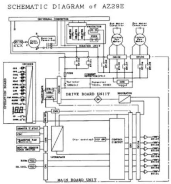
flowchart
graph TD
    A["Universal Connection"] --> B["Heater Unit"]
    B --> C["Driver Board Unit"]
    C --> D["Control Circuit"]
    D --> E["Main Board Unit"]
    F["Operator Board"] --> G["Drive Board Unit"]
    G --> H["Controller"]
    H --> I["Control Circuit"]
    I --> J["Drive Board Unit"]
    K["Controller"] --> L["Driver Board Unit"]
    M["Operator"] --> N["Driver Board Unit"]
    O["Controller"] --> P["Driver Board Unit"]
    Q["Operator"] --> R["Driver Board Unit"]
    S["Controller"] --> T["Driver Board Unit"]
    U["Operator"] --> V["Driver Board Unit"]
    W["Controller"] --> X["Driver Board Unit"]
    Y["Operator"] --> Z["Driver Board Unit"]
    AA["Controller"] --> AB["Driver Board Unit"]
    AC["Operator"] --> AD["Driver Board Unit"]
    AE["Controller"] --> AF["Driver Board Unit"]
    AG["Operator"] --> AH["Driver Board Unit"]
    AI["Controller"] --> AJ["Driver Board Unit"]
    AK["Operator"] --> AL["Driver Board Unit"]
    AM["Controller"] --> AN["Driver Board Unit"]
    AO["Operator"] --> AP["Driver Board Unit"]
    AQ["Controller"] --> AR["Driver Board Unit"]
    AS["Operator"] --> AT["Driver Board Unit"]
    AU["Controller"] --> AV["Driver Board Unit"]
    AW["Operator"] --> AX["Driver Board Unit"]
3900 Series, 208/230-Volt Wiring Diagrams
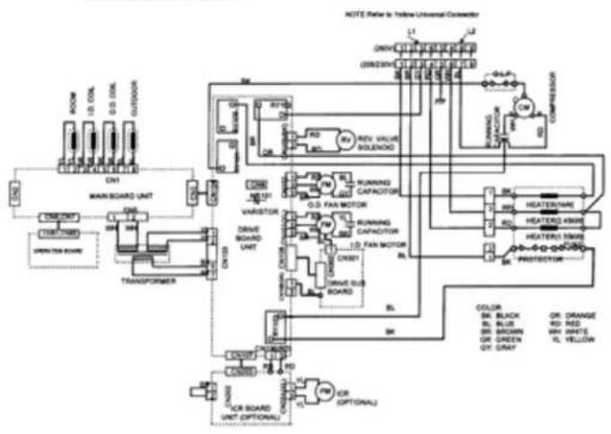
flowchart
graph TD
    A["MAIN BOARD UNIT"] --> B["CONTROLLER"]
    B --> C["DRIVE BOARD UNIT"]
    C --> D["DRIVE SUB BOARD"]
    D --> E["POWER"]
    E --> F["OR BOARD UNIT (OPTIONAL)"]
    F --> G["POWER"]
    G --> H["OR (OPTIONAL)"]
    H --> I["POWER"]
    I --> J["DRIVE SUB BOARD"]
    J --> K["DRIVE LOAD MOTOR"]
    K --> L["POWER"]
    L --> M["DRIVE LOAD MOTOR"]
    M --> N["POWER"]
    N --> O["DRIVE SUB BOARD"]
    O --> P["DRIVE LOAD MOTOR"]
    P --> Q["POWER"]
    Q --> R["DRIVE SUB BOARD"]
    R --> S["DRIVE LOAD MOTOR"]
    S --> T["POWER"]
    T --> U["DRIVE SUB BOARD"]
    U --> V["DRIVE LOAD MOTOR"]
    V --> W["POWER"]
    W --> X["DRIVE SUB BOARD"]
    X --> Y["DRIVE LOAD MOTOR"]
    Y --> Z["POWER"]
    Z --> AA["DRIVE SUB BOARD"]
3900 Series, 208/230-Volt Wiring Diagrams (continued)

flowchart
graph TD
    A["MAIN BOARD UNIT"] --> B["TRANSFORMER"]
    B --> C["CON1"]
    C --> D["ROOM"]
    C --> E["COIL"]
    C --> F["COIL"]
    C --> G["OUTDOOR"]
    B --> H["CON2"]
    H --> I["CON6 CN7"]
    I --> J["OPERATION BOARD"]
    B --> K["CON3"]
    K --> L["CON10"]
    L --> M["CON106(RD)"]
    M --> N["CN107"]
    N --> O["CN203"]
    O --> P["CR1"]
    P --> Q["ICR BOARD UNIT (OPTIONAL)"]
    Q --> R["CN202"]
    R --> S["CR1"]
    S --> T["ICR (OPTIONAL)"]

    subgraph Legend
        U["NOTE: Refer to Yellow Universal Connector"] --> V["L1"]
        V --> W["L2"]
        W --> X["L3"]
        X --> Y["L4"]
        Y --> Z["L5"]
        Z --> AA["L6"]
        AA --> AB["L7"]
        AB --> AC["L8"]
        AC --> AD["L9"]
        AD --> AE["L10"]
        AE --> AF["L11"]
        AF --> AG["L12"]
        AG --> AH["L13"]
        AH --> AI["L14"]
        AI --> AJ["L15"]
        AJ --> AK["L16"]
        AK --> AL["L17"]
        AL --> AM["L18"]
        AM --> AN["L19"]
        AN --> AO["L20"]
        AO --> AP["L21"]
        AP --> AQ["L22"]
        AQ --> AR["L23"]
        AR --> AS["L24"]
        AS --> AT["L25"]
        AT --> AU["L26"]
        AU --> AV["L27"]
        AV --> AW["L28"]
        AW --> AX["L29"]
        AX --> AY["L30"]
        AY --> AZ["L31"]
        AZ --> BA["L32"]
        BA --> BB["L33"]
        BB --> BC["L34"]
        BC --> BD["L35"]
        BD --> BE["L36"]
        BE --> BF["L37"]
        BF --> BG["L38"]
        BG --> BH["L39"]
        BH --> BI["L40"]
        BI --> BJ["L41"]
        BJ --> BK["L42"]
        BK --> BL["L43"]
        BL --> BM["L44"]
        BM --> BN["L45"]
        BN --> BO["L46"]
        BO --> BP["L47"]
        BP --> BQ["L48"]
        BQ --> BR["L49"]
        BR --> BS["L50"]
        BS --> BT["L51"]
        BT --> BU["L52"]
        BU --> BV["L53"]
        BV --> BW["L54"]
        BW --> BX["L55"]
        BX --> BY["L56"]
        BY --> BZ["L57"]
        BZ --> CA["L58"]
        CA --> CB["L59"]
        CB --> CC["L60"]
        CC --> CD["L61"]
        CD --> CE["L62"]
        CE --> CF["L63"]
        CF --> CG["L64"]
        CG --> CH["L65"]
        CH --> CI["L66"]
        CI --> CJ["L67"]
        CJ --> CK["L68"]
        CK --> CL["L69"]
        CL --> CM["COMPRESSOR"]
    end

    subgraph Legend
        DU["RUNNING CAPACITOR"] --> DV["RV REV. VALVE SOLENOID"] & DV_RD_GV
    end

    style Legend fill:#f9f,stroke:#333,stroke-width:2px
    note right of AB
        O: Black
        P: Black
        Q: Black
    end

    %% Color block
    %% Labels
    %% Colors/Bricks
    %% Note: Reference to Yellow Universal Connector
    %% Legend
    %% Labels
    %% Colors/Bricks
    %% Note
    %% Legend
    %% Color block
    %% Entity/Label
    %% Note: Reference to Yellow Universal Connector
    %% Note: Reference to Yellow Universal Connector
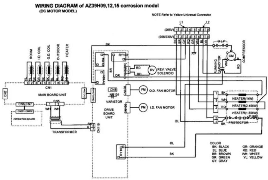
flowchart
graph TD
    A["MAIN BOARD UNIT"] --> B["TRANSFORMER"]
    B --> C["CON10"]
    C --> D["CON1"]
    D --> E["CON5"]
    E --> F["CON6"]
    F --> G["CON7"]
    G --> H["CON8"]
    H --> I["CON9"]
    I --> J["CON10"]

    subgraph MAIN BOARD UNIT
        K["CN1"] --> L["CN2"]
        M["CN5"] --> N["CN6"]
        O["CN7"] --> P["CN8"]
        Q["CN9"] --> R["CN10"]
        S["CN11"] --> T["CN12"]
    end

    subgraph TRANSFORMER
        U["CN10"] --> V["CN11"]
        W["CN11"] --> X["CN12"]
    end

    subgraph MAIN BOARD UNIT
        Y["CN1"] --> Z["CN2"]
        AA["CN5"] --> AB["CN6"]
        AC["CN7"] --> AD["CN8"]
        AE["CN9"] --> AF["CN10"]
        AG["CN11"] --> AH["CN12"]
    end

    subgraph TRANSFORMER
        AI["CN10"] --> AJ["CN11"]
        AK["CN11"] --> AL["CN12"]
    end

    subgraph MAIN BOARD UNIT
        AM["CN1"] --> AN["CN2"]
        AO["CN5"] --> AP["CN6"]
        AQ["CN7"] --> AR["CN8"]
        AS["CN9"] --> AT["CN10"]
        AU["CN11"] --> AV["CN12"]
    end

    subgraph TRANSFORMER
        AW["CN10"] --> AX["CN11"]
        AY["CN11"] --> AZ["CN12"]
    end

    subgraph MAIN BOARD UNIT
        BA["CN1"] --> BB["CN2"]
        BC["CN5"] --> BD["CN6"]
        BE["CN7"] --> BF["CN8"]
        BG["CN9"] --> BH["CN10"]
        BI["CN11"] --> BJ["CN12"]
    end

    subgraph TRANSFORMER
        BK["CN10"] --> BL["CN11"]
        BM["CN11"] --> BN["CN12"]
    end

    subgraph MAIN BOARD UNIT
        BO["CN1"] --> BP["CN2"]
        BQ["CN5"] --> BR["CN6"]
        BS["CN7"] --> BT["CN8"]
        BU["CN9"] --> BV["CN10"]
        BW["A"] --> BX["A"]
    end

    subgraph TRANSFORMER
        BY["BK"] --> BZ["BK"]
    end

    note right of A: NOTE: Refer to Yellow Universal Connector
    note right of B: REF: Refer to Yellow Universal Connector
    note right of AB: REF: Refer to Yellow Universal Connector
    note right of AC: REF: Refer to Yellow Universal Connector
    note right of AD: REF: Refer to Yellow Universal Connector
    note right of AE: REF: Refer to Yellow Universal Connector
    note right of BI: REF: Refer to Yellow Universal Connector
    note right of RW: REF: Refer to Yellow Universal Connector
    note right of GR: REF: Refer to Yellow Universal Connector
    note right of GY: REF: Refer to Yellow Universal Connector
    note right of BL: REF: Refer to Yellow Universal Connector
    note right of DR: REF: Refer to Yellow Universal Connector
    note right of RD: REF: Refer to Yellow Universal Connector
    note right of HEAT: REF: Refer to Yellow Universal Connector
    note right of HEATER: REF: Refer to Yellow Universal Connector
    note right of HEATER(1.55kW) : REF: Refer to Yellow Universal Connector
    note right of PROTECTOR : Ref: Refer to Yellow Universal Connector
    note right of BL : Ref: Refer to Yellow Universal Connector
    note right of BL : Ref: Refer to Yellow Universal Connector
    note right of BL : Ref: Refer to Yellow Universal Connector
    note right of BL : Ref: Refer to Yellow Universal Connector
    note right of BL : Ref: Refer to Yellow Universal Connector
    note right of BL : Ref: Refer to Yellow Universal Connector
    note right of BL : Ref: Refer to Yellow Universal Connector
    note right of BL : Rel : Ref: Refer to Yellow Universal Connector
    note right of BL : Red : Ref: Refer to Yellow Universal Connector
    note right of BL : White : Ref: Refer to Yellow Universal Connector
    note right of BL : Green : Ref: Refer to Yellow Universal Connector
    note right of BL : Gray : Ref: Refer to Yellow Universal Connector
3900 Series, 208/230-Volt Schematic Diagrams
Schematic Diagram of AZ39H AC motor model (07) Schematic Diagram of AZ39H AC motor model (09,12.15)
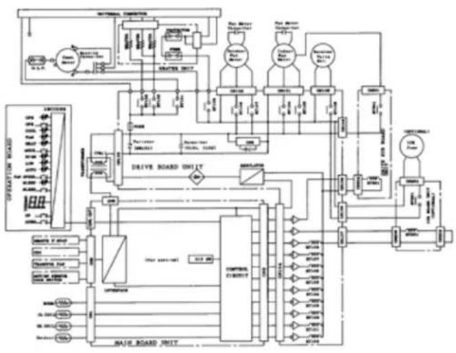
flowchart
graph TD
    A["Operating Motor"] --> B["Drive Board Unit"]
    B --> C["Control Unit"]
    C --> D["Motor 1"]
    C --> E["Motor 2"]
    C --> F["Motor 3"]
    C --> G["Motor 4"]
    C --> H["Motor 5"]
    C --> I["Motor 6"]
    C --> J["Motor 7"]
    C --> K["Motor 8"]
    C --> L["Motor 9"]
    C --> M["Motor 10"]
    C --> N["Motor 11"]
    C --> O["Motor 12"]
    C --> P["Motor 13"]
    C --> Q["Motor 14"]
    C --> R["Motor 15"]
    C --> S["Motor 16"]
    C --> T["Motor 17"]
    C --> U["Motor 18"]
    C --> V["Motor 19"]
    C --> W["Motor 20"]
    C --> X["Motor 21"]
    C --> Y["Motor 22"]
    C --> Z["Motor 23"]
    C --> AA["Motor 24"]
    C --> AB["Motor 25"]
    C --> AC["Motor 26"]
    C --> AD["Motor 27"]
    C --> AE["Motor 28"]
    C --> AF["Motor 29"]
    C --> AG["Motor 30"]
    C --> AH["Motor 31"]
    C --> AI["Motor 32"]
    C --> AJ["Motor 33"]
    C --> AK["Motor 34"]
    C --> AL["Motor 35"]
    C --> AM["Motor 36"]
    C --> AN["Motor 37"]
    C --> AO["Motor 38"]
    C --> AP["Motor 39"]
    C --> AQ["Motor 40"]
    C --> AR["Motor 41"]
    C --> AS["Motor 42"]
    C --> AT["Motor 43"]
    C --> AU["Motor 44"]
    C --> AV["Motor 45"]
    C --> AW["Motor 46"]
    C --> AX["Motor 47"]
    C --> AY["Motor 48"]
    C --> AZ["Motor 49"]
    C --> BA["Motor 50"]
    C --> BB["Motor 51"]
    C --> BC["Motor 52"]
    C --> BD["Motor 53"]
    C --> BE["Motor 54"]
    C --> BF["Motor 55"]
    C --> BG["Motor 56"]
    C --> BH["Motor 57"]
    C --> BI["Motor 58"]
    C --> BJ["Motor 59"]
    C --> BK["Motor 60"]
    C --> BL["Motor 61"]
    C --> BM["Motor 62"]
    C --> BN["Motor 63"]
    C --> BO["Motor 64"]
    C --> BP["Motor 65"]
    C --> BQ["Motor 66"]
    C --> BR["Motor 67"]
    C --> BS["Motor 68"]
    C --> BT["Motor 69"]
    C --> BU["Motor 70"]
    C --> BV["Motor 71"]
    C --> BW["Motor 72"]
    C --> BX["Motor 73"]
    C --> BY["Motor 74"]
    C --> BZ["Motor 75"]
    C --> CA["Motor 76"]
    C --> CB["Motor 77"]
    C --> CC["Motor 78"]
    C --> CD["Motor 79"]
    C --> CE["Motor 80"]
    C --> CF["Motor 81"]
    C --> CG["Motor 82"]
    C --> CH["Motor 83"]
    C --> CI["Motor 84"]
    C --> CJ["Motor 85"]
    C --> CK["Motor 86"]
    C --> CL["Motor 87"]
    C --> CM["Motor 88"]
    C --> CN["Motor 89"]
    C --> CO["Motor 90"]
    C --> CP["Motor 91"]
    C --> CS["Motor 92"]
    C --> CT["Motor 93"]
    C --> CU["Motor 94"]
    C --> CV["Motor 95"]
    C --> CW["Motor 96"]
    C --> CX["Motor 97"]
    C --> CY["Motor 98"]
    C --> CZ["Motor 99"]

flowchart
graph TD
    A["Driver Board Unit"] --> B["Main Board Unit"]
    B --> C["Drive Board Unit"]
    C --> D["Motor 1"]
    C --> E["Motor 2"]
    C --> F["Motor 3"]
    C --> G["Motor 4"]
    C --> H["Motor 5"]
    C --> I["Motor 6"]
    C --> J["Motor 7"]
    C --> K["Motor 8"]
    C --> L["Motor 9"]
    C --> M["Motor 10"]
    C --> N["Motor 11"]
    C --> O["Motor 12"]
    C --> P["Motor 13"]
    C --> Q["Motor 14"]
    C --> R["Motor 15"]
    C --> S["Motor 16"]
    C --> T["Motor 17"]
    C --> U["Motor 18"]
    C --> V["Motor 19"]
    C --> W["Motor 20"]
    C --> X["Motor 21"]
    C --> Y["Motor 22"]
    C --> Z["Motor 23"]
    C --> AA["Motor 24"]
    C --> AB["Motor 25"]
    C --> AC["Motor 26"]
    C --> AD["Motor 27"]
    C --> AE["Motor 28"]
    C --> AF["Motor 29"]
    C --> AG["Motor 30"]
    C --> AH["Motor 31"]
    C --> AI["Motor 32"]
    C --> AJ["Motor 33"]
    C --> AK["Motor 34"]
    C --> AL["Motor 35"]
    C --> AM["Motor 36"]
    C --> AN["Motor 37"]
    C --> AO["Motor 38"]
    C --> AP["Motor 39"]
    C --> AQ["Motor 40"]
    C --> AR["Motor 41"]
    C --> AS["Motor 42"]
    C --> AT["Motor 43"]
    C --> AU["Motor 44"]
    C --> AV["Motor 45"]
    C --> AW["Motor 46"]
    C --> AX["Motor 47"]
    C --> AY["Motor 48"]
    C --> AZ["Motor 49"]
    C --> BA["Motor 50"]
    C --> BB["Motor 51"]
    C --> BC["Motor 52"]
    C --> BD["Motor 53"]
    C --> BE["Motor 54"]
    C --> BF["Motor 55"]
    C --> BG["Motor 56"]
    C --> BH["Motor 57"]
    C --> BI["Motor 58"]
    C --> BJ["Motor 59"]
    C --> BK["Motor 60"]
    C --> BL["Motor 61"]
    C --> BM["Motor 62"]
    C --> BN["Motor 63"]
    C --> BO["Motor 64"]
    C --> BP["Motor 65"]
    C --> BQ["Motor 66"]
    C --> BR["Motor 67"]
    C --> BS["Motor 68"]
    C --> BT["Motor 69"]
    C --> BU["Motor 70"]
    C --> BV["Motor 71"]
    C --> BW["Motor 72"]
    C --> BX["Motor 73"]
    C --> BY["Motor 74"]
    C --> BZ["Motor 75"]
    C --> CA["Motor 76"]
    C --> CB["Motor 77"]
    C --> CC["Motor 78"]
    C --> CD["Motor 79"]
    C --> CE["Motor 80"]
Schematic diagram of AZ39H DC motor model

flowchart
graph TD
    A["MAIN BOARD UNIT"] --> B["DRIVE BOARD UNIT"]
    B --> C["DRIVE POWER"]
    C --> D["POWER"]
    D --> E["POWER"]
    E --> F["POWER"]
    F --> G["POWER"]
    G --> H["POWER"]
    H --> I["POWER"]
    I --> J["POWER"]
    J --> K["POWER"]
    K --> L["POWER"]
    L --> M["POWER"]
    M --> N["POWER"]
    N --> O["POWER"]
    O --> P["POWER"]
    P --> Q["POWER"]
    Q --> R["POWER"]
    R --> S["POWER"]
    S --> T["POWER"]
    T --> U["POWER"]
    U --> V["POWER"]
    V --> W["POWER"]
    W --> X["POWER"]
    X --> Y["POWER"]
    Y --> Z["POWER"]
    Z --> AA["POWER"]
    AA --> AB["POWER"]
    AB --> AC["POWER"]
    AC --> AD["POWER"]
    AD --> AE["POWER"]
    AE --> AF["POWER"]
    AF --> AG["POWER"]
    AG --> AH["POWER"]
    AH --> AI["POWER"]
    AI --> AJ["POWER"]
    AJ --> AK["POWER"]
    AK --> AL["POWER"]
    AL --> AM["POWER"]
    AM --> AN["POWER"]
    AN --> AO["POWER"]
    AO --> AP["POWER"]
    AP --> AQ["POWER"]
    AQ --> AR["POWER"]
    AR --> AS["POWER"]
    AS --> AT["POWER"]
    AT --> AU["POWER"]
    AU --> AV["POWER"]
    AV --> AW["POWER"]
    AW --> AX["POWER"]
    AX --> AY["POWER"]
Typical 5800 Series Wiring Diagram
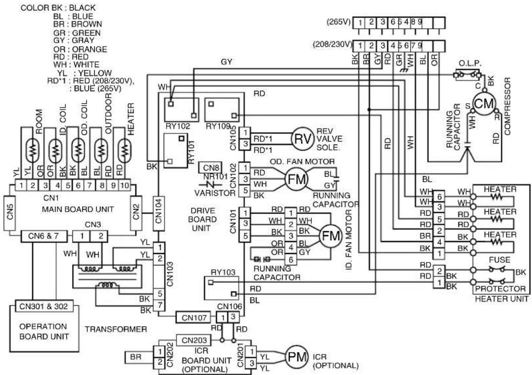
flowchart
graph TD
    subgraph MAIN_BOARD_UNIT
        CN1["CN1 MAIN BOARD UNIT"] --> CN2["CN2"]
        CN1 --> CN3["CN3"]
        CN1 --> CN4["CN4"]
        CN1 --> CN5["CN5"]
        CN1 --> CN6["CN6 & 7"]
        CN1 --> CN7["CN7 & 7"]
        CN1 --> CN8["CN8 NR101 VARISTOR"]
        CN1 --> CN9["CN9"]
        CN1 --> CN10["CN10"]
        CN1 --> CN11["CN10"]
        CN1 --> CN12["CN10"]
        CN1 --> CN13["CN103"]
        CN1 --> CN14["CN104"]
        CN1 --> CN15["CN105"]
        CN1 --> CN16["CN106"]
        CN1 --> CN17["CN107"]
        CN1 --> CN203["CN203"]
        CN203 --> TRANSFORMER
    end

    subgraph OUTPUT_UNIT
        CN203 --> TRANSFORMER
        TRANSFORMER --> BR["BR"]
        TRANSFORMER --> CN202["CN202"]
        TRANSFORMER --> CN203["CN203"]
        TRANSFORMER --> CN204["CN204"]
        TRANSFORMER --> CN205["CN205"]
        TRANSFORMER --> CN206["CN206"]
        TRANSFORMER --> CN207["CN207"]
        TRANSFORMER --> CN208["CN208"]
        TRANSFORMER --> CN209["CN209"]
        TRANSFORMER --> CN210["CN210"]
        TRANSFORMER --> CN211["CN211"]
        TRANSFORMER --> CN212["CN212"]
        TRANSFORMER --> CN213["CN213"]
        TRANSFORMER --> CN214["CN214"]
        TRANSFORMER --> CN215["CN215"]
        TRANSFORMER --> CN216["CN216"]
        TRANSFORMER --> CN217["CN217"]
        TRANSFORMER --> CN218["CN218"]
        TRANSFORMER --> CN219["CN219"]
        TRANSFORMER --> CN220["CN220"]
        TRANSFORMER --> CN221["CN221"]
        TRANSFORMER --> CN222["CN222"]
        TRANSFORMER --> CN223["CN223"]
        TRANSFORMER --> CN224["CN224"]
        TRANSFORMER --> CN225["CN225"]
        TRANSFORMER --> CN226["CN226"]
        TRANSFORMER --> CN227["CN227"]
        TRANSFORMER --> CN228["CN228"]
        TRANSFORMER --> CN229["CN229"]
        TRANSFORMER --> CN230["CN230"]
    end

    subgraph OUTPUT_UNIT
        RN["RV REV VALVE SOLE."] --> RV
        RV --> RV_OUT
        RV_OUT --> RV_OUT
        RV_OUT --> RV_OUT
        RV_OUT --> RV_OUT
    end

    subgraph OUTPUT_UNIT
        ID["ID. FAN MOTOR FM"] --> ID_OUT
        ID_OUT --> ID_OUT
    end

    subgraph OUTPUT_UNIT
        ID_RD["WH"] --> ID_OUT
        ID_RD_OUT --> ID_OUT
    end

    subgraph OUTPUT_UNIT
        ID_BK["WH"] --> ID_OUT
        ID_BK_OUT --> ID_OUT
    end

    subgraph OUTPUT_UNIT
        ID_BK_BK["WH"] --> ID_OUT
        ID_BK_BK_OUT --> ID_OUT
    end

    subgraph OUTPUT_UNIT
        ID_BK_BK_BK["WH"] --> ID_OUT
        ID_BK_BK_BK_OUT --> ID_OUT
    end

    subgraph OUTPUT_UNIT
        ID_BK_BK_BK["WH"] --> ID_OUT
        ID_BK_BK_BK_OUT --> ID_OUT
    end

    subgraph OUTPUT_UNIT
        ID_BK_BK_BK["WH"] --> ID_OUT
        ID_BK_BK_BK_OUT --> ID_OUT
    end

    subgraph OUTPUT_UNIT
        ID_BK_BK_BB["WH"] --> ID_OUT
        ID_BK_BK_BB_OUT
    end

    subgraph OUTPUT_UNIT
        ID_BK_BK_BW["WH"] --> ID_OUT
        ID_BK_BK_BW_OUT
    end

    subgraph OUTPUT_UNIT
        ID_BK_BK_BW["WH"] --> ID_OUT
        ID_BK_BK_BW_OUT
    end

    subgraph OUTPUT_UNIT
        ID_BK_BK_BW_BW["WH"] --> ID_OUT
        ID_BK_BK_BW_OUT
    end

    subgraph OUTPUT_UNIT
        ID_BK_BK_BW_BW["WH"] --> ID_OUT
        ID_BK_BK_BW_OUT
    end

    subgraph OUTPUT_UNIT
        ID_BK_BK_BW_BW["WH"] --> ID_OUT
        ID_BK_BK_BW_OUT
    end

    subgraph OUTPUT_UNIT:
        ID_BK_BK_BW_BW["WH"] --> ID_OUT
        ID_BK_BK_BW_OUT
    end

    subgraph OUTPUT_UNIT:
        ID_BK_BK_BW_BW["WH"] --> ID_OUT
        ID_BK_BK_BW_OUT
    end

    subgraph OUTPUT_UNIT:
        ID_BK_BK_BW_BW["WH"] --> ID_OUT
        ID_BK_BK_BW_OUT
</details>
Typical 5800 Series Schematic Diagram

<details>
<summary>flowchart</summary>
```mermaid
graph TD
subgraph OPERATIONS
A["OPERATION BOARD"] --> B["TRI1"]
A --> C["TRANSFORMER"]
A --> D["DRIVE BOARD UNIT"]
A --> E["ICR BOARD UNIT"]
end
subgraph MAIN_BOARD_UNIT
F["MAIN BOARD UNIT"] --> G["CONTROL CIRCUIT"]
G --> H["CN2"]
G --> I["CN104"]
G --> J["CN107"]
G --> K["CN203"]
G --> L["CN202"]
subgraph UNIVERSAL_CONNECTOR
M["UNIVERSAL CONNECTOR"] --> N["FUSE"]
N --> O["PROTECTOR"]
O --> P["HEATER UNIT"]
P --> Q["FAN MOTOR CAPACITOR"]
Q --> R["OUTDOOR FAN MOTOR"]
R --> S["CN102"]
S --> T["FUSSE (FU101)"]
T --> U["VARISTOR (NR101)"]
U --> V["Casacitor (C101, C102)"]
V --> W["CN8"]
W --> X["REGULATOR"]
end
subgraph ICR_BOARD_UNIT
Y["ICR BOARD UNIT (OPTIONAL)"] --> Z["RY201"]
AA["ICR BOARD UNIT (OPTIONAL)"] --> AB["RY201"]
AC["ICR BOARD UNIT (OPTIONAL)"] --> AD["RY201"]
end
subgraph OUTPUT pressures
AE["OPE"] --> AF["COOL"]
AF --> AG["FAT"]
AG --> AH["MODE"]
AH --> AI["HIGH"]
AI --> AJ["LCAV"]
AJ --> AK["AUTO"]
AK --> AL["RN SPEED"]
AL --> AM["UP DOWN"]
AN["OPF"] --> AO["DECODER"]
AP["OPS"] --> AQ["TRANSMOTER"]
AR["OPEN"] --> AS["CONTENTS"]
AT["RESPECTRATOR"] --> AU["FUSE"]
AV["FUSSE"] --> AW["FUSE (FU101)"]
AX["FUSSE"] --> AY["FUSSE (FU101)"]
AZ["FUSSE"] --> BA["FUSSE (FU101)"]
BB["FUSSE"] --> BC["FUSSE (FU101)"]
BD["FUSSE"] --> BE["FUSSE (FU101)"]
end
subgraph OUTPUT CURRENTVolume
BF["INDOOR FAN MOTOR"] --> BG["FUSSE (FU101)"]
BH["FUSSE"] --> BI["FUSSE (FU101)"]
BJ["FUSSE"] --> BK["FUSSE (FU101)"]
BL["FUSSE"] --> BM["FUSSE (FU101)"]
BN["FUSSE"] --> BO["FUSSE (FU101)"]
end
subgraph ICRBoardUnit
BP["ICR BOARD UNIT (OPTIONAL)"] --> BQ["RY201"]
end
subgraph OUTPUT PRESSURE
BR["INTERNATIONAL PRESSURE"] --> BS["FUSSE (FU101)"]
BT["FUSSE"] --> BU["FUSSE (FU101)"]
BV["FUSSE"] --> BW["FUSSE (FU101)"]
BX["FUSSE"] --> BY["FUSSE (FU101)"]
end
subgraph OUTPUT CURRENTVolume
BQ --> CA["FUSSE (FU101)"]
CB["FUSSE"] --> CC["FUSSE (FU101)"]
DD["FUSSE"] --> DE["FUSSE (FU101)"]
end
subgraph OUTPUT PRESSURE
BE --> CF["FUSSE (FU101)"]
GD["FUSSE"] --> DH["FUSSE (FU101)"]
DI["FUSSE"] --> DJ["FUSSE (FU101)"]
end
subgraph OUTPUT CURRENTVolume
BEQ["FUSSE (FU101)"]
BQG["FUSSE"] --> BHG["FUSSE (FU101)"]
BIQ["FUSSE"] --> BJQ["FUSSE (FU101)"]
BKQ["FUSSE"] --> BLQ["FUSSE (FU101)"]
end
subgraph OUTPUT PRESSURE
BQH["FUSSE (FU101)"]
BQI["FUSSE"] --> BJI["FUSSE (FU101)"]
BKII["FUSSE"] --> BLII["FUSSE (FU101)"]
end
subgraph OUTPUT CURRENTVolume
BQJ["FUSSE (FU101)"]
BQK["FUSSE"] --> BLK["FUSSE (FU101)"]
BNJ["GND"] --> BOJ["GND"]
end
subgraph OUTPUT PRESSURE
BQL["FUSSE (FU101)"]
BQM["GND"] --> BNJ
end
Suggested Bid Form Specifications
The following are suggested specifications for the Zoneline® 2900 Series Packaged Terminal Air Conditioner, the 3900 Series Packaged Terminal Heat Pump and the 5800 Series Packaged Terminal Heat Pump.
The contractor will furnish Packaged Terminal Air Conditioners of the sizes and capacities shown on the schedule and in the specifications. The units shall be located as shown on the drawings and each shall consist of a chassis, room cabinet, wall case, sub-base if specified, and outdoor grille.
Units shall be listed by UL, and ARI and cUL certified as to capacity and efficiency and shall be GE Zoneline models or equal. Unit dimensions shall not exceed 42-1/8" wide and 16-1/4" high with room cabinet in place.
Units shall be designed to operate on (208) (230) (265) volts, 60 Hz., single-phase power.
Chassis. The air conditioner chassis shall be the standard product of the manufacturer and shall be shipped in protective cartons to prevent damage. Cartons shall be appropriately marked at the factory with wording sufficient to warn handlers against improper stacking, up-ending, rolling or dropping.
The chassis shall be the slide-in type, ready to operate after installation.
Each shall consist of the following sections and components:
- Each unit shall have a matching, easily removable, textured finish, wrap-around room cabinet molded of high-temperature styrene to resist corrosion and damage. The room cabinet shall have slide-out washable filters accessible without requiring removal of room cabinet from chassis;
- Hermetically sealed refrigerant system with external vibration isolated rotary-type compressor, condenser and evaporator coils and capillary refrigerant control. Airflow system consisting of one permanently lubricated two-speed fan motor for the outdoor fan and a separate permanently lubricated two-speed fan motor for the indoor fan. Outdoor fan shall be multi-blade axial-flow design made of non-corrosive material. Indoor fan shall be of a design to optimize airflow and operating sound. All motors on the exterior side of the weather barrier shall be of an enclosed design to reduce the effects of moisture and corrosion;
- Line-cord connected units shall require a line-cord power connection kit with integral Leakage Current Detection and Interruption device or Arc Fault Current Interrupter as required by National Electrical Code(NEC) and Underwriters Laboratories. The unit shall have a universal resistance heater with output determined by connection to the power source with the appropriate power connection kit to provide specified heat output;
- A fan-cycle switch to permit continuous fan operation or fan cycle operation, independently selectable for heating and cooling operation;
- Fan-only operation in either high or low fan speed selectable by room occupant;
-
A positive cooling condensate disposal system which meets the test requirements of applicable A.R.I. Standard 310-04 (for Packaged Terminal Air Conditioners) and 380-04 (for Packaged Terminal Heat Pumps) (80°F dry bulb, 75°F wet bulb, 80% relative humidity);
-
Condenser and evaporator coils to be constructed of copper tubing and aluminum plate fins designed to achieve EER and COP rating of the unit;
- Indoor and outdoor airflows that match the capacity of the coils for efficient heat transfer. Water blow-off shall not occur on the indoor coil;
- Adjustable indoor discharge air louvers that provide a 50° off vertical air pattern with an alternate position to provide a 40° off vertical air pattern;
- Easily accessible controls for selection of unit operation and thermostat setting. Controls shall be covered by a hinged door;
• Air discharge area accessible for cleaning without tools when room front is removed for 2900 and 3900 Series; - Positive-closing, manually controlled, three-position fresh-air vent capable of providing selection of fully open, partially open or closed setting. Vent door is to be secured for shipping;
- Solid-state thermostat control to sense room temperature;
- Electronic temperature limiting with seven independent heating and cooling settings to limit maximum and minimum temperatures without restricting movement of thermostat control knob;
- Freeze Sentinel to automatically activate the electric resistance heater and fan motor to warm and circulate indoor air to help prevent damage due to freezing temperatures. Freeze Sentinel shall operate as long as unit is connected to powered electrical circuit and unit shall provide ability for owner to defeat the Freeze Sentinel operation;
- Heat Sentinel to automatically activate air conditioner operation when the unit is in the STOP setting when the room temperature warms to 85°F and turns air conditioner operation off when the room temperature cools to 80°F, if selected by owner;
- Compatible with two-wire Central Desk Control systems;
- Remote Thermostat compatibility with Class 2 remote thermostat;
- Connections to interface with a transfer fan to move air into another room;
- Connections to interface with occupancy sensors; Unit shall have means of electrical connection listed by Underwriters Laboratories and compatible with the unit's required voltage and ampacity in conformance with National Electrical Code and local codes.
Additional specifications for GE Zoneline 3900 or 5800 Series Packaged Terminal Heat Pumps
Heat pump units shall provide operation that will either: A) automatically phase in partial electric resistance heat, if outdoor temperature is below 46^ F, simultaneously with heat pump if heat pump alone is unable to maintain room temperature; or B) use partial electric resistance heat simultaneous with heat pump operation any time the outdoor temperature is below 45^ F. Selection of A or B operation is made by means of a selector switch concealed from room occupant. In either A or B operation, the unit will switch to full resistance heat if room temperature continues to decline or the outdoor temperature falls below 25^ F. If the outdoor temperature is above 46^ F, unit will lock out electric resistance heat and operate on heat pump only.
Suggested Bid Form Specifications (continued)
Heat pump unit shall include Reverse Cycle Defrost that automatically begins a defrost cycle when microprocessor determines criteria for defrosting has been met. Defrosting shall be accomplished by systematically ceasing heat pump operation, pausing to allow internal refrigerant pressures to equalize, then operating the compressor with the flow of refrigerant reversed to allow the hot gas to flow through the outdoor coil, melting the accumulated frost. The unit shall automatically resume heat pump operation, after pausing to allow refrigerant pressures to equalize, at conclusion of defrost cycle.
The unit shall be equipped with a temperature-activated drain valve to allow water generated in heat pump operation and defrost cycles to drain into the wall case rather than being deposited on the outdoor coil.
In the event of compressor failure during heat pump operation, the unit shall automatically switch to electric resistance heat to maintain selected room temperature regardless of outdoor temperatures.
The unit shall have a switch concealed from room occupant to allow heat pump operation to be overridden and heat provided by electric resistance heat regardless of outdoor temperature.
In the event of compressor failure during heat pump operation, unit shall automatically switch to electric resistance heat to maintain selected room temperature regardless of outdoor temperatures.
Specifications for optional Internal Condensate Removal (ICR) system for 3900 or 5800 Series heat pump units.
The unit shall have a factory-installed Internal Condensate Removal (ICR) system to permit unit to automatically dispose of heat-pump-generated condensate water with no overflow to outdoors during heating under outdoor ambient of 55^ f dry bulb, 90% relative humidity; indoor ambient 70^ f dry bulb, 52% relative humidity, for four hours of continuous run time.
Wall Cases and Grilles (needed for new installations.) (Alternate specification for steel wall case)
Wall Case. The wall case shall be constructed of heavy-gauge, insulated, zinc-coated phosphated steel with a protective baked-on enamel finish. Bottom critical points of the steel wall case shall be coated with petroleum microcrystalline wax for added corrosion protection and shall meet ASTM B-117, 1800-hour hot air aerated salt spray test.
(Alternate specification for molded wall case)
Wall Case. The wall case shall be constructed of a non-corroding fiberglass-reinforced polyester compound.
Cases shall be installed through exterior walls where shown on the plans and shall be installed per manufacturer's installation instructions. In no instance shall fasteners be used through the bottom in order to retain the water integrity of the bottom of the wall case.
Outside weather panels shipped with the cases shall remain in place until the outdoor air louvers and chassis are installed, at which time they are to be removed and discarded by the installer.
Outside Grille. Each unit shall be equipped with a standard exterior grille that has been designed to allow unit operation in high ambient conditions. Grilles shall be of material and design specified.
Special grilles or customer louver sections to be supplied by others will conform to a minimum of 65% free area (as calculated by ASHRAE) to allow for proper unit operation and shall be submitted to the PTAC/PTHP manufacturer, if requested, for feasibility and airflow characteristics.
Specifications for Sub-Base (if required)
Sub-Base. Each unit shall have a field-installed UL-listed electrical sub-base. The sub-base shall be attached to the lower inside flange of the wall case prior to installation in the exterior wall. It shall include adjustable screws at the bottom corners to permit exact leveling of the wall case. The sub-base shall have a factory-installed receptacle to allow unit line cord to plug into mating receptacle and shall have a chaseway to contain and conceal the line cord. The sub-base shall have side panels adjustable from a minimum of 2-3/8" to a maximum of 13-3/4" to enclose the area under the wall case.
Weather Resistance. Complete unit including outside louver shall be submitted to an independent agency for weather-resistance tests.
Air-infiltration test to be conducted in accordance with ASTM E283-91. With static air pressure differential of 1.57 lb./ft. ^2 (.3" H ^2 O) equivalent to 25 mph wind, allowable air infiltration shall not exceed 7 ft. ^3 /min.
Water-infiltration test to be conducted in accordance with ASTM E331-86 with static air pressure differential of 10.0 lb./ft ^2 (1.93" H ^2 O) equivalent to 63 mph wind, 5.0 gal./ft ^2 (8" rain/ft ^2 /hr.) for 15 minutes and there shall be no leakage into the room.
Approvals. Units shall be certified under the ARI and cUL certification program and listed by UL.
Service. Submit complete information with bid covering service availability to whom service on units will be assigned, along with complete address and phone number, including phone number of emergency service personnel.
Start-Up, Adjust, Demonstrate. Contractor shall be responsible for the initial starting of units, adjustments thereto, etc., to place the units in required operating condition. Contractor shall demonstrate to the owner or his representative the operation of units for both summer and winter functions.
Warranty. The warranty shall be a full one-year parts and labor on the entire unit, plus an additional full four years parts and labor for the sealed refrigerating system, including service call for diagnosis and transportation to and from service shop (if necessary) at no charge to the customer. The warranty shall also include a limited second-through-fifth-year parts-only warranty for fan motors, switches, thermostat, heater, heater protectors, compressor overload, solenoids, circuit boards, auxiliary controls, thermistors, frost controls, ICR pump, capacitors, varistors and indoor blower bearing.
Installation Responsibility. Units shall be installed according to the manufacturer's recommendations and the manufacturer shall not be responsible for unit failure as a result of improper installation, or unit performance when installed with accessories not approved by the manufacturer.
Zoneline® Chassis Nomenclature
The Zoneline chassis is identified by a model number defining the type of unit, cooling capacity, electrical information and optional features included on the unit. When specifying or ordering the Zoneline chassis use of this nomenclature will assure receiving the correct unit.
EXAMPLE
| A | Z | 5 | 8 | H | 1 | 2 | D | A | D |
| Zoneline packaged terminal chassis | Chassis series29=deluxe line cool/electric heat39=deluxe line heat pump58=premium line heat pump | Nominal cooling capacity07=7,000 BTUH cooling09=9,000 BTUH cooling12=12,000 BTUH cooling15=15,000 BTUH cooling | Universal power connection | ||||||
| Unit typeE=cooling with electric resistance heatH=heat pump with electric resistance heat | Voltage/Phase/FrequencyD=230/208 Volt, single phase, 60 HzE=265 Volt, single phase, 60 Hz | Special FeaturesB=base unitC=corrosion treatedD=internal condensate removal (IICR) system (heat pump models only) (not for coastal areas)P=Dry Air 25 | |||||||
Receptacles/Sub-Bases

Tandem
230/208V 15 Amp NEMA6-15R

Perpendicular
230/208V 20 Amp NEMA6-20R

Large tandem
230/208V 30 Amp NEMA6-30R

265V 15 Amp
NEMA7-15R

265V 20 Amp
NEMA7-20R
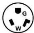
265V 30 Amp
NEMA7-30R
Sub-Bases
RAK204U RAK204D15P RAK204D20P RAK204D30P RAK204E15 RAK204E20 RAK204E30
| Voltage N/A 230/208 230/208 230/208 265 265 265 | |||||||
| Amps | N/A | 15 | 20 | 30 | 15 | 20 | 30 |
| Receptacle | N/A | NEMA6-20R | NEMA6-20R | NEMA6-30R | NEMA7-15R | NEMA7-20R | NEMA7-30R |
230/208-Volt sub-bases include appropriate power cord kit.
265-Volt units are to be direct connected. Cordset through enclosed choseway into interior sub-base receptacle meets the NEC requirements.
Power connection kits are required on all Zoneline chassis (see chart below).
The correct kit for the installation is determined by the voltage and amperage of the electrical circuit and the means of connecting the unit to the building wiring. If the unit is to be plugged into a receptacle, a line cord kit would be used; if the unit is to be permanently connected, a permanent connection kit would be used. 265-volt cord set units must be installed in compliance with National Electrical Code.
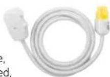
151
RAK3153/RAK3203/RAK3303
230/208-volt line cord
connection kit
Power connection kits
required on all models. See specification sheet for heater KW and branch circuit ampacity.

RAK4157/RAK4207/RAK4307 230/208-volt universal power supply kit

RAK5157/RAK5207/RAK5307
265-volt universal power
supply kit
| 230/208-volt | Line-cord connected units | ||
| LCDI Power Connection Kit | RAK3153 | RAK3203 | RAK3303 |
| Heeler KW | 2.55/2.09 | 3.45/2.82 | 5.00/4.09 |
| Watts | 2,550/2,090 | 3,450/2,820 | 5,000/4,090 |
| BTUH | 8,600/7,100 | 11,700/9,600 | 17,000/13,900 |
| Amps | 11.6/10.6 | 15.6/14.2 | 22.4/20.4 |
| Min. circuit amps | 15 | 20 | 30 |
| Recommended protective device | 15-amp time-delay time-delay fuse or breaker | 20-amp time-delay fuse or breaker | 30-amp fuse or breaker |
*To be used with sub-base
| 265-volt Permanently connected units* (Cord set) | ||
| RAK5172 | RAK5202 | RAK5302 |
| 2.55 | 3.45 | 5.0 |
| 2,560 | 3,450 | 5,000 |
| 8,600 | 11,700 | 17,000 |
| 10.3 | 13.8 | 19.6 |
| 15 20 | 30 | |
| 15-amptime-delay fuse | 20-amptime-delay fuse | 30-amptime-delay fuse |
| 230/208-volt | Direct-Connection Kit** | ||
| RAK4157 | RAK4207 | RAK4307 | |
| Heater KW | 2.55/2.09 | 3.45/2.82 | 5.00/6.09 |
| Watts | 2,550/2,090 | 3.450/2,820 | 5,000/4,030 |
| BTUH | 8,600/7,100 | 11.700/9,600 | 17,000/13,900 |
| Amos | 11.6/10.6 | 15.6/14.2 | 22.4/20.4 |
| Min. circuit amps | 15 | 20 | 30 |
| Recommended protective device | 15-amp time-delay fuse or breaker | 20-amp time-delay time-delay fuse or breaker | 30-amp fuse or breaker |
**To be used with sub-base or connection to building wiring
| 265-volt Direct-Connection Kit** | ||
| RAK5157 | RAK5207 | RAK5307 |
| 2.55 | 3.45 | 5.0 |
| 2,560 | 3,450 | 5,000 |
| 8,600 | 11,700 | 17,000 |
| 10.3 | 13.8 | 19.6 |
| 15 20 | 30 | |
| 15-omp time-delay fuse | 20-omp time-delay fuse | 30-amp time-delay fuse |
Preliminary Specifications
| Deluxe series - cooling & electric heat | Dry Air 25 | ||||||
| 2900 series units | Dry Air 25 | ||||||
| 230/208V Models | AZ29E07D | AZ29E09D | AZ29E12D | AZ29E15D | AZ29E07DAP | AZ29E09DAP | AZ29E12DAP |
| Capacity | |||||||
| Cooling BTUH | 7,100/6,900 | 9,300/8,900 | 11,700/11,500 | 14,600/14,300 | 6,800/6,600 | 8,800/8,500 | 11,200/11,000 |
| EER (BTU/Watt) | 12.7/12.7 | 12.0/12.0 | 11.5/11.5 | 10.2/10.2 | 12.1/12.1 | 11.5/11.5 | 11.0/11.0 |
| Dehumidification Pts/Hr | 1.7 | 2.7 | 3.6 | 4.6 | 2.3 | 3.4 | 4.5 |
| Sensible heat ratio @ 230 volts | 75% | 68% | 67% | 67% | 66% | 58% | 57% |
| CFM, indoor fan high | 250 | 270 | 290 | 310 | 210 | 230 | 240 |
| CFM, indoor fan low | 215 | 235 | 240 | 280 | 175 | 200 | 210 |
| Vent CFM (full open/partial open) | 50/40 | 70/45 | 75/45 | 75/45 | 50/40 | 70/45 | 75/45 |
| Power/Ratings | |||||||
| Power factor | 86/87 | 86/87 | 91/91 | 89/90 | 87/87 | 86/86 | 91/91 |
| Watts | 560/545 | 775/745 | 1,020/1,000 | 1,430/1,405 | 560/545 | 765/740 | 1,020/1,000 |
| Amperes, F.L. | 2.8/3.0 | 3.8/4.1 | 4.9/5.3 | 7.0/7.5 | 2.8/3.0 | 3.8/4.1 | 4.9/5.3 |
| Amperes, L.R. | 19.0 | 21.0 | 31.0 | 38.0 | 19.0 | 21.0 | 31.0 |
| Weight (Net/Ship) | 100/115 | 101/116 | 105/120 | 115/130 | 100/115 | 101/116 | 105/120 |
| Sound Transmission Class (STC) | 29 | 29 | 29 | 29 | 29 | 29 | 29 |
| 265V Models AZ29E07E AZ29E09E AZ29E12E AZ29E15E AZ29E07E AP AZ29E09E AP AZ29E12EAP | |||||||
| Capacity | |||||||
| Cooling BTUH | 7,100 | 9,000 | 11,700 | 14,600 | 6,800 | 8,600 | 11,200 |
| EER (BTU/Watt) | 12.7 | 12.0 | 11.5 | 10.2 | 12.1 | 11.5 | 11.0 |
| Dehumidification Pts/Hr | 1.7 | 2.7 | 3.6 | 4.6 | 2.3 | 3.4 | 4.4 |
| Sensible heat ratio @ 265 volts | 75% | 68% | 67% | 67% | 66% | 58% | 57% |
| CFM, indoor fan high | 250 | 270 | 290 | 310 | 210 | 235 | 240 |
| CFM, indoor fan low | 215 | 235 | 240 | 280 | 175 | 200 | 210 |
| Vent CFM (full open/partial open) | 50/40 | 70/45 | 75/45 | 75/45 | 50/40 | 70/45 | 75/45 |
| power/Ratings | |||||||
| Power factor | 87 | 86 | 87 | 90 | 88 | 86 | 87 |
| Watts | 560 | 750 | 1,020 | 1,435 | 560 | 750 | 1,020 |
| Amperes, F.L. | 2.4 | 3.3 | 4.4 | 6.0 | 2.4 | 3.3 | 4.4 |
| Amperes, L.R. | 16.0 | 18.0 | 24.0 | 31.0 | 16.0 | 18.0 | 24.0 |
| Weight (Net/Ship) | 100/115 | 100/115 | 105/120 | 115/130 | 100/115 | 101/116 | 105/120 |
| Sound Transmission Class (STC) | 29 | 29 | 29 | 29 | 29 | 29 | 29 |
| Deluxe series - heat pump units** Premium series - heat pump units | ||||||||
| 3900 series units | 5800 series units | |||||||
| 230/208V Models | AZ39H07D | AZ39H09D | AZ39H12D | AZ39H15D | AZ58H07D | AZ58H09D | AZ58H12D | AZ58H15D |
| Capacity | ||||||||
| Cooling BTUH | 7,100/6,900 | 9,400/9,150 | 11,850/11,500 | 14,750/14,350 | 7,300/7,000 | 9,300/9,050 | 11,800/11,600 | 14,700/14,400 |
| EER (BTU/Wattl) | 12.7/12.7 | 12.0/12.0 | 11.5/11.5 | 10.0/10.0 | 13.0/13.0 | 12.0/12.0 | 11.7/11.7 | 10.3/10.3 |
| Dehumidification Pts/Hr | 1.7 | 2.7 | 3.6 | 4.5 | 2.1 | 3.0 | 4.0 | 4.8 |
| Sensible heat ratio @ 230 volts | 75% | 68% | 67% | 67% | 75% | 67% | 68% | 65% |
| CFM, indoor fan high | 250 | 270 | 300 | 310 | 250 | 265 | 350 | 365 |
| CFM, indoor fan low | 215 | 235 | 260 | 260 | 230 | 245 | 330 | 345 |
| Vent CFM (full open/partial open) | 50/40 | 70/45 | 75/45 | 75/45 | 40/35 | 65/60 | 70/65 | 70/65 |
| Power/Ratings | ||||||||
| Power factor | 87 | 88 | 91 | 92 | 95 | 96 | 94 | 95 |
| Watts | 560/545 | 785/760 | 1,030/1,000 | 1,480/1,440 | 560/540 | 760/735 | 1,010/990 | 1,425/1,400 |
| Amperes, F.L. | 2.9/3.0 | 3.8/4.1 | 4.9/5.3 | 7.0/7.5 | 2.7/2.8 | 3.6/3.8 | 4.6/5.0 | 6.5/7.0 |
| Amperes, L.R. | 190 | 210 | 310 | 380 | 19.0 | 21.0 | 33.0 | 38.0 |
| Reverse cycle heat BTUH | 6,400/6,200 | 8,500/8,250 | 10,900/10,700 | 13,750/13,400 | 6,400/6,200 | 8,400/8,200 | 10,900/10,700 | 13,800/13,800 |
| COP | 3.6/3.6 | 3.6/3.6 | 3.4/3.4 | 3.2/3.2 | 3.7/3.7 | 3.6/3.6 | 3.4/3.4 | 3.2/3.2 |
| Watts | 520/505 | 695/675 | 950/925 | 1,275/1,245 | 505/490 | 685/670 | 940/920 | 1,265/1,235 |
| Amps | 2.4/2.6 | 3.2/3.5 | 4.3/4.7 | 5.8/6.3 | 2.4/2.5 | 3.2/3.4 | 4.3/4.7 | 5.7/6.2 |
| Weight (Net/Ship) | 102/117 | 105/120 | 113/128 | 123/138 | 108/122 | 113/128 | 118/133 | 127/142 |
| Sound Transmission Class (STC) | 29 | 29 | 29 | 29 | 29 | 29 | 29 | 29 |
| 265V Models | AZ39H07E | AZ39H09E | AZ39H12E | AZ39H15E | AZ58H07E | AZ58H09E | AZ58H12E | AZ58H15E |
| Capacity | ||||||||
| Cooling BTUH | 7,100 | 9,400 | 11,700 | 14,750 | 7,300 | 9,300 | 11,800 | 14,700 |
| EER (BTU/Wattl) | 12.7 | 12.0 | 11.5 | 10.0 | 13.0 | 12.0 | 11.7 | 10.3 |
| Dehumidification Pts/Hr | 1.7 | 2.7 | 3.6 | 4.5 | 2.1 | 3.0 | 4.0 | 4.8 |
| Sensible heat ratio @ 265 volts | 75% | 68% | 67% | 67% | 75% | 67% | 68% | 65% |
| CFM, indoor fan high | 250 | 270 | 300 | 310 | 250 | 265 | 350 | 365 |
| CFM, indoor fan low | 215 | 235 | 260 | 260 | ||||
| Vent CFM (full open/partial open) | 50/40 | 70/45 | 75/45 | 75/45 | 40/35 | 65/60 | 70/65 | 70/65 |
| Power/Ratings | ||||||||
| Power factor | 88 | 88 | 87 | 92 | 95 | 96 | 94 | 95 |
| Watts | 560 | 785 | 1,020 | 1,480 | 560 | 760 | 1,010 | 1,425 |
| Amperes, F.L. | 2.4 | 3.3 | 4.4 | 6.0 | 2.2 | 3.2 | 4.4 | 5.8 |
| Amperes, L.R. | 160 | 180 | 240 | 310 | 16.0 | 18.0 | 24.0 | 31.0 |
| Reverse cycle heat BTUH | 6,400 | 8,550 | 10,900 | 13,750 | 6,400 | 8,400 | 10,900 | 13,800 |
| COP | 3.6 | 3.6 | 3.4 | 3.2 | 3.7 | 3.6 | 3.4 | 3.2 |
| Watts | 520 | 700 | 940 | 1,275 | 505 | 685 | 940 | 1,265 |
| Amps | 2.2 | 2.8 | 3.9 | 5.0 | 2.2 | 2.7 | 3.9 | 5.0 |
| Weight (Net/Ship)* | 102/117 | 109/124 | 113/128 | 123/138 | 108/122 | 113/128 | 118/133 | 127/142 |
| Sound Transmission Class (STC) | 29 | 29 | 29 | 29 | 29 | 29 | 29 | 29 |
*ICR adds 3 pounds to unit weight
**Corrosion model BTUH and watts may vary.
Complete Accessory List
| Kit Number | Description | For Additional Information Refer to Page |
| RAA63 Spare Filters for AZ2900, AZ3900 and AZ5800 Series units (10 pairs per box) | 11 | |
| RAB71A Steel Wall Case - 13-3/4" deep 22 | ||
| RAB7116 Steel Wall Case - 16" deep 22 | ||
| RAB7124 Steel Wall Case - 24" deep 22 | ||
| RAB7128 Steel Wall Case - 28" deep 22 | ||
| RAB7131 Steel Wall Case - 31" deep | 22 | |
| RAB77 Molded Wall Case 22 | ||
| RAD10 Interior/Exterior Drain kit | 35 | |
| RAF453 | Room Front for AZ2900, AZ3900 and AZ5800 Series units (included with chassis) | 11 |
| RAG60 Stamped Aluminum Exterior Grille | 40 | |
| RAG61 Architectural Exterior Grille, Beige Molded High-Impact Plastic | 40 | |
| RAG62 Architectural Exterior Grille, Maple Molded High-Impact Plastic | 40 | |
| RAG63 | Architectural Exterior Grille, Bittersweet Chocolate Molded High-Impact Plastic | 40 |
| RAG67 Aluminum Architectural Grille (Custom Colors Available by Special Order) | 40 | |
| RAK40 Condenser Air Deflector Kit | 40 | |
| RAK148D1 | Wall Thermostat For Heat Pump Models - Electronic Digital | 16 |
| RAK148P1 | Wall Thermostat For Heat Pump Models - Electronic Digital Programmable | 16 |
| RAK163A1 | Wall Thermostat For Resistance Heat Models - Mechanical | 15 |
| RAK164D1 | Wall Thermostat For Resistance Heat Models - Electronic Digital | 15 |
| RAK164P1 | Wall Thermostat For Resistance Heat Models - Electronic Digital Programmable | 15 |
| RAK201 Sub-Base Cover Plate with Knockouts | 43 | |
| RAK204D15P | Sub-Base - 208/230-Volt with NEMA 6-20R 15/20 Amp Receptacle - Power Cord and Chaseway included | 22 |
| RAK204D20P | Sub-Base - 208/230-Volt with NEMA 6-20R 15/20 Amp Receptacle - Power Cord and Chaseway included | 22 |
| RAK204D30P | Sub-Base - 208/230-Volt with NEMA 6-30R 30 Amp Receptacle -Power Cord and Chaseway included | 23 |
| RAK204E15 | Sub-Base - 265-Volt with NEMA 7-15R 15 Amp Receptacle - Chaseway included | 23 |
| RAK204E20 | Sub-Base - 265-Volt with NEMA 7-20R 20 Amp Receptacle - Chaseway included | 23 |
| RAK204E30 | Sub-Base - 265-Volt with NEMA 7-30R 30 Amp Receptacle - Chaseway included | 23 |
| RAK204U | Sub-Base - non-electrical Chaseway not included | 22 |
| RAK205CW | Chaseway for Sub-Base | 22 |
| RAK3153 Universal Power Cord - 2900/3900/5800 series - 15-Amp 230/208 V - 2.55/2.09 kW heat | 42 | |
| RAK3203 | Universal Power Cord - 2900/3900/5800 - 20-Amp 230/208 V - 3.45/2.82 kW heat | 42 |
| RAK3303 | Universal Power Cord - 2900/3900/5800 - 30-Amp 230/208 V - 5.0/4.09 kW heat | 42 |
| RAK4002A | Direct-Connect Junction Box - 230/208-volt units 2900/3900 Series | 42 |
| RAK4002B | Direct-Connect Junction Box - 230/208-volt units 5800 Series | 42 |
| RAK4002CW | Wiring Harness w/Inline Connector - Adapt Line Cord to Direct Connection | 43 |
| RAK4157 | 208/230V Universal Power Supply, 15 Amp for 2800, 2900, 3800, 3900, 5500, 5800, 7500 only | 42 |
| RAK4207 | 208/230V Universal Power Supply, 20 Amp for 2800, 2900, 3800, 3900, 5500, 5800, 7500 only | 42 |
| RAK4307 208/230V Universal Power Supply, 30 Amp for 2800, 2900, 3800, 3900, 5500, 5800, 7500 only | 42 | |
| RAK5157 | 265/275V Universal Power Supply, 15 Amp for 2800, 2900, 3800, 3900, 5500, 5800, 7500 only | 42 |
| RAK5207 | 265/275V Universal Power Supply, 20 Amp for 2800, 2900, 3800, 3900, 5500, 5800, 7500 only | 42 |
| RAK5307 265/275V Universal Power Supply, 30 Amp for 2800, 2900, 3800, 3900, 5800, 7500 only | 42 | |
| RAK5172 | Universal Connection Kit - 265V - 15 Amp - Use w/RAK204E15 Sub-Base - 2.55 kW heat | 42 |
| RAK5202 | Universal Connection Kit - 265V - 20 Amp - Use w/RAK204E20 Sub-Base - 3.45 kW heat | 42 |
| RAK5302 | Universal Connection Kit - 265V - 30 Amp - Use w/RAK204E30 Sub-Base - 5.0 kW heat | 42 |
| RAK601 Duct Extension - Insulated - 44" long - includes Register and Trim Flange | 37 | |
| RAK602 Register and Trim Flange (Included with RAK601) | 37 | |
| RAK6052 | Duct Adapter for New Installation (or older non-GE duct adapter installation) | 37 |
| RAK7012 | Duct Adapter for replacement of A-B with rounded-front AZ chassis for 2200, 3200, 2500, 3500, 2800, 2900, 3800 and 3900 only | 37 |
| RAK7022 | Duct Transition for replacement of AZC with rounded-front AZ chassis for 2200, 3200, 2500, 3500, 2800, 2900, 3800 and 3900 only | 37 |
| RAK8023 | Locking Door Kit | 11 |
| RAK806 | Control Panel Cover (for use with remote thermostat) | 15 |
| RAK901L Wall Case Insulation Kit | 22 | |
General Installation Suggestions
Many times poor or non-existent caulking around the exterior of the wall case results in air infiltration, causing the unit to run excessively. One way to check for air infiltration is to look under and around the unit to the outdoors. If you can see light, there is air infiltration. The first floor of a building is where this problem most frequently occurs since caulking the bottom of the wall case may require lying outside in the dirt while working. This has been the cause of many complaints about the "short cycling" of the unit.
Curtains, furniture or other obstructions interfering with the discharge air circulation will make the unit cycle/turn off too soon since the cooled (or heated) discharge air is pulled back into the unit. This results in a room that is not adequately heated or cooled.
Blocking the discharge air on the unit during the heating operation can result in the air getting hot enough to distort the plastic room front. If you have a property where this may occur we recommend a "tent card" advising room occupants not to put anything on the unit.
Electrical Wiring Installation
Do not allow the installer to drill a hole in the wall case to run the electrical wiring. If this is done, the wiring will have to be run between the chassis and the edge of the wall case so it can be connected to the unit wiring on the room side of the wall case. When the chassis is removed for servicing or cleaning, the insulation on the wires can be cut and can create a safety hazard.
If the electrical connection on a 230-volt or 208-volt installation is to be made by the line cord plugged into a wall-mounted receptacle, the receptacle should be located in the wall under the case or close to the side of the wall case. This installation makes a much neater appearance than a line cord running a foot or more across the floor. The electrician may want to place the receptacle as far from the unit as possible to save a few feet of wiring without considering how the installation may appear.
Central Desk Control and Remote Thermostat Wiring
Do not allow the installer to drill a hole in the wall case to run Central Desk Control wiring or remote thermostat wiring to the unit terminals. CDC and remote thermostat wiring is classified as low-voltage wiring and does not have to be run in conduit unless required by local code. CDC and remote thermostat wiring should be run in the walls and exit the wall under the wall case about 2" from the right-hand side. The base pan is designed with a clearance for the line cord and the low-voltage wiring can also be run to the chassis in this area. Wire molding can be used to hold the wiring close to the bottom of the wall case. If a sub-base is used, the wiring can be run through the sub-base, entering the rear and exiting through one of the front panels. When the room cabinet is in place the CDC or remote thermostat wiring is usually not visible to someone standing or sitting in the room. Do not run the low-voltage wiring in conduits with line-voltage wiring or near uninsulated line-voltage wiring since induced current can interrupt the low-voltage controls.
Consult the electrical inspector early in the project, especially if the power to the air conditioner is to be 265 volts, to understand what is required to comply with local electrical codes.
Wall Case/Exterior Grille
When making an installation where the exterior grille is flush with the exterior wall, or part of a custom window/louver section, make sure the installer caulks the wall case to the exterior wall, especially the bottom of the case. Many times the air conditioners are run during construction and the building is not closed. This can result in excessive humidity from the warm humid air entering the building, or from the "drying out" of the building materials. Many problems have been caused by condensate water or rainwater running back into the building where proper caulking has not been done.
Capacity Considerations
A unit that has a greater cooling capacity than required will cool the room quickly but will usually not run long enough under normal operation to adequately dehumidify the room. Most musty odors in rooms are due to excess humidity. Using a smaller-capacity unit or using Dry Air 25 units will provide better dehumidification. The largest factor in causing mold and mildew in the room is excess moisture. A smaller unit running longer or a Dry Air 25 model can remove more moisture. Mold behind wall coverings that do not allow water vapor to pass through—vinyl wallpaper or oil-base paints, for example—is not a problem of excessive moisture in the room, but rather is caused by moisture trapped in the walls.
Using a resistance heater larger than required—using a 5 kW heater when a 3.45 kW heater would suffice for example—may not cost any more in electrical consumption since the larger heater will operate for less time. The "Demand Charge" portion of the utility bill—which is based on the highest electrical load for a period of time—may be a significant portion of the utility bill. Some customers have reported the demand charge actually being more than the usage charge. In a 100-room property it would be possible for the demand of the 5.0 kW heater versus a 3.45 kW heater to be 155 kW more than the demand charge if the lower wattage heaters were used. Working with the utility companies to understand their method of billing and taking advantage of any rebates they may offer can reduce the utility bill.
Exterior Grilles
When replacing an older unit, the existing outdoor grille may need to be changed or modified. Outdoor airflow patterns have changed and this may dictate the need for outdoor grille replacement or modification.
General Installation Suggestions
Ducted Installation Comments
New Installations
The GE Zoneline ^® 2900 and 3900 Series are approved for ducted installation using the GE Duct Adapter model RAK6052 and the GE Duct Extension RAK601. A field-fabricated duct extension with the same interior measurements as the RAK601 may be used with the RAK6052 duct adapter. GE does not recommend ducting in more than one direction.
The use of a duct adapter other than the RAK6052 is not approved by GE and may cause problems such as inadequate airflow to the secondary room or the unit shutting off on one of the overload devices.
Failure to allow for adequate air return from the secondary room is often the cause of less than satisfactory performance of a ducted installation.
Replacement Installations
GE offers duct adapters to allow for easy replacements of previous-design chassis in ducted installations where a GE duct adapter was used in the original installation. A duct adapter is available that will align with the duct extension when GE-built components were used in the original installation.
The duct extension used from the early 1960s until late 1987 was 8-3/8" high by 6-1/2" wide. If the chassis to be replaced is the flat-top discharge (design until late 1987) the duct adapter model RAK7012 will align with the existing duct extension. This means the duct extension will not have to be changed. However, to keep the cost of the replacement to a minimum there are components that will need to be taken off the existing installation and used on the RAK7012 duct adapter. The wall case mounting brackets, screws, discharge grille, damper and end cap will need to be retained.
If the chassis is a slope-front discharge and the duct dimensions are 8-3/8" high by 6-1/2" wide, then the chassis has already been replaced and the purchase of a new duct adapter is not required. The only piece that needs to be replaced in this installation is the transition piece, model RAK7022, which fits between the chassis and the duct adapter.
If the chassis being replaced has a model number that begins with AZ22, AZ25, AZ28, AZ32, AZ35 or AZ38, the new 2900 or 3900 Series unit can be installed using the same duct components.
If the existing chassis is a slope-front discharge and the duct dimensions are 7-3/32" high by 6-1/2" wide, only the RAK7022 transition piece is required to install a 2900 or 3900 Series unit in the ducted installation.
There were a number of Zoneline units installed in ducted installations that did not use a GE duct adapter. The easiest way to determine if the existing duct adapter is a GE duct adapter is to compare the duct adapter dimensions to the dimensions above. If the dimensions are different from the dimensions above or it the duct adapter is not made of sheet metal, it is not a GE duct adapter. In such installations GE recommends the removal of the old duct adapter and duct extension and the installation of a RAK6052 duct adapter and a RAK601 duct extension. Zoneline units installed in installations not using GE duct adapters and an extension with the same cross-section dimensions as the duct adapter may not be covered by the warranty.
Zoneline Warranty\*
What is covered
Limited one-year warranty
For one year from the date of the original purchase, GE will repair or replace any part of the air conditioner which fails due to a defect in materials or workmanship. During this limited one-year warranty, GE will provide, free of charge, all labor and related service costs to repair or replace the defective part.
Limited five-year warranty
For five years from the date of the original purchase, GE will repair or replace the Sealed Refrigerating System if any part of the Sealed Refrigerating System (the compressor, condenser, evaporator, and all connecting tubing) should fail due to a defect in materials or workmanship. During this limited five-year warranty, GE will provide, free of charge, all labor and related service costs to repair or replace the defective part.
Limited second-through-fifth-year parts warranty
From the second through the fifth year from the date of the original purchase, GE will replace the Fan Motors, Switches, Thermostat, Heater, Heater Protectors, Compressor Overload, Solenoids, Circuit Boards, Auxiliary Controls, Thermistors, Freeze Sentiné Frost Controls, ICR Pump, Capacitors, Varistors and Indoor Blower Bearing, if any of these parts should fail due to a defect in materials or workmanship. During this additional four-year limited warranty, you will be responsible for any labor and related service costs.
Quick Reference
Full Specs on pages 54 and 55
ALL UNITS REQUIRE POWER CONNECTION KIT
Power Connection Kit determines resistance heat output
7000 Btuh units do not activate 5 KW resistance heater
2900 Series Cooling with Electric Heat
| MODEL NUMBER | COOLING (Btuh) | EER |
| AZ29E07DA* 7100/6900 12.7/12.7 | ||
| AZ29E09DA* 9300/8900 12.0/12.0 | ||
| AZ29E12DA* 11700/11500 11.5/11.5 | ||
| AZ29E15DA* 14600/14300 10.2/10.2 | ||
| AZ29E07EA* 7100 12.7 | ||
| AZ29E09EA* 9000 12.0 | ||
| AZ29E12EA* 11700 11.5 | ||
| AZ29E15EA* 14600 10.2 |
Dry Air 25
2900 Series Cooling with Electric Heat
| MODEL NUMBER | COOLING (Btuh) | EER |
| AZ29E07DAP 6800/6600 | 12.1/12.1 | |
| AZ29E09DAP | 8800/8500 | 11.5/11.5 |
| AZ29E12DAP | 11200/11000 | 11.0 |
| AZ29E07EAP | 6800 | 12.1 |
| AZ29E09EAP | 8900 | 11.5 |
| AZ29E12EAP | 11200 | 11.0 |
3900 Series Heat Pump with Backup Electric Heat
| MODEL NUMBER | COOLING (Btuh) | EER | REVERSE CYCLE BTUH | COP |
| AZ39H07DA* | 7100/6900 | 12.7/12.7 | 6400/6200 | 3.6/3.6 |
| AZ39H09DA* | 9400/9100 | 12.0/12.0 | 8500/8250 | 3.6/3.6 |
| AZ39H12DA* | 11850/11500 | 11.5/11.5 | 10900/10700 | 3.4/3.4 |
| AZ39H15DA* | 14750/14350 | 10.0/10.0 | 13750/13400 | 3.2/3.2 |
| AZ39H07EA* | 7100 | 12.7 6400 3.6 | ||
| AZ39H09EA* | 9000 12.0 8500 3.6 | |||
| AZ39H12EA* | 11700 | 11.5 | 10900 3.4 | |
| AZ39H15EA* | 14750 | 10.0 | 13750 | 3.2 |
5800 Series Heat Pump with Backup Electric Heat
| MODEL NUMBER | COOLING (Btuh) | EER | REVERSE CYCLE BTUH | COP |
| AZ58H07DA* | 7300/7000 | 13.0/13.0 | 6400/6200 | 3.7/3.7 |
| AZ58H09DA* | 9300/9050 | 12.0/12.0 | 8400/8200 | 3.6/3.6 |
| AZ58H12DA* | 11800/11600 | 11.7/11.7 | 10900/10700 | 3.4/3.4 |
| AZ58H15DA* | 14700/14400 | 10.3/10.3 | 13800/13800 | 3.2/3.2 |
| AZ58H07EA* | 7300 13.0 6400 3.7 | |||
| AZ58H09EA* | 9300 12.0 8400 3.6 | |||
| AZ58H12EA* | 11800 | 11.7 | 10900 3.4 | |
| AZ58H15EA* | 14700 | 10.3 | 13800 3.2 | |
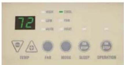
text_image
72 TEMP FAR MODE SLEEP OPERATION2900, 3900 and 5800 Series
Control Panel
*Dual-rated 230/208-volt units are shown with ratings separated by */. Units with single rating are 265-volt units.
Alphabetical Index
Category Page No.
Accessory List 56
Application Comments 20
Auxiliary Control Switches 12–13
Case Dimensions 21
Central Desk Control 14
Condensate Disposal Systems 34-36
Cooling/Heat Pump Performance Data 45
Ducted Installations 37-39
Dry Air 4
Electrical Connection 42
Essential Elements Ordering Overview 43
Exterior Grilles 40-41
Features and Benefits 9–11
Features Table 8
General Installation Suggestions 57-58
Heat Pumps and Energy Savings 18-19
Introduction to Zoneline ^® units 6
Latent System Capacity 46
Maximum Connected Load 44
Mini Specs 2900 2
Mini Specs 3900 2
Mini Specs 5800 2
Mini Specs Power Connection Kits and Nomenclature 3
Normal Yearly Operating Data 47
Remote Thermostat Control 15-17
Schematics 48-51
Specifications 55
Suggested Big Form Specifications 52–53
Table of Contents 5
Wall Case/Sub-Base Installation 22-33
Warranty 58
Zoneline System 7
Exterior Grille Color Samples

natural_image
Plain beige background with no visible text, symbols, or objectsWarm Gray Beige

natural_image
Solid brown rectangular background with no visible text, symbols, or patterns.Maple

natural_image
Solid dark brown rectangle with no visible text, symbols, or features.Bittersweet Chocolate
Colors may vary slightly due to printing process.

natural_image
Purple circular logo with a stylized white 'g' or 'e' symbol, no text or numbers present.100 years of innovation and we're just getting started
For more than a century, GE has been committed to producing innovative products that change the way people live. The result of thorough research and rigorous testing, GE appliances are designed for years of dependable performance.
Today, the GE tradition of quality and innovation continues.
GE Consumer & Industria
Appliances
General Electric Company
Louisville, KY 40225
geappliances.com
zoneline.com
Before purchasing an appliance, read important information about its estimated annual energy consumption or energy efficiency rating that is available from your retailer or geappliances.com.
GE has a policy of continuous improvement of its products and reserves the right to change materials and specifications without notice.
© 2009 GE Company
Pub. No. 20-S079 PC57416