A-128 - Module synthétiseur Doepfer - Free user manual and instructions
Find the device manual for free A-128 Doepfer in PDF.

User questions about A-128 Doepfer
0 question about this device. Answer the ones you know or ask your own.
Ask a new question about this device
Download the instructions for your Module synthétiseur in PDF format for free! Find your manual A-128 - Doepfer and take your electronic device back in hand. On this page are published all the documents necessary for the use of your device. A-128 by Doepfer.
USER MANUAL A-128 Doepfer
1. Introduction
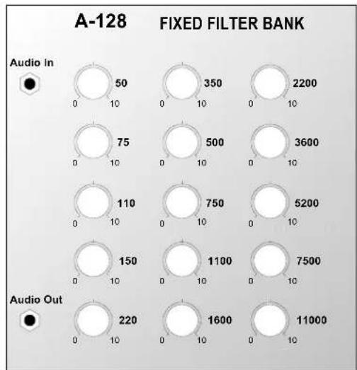
Module A-128 (Fixed Filter Bank) is a filter bank, made up of 15 parallel band pass filters, all with fixed middle frequencies and bandwidth:
50 Hz 350 Hz 2.2 kHz
75 Hz 500 Hz 3.6 kHz
110 Hz 750 Hz 5.2 kHz
150 Hz 1.1 kHz 7.5 kHz
220 Hz 1.6 kHz 11.0 kHz.
Each band pass filter has its own amplitude control knob, with which that frequency band can be attenuated. The bandwidth of each of the filters is approximately half an octave.
The signal at the output of the A-128 contains a mix of all the filters, depending on the position of each one's amplitude control knob.
The filter bank's main job is to emphasise individual sections of the whole audio frequency range. It's like a passive 15-band EQ.
2. A-128 - Overview
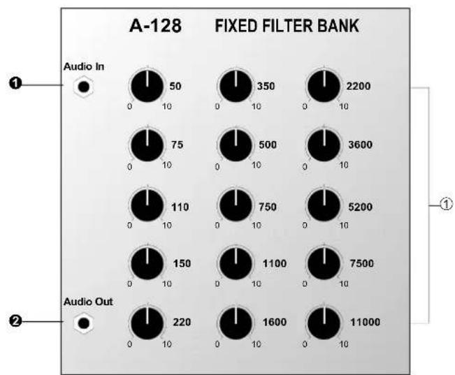
Controls:
① 50 ... 11000 : Amplitude controls (attenuators) for the individual band pass filters
In / Outputs:
① Audio In : Signal input
② Audio Out : Signal output
3. Controls
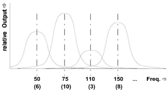
① Controls 50 Hz ... 11 kHz
With these controls you can set the amplitude of each of the 15 bandpass filters (see Fig. 1).
line
| Freq. | relative Output | |-------|-----------------| | 50 | (6) | | 75 | (10) | | 110 | (3) | | 150 | (8) |Fig. 1: The effect of different amplitude levels on the band pass filters.
4. In / Outputs
① Audio In
Socket ① is the filter bank's input, into which you patch the signal you want filtered.
② Audio Out
Output ② carries the signal filtered by the 15 band pass filters. The tonal quality will depend on the settings of the individual amplitude controls.
5. User examples
The main purpose of the Fixed Filter Bank is for changing the colour of an audio signal (including external signals that can be patched in via an A-119 module) by attenuating certain frequency bands. This is similar to an equalizer, except that an equalizer can also boost frequency bands, while the fixed filter bank only attenuates them.
Because each of the bands is very narrow (only about half an octave or a musical fifth) drastic tonal changes are possible - for instance 'telephone-voice' or vocoder-like effects.
Also, even with each band's amplitude control set to identical positions, a tonal change occurs (see Fig. 2); a neutral ‘straight-through’ setting isn't possible.
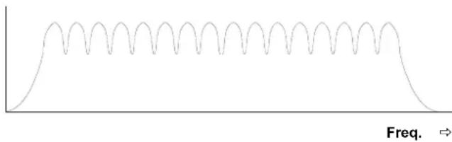
Fig. 2: Filter response with all controls fully up
Emphasising certain frequencies
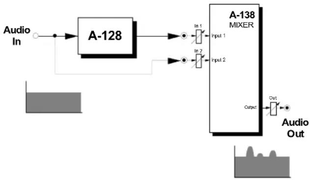
The patch in Fig. 3 shows how to emphasise certain frequencies using a filter bank.
The original signal and the output from the band pass filter are both patched into an A-138 mixer.
This patch is really a special case (with no attenuation) of the set-up on the following page.
flowchart
graph LR
    A["Audio In"] --> B["A-128"]
    B --> C["In 1 Input 1"]
    B --> D["In 2 Input 2"]
    C --> E["A-138 MIXER"]
    D --> E
    E --> F["Output"]
    G["Audio Out"] --> H["Output"]
Fig. 3: Emphasising certain frequencies
Creating a multi-band equalizer
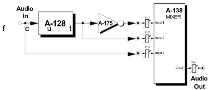
The patch in Fig. 4 shows how to model a simple graphic equalizer. An A-138 Mixer is used to mix the following signals:
- Input 1: the signal from the audio output of the filter bank, via an A-175 inverter.
- Input 2 : the signal from the audio output of the filter bank.
- Input 3: the original signal
Using the mixer pots "In 1", "In 2" and "In 3", you can control the relative mix of the signals :-
- In 1: A m o u n t o
• In 2: Amount of boost
• In 3: Amount of original signal
To model an equalizer, you adjust the mixer pots as per the above table. Naturally, any mix is possible, by adjusting the pots according to the following formula:
$$ \begin{array}{l} \text { Audio Out } = - \text { In } 1 \cdot \text { filter signal } \ + \ln 2 \cdot \text { filter signal } \ + \text { In } 3 \cdot \text { original signal } \ \end{array} $$
| Pot | just the original | just the filter bank | original + boost | original + cut |
| In 1 | 0 0 0 0 | ... 10 | ||
| In 2 | 0 10 0 | ... 10 0 | ||
| In 3 | 10 0 10 | 10 |

Patching a VCA in before the mixer's inputs can give voltage control of the relative amounts.
flowchart
graph LR
    f --> A1["Audio In"] --> A2["A-128 u t"]
    A2 --> A3["A-175"]
    A3 --> A4["A-138 MIXER"]
    A4 --> Out["Audio Out"]
    A3 --> In1["In 1"] --> In2["In 2"] --> In3["In 3"] --> In4["Output"]
    A3 --> In1b["Input 1"]
    A3 --> In2b["Input 2"]
    A3 --> In3b["Input 3"]
    A3 --> Outb["Output"]
    A2 --> In2b["Input 2"]
    A2 --> In3b["Input 3"]
    A2 --> In4b["Output"]
Fig. 4: Creating a multi-band equalizer
6. Patch-Sheet
The following diagrams of the module can help you recall your own Patches. They're designed so that a complete 19" rack of modules will fit onto an A4 sheet of paper.
Photocopy this page, and cut out the pictures of this and your other modules. You can then stick them onto another piece of paper, and create a diagram of your own system.
Make multiple copies of your composite diagram, and use them for remembering good patches and set-ups.

- Draw in patchleads with colored pens.
- Draw or write control settings in the little white circles.