A-163 - Module de synthétiseur Doepfer - Free user manual and instructions
Find the device manual for free A-163 Doepfer in PDF.

User questions about A-163 Doepfer
0 question about this device. Answer the ones you know or ask your own.
Ask a new question about this device
Download the instructions for your Module de synthétiseur in PDF format for free! Find your manual A-163 - Doepfer and take your electronic device back in hand. On this page are published all the documents necessary for the use of your device. A-163 by Doepfer.
USER MANUAL A-163 Doepfer
1. Introduction
Module A-163 is a voltage controlled audio frequency divider.
The frequency of the input signal (preferably the rectangle output of a VCO) is divided by an integer factor N (N = 1, 2, 3, 4 ... up to about 20). The output waveform is rectangle with 50% duty cycle.
The divisor N can be adjusted manually and modulated with an external control voltage (e.g. from LFO, ADSR, Random, MIDI-to-CV, Theremin, Light-to-CV, analog sequencer) with attenuator.
The following table shows the differences between the divider modules available in the A-100 system.
| A-115 A-113 | A-163 | ||
| Divisor setting | fixed manually voltage contr. | + manually | |
| Divisor range | 2, 4, 8, 16 1... | 24 integer | 1... 20 integer |
| No. of outputs | 4 (mixed) | 4 (mixed+single) | 1 |
| Output waveform | rectangle sawtooth rectangle | ||
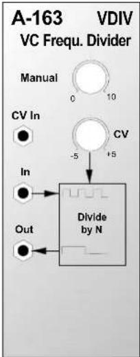
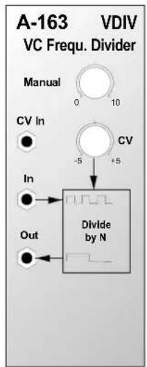
2. Overview
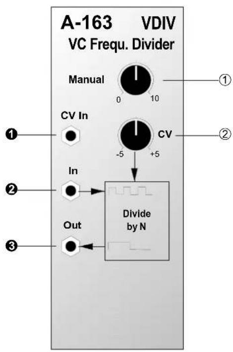
Controls:
① Manual: Control for manual setting of the integer dividing factor N
② CV : Symmetric (negative-0-positive) attenuator for control voltage at input ①
• fully clockwise: max. positive level
• middle position: level 0
- fully counterclockwise: max. negative level
For the first production series the inscription of the CV knob ② is wrongly 0...10 instead of -5...0...+5. The informations in this manual are correct, i.e. left stop = -5, middle position = 0, right stop = +5.
In- / Outputs:
① CV In : Control voltage input
② In: Audio input (preferably the rectangle output of a VCO or LFO), i.e. the master frequency for the divider
③ Out: Audio output of the frequency divider (rectangle)
3. Controls
① Manual
With knob ① the divisor N is manually adjusted. Integer division of an audio frequency leads to the so-called subharmonics. The table in fig. 1 shows the subharmonic frequencies and pitches of an audio signal C5 (= 523,2 Hz) as master frequency input for the A-163.
| Divisor | Freq. [Hz] | Pitch |
| 1 | 5 | 2^5 |
| 2 | 2 | 6^4 |
| 3 | 1 | 7^3 |
| 4 | 1 | 3^3 |
| 5 | 1 | 0^2 |
| 6 | 8 | ^27 |
| 7 | 7 | ^23 |
| 8 | 6 | ^25 |
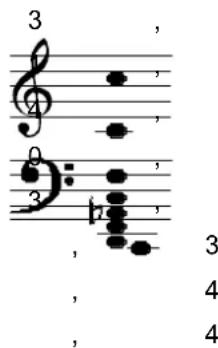
Fig. 1: Subharmonics of an audio signal with pitch C5 It becomes apparent that the subharmonics are equivalent to the tones of the minor chord scale.
The term "subharmonic" is not quite correct as the A-163 output waveform is rectangle with a marked harmonic spectrum in contrast to the "pure" sine waves used in the harmonics theory. For details concerning harmonic contents of different waveforms please refer to the A-110 or A-111 manual (VCO's). For details about subharmonics please refer to the A-113 manual.
② CV
The positive/negative attenuation and inversion of 2 the control voltage fed into socket ① is adjusted with 6 control ②. The following connections are valid :
| 6 | Position | Amplification | Effect |
| 8 | -5 | -1 inverted CV | |
| 8 | 0 | 0 A | full attenuation |
| F1 | original CV (not inverted) | ||

CThe manual setting of control ① and the external control voltage fed into socket ① and attenuated/inverted with control ② are internally added to generate the resulting control voltage that defines the divisor N.
4. In- / Outputs
① CV In
The external control voltage (e.g. from an LFO or ADSR) used to modulate the divisor N is fed into the CV input ①.
② In
Socket ② is the audio input of the module. This input is connected to the audio source (waveform preferable rectangle from an VCO or LFO). The frequency of this signal (= master frequency) is divided by N.
③ Out
Socket ③ is the output of the module. Here the subharmonic (rectangle) is available.
Frequency division of control signals
The output ③ of the module is AC-coupled. This means that no slow signals (e.g. 0.5 Hz LFO) can be divided. To obtain a DC-coupled output the capacitor C7 on the A-163 pc board has to be replaced by a jumper (short circuit). This modification leads to a 0/+5V rectangle output that can be used for slowly changing signals too. Please refer to the service manual for the position of C7.
5. User Examples
Sub-Oscillator
With the A-163 an audio sub-oscillator can be realized very simply. The rectangle output of a VCO is connected to the audio input of the A-163. The audio outputs of the VCO (e.g. sawtooth) and the A-163 are mixed together e.g. with an A-138b. Thus one obtains a VCO with sub-oscillator to enhance the bass sound of the VCO. The interval between VCO and sub-oscillator can be set manually or voltage controlled.
Subharmonic Glissando
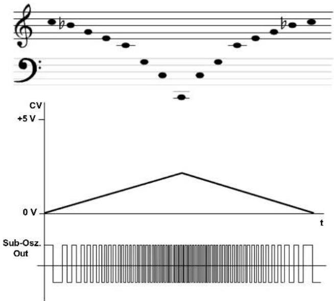
One obtains very interesting effects if a dynamically changing control voltage (e.g. from ADSR, LFO, Joy Stick, Theremin, Random or similar) is used to define the divisor N of the A-163. This leads to a special kind of glissandos containing only the subharmonics of the master frequency.
In fig. 1 the triangle signal of a LFO (e.g. A-145) is used to control the divisor N of the A-163. As only integer divisors occur both time and frequency quantization takes place. A so-called "subharmonic glissando" appears, i.e. separate tones with the same length are generated (subharmonics derived from the master frequency of the VCO signal).
line
| Time | CV | |------|--------| | 0 | 0 V | | t1 | ~2.5 V | | t2 | ~2.5 V | | t3 | ~2.5 V | | t4 | ~2.5 V | | t5 | ~2.5 V | | t6 | ~2.5 V | | t7 | ~2.5 V | | t8 | ~2.5 V | | t9 | ~2.5 V | | t10 | ~2.5 V | | t11 | ~2.5 V | | t12 | ~2.5 V | | t13 | ~2.5 V | | t14 | ~2.5 V | | t15 | ~2.5 V | | t16 | ~2.5 V | | t17 | ~2.5 V | | t18 | ~2.5 V | | t19 | ~2.5 V | | t20 | ~2.5 V | | t21 | ~2.5 V | | t22 | ~2.5 V | | t23 | ~2.5 V | | t24 | ~2.5 V | | t25 | ~2.5 V | | t26 | ~2.5 V | | t27 | ~2.5 V | | t28 | ~2.5 V | | t29 | ~2.5 V | | t30 | ~2.5 V | | t31 | ~2.5 V | | t32 | ~2.5 V | | t33 | ~2.5 V | | t34 | ~2.5 V | | t35 | ~2.5 V | | t36 | ~2.5 V | | t37 | ~2.5 V | | t38 | ~2.5 V | | t39 | ~2.5 V | | t40 | ~2.5 V | | t41 | ~2.5 V | | t42 | ~2.5 V | | t43 | ~2.5 V | | t44 | ~2.5 V | | t45 | ~2.5 V | | t46 | ~2.5 V | | t47 | ~2.5 V | | t48 | ~2.5 V | | t49 | ~2.5 V | | t50 | ~2.5 V | | t51 | ~2.5 V | | t52 | ~2.5 V | | t53 | ~2.5 V | | t54 | ~2.5 V | | t55 | ~2.5 V | | t56 | ~2.5 V | | t57 | ~2.5 V | | t58 | ~2.5 V | | t59 | ~2.5 V | | t60 | ~2.5 V | | t61 | ~2.5 V | | t62 | ~2.5 V | | t63 | ~2.5 V | | t64 | ~2.5 V | | t65 | ~2.5 V | | t66 | ~2.5 V | | t67 | ~2.5 V | | t68 | ~2.5 V | | t69 | ~2.5 V | | t70 | ~2.5 V | | t71 | ~2.5 V | | t72 | ~2.5 V | | t73 | ~2.5 V | | t74 | ~2.5 V | | t75 | ~2.5 V | | t76 | ~2.5 V | | t77 | ~2.5 V | | t78 | ~2.5 V | | t79 | ~2.5 V | | t80 | ~2.5 V | | t81 | ~2.5 V | | t82 | ~2.5 V | | t83 | ~2.5 V | | t84 | ~2.5 V | | t85 | ~2.5 V | | t86 | ~2.5 V | | t87 | ~2.5 V | | t88 | ~2.5 V | | t89 | ~2.5 V | | t90 | ~2.5 V | | t91 | ~2.5 V | | t92 | ~2.5 V | | t93 | ~2.5 V | | t94 | ~2.5 V | | t95 | ~2.5 V | | t96 | ~2.5 V | | t97 | ~2.5 V | | t98 | ~2.5 V | | t99 | ~2.5 V | | t100 | ~2.5 V |Fig. 1: Subharmonic glissando
Frequency Multiplication
In combination with the PLL module A-196 frequency multiplication can be obtained. For details refer to the A-196 manual.
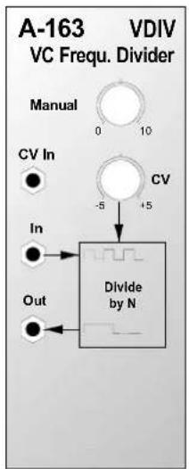
6. Patch-Sheet
The following diagrams of the module can help you recall your own Patches. They're designed so that a complete 19" rack of modules will fit onto an A4 sheet of paper.
Photocopy this page, and cut out the pictures of this and your other modules. You can then stick them onto another piece of paper, and create a diagram of your own system.
Make multiple copies of your composite diagram, and use them for remembering good patches and set-ups.

- Draw in patchleads with colored pens.
- Draw or write control settings in the little white circles.