
HDBASE100ME - Cable / Connectivity KanexPro - Free user manual and instructions
Find the device manual for free HDBASE100ME KanexPro in PDF.

| Product Type | HDBaseT Extender with 2-Port Ethernet Switch |
| Brand | KanexPro |
| Model | HDBASE100ME |
| Transmission Distance | Up to 330 ft (100 m) over single CAT6 cable |
| Supported Resolutions | 480i, 576i, 480p, 576p, 720p, 1080i, 1080p, 3D, 4K |
| Video Bandwidth | 10.2 Gbps |
| HDMI Standard | HDMI 1.4 with HDCP, CEC, EDID compliance |
| Audio Support | Dolby TrueHD, DTS Master Audio, LPCM |
| Ethernet | 2 Ethernet ports per unit, 10/100 Mbps adaptive |
| IR Control | IR input and output on both transmitter and receiver |
| RS232 Control | Bi-directional, 3-pin captive screw connector |
| Connectors | HDMI (IN/OUT), RJ-45, 3.5mm IR jacks, RS232, DC power |
| Power Supply | DC 5V, 3A adapter (6.5W consumption) |
| Chassis Material | Aluminum case with mounting ears |
| Dimensions (each unit) | 3.30 x 1.18 x 5.27 inches (84 x 30 x 134 mm) |
| Net Weight (each) | 1 lb (0.45 kg) |
| Operating Temperature | -20 to +60°C |
| Humidity | 10% to 90% |
| Warranty | 3 years |
| Package Contents | Transmitter, receiver, 2 power adapters, 2 IR emitters, 2 IR receivers, 2 RS232 cables, mounting ears, screws, user manual |
| Cleaning Instructions | Wipe with a dry soft cloth; do not use liquids or chemicals |
| Safety Precautions | Ensure proper grounding; do not open casing; use in ventilated area; disconnect power before servicing |
| Repairability | No user-serviceable parts; contact KanexPro support for repairs |
Frequently Asked Questions - HDBASE100ME KanexPro
User questions about HDBASE100ME KanexPro
0 question about this device. Answer the ones you know or ask your own.
Ask a new question about this device
Download the instructions for your Cable / Connectivity in PDF format for free! Find your manual HDBASE100ME - KanexPro and take your electronic device back in hand. On this page are published all the documents necessary for the use of your device. HDBASE100ME by KanexPro.
USER MANUAL HDBASE100ME KanexPro
HDBaseT® 100M Extender with 2-Port Ethernet Switch
Extend Ultra HD 4K, Multi-channel Audio, Ethernet & IR over a single Cat 6 cable
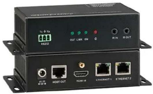
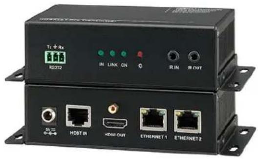
TABLE OF CONTENTS
- Introduction......1
1.1 Introduction to HDBASE100ME 1
1.2 Features....1
1.3 Package Contents.... 1
- Introduction of Product Appearance....2
2.1 Transmitter 2
2.2 Receiver....3
2.3 Twisted Pair Cable Connection....4
- System Connection ....4
3.1 System Diagram 4
3.2 Usage Precautions....5
3.3 Connection Procedure 5
3.4 System Applications....5
- Specification 6
- Panel Drawing....7
- Troubleshooting & Maintenance 8
- Safety Operation Guide......8
- Warranty....9
1. Introduction
1.1 Introduction to HDBASE100ME
The KanexPro HDBASE100ME is a transmitter-receiver set that enables you to routes Ultra high – definition signals up to 330 feet (100 meters). This extender also features two Ethernet ports on both the units, which can be used to connect standard network devices such as Apple TV's, network based media players, Smart TV's, 100Base-T routers, switches and hubs for LAN access.
Ideally used with Blu-ray players, game consoles, satellite boxes and HDMI based computers that require extension up to 330 feet connected to an HDTV or projector. Fully compliant with HDCP, EDID and DDC channels, this extender supports resolutions up to ultra HD 4K, 1080p & 3D.
The transmitter and receiver sets are built in to metal enclosure with sturdy finish with locking power HDMI connectors and power suppliers which protects the unit from dis-engament or signal loss.
1.2 Features
- Extend signals up to 330 ft. (100m) on single CAT6 cable
• Integrates 2-Ethernet ports for network devices
• Supports resolutions from 1080p/60@48bit to 4K
• Supports bandwidth up to 10.2 Gbps
• HDCP, CEC and EDID compliant - Infrared Signal Input/Output, embedded over extension
• Audio support: Dolby TrueHD & DTS Master Audio - Uncompressed audio support such as LPCM
- RS-232 Control
- Front panel-LEDs for link activity and HDCP authentication
- Locking HDMI connectors to avoid dis-engagement & signal loss
- Locking power connector
• Aluminum case with separate mounting ears.
Note: Please use a CAT5e cable with low impedance (Shielded twisted pair will be better and should be well grounded) for good transmission effect.
1.3 Package Contents
➢ 1 x HDMI Pro Transmitter
1 x HDMI Pro Receiver
➢ 4 x Mounting ears (Separated from the transmitter and the receiver)
➢ 2 x Power adapter (DC 5V, 3A)
2 x IR Emitter
2 x IR receiver
2 x RS232 cable
➢ 8 x Screws (3*6mm)
1 x User manual
2. Introduction of Product Appearance
2.1 Transmitter
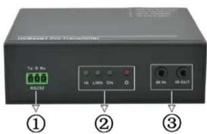
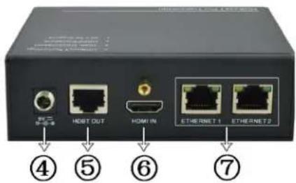
Figure 1 Appearance of the Transmitter
| No. | Name | Description |
| 1 | RS232 | Serial port, 3p captive screw connector, connect with the control terminal to control the controlled terminal, supports bi-directional RS232 control between the transmitter and the receiver. |
| 2 | HDCP Link Mode Power | √ HDCP: When connected with device, which supports HDCP and works normally, this LED will keep on. If the device does not support HDCP, the LED will blink.√ Link: Twisted Pair Link status indicator. It will keep on when connection is successful.√ Mode: Used to show the working status, blinks when in normal working state, turns off when stop working.√ Power: Turns red and keep on when power on. |
| 3 | IR IN&OUT | √ IN: Connect with IR receiver, the IR signal received from this port can only send out in the receiver.√ OUT: Connect with IR Emitter, and the sending IR signal is received from the receiver. |
| 4 | 5V DC | Connect with a DC 5V power adapter. |
| 5 | HDBase-T | To connect with the HDBASE100ME port of the receiver by using a single CAT5e cable (100m length in max). |
| 6 | HDMI IN | HDMI input port, connect with an HDMI source device. |
| 7 | ETHERNET | Ethenet ports, when need to work in a local area network, one of these 4 ports (both the Ethernet ports of the transmitter and the receiver) should be used for internet access, and the others can be connected with computers. If they are well connected, the yellow LED indicators on the corresponding ports will keep blink and the green ones will keep on when working. |
2.2 Receiver
The receiver is the one printed with "HDMI Pro Receiver" on the top panel.
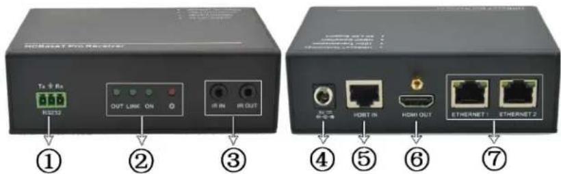
Figure 2 Appearance of the Receiver
| No. | Name | Description |
| 1 | RS232 | Serial port, 3p captive screw connector, connect with the control terminal to control the controlled terminal, supports bi-directional RS232 control between the transmitter and the receiver. |
| 2 | HDCP Link Mode Power | √ HDCP: When connected with device, which supports HDCP and works normally, this LED will keep on. If the device does not support HDCP, the LED will blink.√ Link: Twisted Pair Link status indicator. It will keep on when connection is successful.√ Mode: Used to show the working status, blinks when in normal working state, turns off when stop working.√ Power: Turns red and keep on when power on. |
| 3 | IR IN&OUT | √ IN: Connect with IR receiver, the IR signal received from this port can only send out in the transmitter.√ OUT: Connect with IR Emitter, and the sending IR signal is received from the transmitter. |
| 4 | 5V DC | Connect with a DC 5V power adapter. |
| 5 | HDBase-T | To connect with the HDBASE100ME port of the transmitter by using a single CAT5e cable (100m length in max). |
| 6 | HDMI OUT | HDMI output port, connect with an HDMI displaying device. |
| 7 | ETHERNET | Ethenet ports, when need to work in a local area network, one of these 4 ports (both the Ethernet ports of the transmitter and the receiver) should be used for internet access, and the others can be connected with computers. If they are well connected, the yellow LED indicators on the corresponding ports will keep blink and the green ones will keep on when working. |
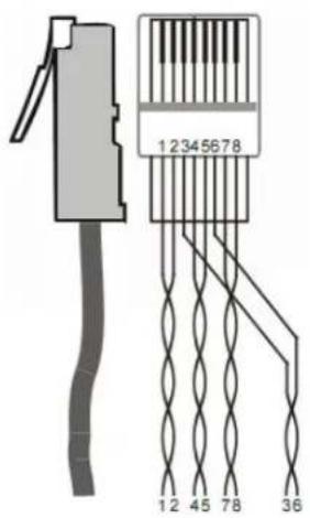
2.3 Twisted Pair Cable Connection & Termination Scheme
The twisted pair used in this extender MUST be a straight-through cable.
| TIA/EIA T568A | TIA/EIA T568B | |||
| Pin | Cable color | Pin | Cable color | |
| 1 | Green white | 1 | Orange white | |
| 2 | Green | 2 | Orange | |
| 3 | Orange white | 3 | Green white | |
| 4 | Blue | 4 | Blue | |
| 5 | Blue white | 5 | Blue white | |
| 6 | Orange | 6 | Green | |
| 7 | Brown white | 7 | Brown white | |
| 8 | Brown | 8 | Brown | |
| 1st Ground | 4--5 | 1st Ground | 4--5 | |
| 2nd Ground | 3--6 | 2nd Ground | 1--2 | |
| 3rd Group | 1--2 | 3rd Group | 3--6 | |
| 4th Group | 7--8 | 4th Group | 7--8 | |
- System Connection
3.1 System Diagram

flowchart
graph TD
    subgraph Transmitter
        PC1["PC1"] -->|Internet| Router
        Router -->|DVD| Transmitter
        Router -->|IR Emitter| Receiver
        Receiver -->|RS232| RS232
        RS232 -->|RS232 control signal| IR_Emitter
    end
    subgraph Receiver
        PC2["PC2"] -->|Internet| Router
        Router -->|HDTV| Transmitter
        Transmitter -->|IR Emitter| IR_Emitter
    end
    subgraph Internet
        PC3["PC3"] -->|Internet| Transmitter
        Transmitter -->|IR Emitter| IR_Emitter
    end
    PC1 -->|Internet| Transmitter
    PC2 -->|Internet| Transmitter
    PC3 -->|IR Emitter| Transmitter
    PC1 -->|Internet| Transmitter
    PC2 -->|Internet| Transmitter
    PC3 -->|IR Emitter| Transmitter
    PC1 -->|Internet| Transmitter
    PC2 -->|Internet| Transmitter
    PC3 -->|IR Emitter| Transmitter
    PC1 -->|Internet| Transmitter
    PC2 -->|Internet| Transmitter
    PC3 -->|IR Emitter| Transmitter
    PC2 -->|Internet| Transmitter
    PC1 -->|Internet| Transmitter
    PC2 -->|Internet| Transmitter
    PC3 -->|Internet| Transmitter
    PC1 -->|Internet| Transmitter
    PC2 -->|Internet| Transmitter
    PC3 -->|Internet| Transmitter
    PC1 -->|Internet| Transmitter
    PC2 -->|Internet| Transmitter
    PC3 -->|Internet| Transmitter
    PC1 -->|Internet| Transmitter
    PC2 -->|Internet| Transmitter
    PC3 -->|Internet| Transmitter
    PC2 -->|Internet| Transmitter
    PC1 -->|Internet| Transmitter
    PC2 -->|Internet| Transmitter
    PC3 -->|Internet| Transmitter
Figure 3 System Diagram
3.2 Usage Precautions
Please cut off the power of the HDMI source device and the output-displaying device before accessing with The HDBASE100ME, as it may damage to the extender. Ensure that all connections (including the power cord) are done before turning on the power to work with the extender.
3.3 Connection Procedure
Step1. Connect HDMI source (such as DVD player) to HDMI IN port of the transmitter with HDMI cable.
Step2. Connect HDBASE100ME port of the transmitter and HDBASE100ME port of the receiver, with single CAT5e cable.
Step3. Connect HDMI displayer (such as HDTV) to HDMI OUT port of the receiver with HDMI cable.
Step4. Both the transmitter and the receiver have IR IN and OUT. When one model use for IR signal receiver, the other model must send out the IR signal.
For example: When “IR IN” of the transmitter connects with an IR receiver, the IR Emitter must be connected to “IR OUT” of the receiver.
Step5. To set as a LAN, one of the four ETHERNET ports of the transmitter and the receiver should be used for Internet access, and the others can be connected with computers.
Step6. Connect the RS232 port of the computer and the RS232 port of the transmitter or the receiver (any one is able to work as the RS232 signal can be transmitted bi-directionally) by using a RS232 cable.
Step7. Connect DC5V power adaptors to both the transmitter and the receiver.
3.4 System Applications
The HDBASE100ME Extender can be widely used in many commercial A/V applications such as digital signage, hotels, restaurants, large screen displays and tradeshows, conference rooms, education, and banking institutions.
4. Specification
| Model Spec | Transmitter | Receiver |
| Input | ||
| Input Signal | 1 HDMI, 1 IR in | 1 IR in, 1 RJ-45 |
| Input Connector | 1 HDMI female1 3.5mm mini jack for IR in | 1 3.5mm mini jack for IR in1 RJ-45 |
| Video Signal | HDMI1.4 | TIA/EIA T568A or T568B |
| Audio | Digital audio, support HDMI audio transmitted through RGB or Y, Cr, Cb cable. | Digital audio, support HDMI audio transmitted through RGB or Y, Cr, Cb cable. |
| Output | ||
| Output | 1 RJ-45; 1 IR out | 1 HDMI; 1 IR out |
| Output Connector | 1 RJ-451 3.5mm mini jack for IR out | 1 HDMI female1 3.5mm mini jack for IR out |
| Video signal | TIA/EIA T568A or T568B | HDMI1.4 |
| Transmission Mode | HDBase-T, synchronous switching mode | |
| General | ||
| Resolution Range | 480i, 576i, 480p, 576p, 720p, 1080i, 1080p, 3D, 2k-4k | |
| Transmission Distance | Max distance 330 ft. (100m) | |
| Ethernet Transmission Speed | Adaptive 10M/100M, full duplex or half duplex. | |
| Gain | 0dB ~ 10dB@100MHz | |
| Differential Phase Error | ±10° @ 135MHz_100M | |
| SNR | >70dB@ 100MHz-100M | |
| Bandwidth | 10.2Gbps | |
| Return Lost | <-30dB@5KHz | |
| THD | <0.005%@1KHz | |
| HDMI Standard | Support HDMI1.4 and HDCP | |
| Min. ~Max. Level | <0.3V ~ 1.45Vp-p | |
| Impedance | 75Ω | |
| Temperature | 20 ~ +60 C | |
| Humidity | 10% ~ 90% | |
| Power Supply /Consumption | DC 5V power adapter, 6.5W | |
| Chassis Dimension | W3.30" x H1.18" x D5.27 | W3.30" x H1.18" x D5.27 |
| Net Weight | 1 lb. | 1 lb. |
5. Panel Drawing
Transmitter

Figure 4 Panel Drawing of Transmitter
Receiver

Figure 5 Panel Drawing of Receiver
6. Troubleshooting & Maintenance
1) When there is a color lost or no video signal output, check HDMI & Cat5e cables or try different cables.
2) When you can't control the extender by computer through its COM port, please check the COM port number in the software, and make sure the COM port is in good condition and the communication protocol is correct.
3) When switching, there is no output image:
- Check if there is any signal at the input.
- Check if there is any signal at the output.
We can check these by using an oscilloscope or a multimeter. If there is no signal input/output, maybe the input/output cables broken or the connectors are loose.
- Check if the output port number is the same with the controlled one.
- If it is still the same after the above troubleshooting please contact technical support.
4) If the static becomes stronger when connecting the video connectors, it probably due to bad grounding, please check the grounding and make sure it connected well, otherwise it would damage the extender.
5) If the extender cannot be controlled through the RS232 port or by the IR remote, the unit could be malfunctioning. Please contact support
7. Safety Operation Guide
In order to guarantee the reliable operation of the equipment and safety of the staff, please abide by the following proceeding in installation, using and maintenance:
1) The system must be earthed properly. Do not use two blades plugs and ensure the alternating power supply ranged from 100v to 240v and from 50Hz to 60Hz.
2) Do not put the device in a place of too hot or too cold.
3) As the power generating heat when running, the working environment should be maintained fine ventilation, in case of damage caused by overheat.
4) Cut off the general power switch in humid weather or left unused for long time.
5) Before following operation, ensure that the alternating current wire is pull out of the power supply:
● Take off or reship any components of the equipment.
● Take off or rejoin any pin or other link of the equipment.
6) As to non-professional or without permission, please DO NOT try to open the casing of the equipment, DO NOT repair it on your own, in case of accident or increasing the damage of the equipment.
7) DO NOT splash any chemicals substance or liquid in the equipment or around.
8. Warranty
KanexPro TM warrants that (a) its products (the "Product") will perform greatly in agreement with the accompanying written materials for a period of 36 months from the date of receipt (3 years) and (b) that the product will be free from defects in materials and workmanship under normal use and service for a period of 3 years.
B. CUSTOMER REMEDIES
KanexPro's entire liability and Customer's exclusive remedy shall be, at KanexPro option, either return of the price paid for the product, or repair or replacement of the Product that does not meet this Limited Warranty and which is returned to KanexPro with a copy of customers' receipt. This Limited Warranty is void if failure of the Product has resulted from accident, abuse, or misapplication. Any replacement Product will be warranted for the remainder of the original warranty period of 3 years, whichever is longer.
C. NO OTHER WARRANTIES
TO THE MAXIMUM EXTENT PERMITTED BY APPLICABLE LAW, KANEX DISCLAIMS ALL OTHER WARRANTIES, EITHER EXPRESS OR IMPLIED, INCLUDING, BUT NOT LIMITED TO IMPLIED WARRANTIES OF MERCHANTABILITY AND FITNESS FOR A PARTICULAR PURPOSE, WITH REGARD TO THE PRODUCT AND ANY RELATED WRITTEN MATERIALS. THIS LIMITED WARRANTY GIVES CUSTOMERS SPECIFIC LEGAL RIGHTS. CUSTOMERS MAY HAVE OTHER RIGHTS DEPENDING ON THE JURISDICTION.
D. NO LIABILITY FOR DAMAGES
TO THE MAXIMUM EXTENT PERMITTED BY APPLICABLE LAW, IN NO EVENT SHALL KANEX BE LIABLE FOR ANY DAMAGES WHATSOEVER (INCLUDING WITHOUT LIMITATION, SPECIAL, INCIDENTAL, CONSEQUENTIAL, OR INDIRECT DAMAGES FOR PERSONAL INJURY, LOSS OF BUSINESS PROFITS, BUSINESS INTERRUPTION, LOSS OF BUSINESS INFORMATION, OR ANY OTHER PECUNIARY LOSS) ARISING OUT OF THE USE OF OR INABILITY TO USE THIS PRODUCT, EVEN IF KANEX HAS BEEN ADVISED OF THE POSSIBILITY OF SUCH DAMAGES.
KanexPro™
Brea, California
KanexPro.com
MPN: HDBASE100ME
HDMI are trademarks or registered trademarks of HDMI Licensing LLC in the United States and other countries. Kanex is a trademark of Apogee Inc., registered in the U.S.
- TABLE OF CONTENTS
- Introduction
- Introduction to HDBASE100ME
- Features
- Package Contents
- Introduction of Product Appearance
- Transmitter
- Receiver
- Twisted Pair Cable Connection & Termination Scheme
- System Diagram
- Usage Precautions
- Connection Procedure
- System Applications
- Specification
- Panel Drawing
- Troubleshooting & Maintenance
- Safety Operation Guide
- Warranty
- CUSTOMER REMEDIES
- NO OTHER WARRANTIES
- NO LIABILITY FOR DAMAGES
Brand : KanexPro
Model : HDBASE100ME
Category : Cable / Connectivity