Trove3SH3 - Access Control System Altronix - Free user manual and instructions
Find the device manual for free Trove3SH3 Altronix in PDF.


| Product Type | Access Control System Enclosure with Power Integration |
| Model | Trove3SH3 |
| Brand | Altronix |
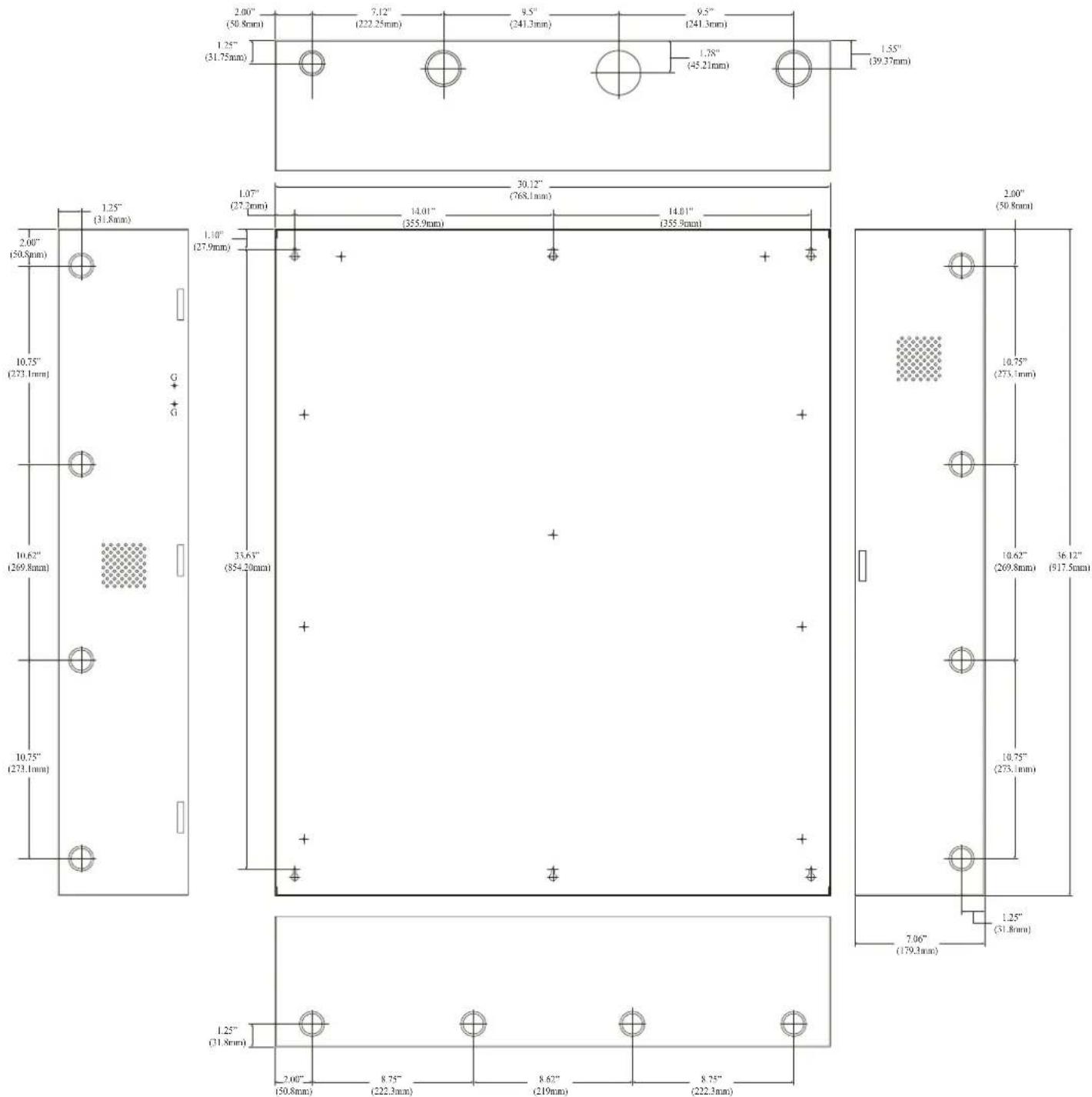
| Enclosure Dimensions | 36.12" x 30.125" x 7.06" (917.5mm x 768.1mm x 179.3mm) |
| Backplane Compatibility | Software House (SH) access controllers with Altronix power supplies and accessories |
| Input Voltage | 115VAC/120VAC, 60Hz |
| Output Voltage Options | 12VDC or 24VDC (selectable via SW1 on certain power supplies) |
| Maximum Output Current | Up to 10A continuous (dependent on power supply module) |
| Battery Backup | Up to four (4) 12VDC/12AH batteries |
| Agency Listings | UL 294 (6th edition), ULC-S319, CE, Canadian ICES-003 |
| Environmental Rating | Humidity: 85% (UL) / 93% (ULC); Temperature: 30°C (UL) / 32°C (ULC) |
| Enclosure Material | 16 Gauge steel with ample knockouts |
| Tamper Switch | UL Listed tamper switch (Altronix TS112 or equivalent) included |
| Wiring Requirements | 14 AWG or larger for power connections; keep power-limited and non power-limited wiring separate with 0.25" spacing |
| Power Supply Options | AL400ULXB2, AL600ULXB, AL1012ULXB, AL1024ULXB2, eFlow4NB, eFlow6NB, eFlow102NB, eFlow104NB |
| Sub-Assembly Modules | ACM4(CB), ACM8(CB), ACMS8(CB), MOM5, PD4UL(CB), PD8UL(CB), PD16W(CB), PDS8(CB), VR6, LINQ2 |
| LINQ2 Network Module | Optional remote IP monitoring and control of eFlow power supplies |
| Installation | Indoor use only; mount to wall using keyholes; connect ground and AC power |
| Maintenance | Annual output voltage and battery test; replace batteries every 4-5 years |
| Warranty | Refer to Altronix warranty; product specifications subject to change |
Frequently Asked Questions - Trove3SH3 Altronix
User questions about Trove3SH3 Altronix
0 question about this device. Answer the ones you know or ask your own.
Ask a new question about this device
Download the instructions for your Access Control System in PDF format for free! Find your manual Trove3SH3 - Altronix and take your electronic device back in hand. On this page are published all the documents necessary for the use of your device. Trove3SH3 by Altronix.
USER MANUAL Trove3SH3 Altronix
Access & Power Integration
SECURITY

LISTED
SECURITY

LISTED
SIGNALING

LISTED

Combine Altronix Power and Accessories with
Access Controllers from the Industry's Leading Manufacturers
Installation Guide

Altronix®
All registered trademarks are property of their respective owners. More than just power. ^TM
Rev. 101817
Installing Company: ____ Service Rep. Name: ____
Address: ____ Phone #: ____
Overview:
Trove accommodates various combinations of access controllers and accessories from the industry's leading manufacturers with or without Altronix power supplies and accessories for access systems. A variety of backplanes offer a wide range of scalable access and power configurations. Trove simplifies board layout and wire management, while reducing installation and labor costs.
Trove Model Identification:
| Series | TroveEnclosure Size | Backplane Model(Access Controller Manufacturer) | Backplane Size |
| Trove | 118" x 14.5" x 4.625"(457mm x 368mm x 118mm) | C = CDVI | 116.625" x 12.5" x 0.06"(422.3mm x 317.5mm x 1.5mm) |
| BV = Brivo | 116.625" x 12.5" x 0.3125"(422.3mm x 317.5mm x 7.9mm) | ||
| DM = DMP | |||
| JC = Johnson Controls | |||
| M = Mercury | |||
| PD = ProdataKey | |||
| SA = Salto | |||
| V = HID/VertX | |||
| 227.25" x 21.75" x 6.5"(692.2mm x 552.5mm x 165.1mm) | AM = AMAG | 225.375" x 19.375" x 0.3125"(644.5mm x 492.1mm x 7.9mm) | |
| AG = AMAG | |||
| BH = Bosch | |||
| BL = Universal Blank Backplane | |||
| BV = Brivo | |||
| CV = CDVI | |||
| DM = DMP* | |||
| HN = Honeywell NctAXS | |||
| HW = Honeywell ProWatch/WinPak | |||
| JC = Johnson Controls | |||
| KA = Keyscan | |||
| KII = Kantech | |||
| M = Mercury | |||
| PX = Paxton* | |||
| SA = Salto* | |||
| SH = Software House | |||
| SL = Sielox* | |||
| V = HID/VertX | |||
| Z = ZKTeco | |||
| 336.12" x 30.125" x 7.06"(917.5mm x 768.1mm x 179.3mm) | BL = Universal Blank Backplane | 334.0" x 28.0" x 0.3125"(863.6mm x 711.2mm x 7.9mm) | |
| BV = Brivo | |||
| CV = CDVI | |||
| HW = Honeywell ProWatch/WinPak | |||
| JC = Johnson Controls | |||
| M = Mercury | |||
| SH = Software House | |||
| V = HID/VertX |
Door Backplanes for System Expansion:
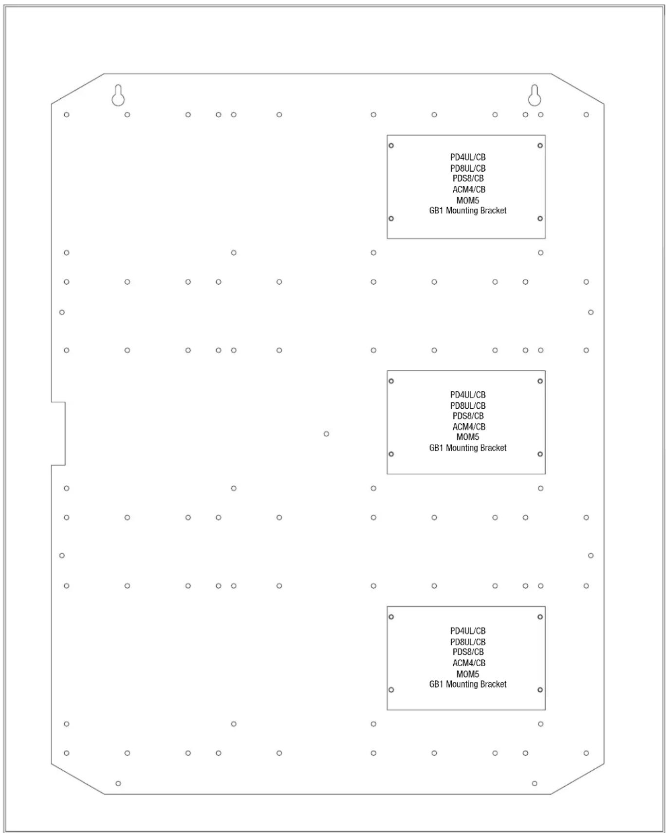
TMV2 - Trove2 and Trove3 door backplane compatible with Mercury or HID/VertX boards and Altronix sub-assemblies (Fig. 11, pg. 13). THWD2 - Trove2 and Trove3 door backplane compatible with Honeywell ProWatch/WinPak boards.
Specifications:
Agency Listings:
- UL 294 - 6th edition. Trove1 and Trove2 Power Controllers: Line Security I, Destructive Attack I, Endurance IV, Stand-by Power II.
- This Class B digital apparatus complies with Canadian ICES-003.
• CE European Conformity.
Environmental:
- Humidity and Temperature conditions as tested by UL (85%, +/-5% @ 30°C +/-2°C), ULC (93%, +/-2% @ 32°C +/-2°C).
Specifications:
Battery Backup:
- Trovel enclosure accommodates up to two (2) 12VDC/7AH batteries.
- Trove2 enclosure accommodates up to four (4) 12VDC/12AH batteries.
- Trove3 enclosure accommodates up to four (4) 12VDC/12AH batteries.
Additional Features:
- 16 Gauge enclosure with ample knockouts for convenient access.
Installation Instructions:
- Remove backplane from enclosure. Do not discard hardware.
- Mark and predrill holes in the wall to line up with the top two/three keyholes in the enclosure. Install two/three upper fasteners and screws in the wall with the screw heads protruding. Place the enclosure's upper keyholes over the two/three upper screws; level and secure. Mark the position of the lower holes. Remove the enclosure. Drill the lower holes and install the two/three fasteners. Place the enclosure's upper keyholes over the two/three upper screws. Install the two/three lower screws and make sure to tighten all screws (refer to enclosure drawings pages 18-20).
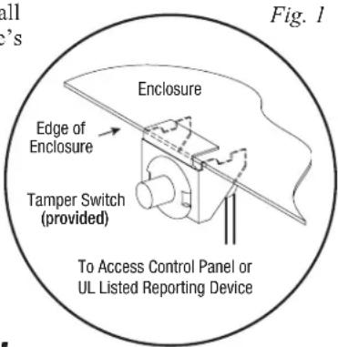
- Mount included UL Listed tamper switch (Altronix Model TS112 or equivalent) in desired location, opposite hinge. Slide the tamper switch bracket onto the edge of the enclosure approximately 2" from the right side (Fig. 1, pg. 3). Connect tamper switch wiring to the Access Control Panel input or the appropriate UL Listed reporting device.
To activate alarm signal open the door of the enclosure.
- Mount boards to backplane, refer to individual Trove installation instructions.
Power Supply Sub-Assembly Specifications:
| Altronix Power Supply | Input Rating Output Rating | Battery Size for 30 min. Backup | Refer to | |
| AL400ULXB2 115VAC | , 60Hz, 3.5A 12VDC @ 4A or 24VDC @ 3A 4AH | ULXB Installation InstructionsRev. ULXB-020419 | ||
| AL600ULXB 115VAC, | 60Hz, 3.5A 12VDC or 24VDC @ 6A 7AH | |||
| AL1012ULXB 115VAC | , 60Hz, 2.6A 12VDC @ 10A 12AH | |||
| AL1024ULXB2 115VAC | , 60Hz, 4.2A 24VDC @ 10A 12AH | |||
| eFlow4NB* | 120VAC, 60Hz, 3.5A 12VDC or 24VDC @ 4A 4AH | eFlow Installation InstructionsRev. EFNB-021319 | ||
| eFlow6NB* | 120VAC, 60Hz, 3.5A 12VDC or 24VDC @ 6A 7AH | |||
| eFlow102NB* | 120VAC, 60Hz, 3.5A 12VDC @ 10A 12AH | |||
| eFlow104NB* | 120VAC, 60Hz, 4.5A 24VDC @ 10A 12AH |
* LINQ2 can be installed when utilizing eFlow power supply/charger boards.
Sub-Assembly Specifications:
| Altronix UL Listed Sub-Assembly | Description | Current Draw | Refer to |
| ACM4(CB) | 4 Fused (or PTC) Output Access Power Controller | 12VDC @ 0.4A max. or 24VDC @ 0.2A max. | ACM4/ACM4CB Installation Instructions Rev. 052819 |
| ACM8(CB) | 8 Fused (or PTC) Output Access Power Controller | 12VDC @ 0.6A max. or 24VDC @ 0.3A max. | ACM8/ACM8CB Installation Instructions Rev. 031819 |
| ACMS8(CB) | 8 Fused (or PTC) Output Access Power Controller | 12VDC @ 0.6A max. or 24VDC @ 0.3A max. | ACMS8/ACMS8CB Installation Instructions Rev. 090518 |
| MOM5 | 5 PTC Output Power Distribution Module with Fire Alarm Interface | 12-24VDC 55mA max. | MOM5 Installation Instructions Rev. 020119 |
| PD4UL(CB) | 4 Fused (or PTC) Output Power Distribution Module | N/A | PD4UL Installation Instructions Rev. 020119 |
| PD4ULCB Installation Instructions Rev. 020119 | |||
| PD8UL(CB) | 8 Fused (or PTC) Output Power Distribution Module | N/A | PD8UL Installation Instructions Rev. 020119 |
| PD8ULCB Installation Instructions Rev. 020119 | |||
| PD16W(CB) | 16 Fused (or PTC) Output Power Distribution Module | N/A | PD16W/PD16WCB Installation Instructions Rev. 020119 |
| PDS8(CB) | 8 Fused (or PTC) Dual Input Power Distribution Module | N/A | PDS8/PDS8CB Installation Instructions Rev. 070116 |
| VR6 | Voltage Regulator | 24VDC @ 1.75A or 3.5A Output: 5VDC or 12VDC @ 6A | VR6 Installation Instructions Rev. 050517 |
| LINQ2* | Network Communication Module | 12-24VDC 100mA max. | LINQ2 Installation Instructions Rev. 060514 |
* LINQ2 can be installed when utilizing eFlow power supply/charger boards.
Installation Instructions:
Wiring methods shall be in accordance with the National Electrical Code/NFPA 70/ANSI, CSA C22.1, Canadian Electrical Code, Part I, Safety Standard for Electrical Installations, Part I, and with all local codes and authorities having jurisdiction.
Product is intended for indoor use only, within the protected or restricted area.
- The power supply is pre-wired to the ground (chassis). Connect main incoming ground to the provided green grounding conductor lead. Connect unswitched AC power (115VAC/120VAC 60Hz) to the terminals marked [L, N] on a single or both power supply boards. Use 14 AWG or larger for all power connections.
Keep power-limited wiring separate from non power-limited wiring.
Minimum 0.25" spacing must be provided (Figs. 5-12, pgs. 7-14).
CAUTION: Do not touch exposed metal parts. Shut branch circuit power before installing or servicing equipment.
There are no user serviceable parts inside. Refer installation and servicing to qualified service personnel.
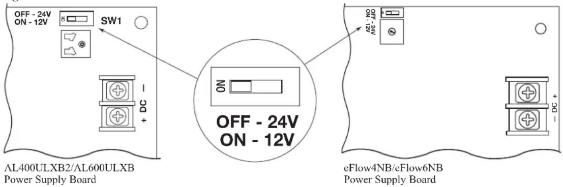
- Select desired DC output voltage by setting SW1 to the appropriate position on the AL400ULXB2, AL600ULXB, eFlow4NB, and eFlow6NB power supply (Fig. 2, pg. 4). AL1012ULXB and eFlow102NB power supplies are factory set at 12VDC and AL1024ULXB2 and eFlow104NB power supplies are factory set at 24VDC.
- Measure the output voltage of the unit before connecting any devices to ensure proper operation. Improper or high voltage will damage these devices (Figs. 3d, 4h, pg. 6, Figs. 5-10, pgs. 7-12, Fig. 12, pg. 14).
- Connect devices or Altronix sub-assembly modules to be powered to the terminals marked [-DC +]
(Figs. 3d, 4h, pg. 6, Figs. 5-10, pgs. 7-12, Fig. 12, pg. 14).
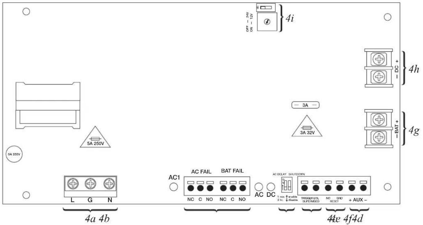
eFlow Power Supply: For auxiliary device connection, this output will not be affected by Low Power Disconnect or Fire Alarm Interface. Connect device to the terminals marked [+ AUX -] (Fig. 3f, pg. 6, Figs. 5-12, pgs. 7-14).
-
For Access Control applications batteries are optional. Batteries are not optional for ULC-S319. Capacity capable of providing 30 minutes of stand-by is required (See Power Supply Specifications, Pg. 3). When batteries are not used, a loss of AC will result in the loss of output voltage. When the use of stand-by batteries is desired, they must be lead acid. Connect battery to the terminals marked [-BAT +]. Use two (2) 12VDC batteries connected in series for 24VDC operation (battery leads included) (Figs. 3c, 4g, pg. 6, Figs. 5-10, pgs. 7-12, Fig. 12, pg. 14). Use batteries - Casil CL1270 (12V/7AH), CL12120 (12V/12AH) batteries or UL recognized BAZR2 batteries of an appropriate rating.
-
Connect appropriate signaling notification devices to AC FAIL & BAT FAIL supervisory relay outputs (Figs. 3b, 4b, pg. 6, Figs. 5-10, pgs. 7-12, Fig. 12, pg. 14).
For eFlow Power Supply/Chargers (steps 7-10):
- To delay AC reporting for 2 hrs., set dip switch [AC Delay] to OFF position (Fig. 4c, pg. 6, Figs. 5-10, pgs. 7-12, Fig. 12, pg. 14). To delay AC reporting for 1 min., set dip switch [AC Delay] to ON position (Fig. 4c, pg. 6, Figs. 5-10, pgs. 7-12, Fig. 12, pg. 14). Note: Must be set to ON position for Burglar Alarm Applications.
- To enable Fire Alarm Disconnect set dip switch [Shutdown] to ON position (Fig. 4c, pg. 6, Figs. 5-10, pgs. 7-12, Fig. 12, pg. 14). To disable Fire Alarm Disconnect set dip switch [Shutdown] to OFF position (Fig. 4c, pg. 6, Figs. 5-10, pgs. 7-12, Fig. 12, pg. 14).
- Trigger terminals are end of a line resistor supervised (10k ohms). Opening or shorting trigger terminals will cause [DC] output to shutdown (Fig. 4d, pg. 6, Figs. 5-10, pgs. 7-12, Fig. 12, pg. 14).
- Place a jumper for non-latching FACP. A momentary short on these terminals resets FACP latching [Trigger EOL Shutdown] (Fig. 4d, pg. 6, Figs. 5-10, pgs. 7-12, Fig. 12, pg. 14).
- Please ensure that the cover is secured with the provided key lock.
Power Supply Board Output Voltage Settings:
Fig. 2
Terminal Identification:
| Terminal Legend Function | Description |
| L, G, N | Connect 115VAC/120VAC 60Hz to these terminals: L to hot, N to neutral, G to ground (non power-limited) (ULXB - Fig. 3a, pg. 6, eFlow - Fig. 4a, pg. 6). |
| - DC + | AL300ULXB2 - 12VDC or 24VDC @ 2.5A continuous output (power-limited output) (Fig. 3d, pg. 6).AL400ULXB2 - 12VDC @ 4A or 24VDC @ 3A continuous output (power-limited output) (Fig. 3d, pg. 6).AL600ULXB - 12VDC or 24VDC @ 6A continuous output (non power-limited output) (Fig. 3d, pg. 6).AL1012ULXB - 12VDC @ 10A continuous output (non power-limited output) (Fig. 3d, pg. 6).AL1024ULXB2 - 24VDC @ 10A continuous output (non power-limited output) (Fig. 3d, pg. 6).cFlow3NB - 12VDC or 24VDC @ 2A continuous output (power-limited output) (Fig. 4h, pg. 6).cFlow4NB - 12VDC or 24VDC @ 4A continuous output (power-limited output) (Fig. 4h, pg. 6).cFlow6NB - 12VDC or 24VDC @ 6A continuous output (non power-limited output) (Fig. 4h, pg. 6).cFlow102NB - 12VDC @ 10A continuous output (non power-limited output) (Fig. 4h, pg. 6).cFlow104NB - 24VDC @ 10A continuous output (non power-limited output) (Fig. 4h, pg. 6). |
| Trigger EOL Supervised (eFlow only) | Fire Alarm Interface trigger input from a short or FACP. Trigger inputs can be normally open, normally closed from an FACP output circuit (Power-Limited input) (Fig. 4d, pg. 6). |
| NO, GND RESET (eFlow only) | FACP interface latching or non-latching (Power-Limited) (Fig. 4c, pg. 6). |
| + AUX - (eFlow only) | Auxiliary Power-Limited output rated @ 1A (unswitched) (Power-Limited output) (Fig. 4f, pg. 6). |
| AC FailNC, C, NO | Indicates loss of AC power, c.g. connect to audible device or alarm panel. Relay normally energized when AC power is present. Contact rating 1A @ 30VDC (Power-Limited) (Figs. 3b, 4b, pg. 6). |
| Bat FailNC, C, NO | Indicates low battery condition, e.g. connect to alarm panel. Relay normally energized when DC power is present. Contact rating 1A @ 30VDC. A removed battery is reported within 5 minutes.Battery reconnection is reported within 1 minute (Power-Limited) (Figs. 3b, 4b, pg. 6). |
| - BAT + | Stand-by battery connections (non power-limited) (Figs. 3c, 4g, pg. 6).AL300ULXB2, AL400ULXB2, AL600ULXB and AL1012ULXB - maximum charge current 0.7A.AL1024ULXB2 - maximum charge current 3.6A.eFlow - maximum charge current 1.54A.Note: Expected battery life is 5 years; however, it is recommended changing batteries in 4 years or less if needed. |
Maintenance:
Unit should be tested at least once a year for the proper operation as follows:
Output Voltage Test: Under normal load conditions, the DC output voltage should be checked for proper voltage level.
Battery Test: Under normal load conditions check that the battery is fully charged, check specified voltage (12VDC @ 13.2 or 24VDC @ 26.4) both at the battery terminal and at the board terminals marked [-BAT+] to ensure that there is no break in the battery connection wires.
Replacing Batteries: Disconnect existing batteries. Connect battery to the terminals marked [-BAT +] . Use two (2) 12VDC batteries connected in series for 24VDC operation.
Fig. 3 - ULXB configuration
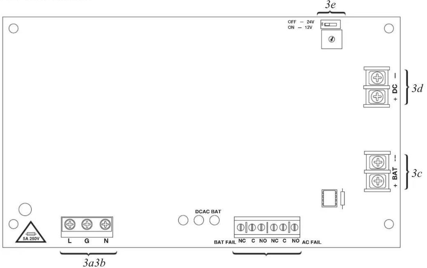
Fig. 4 - eFlowNB configuration
Trove1 Power Distribution Modules Configuration:
Fig. 5
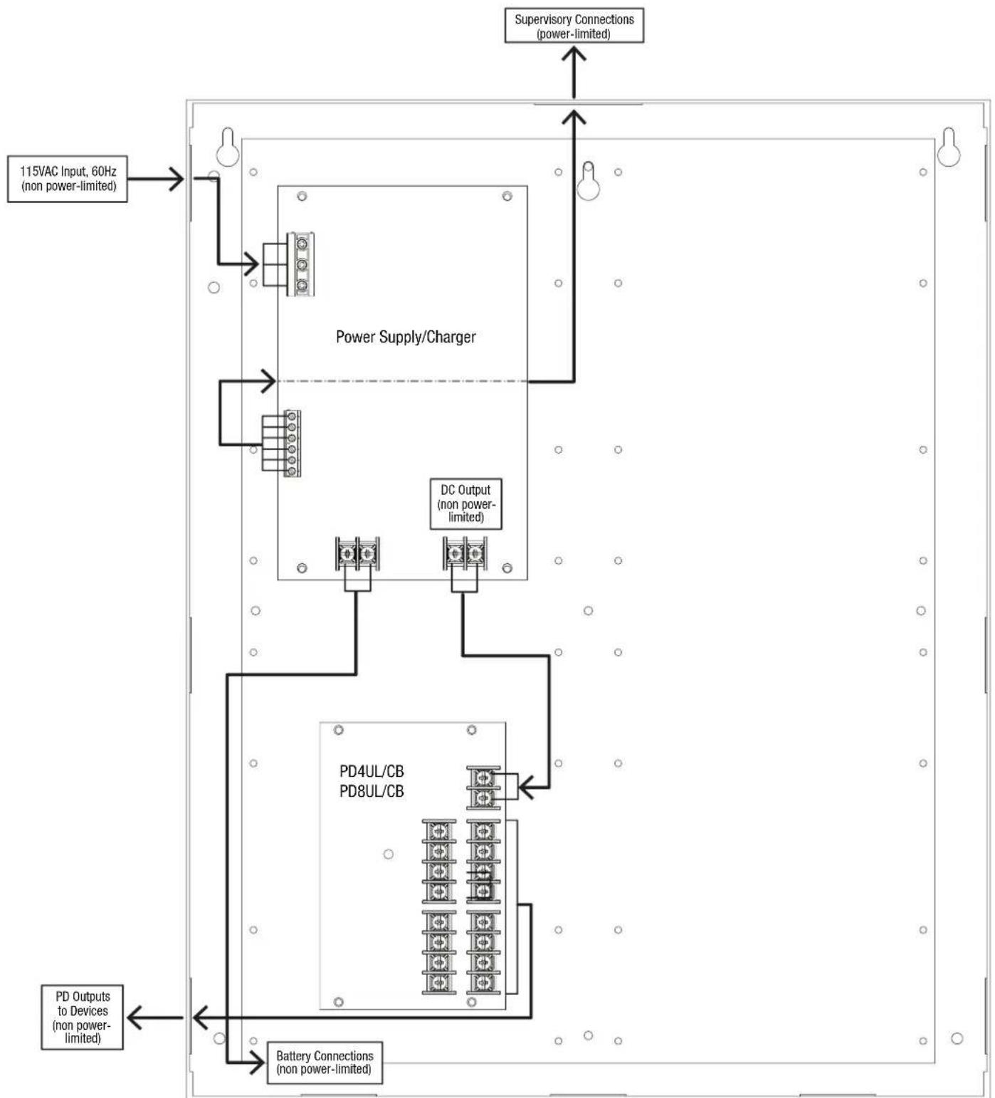
flowchart
graph TD
    A["115VAC Input, 60Hz (non power-limited)"] --> B["Power Supply/Charger"]
    B --> C["DC Output (non power-limited)"]
    C --> D["PD4UL/CB PD8UL/CB"]
    D --> E["Battery Connections (non power-limited)"]
    E --> F["PD Outputs to Devices (non power-limited)"]
    G["Supervisory Connections (power-limited)"] --> B
    G --> C
    G --> D
Trove1 MOM5 Configuration:
Fig. 6
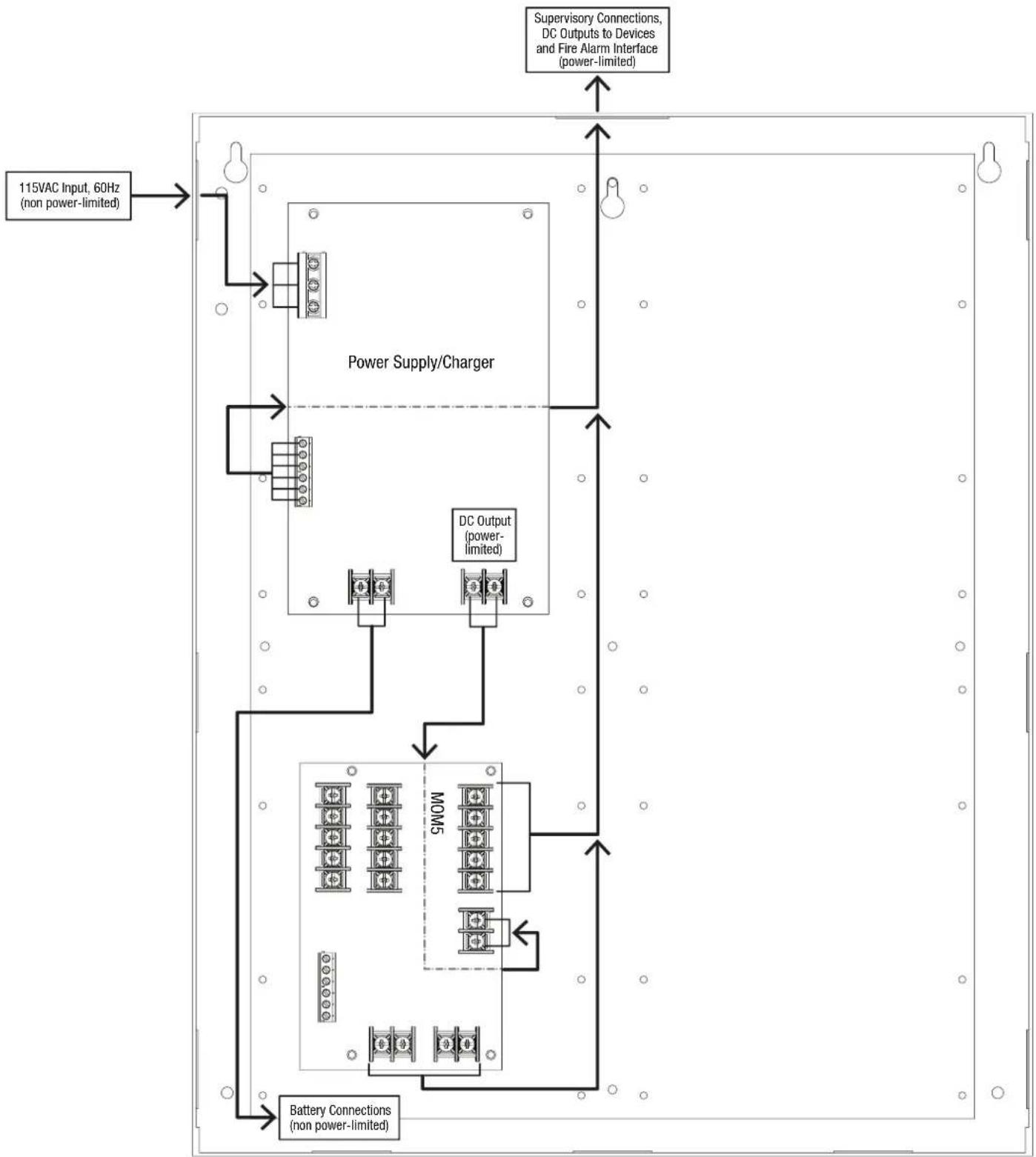
flowchart
graph TD
    A["115VAC Input, 60Hz (non power-limited)"] --> B["Power Supply/Charger"]
    B --> C["DC Output (power-limited)"]
    C --> D["MOM5"]
    D --> E["Battery Connections (non power-limited)"]
    F["Supervisory Connections, DC Outputs to Devices and Fire Alarm Interface (power-limited)"] --> B
    F --> C
    F --> D
    F --> E
Trove1 ACM4(CB) Configuration:
Fig. 7
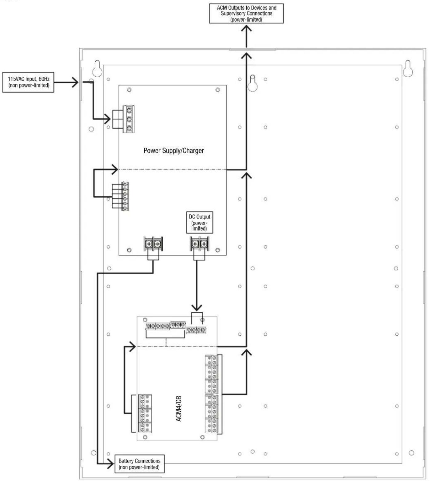
flowchart
graph TD
    A["115VAC Input, 60Hz (non power-limited)"] --> B["Power Supply/Charger"]
    B --> C["DC Output (power-limited)"]
    C --> D["ACM4/CB"]
    D --> E["Battery Connections (non power-limited)"]
    F["ACM Outputs to Devices and Supervisory Connections (power-limited)"] --> B
Trove2 Power Distribution Modules Configuration:
Fig. 8
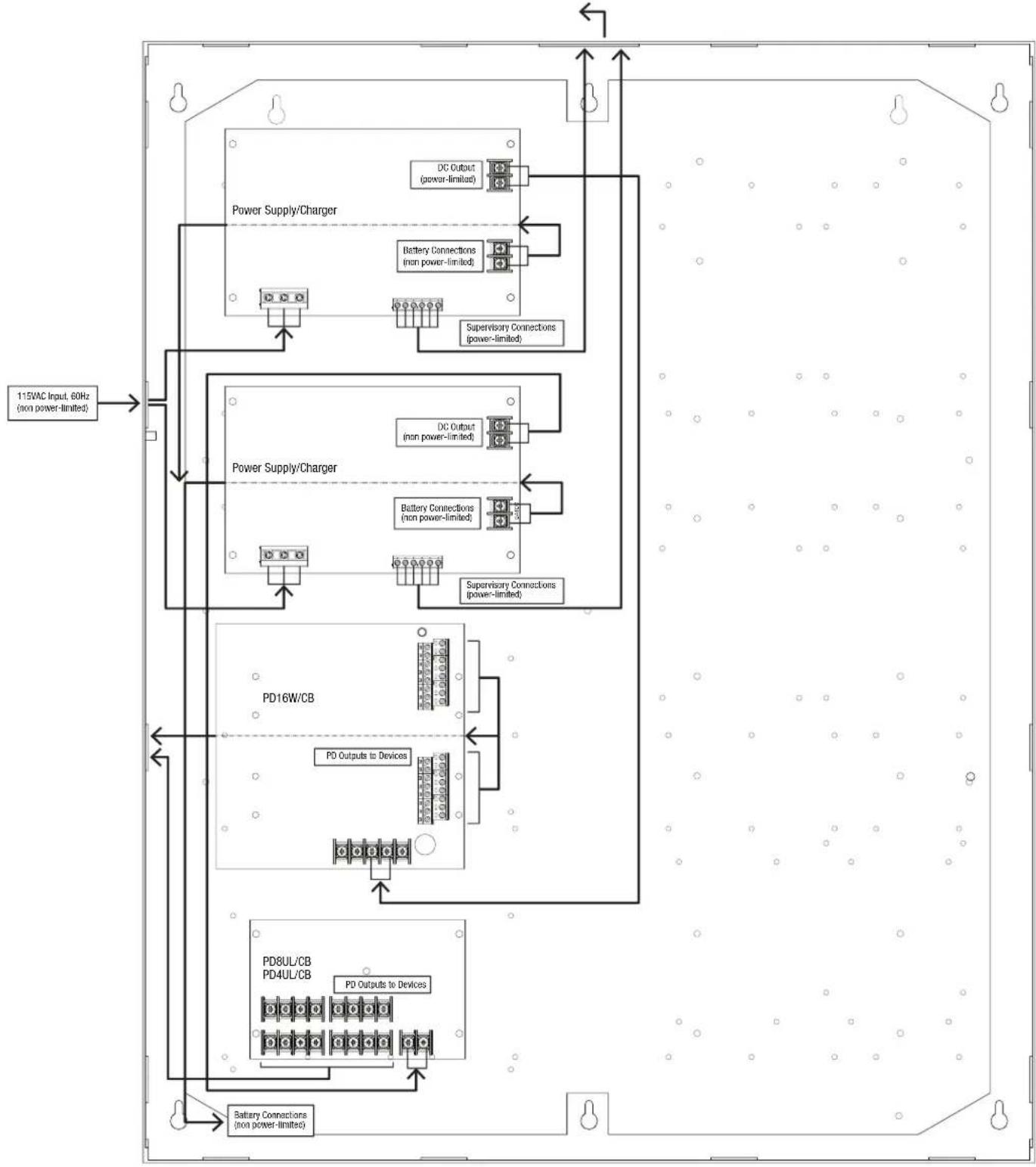
flowchart
graph TD
    A["115VAC Input, 60Hz (non power-limited)"] --> B["Power Supply/Charger"]
    B --> C["DC Output (power-limited)"]
    B --> D["Battery Connections (non power-limited)"]
    B --> E["Supervisory Connections (power-limited)"]
    B --> F["Power Supply/Charger"]
    F --> G["DC Output (non power-limited)"]
    F --> H["Battery Connections (non power-limited)"]
    F --> I["Supervisory Connections (power-limited)"]
    F --> J["PD16W/CB"]
    J --> K["PD Outputs to Devices"]
    J --> L["PD8UL/CB"]
    L --> M["PD4UL/CB"]
    L --> N["PD Outputs to Devices"]
    L --> O["Battery Connections (non power-limited)"]
    style A fill:#f9f,stroke:#333
    style B fill:#ccf,stroke:#333
    style F fill:#cfc,stroke:#333
    style J fill:#fcc,stroke:#333
    style L fill:#cff,stroke:#333
    style K fill:#ffc,stroke:#333
    style M fill:#cfc,stroke:#333
    style N fill:#fcc,stroke:#333
Trove2 MOM5 Configuration:
Fig. 9
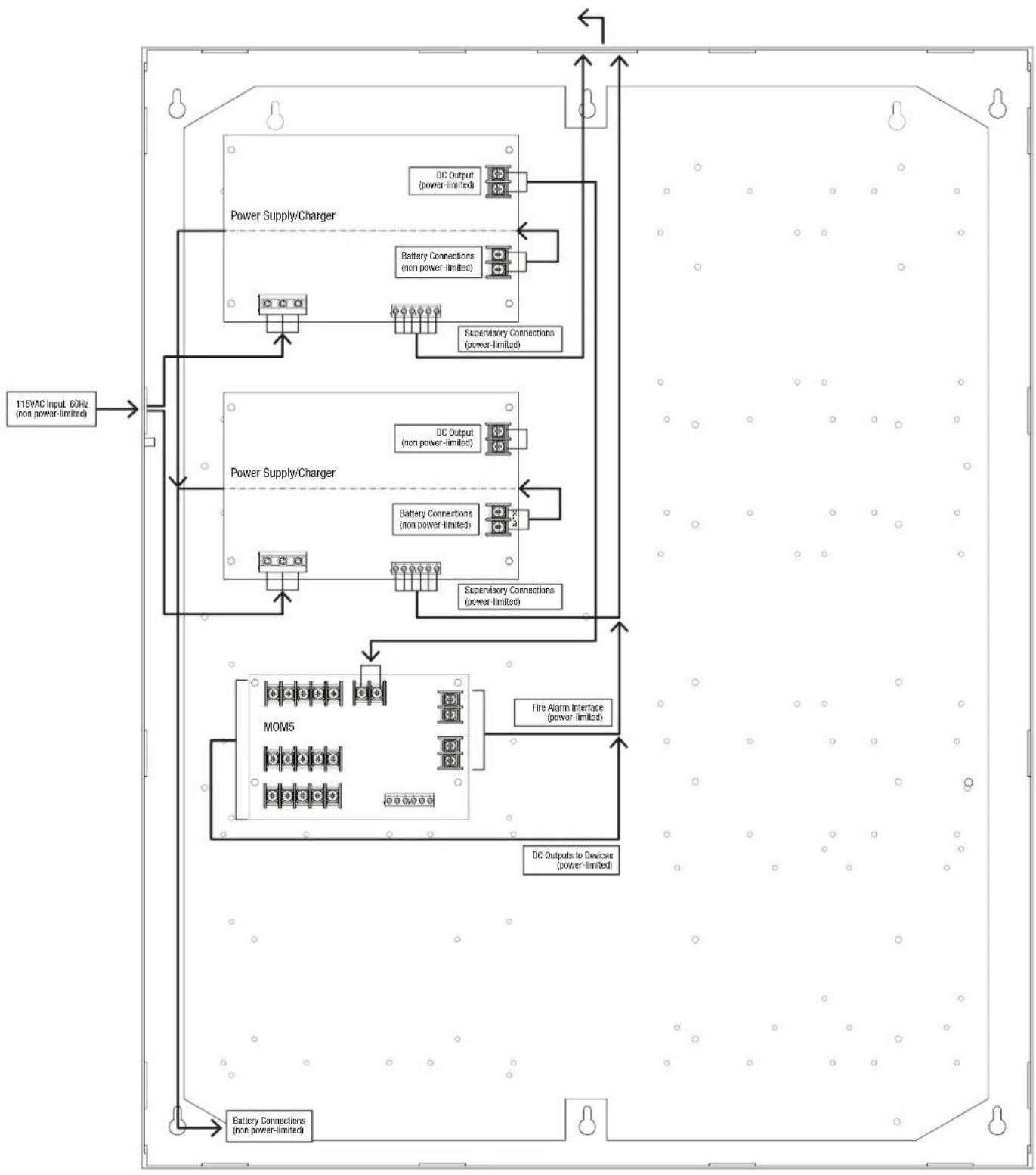
flowchart
graph TD
    A["115VAC Input, 60Hz (non power-limited)"] --> B["Power Supply/Charger"]
    B --> C["DC Output (power-limited)"]
    B --> D["Battery Connections (non power-limited)"]
    B --> E["Supervisory Connections (power-limited)"]
    B --> F["DC Output (non power-limited)"]
    B --> G["Battery Connections (non power-limited)"]
    B --> H["Supervisory Connections (power-limited)"]
    B --> I["MOM5"]
    I --> J["Fire Alarm Interface (power-limited)"]
    I --> K["DC Outputs to Devices (power-limited)"]
    I --> L["Battery Connections (non power-limited)"]
Trove2 ACM Configuration:
Fig. 10
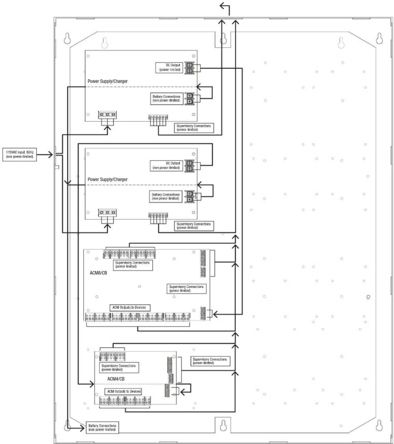
flowchart
graph TD
    A["115VAC Input 60Hz (non power-limited)"] --> B["Power Supply/Charger"]
    B --> C["DC Output (power-limited)"]
    B --> D["Battery Connections (non power-limited)"]
    B --> E["Supervisory Connections (power-limited)"]
    B --> F["Power Supply/Charger"]
    F --> G["DC Output (non power-limited)"]
    F --> H["Battery Connections (non power-limited)"]
    F --> I["Supervisory Connections (power-limited)"]
    F --> J["ACM8/CB"]
    J --> K["Supervisory Connections (power-limited)"]
    J --> L["Supervisory Connections (power-limited)"]
    J --> M["ACM Outputs to Devices"]
    J --> N["ACM4/CB"]
    N --> O["Supervisory Connections (power-limited)"]
    N --> P["Supervisory Connections (power-limited)"]
    N --> Q["ACM Outputs to Devices"]
    N --> R["Battery Connections (non power-limited)"]
TMV2 Sub-Assembly Configuration:
Fig. 11
Trove3 ACM/PD Configuration:
Fig. 12
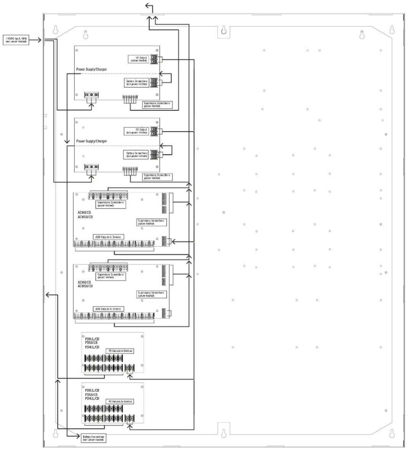
flowchart
graph TD
    A["150DC (input, 6Hz) (net power-limited)"] --> B["Power Supply/Charger"]
    B --> C["DC Generator (power-limited)"]
    B --> D["Collection Connections (net power-limited)"]
    B --> E["Supervisory Connections (power-limited)"]
    B --> F["Power Supply/Charger"]
    F --> G["DC Output (net power-limited)"]
    F --> H["Collection Connections (net power-limited)"]
    F --> I["Supervisory Connections (power-limited)"]
    B --> J["ACM8/C8 ACMSR/CB"]
    J --> K["Supervisory Connections (power-limited)"]
    J --> L["Supervisory Connections (power-limited)"]
    J --> M["ACM Computer to Devices"]
    J --> N["Supervisory Connections (power-limited)"]
    J --> O["ACM8/C8 ACMSR/CB"]
    O --> P["Supervisory Connections (power-limited)"]
    O --> Q["Supervisory Connections (power-limited)"]
    O --> R["ACM Computer to Devices"]
    O --> S["PO Busuate to Devices"]
    O --> T["PO Busuate to Devices"]
    O --> U["PO Busuate to Devices"]
    O --> V["PO Busuate to Devices"]
    O --> W["PO Busuate to Devices"]
    O --> X["PO Busuate to Devices"]
    O --> Y["PO Busuate to Devices"]
    O --> Z["PO Busuate to Devices"]
    O --> AA["PO Busuate to Devices"]
    O --> AB["PO Busuate to Devices"]
    O --> AC["PO Busuate to Devices"]
    O --> AD["PO Busuate to Devices"]
    O --> AE["PO Busuate to Devices"]
    O --> AF["PO Busuate to Devices"]
    O --> AG["PO Busuate to Devices"]
    O --> AH["PO Busuate to Devices"]
    O --> AI["PO Busuate to Devices"]
    O --> AJ["PO Busuate to Devices"]
    O --> AK["PO Busuate to Devices"]
    O --> AL["PO Busuate to Devices"]
    O --> AM["PO Busuate to Devices"]
    O --> AN["PO Busuate to Devices"]
    O --> AO["PO Busuate to Devices"]
    O --> AP["PO Busuate to Devices"]
    O --> AQ["PO Busuate to Devices"]
    O --> AR["PO Busuate to Devices"]
    O --> AS["PO Busuate to Devices"]
    O --> AT["PO Busuate to Devices"]
    O --> AU["PO Busuate to Devices"]
    O --> AV["PO Busuate to Devices"]
    O --> AW["PO Busuate to Devices"]
Altronix®
eFlow Power Supply/Chargers can be Controlled and Monitored while Reporting Power/Diagnostics from Anywhere over the Network...
natural_image
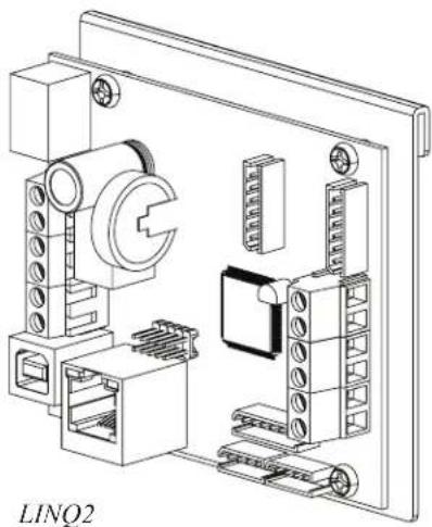
Technical line drawing of an industrial control panel with components and mounting holes (no text or symbols)LINQ™
LINQ2 - Network Communication Module
LINQ2 provides remote IP access to real-time data from cFlow power supply/chargers to help keep systems up and running at optimal levels. It facilitates fast and easy installation and set-up, minimizes system downtime, and eliminates unnecessary service calls, which helps reduce Total Cost of Ownership (TCO) - as well as creating a new source of Recurring Monthly Revenue (RMR).
Features:
- UL Listed in the U.S. and Canada.
- Local or remote control of up to (2) two Altronix eFlow power output(s) via LAN and/or WAN.
- Monitor real time diagnostics: DC output voltage, output current, AC & battery status/service, input trigger state change, output state change and unit temperature.
- Access control and user management: Restrict read/write, Restrict users to specific resources
- Two (2) integral network controlled Form "C" Relays.
- Three (3) programmable input triggers: Control relays and power supplies via external hardware sources.
- Email and Windows Dashboard notifications
- Event log tracks history.
- Secure Socket Layer (SSL).
- Programmable via USB or web browser - includes operating software and 6 ft. USB cable.
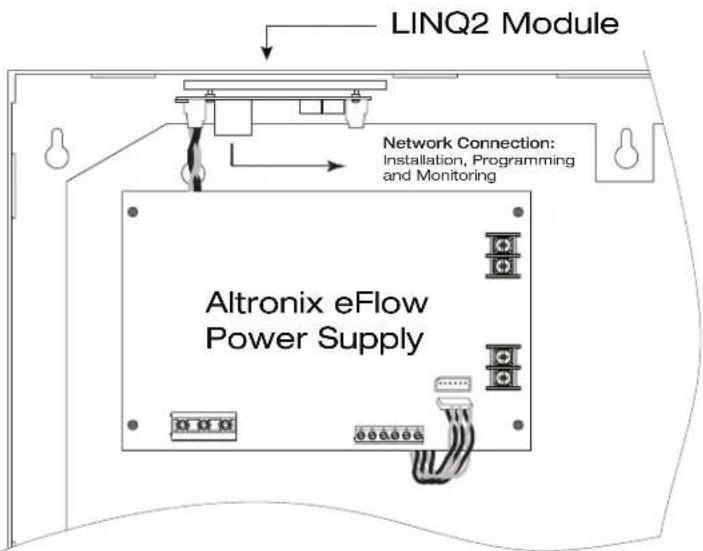
LINQ2 Mounts Inside any Trove Enclosure
Notes:
Notes:
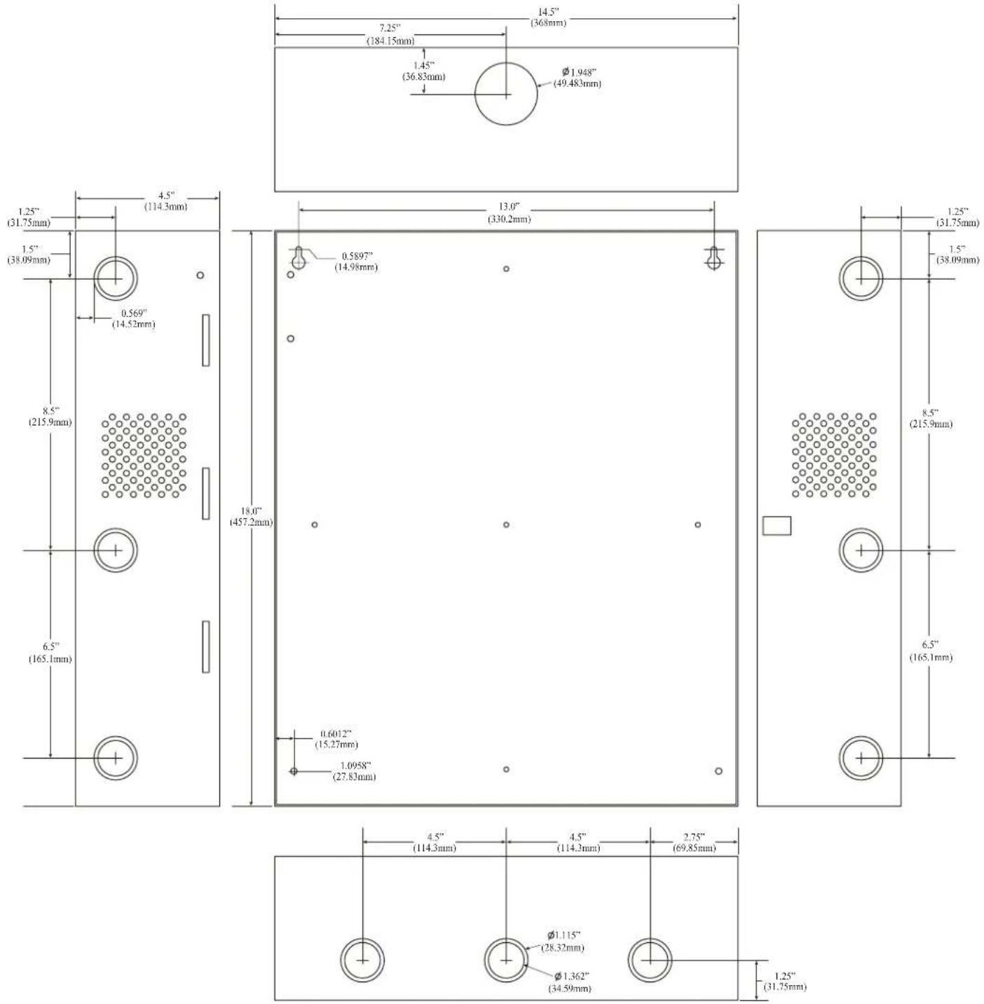
Trove1 Enclosure Dimensions:
18" x 14.5" x 4.625" (457.2mm x 368.3mm x 117.47mm)
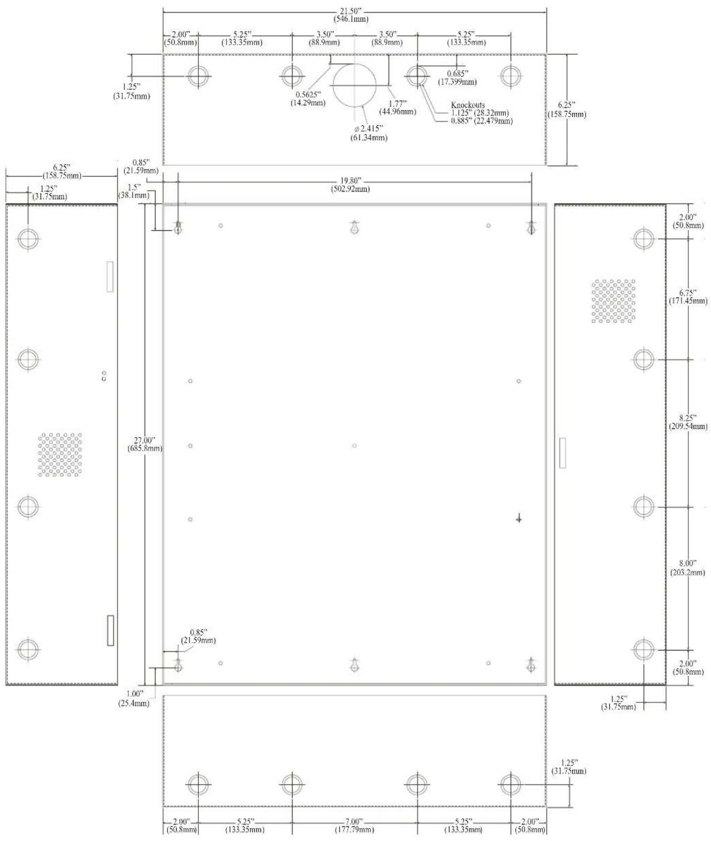
Trove2 Enclosure Dimensions:
27.25" x 21.75" x 6.5" (692.15mm x 552.5mm x 165.1mm)
Trove3 Enclosure Dimensions:
36.12" x 30.125" x 7.06" (917.5mm x 768.1mm x 179.3mm)
Altronix is not responsible for any typographical errors. Product specifications are subject to change without notice.
140 58th Street, Brooklyn New York 11220 USA | phone: 718-567-8181 | fax: 718-567-9056
website: www.altronix.com | e-mail: info@altronix.com | Made in USA.
II Trove Series - Rev. 101817 J14S

- Access & Power Integration
- Installation Guide
- Overview:
- Door Backplanes for System Expansion:
- Specifications:
- Agency Listings:
- Environmental:
- Battery Backup:
- Additional Features:
- Installation Instructions:
- For eFlow Power Supply/Chargers (steps 7-10):
- Power Supply Board Output Voltage Settings:
- Maintenance:
- Altronix®
- eFlow Power Supply/Chargers can be Controlled and Monitored while Reporting Power/Diagnostics from Anywhere over the Network...
- LINQ™
- LINQ2 - Network Communication Module
- Features:
- Notes:
Brand : Altronix
Model : Trove3SH3
Category : Access Control System