
T3MK75F16 - Access Control System Altronix - Free user manual and instructions
Find the device manual for free T3MK75F16 Altronix in PDF.


| Product Type | Access Control Power Supply/Controller |
| Brand | Altronix |
| Model | T3MK75F16 |
| Input Voltage | 115VAC, 60Hz |
| Input Current | 1.5A |
| Output Voltage | 24VDC @ 6A or 12VDC @ 4A |
| Number of Fused Outputs | 16 |
| Battery Backup | Up to 7Ah, 12VDC or 24VDC |
| Enclosure Dimensions | 13.5" x 13" x 3.5" (343 x 330 x 89 mm) |
| Weight | 8.5 lbs (3.9 kg) |
| Operating Temperature | 0°C to 40°C (32°F to 104°F) |
| Primary Functions | Power distribution, fuse protection, battery charging, AC fail detection |
| Safety Certifications | UL listed, surge protection, fuse protected outputs |
| Maintenance & Cleaning | Disconnect power, clean with dry cloth; do not use liquids |
| Spare Parts & Repairability | Replaceable fuses (Pico fuse 1A), battery; no user-serviceable internal parts |
| General Information | Indoor use only; mount in a secure location; for use with access control systems |
Frequently Asked Questions - T3MK75F16 Altronix
User questions about T3MK75F16 Altronix
0 question about this device. Answer the ones you know or ask your own.
Ask a new question about this device
Download the instructions for your Access Control System in PDF format for free! Find your manual T3MK75F16 - Altronix and take your electronic device back in hand. On this page are published all the documents necessary for the use of your device. T3MK75F16 by Altronix.
USER MANUAL T3MK75F16 Altronix
Access & Power Integration
T3MK75F16
16 Door Kit with Fused Outputs
Fully assembled kit includes:
- Trove3 enclosure with TM3 Altronix/Mercury backplane
- One (1) eFlow104NB - Power Supply/Charger
- One (1) eFlow102NB - Power Supply/Charger
- Two (2) ACM8 - Fuse Protected Access Power Controllers
- One (1) PD8UL - Fuse Protected Power Distribution Module
- One (1) Rocker Switch Bracket with Two (2) Rocker Switches (Not evaluated by UL)
T3MK77F16
16 Door Kit with Fused Outputs
Fully assembled kit includes:
- Trove3 enclosure with TM3 Altronix/Mercury backplane
- Two (2) eFlow104NB - Power Supply/Chargers
- Two (2) ACM8 - Fuse Protected Access Power Controllers
- Two (2) PD8UL - Fuse Protected Power Distribution Modules
- One (1) Rocker Switch Bracket with Two (2) Rocker Switches (Not evaluated by UL)
T3MK75F16D
16 Door Kit with PTC Outputs
Fully assembled kit includes:
- Trove3 enclosure with TM3 Altronix/Mercury backplane
- One (1) eFlow104NB - Power Supply/Charger
- One (1) eFlow102NB - Power Supply/Charger
- Two (2) ACM8CB - PTC Protected Access Power Controllers
- One (1) PD8ULCB - PTC Protected Power Distribution Module
- One (1) Rocker Switch Bracket with Two (2) Rocker Switches (Not evaluated by UL)
T3MK77F16D
16 Door Kit with PTC Outputs
Fully assembled kit includes:
- Trove3 enclosure with TM3 Altronix/Mercury backplane
- Two (2) eFlow104NB - Power Supply/Chargers
- Two (2) ACM8CB - PTC Protected Access Power Controllers
- Two (2) PD8ULCB - PTC Protected Power Distribution Modules
- One (1) Rocker Switch Bracket with Two (2) Rocker Switches (Not evaluated by UL)
All components of these Trove kits are UL Listed sub-assemblies.
Please refer to the included corresponding Sub-Assembly Installation Guides for further information.
Installation Guide

All registered trademarks are property of their respective owners. More than just power. ^TM
Rev. T3MK071818
Installing Company: ____ Service Rep. Name: ____
Address: ____ Phone #: ____
Overview:
Altronix Trove Mercury kits are pre-assembled and consist of Trove3M3 enclosure/backplane with factory installed Altronix power supply/charger(s) and sub-assemblies. These kits also accommodate various combinations of Mercury boards for up to sixteen (16) doors in a single enclosure.
Configuration Chart:
| Altronix Model Number | 120VAC 60Hz Input Current (A) | Power Supply Board Input Fuse Rating | Power Supply Board Battery Fuse Rating | Nominal DC Output Voltage | Maximum Supply Current for Main and Aux. Outputs on Power Supply board and ACM8(CB) Access Power Controller's outputs | Fail-Safe/Fail-Secure or Dry Form "C" Outputs | Current Per ACM8(CB) Output (A) | ACM8(CB) Board Input Fuse Rating | ACM8 Board Output Fuse Rating | ACM8CB Board Output PTC Rating | PD8UL Board Output Fuse Rating | PD8ULCB Board Output Fuse Rating | |||
| Power Supply 1 | Power Supply 2 | ||||||||||||||
| [DC] | [Aux] | [D C] | [Aux] | ||||||||||||
| Output Range (VDC) | Output Range (VDC) | Output Range (VDC) | Output Range (VDC) | ||||||||||||
| T3MK75F16 | 8 | 6.3A/250V 5A/250V | 15A/32V | 20.17-26.4 | 20.28-26.4 | 9.7-13.2 | 10.03-13.2 | 12VDC @ 9.3A 24VDC @ 9.2A | 16 2.5 | 10A/250V | 2.5A/250V | - | 3.5A/250V | - | |
| T3MK75F16D | 8 | 6.3A/250V 5A/250V | 15A/32V | 20.17-26.4 | 20.28-26.4 | 9.7-13.2 | 10.03-13.2 | 12VDC @ 9.3A 24VDC @ 9.2A | 16 2.5 | 10A/250V | -2A | -2.5A | |||
| T3MK77F16 | 9 | 6.3A/250V | 15A/32V | 20.17-26.4 | 20.28-26.4 | 20.17-26.4 | 20.28-26.4 | 24VDC @ 9.2A 16 2.5 | 10A/250V | 2.5A/250V | - | 3.5A/250V | - | ||
| T3MK77F16D | 9 | 6.3A/250V | 15A/32V | 20.17-26.4 | 20.28-26.4 | 20.17-26.4 | 20.28-26.4 | 24VDC @ 9.2A 16 2.5 | 10A/250V | -2A | -2.5A | ||||
Hardware and Accessories:
- Two (2) tamper switches (Altronix Model TS112 or equivalent).
- Cam lock.
- Battery leads.
Mechanical:
• 16 Gauge enclosure with ample knockouts for convenient access.
- Enclosure Dimensions (H x W x D): 36.12" x 30.125" x 7.06" (917.5mm x 768.1mm x 179.3mm).
Installation Instructions:
Wiring methods shall be in accordance with the National Electrical Code/NFPA 70/ANSI, and with all local codes and authorities having jurisdiction. Product is intended for indoor use only.
- Remove backplane from enclosure. Do not discard hardware.
- Mark and predrill holes in the wall to line up with the top three keyholes in the enclosure. Install three upper fasteners and screws in the wall with the screw heads protruding. Place the enclosure's upper keyholes over the three upper screws, level and secure. Mark the position of the lower three holes. Remove the enclosure. Drill the lower holes and install the three fasteners. Place the enclosure's upper keyholes over the three upper screws.
Install the three lower screws and make sure to tighten all screws.
- Mount included UL Listed tamper switches (Altronix Model TS112 or equivalent) in desired location, opposite hinge. Slide the tamper switch bracket onto the edge of the enclosure approximately 2"
from the right side (Fig. 1, pg. 2). Connect tamper switch wiring to the Access Control Panel input or the appropriate UL Listed reporting device.
To activate alarm signal open the door of the enclosure.
- Mount Mercury boards to backplane, refer to pg. 3, 4.
- Refer to the eFlow Power Supply/Charger Installation Guide for eFlow104NB, eFlow102NB and corresponding Sub-Assembly Installation Guides for PD8UL(CB) and ACM8(CB) for further installation instructions.
- Position Mercury access controller module over corresponding standoffs and depress onto snap on standoffs (Fig. 2-3, pg. 3-4).
- Mount backplane to enclosure with hardware.

T3MK75F16 and T3MK75F16D: Configuration of Mercury Boards:
- Fasten snap on standoffs onto metal pems configuration (A) (B) of backplane depending on the access controller (Fig. 2, pg. 3).
- Position access controller module over corresponding standoffs and depress onto snap on standoffs (Fig. 2a, pg. 3).
- Mount backplane to enclosure with hardware.
Access Controller Position Chart for the Following Models:
| Mercury Access Controller Pem Mounting | |
| EP1502, MR52, MR16IN, MR16OUT | A |
| EP2500, MUX8 | B |
| EP1501, MR51e | C |
| MR52 | D |
Fig. 2
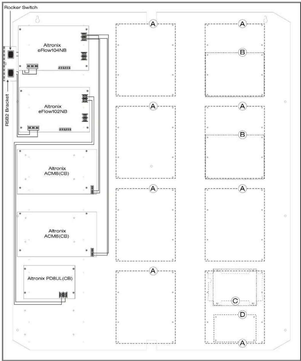
flowchart
graph TD
    A["Rocker Switch"] --> B["Altronix eFlow104NB"]
    A --> C["Altronix eFlow102NB"]
    A --> D["Altronix ACM8(CB)"]
    A --> E["Altronix ACM8(CB)"]
    A --> F["Altronix PD8UL(CB)"]
    B --> G["A"]
    C --> H["B"]
    D --> I["A"]
    E --> J["B"]
    F --> K["A"]
    G --> L["C"]
    H --> M["D"]
    I --> N["A"]
    J --> O["B"]
    K --> P["A"]

T3MK77F16 and T3MK77F16D: Configuration of Mercury Boards on TM3:
- Fasten snap on standoffs onto metal pems configuration (A) (B) of backplane depending on the access controller (Fig. 3, pg. 4).
- Position access controller module over corresponding standoffs and depress onto snap on standoffs (Fig. 3a, pg. 4).
- Mount backplane to enclosure with hardware.
Access Controller Position Chart for the Following Models:
| Mercury Access Controller Pem Mounting | |
| EP1502, MR52, MR16IN, MR16OUT | A |
| EP2500, MUX8 | B |
| EP1501, MR51e | C |
| MR52 | D |
Fig. 3

flowchart
graph TD
    A["Rocker Switch"] --> B["Altronix eFlow104NB"]
    B --> C["Altronix eFlow104NB"]
    C --> D["Altronix ACM8(CB)"]
    D --> E["Altronix ACM8(CB)"]
    E --> F["Altronix PD8UL(CB)"]
    F --> G["Altronix PD8UL(CB)"]
    G --> H["A"]
    H --> I["A"]
    H --> J["B"]
    H --> K["A"]
    K --> L["A"]
    K --> M["B"]
    K --> N["A"]
    N --> O["A"]
    N --> P["A"]
    N --> Q["C"]
    N --> R["D"]
    N --> S["A"]

Notes:

eFlow Power Supply/Chargers can be Controlled and Monitored while Reporting Power/Diagnostics from Anywhere over the Network...

natural_image
Technical line drawing of an industrial control panel with components and mounting holes (no text or symbols)
LINQ2 - Network Communication Module
LINQ2 provides remote IP access to real-time data from eFlow power supply/chargers to help keep systems up and running at optimal levels. It facilitates fast and easy installation and set-up, minimizes system downtime, and eliminates unnecessary service calls, which helps reduce Total Cost of Ownership (TCO) - as well as creating a new source of Recurring Monthly Revenue (RMR).
Features:
- UL Listed in the U.S. and Canada.
- Local or remote control of up to (2) two Altronix cFlow power output(s) via LAN and/or WAN.
- Monitor real time diagnostics: DC output voltage, output current, AC & battery status/service, input trigger state change, output state change and unit temperature.
- Access control and user management: Restrict read/write, Restrict users to specific resources
- Two (2) integral network controlled Form "C" Relays.
- Three (3) programmable input triggers: Control relays and power supplies via external hardware sources.
- Email and Windows Dashboard notifications
- Event log tracks history.
- Secure Socket Layer (SSL).
- Programmable via USB or web browser - includes operating software and 6 ft. USB cable.
LINQ2 Mounts Inside any Trove Enclosure

TM3 Dimensions
34" x 28" x 0.3125" (863.6mm x 711.2mm x 7.9mm)

Trove3 Enclosure Dimensions (H x W x D approximate):
36.12" x 30.125" x 7.06" (917.5mm x 768.1mm x 179.3mm)


- Access & Power Integration
- T3MK75F16
- Door Kit with Fused Outputs
- Fully assembled kit includes:
- T3MK77F16
- T3MK75F16D
- Door Kit with PTC Outputs
- T3MK77F16D
- Installation Guide
- Overview:
- Hardware and Accessories:
- Mechanical:
- Installation Instructions:
- T3MK75F16 and T3MK75F16D: Configuration of Mercury Boards:
- T3MK77F16 and T3MK77F16D: Configuration of Mercury Boards on TM3:
- eFlow Power Supply/Chargers can be Controlled and Monitored while Reporting Power/Diagnostics from Anywhere over the Network...
- LINQ2 - Network Communication Module
- Features:
Brand : Altronix
Model : T3MK75F16
Category : Access Control System