IBR1150 - Router Cradlepoint - Free user manual and instructions
Find the device manual for free IBR1150 Cradlepoint in PDF.

User questions about IBR1150 Cradlepoint
0 question about this device. Answer the ones you know or ask your own.
Ask a new question about this device
Download the instructions for your Router in PDF format for free! Find your manual IBR1150 - Cradlepoint and take your electronic device back in hand. On this page are published all the documents necessary for the use of your device. IBR1150 by Cradlepoint.
USER MANUAL IBR1150 Cradlepoint
CradlePoint COR IBR1100/IBR1150 – Manual
natural_image
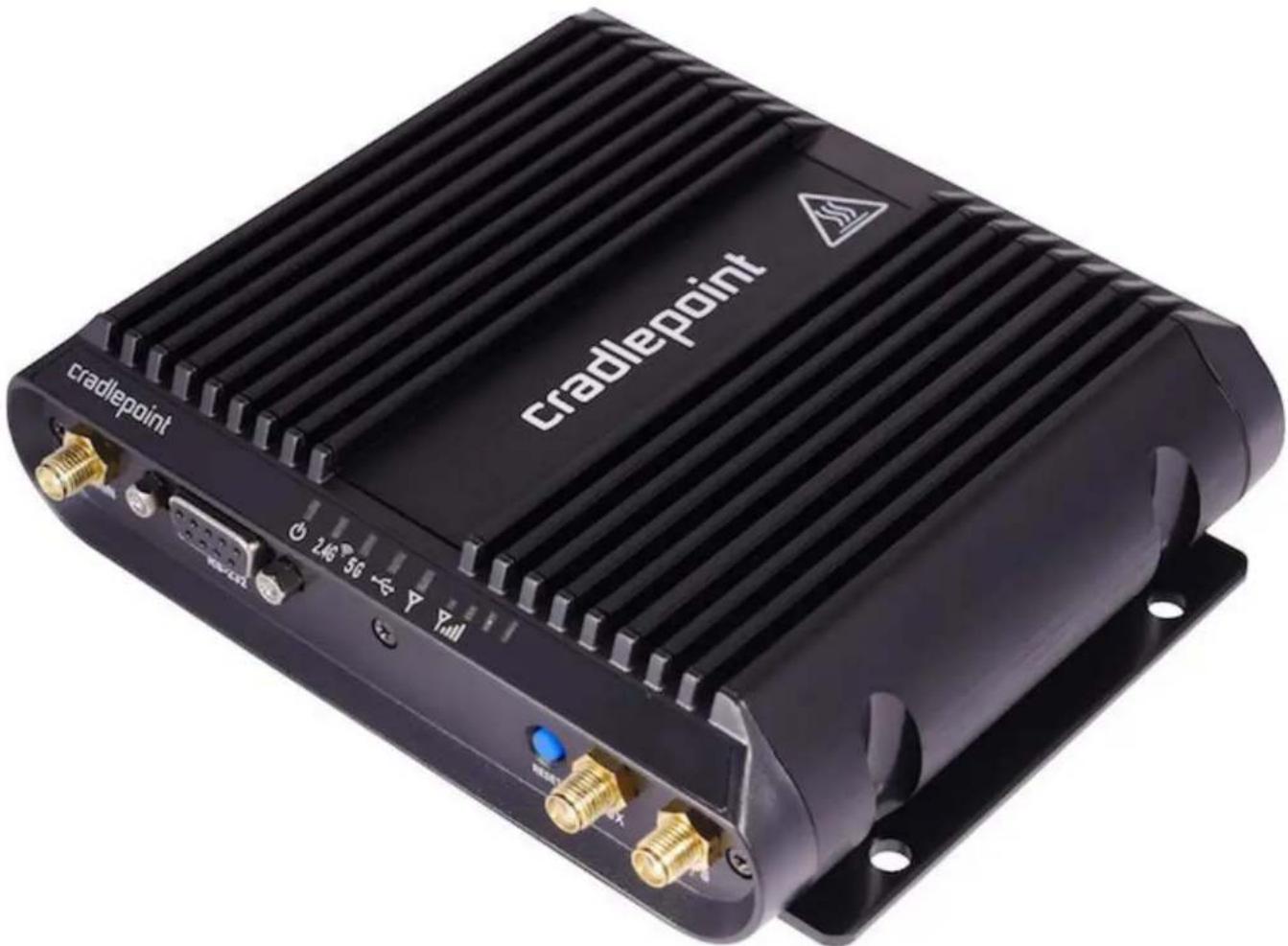
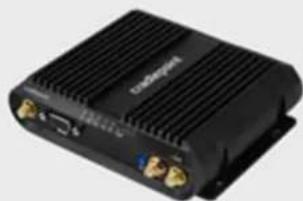
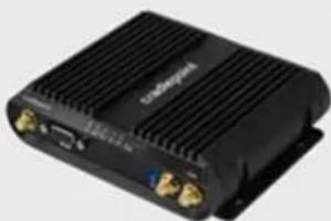
Black Cradlepoint electronic device with ventilation slots and ports (no readable text beyond branding)Highly Available, Cloud-Managed Networking for Extreme Conditions
The CradlePoint COR IBR1100 Series is a compact, ruggedized 3G/4G/LTE networking solution designed for mission critical connectivity in the most challenging environments.
Ideal for in-vehicle networks including police cars, ambulances, and mass transit, this cloud-managed solution provides organizations the ability to scale deployments quickly and manage their vehicle networks easily in real-time.
With an extensive list of safety and hardening certifications, the COR IBR1100 is engineered to protect against extreme temperatures, humidity, shocks, vibrations, dust, water splash, reverse polarity and transient voltage.
Key Features
• Cloud-managed for zero-touch deployment and intelligent management
• Internal 3G/4G modem with secured SIM card access and dual SIM slots
• LTE support for all major U.S. carriers and Europe/international operators (failover to HSPA+ or EVDO)
• Software-defined radio supports multiple carriers (Gobi)
- WiFi (IBR1100) and non-WiFi versions (IBR1150) available: IBR1100 includes dual-band dual-concurrent 2.4/5 GHz 802.11 a/b/g/n/ac WiFi; 2 x 2 MIMO with two external dual-band antenna connectors
- Ignition sensing
• Ruggedized: protects against vibration, shock, dust, splash, & humidity
• Built-in transient and reverse polarity voltage protection; 9–36 DC voltage input range
• Integrated temperature sensor
• Three 10/100 Ethernet ports (LAN/WAN configurable)
• Antenna connectors for external cellular modem (two) and active GPS (one)
• RS-232 serial port
Introduction
• Package Contents
• System Requirements
- Specifications
Hardware
• LEDs
Quick Start
- Basic Setup
• Accessing the Administration Pages - First Time Setup Wizard
• Using Enterprise Cloud Manager
Administration Pages
The COR IBR1100/IBR1150 administration pages include the following five labs:

See Navigating the Administration Pages for helpful information about how to use the device's GUI-based management interface.
NOTE: The manual content for the following administration pages sections is generic across multiple devices. Therefore, some details may not apply to the COR IBR1100 or COR IBR1150 because they are specific to another device. For example, CP Secure Threat Management is only available for the AER 2100. Also, the configuration pages within Enterprise Cloud Manager (ECM) are very similar to the local router administration pages, but some items are missing because they are not relevant in the ECM environment. For example, the entire Status tab is absent in ECM because status information is presented in other ways (Dashboard, Devices list, etc.).
Getting Started
• Enterprise Cloud Manager Registration
- First Time Setup
• IP Passthrough Setup
Status
- Client List
- Dashboard
GPS
• GRE Tunnels - Hotspot Clients
- Internet Connections
- Routing
• Statistics - System Logs
• VPN Tunnels
• WiPipe QoS
Network Settings
- Content Filtering
- DHCP Server
DNS - Firewall
• MAC Filter / Logging - Routing
- Routing Protocols
- WiFi / Local Networks
• WiPipe QoS
Internet
- Connection Manager
- Client Data Usage
Data Usage
• GRE Tunnels
• L2TP Tunnels
• Network Mobility (NEMO)
• NHRP Interfaces
• OpenVPN Tunnels (coming Q4)
• VPN Tunnels
• WAN Affinity / Load Balancing
• WiFi as WAN / Bridge
System Settings
- Administration
• Certificate Management
• Device Alerts - GPIO Connector
• Enterprise Cloud Manager
• Feature Licenses - Hotspot Services
- Serial Redirector
SNMP Configuration - System Control
System Software
Introduction
• Package Contents
• System Requirements
- Specifications
- Hardware
• LEDs
Package Contents
• Ruggedized router with integrated business class 3G/4G modem; includes integrated mounting plate
• Two meter locking power and GPIO cable (direct wire)
• Quick Start Guide with warranty information
NOTE: Due to the diverse needs of customers, the COR IBR1100/IBR1150 package does not include a power adapter or antennas. See the Accessories section below for several power and antenna options.
System Requirements
- At least one Internet source: a CradlePoint integrated 3G/4G modem with an active data plan, an Ethernet-based modem, or WIFI as WAN
- Windows 2000/XP/7/8, Mac OS X, or Linux computer (with WiFi adapter – 802.11n recommended – for WiFi functionality).
- Internet Explorer v6.0 or higher, Firefox v2.0 or higher, Salari v1.0 or higher.
Specifications
WAN
• Integrated 4G LTE modem (with 3G fallover)
- Three LAN/WAN switchable 10/100 Ethernet ports – one default WAN (cable/DSL/T1/satellite/Metro Ethernet)
- WiFi as WAN, Metro WIFI; 2x2 MIMO "N" 2.4 GHz or 5 GHz; 802.11 a/b/g/n/ac (IBR1100 only)
LAN
• Dual-band dual-concurrent WiFi; 802.11 a/b/g/n/ac (IBR1100 only)
- Three LAN/WAN switchable 10/100 Ethernet ports – two default LAN
- Serial console support for out-of-band management of a connected device
PORTS
Power
- 2-wire GPIO
USB 2.0
• 3 Ethernet LAN/WAN
• 2 cellular antenna connectors (SMA)
• 1 active GPS antenna connector (SMA)
• 2 WiFi antenna connectors (R-SMA)
- Serial DE-9 (commonly called "DB-9") connector – RS-232 (out-of-band management of an external device requires a null modem adapter/cable)
TEMPERATURE
- -30°C to 70°C (-22°F to +158°F) operating
- -40 °C to 85 °C (-40 °F to +185 °F) storage
- Includes temperature sensor with options for alerts and automatic shutoff
HUMIDITY (non-condensing)
- 5% to 95% operating
- 5% to 95% storage
POWER
- DC input steady state voltage range: 9–36 VDC (requires inline fuse for vehicle installations)
- For 9–24 VDC installations, use a 3 A fuse
- For > 24 VDC installations, use a 2.5 A fuse
• Reverse polarity and transient voltage protection per ISO 7637-2
- Ignition sensing (automatic ON and time-delay OFF)
• Power consumption:
- idle: typical=400mA@12VDC (4.8W); worst case=800mA@12VDC (9.6W)
- Tx/Rx: typical=650mA@12VDC (7.8W); worst case=1300mA@12VDC (15.6W)
- 12VDC 2A adapter recommended
SIZE - 5.3 in x 4.4 in x 1.4 in (134 mm x 112 mm x 35 mm)
WEIGHT - 16.1 oz (457 g)
CERTIFICATIONS
- FCC, CE, IC
• WiFi Alliance (IBR1100 only) – 802.11a/b/g/n certified, 802.11ac supported
• Safety: UL/CUL, CB Scheme, EN60950-1
• Hazardous Locations: Class I, Div. 2 (pending)
• Shock/Vibration/Humidity: compliant with MIL STD 810G and SAEJ1455 - Ingress Protection: compliant with IP64 (includes protection from dust and splashing water)
• Materials: WEEE, RoHS, RoHS-2, California Prop 65
• Vehicle: E-Mark, compliant with ISO 7637-2
• Telecom: PTCRB/CTIA, GCF-CC
GPS
• GPS Protocols: TAIP and NMEA 0183 V3.0
- Accuracy:
- < 2m: 50%
- <5m: 90%
• Acquisition:
- Hot start: 1 second
- Warm start: 29 seconds
- Cold start: 32 seconds
- Sensitivity
- Tracking: -161 dBm (tracking sensitivity is the lowest GNSS signal level for which the device can still detect an in-view satellite 50% of the time when in sequential tracking mode)
- Acquisition (standalone): -145 dBm (acquisition sensitivity is the lowest GNSS signal level for which the device can still detect an in-view satellite 50% of the time)
- Operational limits: altitude < 6000 m or velocity < 100 m/s (either limit may be exceeded, but not both)
Feature Details
- WAN Security – NAT, SPI, ALG, inbound filtering of IP addresses, port blocking, service filtering (FTP, SMTP, HTTP, RPL, SNMP, DNS, ICMP, NNTP, POP3, SSH), protocol filtering, WAN ping (allow/ignore)
- Redundancy and Load Balancing – Failover/failback with 4G, 3G, Ethernet with rule selection, advanced load balancing options (round robin, spillover, data usage, rate), WAN failure detection, VRRP
- Intelligent Routing – UPnP, DMZ, virtual server/port forwarding, routing rules, NAT-less routing, wired or wireless WAN-to-LAN IP passthrough, route management, per-interface routing, content filtering, IP filtering, website filtering, per-client Web filtering, local DHCP server, DHCP client, DHCP relay, DNS, DNS proxy; ALGs: PPTP, SIP, TFTP, FTP, IRC; MAC address filtering, Dynamic DNS, LAN/WAN affinity, VLAN 802.1Q (coming Q4), STP, enterprise routing protocols: BGP/OSPF/RIP, multicast proxy support, IP setting overrides, IPv6 support
- Management – Enterprise Cloud Manager: cloud-enabled management and application platform (subscription-based); web-based GUI (local management), optional RADIUS or TACACS+ username/password; remote WAN web-based management w/ access control (HTTP, HTTPS); SNMP v1, v2c, & v3; CLI over SSH, SSH to serial, SSH to telnet; API; one-button firmware upgrade; modem configuration, update, and management; modem data usage w/ alerts, per-client data usage;
custom AT scripting to modems
- Performance & Health Monitoring – Advanced QoS with traffic shaping, with DSCP/DiffServe QoS, Modem Health Management (MHM) improves connectivity of modem, SSID-based priority, WAN port speed control, several levels of basic and advanced logging for troubleshooting
- VPN (IPsec) – Tunnel, NAT-T, and transport modes; connect to CradlePoint, Cisco/Linksys, CheckPoint, Watchguard, Juniper, SonicWall, Adtran and others; certificate support; Hash (MD5, SHA128, SHA256, SHA384, SHA512), Cipher (AES, 3DES, DES); support for 5 concurrent connections, GRE tunneling, L2TP support, multiple networks supported in a single tunnel, site-to-site dynamic VPN with NHRP
- GPS – Active GPS antenna port; GUI mapping; multiple server reporting (coming Q4) with LAN and WAN options; TAIP and NMEA; custom intervals based on time and/or velocity (coming Q4)
Services, Support, and Warranty
- CradleCare Support Agreement available with technical support, software upgrades, and advanced hardware exchange – 1, 3, and 5 year options
- One-year limited hardware warranty available in the US and Canada; two-year limited hardware warranty for integrated EU products when purchased from an authorized EU distributor — extend warranty to 2, 3, or 5 years
• CradleCare Site Survey and Installation services offered for rapid deployment
Accessories
Power
Wall options
- COR IBR1100/IBR1150 extended temperature (-30 °C to 70 °C) 12VDC 2A locking power adapter – requires separate line cord (Part # 170648-000)
• Line cord for North America (Part # 170623-001)
• Line cord for EU (Part # 170623-002)
• Line cord for UK (Part # 170623-003)
• COR 12VDC 2A locking power adapter with 0 °C to 40 °C temperature range – includes US, EU, and UK plugs (Part # 170584-002)
NOTE: CradlePoint primarily recommends the extended temperature adapter because it covers the COR IBR1100/IBR1150 full temperature range of -30 ^ to 70 ^ . Cost-sensitive customers that intend to use the IBR1100/IBR1150 in temperature-controlled office environments can order the 170584-002 adapter, but it limits the operating temperature range to 0 ^ to 40 ^ .
Vehicle options
• Vehicle locking power adapter for COR (Part # 170635-000)
- Two meter locking power and GPIO cable (direct wire) for replacement – included by default (Part # 170585-000)
Antennas – 3G/4G Modem, WiFi, & GPS
• Universal 3G/4G multi-band cellular modem antenna – 2dBi/3dBi (Part # 170649-000)
• 2.4 GHz and 5 GHz dual-band dual-concurrent WiFi antenna (Part # 170628-000)
- 5-in-1 – 3G/4G modem, GPS-GLONASS, and WiFi – screw-mount antenna with 3m cables (Part # 170654-000)
- 3-in-1 – 3G/4G modem and GPS-GLONASS – screw-mount antenna with 3m cables (Part # 170653-000)
• GPS-GLONASS screw-mount antenna with 3m cable (Part # 170651-000)
• GPS-GLONASS magnetic-mount antenna with 3m cable (Part # 170652-000)
• Directional Patch antennas for external (outside) mounting (Part # 170587-000)
• Directional Yagi (Log-Periodic) antennas for external (outside) mounting (Part # 170588-000)
- Omni-directional antennas for external (outside) mounting (Part # 170586-000)
• 12" Mag-mount antenna (Part # 170605-000)
• 4" Mini mag-mount antenna (Part # 170606-000)
See the CradlePoint antenna accessories page for more information about antennas. Also see the Antenna Ordering and Installation Guide, available as a PDF in the Resources section of antenna and router product pages.
Business-Grade Modem Specifications
COR IBR1100/IBR1150 models include an integrated 4G LTE modem – specific model names include a specific modem (e.g., the COR IBR1100LPE-VZ includes a Verizon LTE modem).
Please note that LPE models are flexible and support bands for multiple cellular providers; however, only the frequency bands in bold below are supported by the listed provider.
COR IBR1100LPE-VZ, COR IBR1150LPE-VZ - 4G LTE/HSPA+/EVDO for Verizon
• Technology: LTE, HSPA+, EVDO Rev A
• Downlink Rates: LTE 100 Mbps, HSPA+ 21.1 Mbps, EVDO 3.1 Mbps (theoretical)
• Uplink Rates: LTE 50 Mbps, HSPA+ 5.76 Mbps, EVDO 1.8 Mbps (theoretical)
• Frequency Bands:
- LTE Band 2 (1900 MHz), Band 4 – AWS (1700/2100 MHz), Band 5 (850 MHz), Band 13 (700 MHz), Band 17 (700 MHz), Band 25 (1900 MHz)
- HSPA+/UMTS (850/900/1900/2100 MHz, AWS)
- GSM/GPRS/EDGE (850/900/1800/1900 MHz)
• CDMA EVDO Rev A/1xRTT (800/1900 MHz)
• Power: LTE 23 dBm +/- 1, HSPA+ 23 dBm +/- 1, EVDO 24 dBm +0.5/-1 (typical conducted)
• Antennas: two SMA male (plug), finger tighten only (maximum torque spec is 7 kgf-cm)
• GPS: active GPS support
• Industry Standards & Certs: FCC, Verizon
COR IBR1100LPE-AT, COR IBR1150LPE-AT - 4G LTE/HSPA+/EVDO for AT&T
• Technology: LTE, HSPA+, EVDO Rev A
• Downlink Rates: LTE 100 Mbps, HSPA+ 21.1 Mbps, EVDO 3.1 Mbps (theoretical)
• Uplink Rates: LTE 50 Mbps, HSPA+ 5.76 Mbps, EVDO 1.8 Mbps (theoretical)
• Frequency Bands:
- LTE Band 2 (1900 MHz), Band 4 – AWS (1700/2100 MHz), Band 5 (850 MHz), Band 13 (700 MHz), Band 17 (700 MHz), Band 25 (1900 MHz)
• HSPA+/UMTS (850/900/1900/2100 MHz, AWS) - GSM/GPRS/EDGE (850/900/1800/1900 MHz)
- CDMA EVDO Rev A/1xRTT (800/1900 MHz)
• Power: LTE 23 dBm +/- 1, HSPA+ 23 dBm +/- 1, EVDO 24 dBm +0.5/-1 (typical conducted)
- Antennas: two SMA male (plug), finger tighten only (maximum torque spec is 7 kgf-cm)
• GPS: active GPS support
• Industry Standards & Certs: PTCRB, FCC, IC, AT&T
COR IBR1100LPE-SP, COR IBR1150LPE-SP - 4G LTE/HSPA+/EVDO for Sprint
• Technology: LTE, HSPA+, EVD0 Rev A
• Downlink Rates: LTE 100 Mbps, HSPA+ 21.1 Mbps, EVDO 3.1 Mbps (theoretical)
• Uplink Rates: LTE 50 Mbps, HSPA+ 5.76 Mbps, EVDO 1.8 Mbps (theoretical)
• Frequency Bands:
- HSPA+/UMTS (850/900/1900/2100 MHz, AWS)
- GSM/GPRS/EDGE (850/900/1800/1900 MHz)
- CDMA EVDO Rev A/1xRTT (800/1900 MHz)
- LTE Band 2 (1900 MHz), Band 4 – AWS (1700/2100 MHz), Band 5 (850 MHz), Band 13 (700 MHz), Band 17 (700 MHz), Band 25 (1900 MHz)
• Power: LTE 23 dBm +/- 1, HSPA+ 23 dBm +/- 1, EVDO 24 dBm +0.5/-1 (typical conducted)
- Antennas: two SMA male (plug), finger lighten only (maximum torque spec is 7 kgf-cm)
• GPS: active GPS support
• Industry Standards & Certs: FCC, Sprint
COR IBR1100LP3-EU, COR IBR1150LP3-EU - 4G LTE/HSPA+ for Europe
• Technology: LTE, HSPA+
• Downlink Rates: LTE 100 Mbps, HSPA+ 21.1 Mbps (theoretical)
• Uplink Rates: LTE 50 Mbps, HSPA+ 5.76 Mbps (theoretical)
• Frequency Bands:
- LTE Band 1 (2100 MHz), Band 3 (1800 MHz), Band 7 (2600 MHz), Band 8 (900 MHz), Band 20 (800 MHz)
- HSPA+/UMTS (800/850/900/1900/2100 MHz)
• GSM/GPRS/EDGE Quad-Band (850/900/1800/1900 MHz)
• Power: LTE Band 1/3/8/20 – 23 dBm +/- 1; LTE Band 7 – 22 dBm +/- 1, HSPA+ 23 dBm +/- 1 (typical conducted)
• Antennas: two SMA male (plug), finger tighten only (maximum torque spec is 7 kgf-cm)
• GPS: active GPS support
• Industry Standards & Certs: CE, GCF-CC
COR IBR1100LPE-GN, COR IBR1150LPE-GN – 4G LTE/HSPA+/EVDO (generic – for use on T-Mobile in the U.S. and Rogers, Bell, & TELUS in Canada)
• Technology: LTE, HSPA+, EVDO Rev A
• Downlink Rates: LTE 100 Mbps, HSPA+ 21.1 Mbps, EVDO 3.1 Mbps (theoretical)
• Uplink Rates: LTE 50 Mbps, HSPA+ 5.76 Mbps, EVDO 1.8 Mbps (theoretical)
• Frequency Bands:
- LTE Band 2 (1900 MHz), Band 4 (AWS), Band 5 (850 MHz), Band 13 (700 MHz), Band 17 (700 MHz), Band 25 (1900 MHz)
- HSPA+/UMTS (850/900/1900/2100 MHz, AWS)
• GSM/GPRS/EDGE (850/900/1800/1900 MHz)
- CDMA EVDO Rev A/1xRTT (800/1900 MHz)
• Power: LTE 23 dBm +/- 1, HSPA+ 23 dBm +/- 1, EVDO 24 dBm +0.5/-1 (typical conducted)
• Antennas: two SMA male (plug), finger tighten only (maximum torque spec is 7 kgf-cm)
• GPS: active GPS support
• Industry Standards & Certs: PTCRB, FCC, IC
Hardware
natural_image
Black Cradlepoint electronic device with ventilation slots and ports (no readable text beyond branding)Ports & LEDs
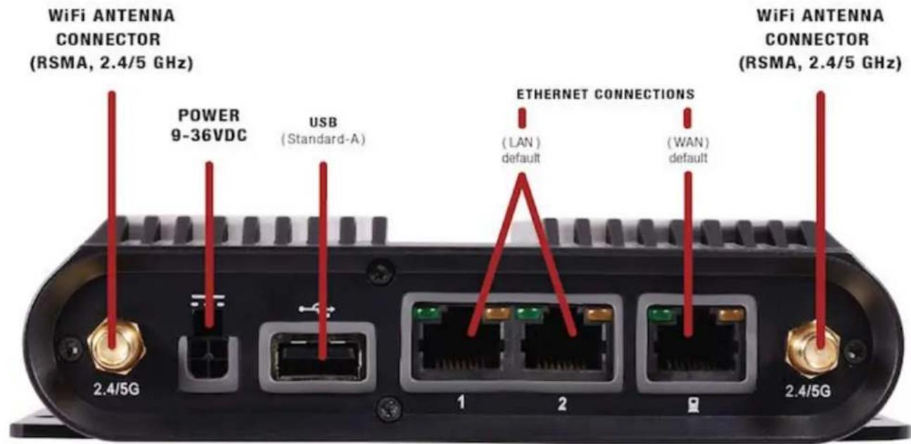

ANTENNA CONNECTORS – There are five total antenna connectors for the IBR1100 and three for the IBR1150.
• Two for the integrated 3G/4G modem (SMA)
• One for GPS (SMA)
• (IBR1100 only) Two for dual-band dual-concurrent WiFi (RSMA)
Be careful to correctly distinguish between SMA and RSMA connections. Antennas WITH pins must attach to connectors WITHOUT pins, while antennas WITHOUT pins must attach to connectors WITH pins.
Also, the MAIN modem connector may have better performance than the AUX connector, so attach the better (or single) modem antenna to the MAIN connector if that is relevant in your setup.
ETHERNET PORTS – By default there are two LAN Ethernet ports and one WAN Ethernet port. All three of these ports are LAN/WAN configurable.
POWER/GPIO CONNECTOR – This connector has four pin slots: power, ground, input, and output.
Connector pinout - view into router (rear view of cable connector):

| Pin Definition Details Wire Color | ||
| 1 Ground – Black | ||
| 2 Power 9–36 V DC Red | ||
| 3 Input 3 V input high threshold (36 V tolerant) Orange | ||
| 4 Output capable of sinking 250 mA Blue | ||
RESET (power and factory reset button)
- On – Press and hold for one second to turn on. Multiple LEDs turn on to signal that the router is on. RELEASE THE BUTTON BEFORE FIVE SECONDS TO PREVENT THE ROUTER FROM TURNING OFF AGAIN.
- Off – Press and hold for five seconds to turn off. The USB and modem lights turn red to signal that the router will turn off upon release. RELEASE THE BUTTON BEFORE TEN SECONDS TO PREVENT FACTORY RESET.
- Factory reset – Press and hold for ten seconds to factory reset the device. The USB and modem lights turn amber and blink twice to signal factory reset. This returns all settings to factory defaults.
NOTE: Using the reset button for turning the device on/off is typically unnecessary: the device powers on by default as soon as it receives power, and it can be configured to sense vehicle ignition with a timed delay for power off.
RS-232 (serial port) - This is a serial DE-9 (commonly called "DB-9"), 9-pin female connector. The pins are numbered from the top right as shown here:

Pin Signal Type
| 1 | RI |
| 2 TxD | |
| 3 RxD | |
| 4 DSR | |
| 5 GND | |
| 6 DTR | |
| 7 CTS | |
| 8 RTS | |
| 9 DCD |
LEDs

POWER
- Green = Powered ON.
- No Light = Not receiving power. Check the power switch and the power source connection.
- Flashing Amber = Attention. Open the administration pages (see Accessing the Administration Pages) and check the router status.

WiFi BROADCAST
These two LEDs indicate activity on the WiFi broadcast for both the 2.4 GHz and 5 GHz bands.
• 2.4G (green) = 2.4 GHz WiFi is on and operating normally.
- 5G (blue) = 5 GHz WiFi is on and operating normally.

EXTERNAL USB MODEM
Indicates the status of external USB modems.
Y - INTEGRATED MODEM
Indicates the status of integrated modems.
Both integrated and external USB modems have the following LED indicators:
- Green = Modem has established an active connection.
- Blinking Green = Modern is connecting.
• Amber = Modem is not active. - Blinking Amber = Data connection error. No modem connection possible.
- Blinking Red = Modem is in the process of resetting.
Y.11 - SIGNAL STRENGTH
Blue LED bars indicate the active modem's signal strength.
• 4 Solid Bars = Strongest signal.
• 1 Blinking Bar = Weakest signal. (A blinking bar indicates half of a bar.)
ADDITIONAL LED INDICATIONS
• The USB and modem lights turn amber and blink twice to signal factory reset.
- Two of the modem LEDs blink red in unison for 10 seconds when there is an error during firmware upgrade.
Quick Start
- Basic Setup
• Accessing the Administration Pages - First Time Setup Wizard
• Using Enterprise Cloud Manager
Basic Setup
1. Insert an activated SIM.
A wireless broadband data plan must be added to your CradlePoint COR IBR1100/IBR1150. Wireless broadband data plans are available from wireless carriers such as Verizon, AT&T, Sprint, EE, and Vodafone. The SIM must be provisioned with the carrier. Contact your carrier for details about selecting a data plan and about the process for provisioning your SIM.
Once you have an activated SIM, insert it into the integrated modem:

- Remove the bottom SIM cover (requires a small Phillips screwdriver).
- Slide the metal latch down to unlock the SIM cartridge. Use the cartridge marked SIM 1 first (use the other cartridge, SIM 2, for a secondary/backup SIM).
- Pull the cartridge upward, so it is standing at a 90° angle.
- Insert the SIM card with the metal contacts down and notch out.
- Press the cartridge back into place.
- Return the metal latch to the start (lock) position.
- Replace the bottom SIM cover. NOTE: Device will not power on without cover in place.
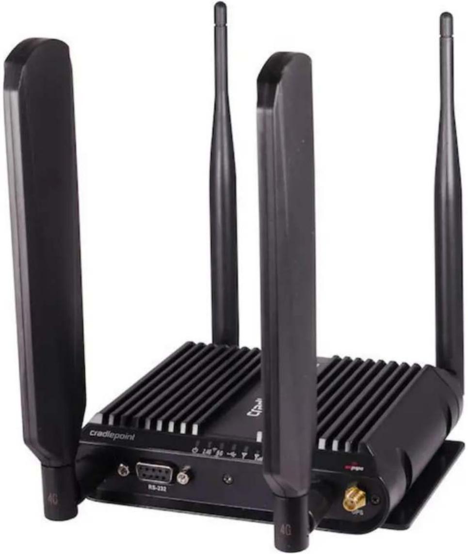
2. Attach modem/WiFi/GPS antennas.
Antennas are NOT included in the product package because of the diverse needs of customers. Both the COR IBR1100 and COR IBR1150 have two connectors for 3G/4G modem antennas (SMA) and one connector for GPS (SMA):

Additionally, the COR IBR1100 has two connectors for dual-band dual-concurrent 2.4/5 GHz WiFi (RSMA):

natural_image
Front view of a black wireless router with ports and connectors, labeled 2.4/5G (no additional text or symbols visible)See the CradlePoint antenna accessories page for recommended options for antennas. Also see the Antenna Ordering and Installation Guide, available as a PDF in the
Resources section of antenna and router product pages. Many network designs with the COR IBR1100/IBR1150 require remoted antennas with cables. Several factors affect antenna selection:
- require 3G/4G modem antennas only, or GPS/WiFi as well
• direct-attach, screw-mount, or magnetic-mount - size/shape limitations
• directional or omnidirectional
• performance in specific frequency ranges
This is a simple, standard antenna setup for direct-attach antennas for the COR IBR1100:
natural_image
Black CRADLEPOINT wireless router with three antennas and ventilation slots (no visible text or symbols on the device body)We recommend experimenting with different antenna orientations to see what works best in your environment (e.g., spreading one set of antennas out to a 45° angle). Do NOT allow antennas to lie flat on top of each other.
See the charts below for CradlePoint's default antenna recommendations for some common networking designs:
Basic Setup
| Antenna Type Recommended Antenna Part Number Suggested Amount | |||
| Modem Universal 3G/4G antenna 170649-000 2 | |||
| WiFi | Dual-band dual-concurrent 2.4/5. GHz WiFi antenna 170628-000 2 | ||
| GPS | GPS-GLONASS magnetic-mount antenna (includes 3M cable) | 170652-000 | 1 |
Vehicle Screw-Mount
| Antenna Type Recommended Antenna Part Number Suggested Amount | |||
| Modem, WiFi, & GPS | 5-in-1 screw-mount antenna (includes 3M cables)two 3G/4G modemtwo 2.4/5 GHz WIFIone GPS-GLONASS | 170654-000 1 | |
| Modem & GPS | 3-in-1 screw-mount antenna (includes 3M cables)two 3G/4G modemone GPS-GLONASS | 170653-000 1 | |
| GPS | GPS-GLONASS screw-mount antenna (includes 3M cable) | 170651-000 | 1 |
3. Connect to a power source.
The CradlePoint COR IBR1100/IBR1150 includes a two meter direct wire power and GPIO cable (shown below).

natural_image
Coiled black cable with connector and wiring, no visible text or symbolsThe GPIO cable can be attached to the fuse box in a vehicle. For detailed instructions on vehicle installations, see the COR IBR1100 Vehicle Installation Guide, available as a PDF in the Resources section of the CradlePoint COR IBR1100 Series product page.
If you want to plug into a wall power outlet, you'll need to purchase a separate wall power adapter: choose between the extended temperature range (-30 °C to 70 °C) and standard (0 °C to 40 °C) options. Most vehicle installations will use the included direct wire power/GPIO cable, which can be used to enable the ignition sensing feature, but there is also a car adapter option for plugging into a vehicle cigarette lighter receptacle.
Wall options
- COR IBR1100/IBR1150 extended temperature (-30 °C to 70 °C) 12VDC 2A locking power adapter – requires separate line cord (Part # 170648-000)
• Line cord for North America (Part # 170623-001)
• Line cord for EU (Part # 170623-002)
• Line cord for UK (Part # 170623-003)
COR 12VDC 2A locking power adapter with 0 °C to 40 °C temperature range – includes US, EU, and UK plugs (Part # 170584-002)
NOTE: CradlePoint primarily recommends the extended temperature adapter because it covers the COR IBR1100/IBR1150 full temperature range of -30^ to 70^ . Cost-sensitive customers that intend to use the IBR1100/IBR1150 in temperature-controlled office.
environments can order the 170584-002 adapter, but it limits the operating temperature range to 0 °C to 40 °C .
Vehicle options
• Vehicle locking power adapter for COR (Part # 170635-000)
- Two meter locking power and GPIO cable (direct wire) for replacement – included by default (Part # 170585-000)
4. Connect to a computer or other network equipment.
Connect wirelessly to the WiFi broadcast or with an Ethernet cable connected to your computer and plugged into one of the default Ethernet LAN ports (numbered 1–2).
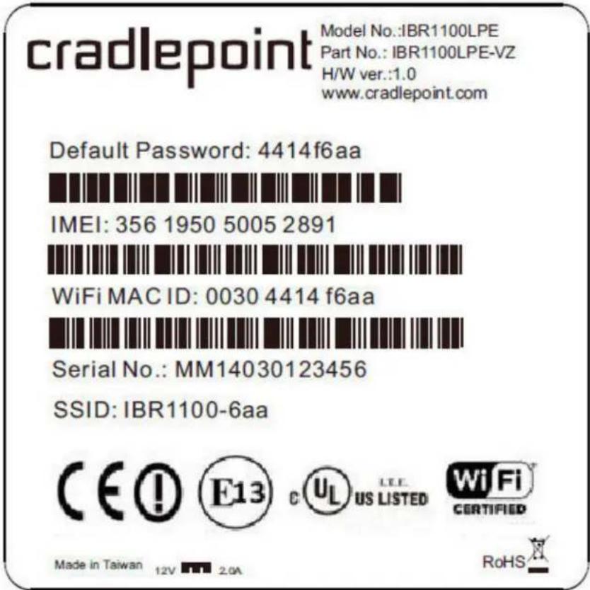
The default WiFi network name broadcast is "IBR1100-xxx", where "xxx" is the last three characters of your router's MAC address (this is the SSID on the product label). To connect to the WiFi, you will need to input the DEFAULT PASSWORD when prompted. The DEFAULT PASSWORD is provided on the product label found on the bottom of your router.
NOTE: The product label below is an example only: your DEFAULT PASSWORD and SSID will be unique.
Accessing the Administration Pages
Once you are connected, open the GUI-based administration pages to make configuration changes to your router.
cradlepoint
natural_image
Black electronic device with ventilation grilles and ports (no visible text or symbols)Administrator Login
You are connected to a CradlePoint IBR110iter. Please enter your administrator; password blow to access settings and options.
Enter Password
Password:

Router Details
Model Number:
2100
Internet Connection:
Connected
Wireless Details
Status:
Enabled
Clients:
3 Clients
Radio #1 Channel:
1
Name:
AAAAA 2.4GHz
Radio #2 Channel:
157
Name:
AAAAA 5GHz
Modem Details
Manufacturer Model
Signal Mode
CradlePoint
Internal LPE
-97 dBm Not Reported
CradlePoint
Internal LPE
Not Reported
Copyright © CradlePoint Technology, Inc. 2014 All rights reserved.
wipipe.
- Open a browser window and type "cp/" or "192.168.0.1" in the address bar. Press ENTER/RETURN.
- When prompted for your password, type the eight character DEFAULT PASSWORD found on the product label.
cradlepoint
Model No.: IBR1100LPE
Part No.: IBR1100LPE-VZ
H/W ver.:1.0
www.cradlepoint.com
Default Password: 4414f6aa

IMEI: 356 1950 5005 2891

WiFi MAC ID: 0030 4414 f6aa

Serial No.: MM14030123456
SSID: IBR1100-6aa


US LISTED

CERTIFIED
RoHS

It's possible – and more efficient – to do all your configuration changes through CradlePoint Enterprise Cloud Manager (ECM) without logging into the local administration pages. Set up a group of routers and set the configuration for all of them at once. See below for more information about ECM.
First Time Setup Wizard
When you log in for the first time, you will be automatically directed to the FIRST TIME SETUP WIZARD, which will walk you through the steps to customize your CradlePoint COR IBR1100/IBR1150. You have the ability to configure any of the following:
- Administrator Password
- Time Zone
- WiFi Network Name
• Security Mode
• Access Point Name (APN) for SIM based modems
• Modem Authentication - Failure Check
If you are currently using the router's WiFi network, you will need to reconnect your devices to the network using the newly established wireless network name and password.
NOTE: To return to the First Time Setup Wizard after your initial login, select GETTING STARTED on the top navigation bar and FIRST TIME SETUP in the dropdown menu.
Using Enterprise Cloud Manager
Rapidly deploy and dynamically manage networks at geographically distributed stores and branch locations with Enterprise Cloud Manager, CradlePoint's next generation management and application platform. Enterprise Cloud Manager (ECM) integrates cloud management with your CradlePoint devices to improve productivity, increase reliability, reduce costs, and enhance the intelligence of your network and business operations.
Click here to sign up for a free 30-day ECM trial.
Depending on your ordering process, your devices may have already been bulk-loaded into ECM. If so, simply log in at . cradepointecn.com using your ECM credentials and begin managing your devices seamlessly from the cloud.
If your device has not yet been loaded into your ECM account, you need to register. Log into the device administration pages and go to Getting Started → Enterprise Cloud Manager Registration. Enter your ECM username and password, and click on "Register".
Register this router with the CradlePoint Enterprise Cloud Manager (ECM) Service.
To register this router with CradlePoint ECM you must first have an account. If you need to create an account you can signup here.
Once you've created an account, or if you already have one, you can enter your ECM username and password to register this router.
ECM Username:

ECM Password:

Register
Once you have registered your device, go to cradlepointecm.com and log in using your ECM credentials.
For more information about how to use CradlePoint Enterprise Cloud Manager, see the following:
• Getting Started
• ECM on the Knowledge Base
Navigating the Administration Pages
To access the administration pages, open a web browser and type the hostname "cp/" or IP address "http://192.168.0.1" into the address bar. The Administrator Login page appears.
cradlepoint
natural_image
Black electronic device with ventilation slots and ports (no visible text or symbols)Administrator Login
You are connected to a CradlePoint IBR110iter. Please enter your administrator; password blow to access settings and options.

Router Details
Model Number:
2100
Internet Connection:
Connected
Wireless Details
Status:
Enabled
Clients:
3 Clients
Radio #1 Channel:
1
Name:
AAAAA 2.4GHz
Radio #2 Channel:
157
Name:
AAAAA 5GHz
Modem Details
Manufacturer Model
CradlePoint
Internal LPE
CradlePoint
Internal LPE
Signal Mode
-97 dBm Not Reported
Not Reported
Copyright © CradlePoint Technology, Inc. 2014 All rights reserved.
wipipe.
Log in using your administrator password. Initially, this password can be found on the bottom of the router as the Default Password (this password is also the last eight digits of the unit's MAC address). You may have changed the administrator password during initial setup using the First Time Setup Wizard. If so, log in using your personalized administrator password.
If you have forgotten your personalized password, you can reset the device to the factory default configuration. When you reset the router, the administrator password will revert back to the Default Password. Press and hold the reset button on the router unit until the lights flash (approximately 10-15 seconds). You can then log in using the Default Password.
Quick Links
The CradlePoint logo in the top left corner of all the administration pages is a link to the Dashboard (Status → Dashboard), which displays fundamental information about the router.
cradlepoint
The black bar across the top provides quick access to important information and controls:
Internet Connection


WiFi Clients

Logout
- Internet Connection – This links to Status → Internet Connections where you can view in-depth information about your Internet sources.
- Click on this green dot to link to Internet → Connection Manager where you can manage your WAN interfaces.
- Click on the green image of signal strength bars to open a "Modem Connection Quality" popup window that shows the strength of your Internet signal:
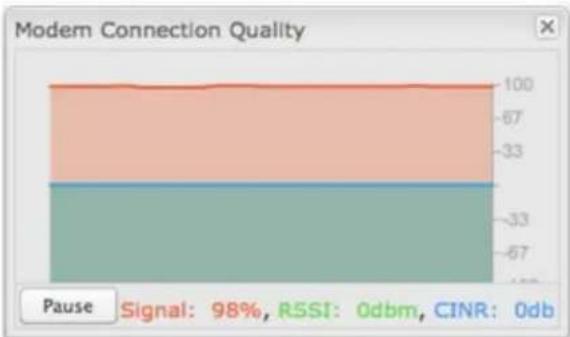
bar_stacked
Modern Connection Quality | Category | Value | |---|---| | Top Layer | -67 | | Middle Layer | -33 | | Bottom Layer | -33 | Pause Signal: 98%, RSSI: 0dbm, CINR: 0db- WiFi Clients – Click to view a signal strength indicator for you network, "WiFi Connection Strength".
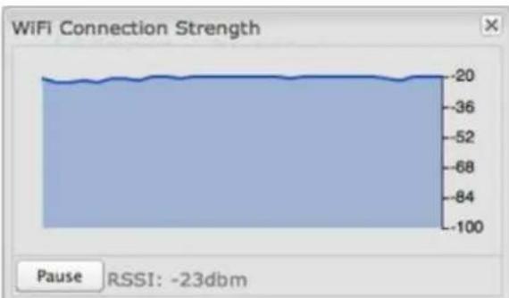
line
| Time | WiFi Connection Strength | | ---- | ------------------------ | | 0 | -20 | | 1 | -20 | | 2 | -20 | | 3 | -20 | | 4 | -20 | | 5 | -20 | | 6 | -20 | | 7 | -20 | | 8 | -20 | | 9 | -20 | | 10 | -20 | | 11 | -20 | | 12 | -20 | | 13 | -20 | | 14 | -20 | | 15 | -20 | | 16 | -20 | | 17 | -20 | | 18 | -20 | | 19 | -20 | | 20 | -20 | | 21 | -20 | | 22 | -20 | | 23 | -20 |- The number listed in the orange block shows the number of attached clients. Click this to go to the Client List page (Status → Client List).
- Logout – Click to log out of the administration pages.
Configuration Pages
The following table shows the navigation layout of the administration pages. Click on the tabs along the top bar to reveal the following dropdown menus.
| Getting Started | Status | Network Settings | Internet | System Settings |
NOTE: These contents vary by product. Not all items are shown for all products.
| Getting Started Status Network Settings Internet System Settings | ||||
| Enterprise Cloud Manager RegistrationFirst Time SetupIP Passthrough Setup | Client ListDashboardGPSGRE TunnelsHotspotClientsInternetConnectionsRoutingStatisticsSystem LogsVPN TunnelsWiPipe QoS | Content FilteringDHCP ServerDNSFirewallMAC Filter / LoggingRoutingRoutingProtocolsWiFi / Local NetworksWiPipe QoS | Connection ManagerClient Data UsageData UsageGRE TunnelsL2TP TunnelsNetwork Mobility (NEMO)NHRP InterfacesOpenVPN Tunnels (coming Q4)VPN TunnelsWAN Affinity / Load BalancingWiFi as WAN / Bridge | AdministrationCertificate ManagementDevice AlertsGPIO ConnectorEnterprise Cloud ManagerFeature LicensesHotspot ServicesSerial RedirectorSNMPConfigurationSystem ControlSystem Software |
• Enterprise Cloud Manager Registration
- First Time Setup
• IP Passthrough Setup
- Client List
- Dashboard
• GPS
• GRE Tunnels - Hotspot Clients
- Internet Connections
- Routing
• Statistics - System Logs
• VPN Tunnels -
WiPipe QoS
-
Content Filtering
- DHCP Server
DNS - Firewall
• MAC Filter / Logging - Routing
- Routing Protocols
• WiFi / Local Networks -
WiPipe QoS
-
Connection Manager
- Client Data Usage
- Data Usage
• GRE Tunnels
• L2TP Tunnels
• Network Mobility (NEMO) - NHRP Interfaces
• OpenVPN Tunnels (coming Q4) - VPN Tunnels
• WAN Affinity / Load Balancing -
WiFi as WAN / Bridge
-
Administration
• Certificate Management
• Device Alerts - GPIO Connector
• Enterprise Cloud Manager - Feature Licenses
- Hotspot Services
- Serial Redirector
• SNMP Configuration - System Control
- System Software
Getting Started – Enable fundamental functionality through these setup wizards, including the First Time Setup Wizard.
Status – Displays various types of information about your router such as a list of clients that are attached to your networks (Client List), the details of each Internet source your router is using (Internet Connections), and a map of your router's location (GPS). Very few changes can be made from this tab; the primary purpose is to display information.
Network Settings – Provides configuration options for the networks, or LAN, created by your router. For example, enable a guest WiFi network (WiFi / Local Networks), set up rules to filter websites (Content Filtering), or create a traffic-shaping rule to set bandwidth priorities (WiPipe QoS).
Internet – Provides configuration options for the Internet sources, or WAN, used by the router. For example, you can set up a rule to track how much data you are using per month on a modem (Data Usage) or set the failover order for your Internet sources (Connection Manager).
System Settings – Provides broad administrative controls. For example, you can set up a Terms of Use page for your guest network (Hotspot Services), enable remote management of the router (Administration), or upgrade firmware (System Software).
Getting Started
• Enterprise Cloud Manager Registration
- First Time Setup
IP Passthrough Setup
Enterprise Cloud Manager Registration
CradlePoint Enterprise Cloud Manager is CradlePoint's next generation management and application platform. Enterprise Cloud Manager (ECM) integrates cloud management with your CradlePoint devices to improve productivity, increase reliability, reduce costs, and enhance the intelligence of your network and business operations.
Click here to learn more and sign up for a free 30-day ECM trial.
Depending on your ordering process, your devices may have already been bulk-loaded into ECM. If so, simply log in at cradepointecm.com using your ECM credentials and begin managing your devices seamlessly from the cloud.
If your device has not yet been loaded into your ECM account, you need to register. Log into the device administration pages and go to Getting Started → Enterprise Cloud Manager Registration. Enter your ECM username and password, and click on "Register".
Register this router with the CradlePoint Enterprise Cloud Manager (ECM) Service.
To register this router with CradlePoint ECM you must first have an account. If you need to create an account you can signup here.
Once you've created an account, or if you already have one, you can enter your ECM username and password to register this router.
ECM Username:
ECM Password:
Register
Once you have registered your device, go to https://cradlepointecm.com and log in using your ECM credentials.

For more information about how to use CradlePoint Enterprise Cloud Manager, see the following:
• Getting Started
• ECM on the Knowledge Base
First Time Setup
When you log in for the first time, you will be automatically directed to the FIRST TIME SETUP WIZARD, which will walk you through basic steps to customize your router. To return to the First Time Setup Wizard after your initial login, go to Getting Started → First Time Setup in the dropdown menu. You have the ability to configure any of the following:
• Administrator Password
- Time Zone
- WiFi Network Name
- Security Mode
• Access Point Name (APN) for SIM-based modems
- Modem Authentication
- Failure Check
Administrator Password
CradlePoint recommends that you change the router's ADMINISTRATOR PASSWORD, which is used to log into the administration pages. The administrator password is separate from the WiFi security password, although initially the Default Password is used for both.
Administrator Password
To secure your router, please set and verify the administrator password below.
Your default password is printed on the product sticker found on the back of your product. The administrator password allows you to modify all router settings.
This is separate from the WiFi security password (if applicable).
Administrator Password:
Verify password:
If you plan to use your router in a PCI DSS compliant environment, do not use this setting. Use the Administration -> Advanced Security Mode setting instead.
NOTE: If you plan to use your router in a PCI DSS compliant environment, do not use this setting. Use the "Advanced Security Mode" settings under the Router Security tab in System Settings → Administration instead.
Time Zone
You can select your TIME ZONE from a dropdown list. (This may be necessary to properly show time in your router log, but typically your router will automatically determine your time zone through your browser.)
Time Zone
Selecting your Time Zone allows the router to keep the proper date and time for your location.
Time Zone: (UTC -7) Mountain
Click NEXT.
WiFi Network Name
CradlePoint recommends that you customize your WiFi network name. Type in your personalized network name here. You can also enable the Guest Network feature (for more configuration options, see Network Settings → WiFi / Local Networks).
WiFi Network Name
Your wireless network name can be any personalized word or phase. The name you select will identify your network when connecting to WiFi.
When you select Enable Guest Network, you will create a second public WiFi broadcast from your router, allowing guests to simply and easily use your connection.
Wireless Network Name: AAAAA 2.4GHz
Enable Guest Network: □
WiFi Security Mode
Security Mode
In order to protect your network from unauthorized users, it is highly recommended you choose the highest level of security that your attached devices will support.
CradlePoint recommends the WPA2 security mode.
If you select an advanced security mode and are unable to connect to the router after saving your new settings, you can return your router to its original factory settings by pressing the Reset button (found on the side of your router) for ten seconds. This will restore your password to the last eight characters of your MAC address.
Security Mode: GOOD (WPA1/WPA2)
WPA Password:
WPA Password (confirm): ....
Choose the WIFI SECURITY MODE that best fits your needs:
- BEST (WPA2): Select this option if your wireless adapters support WPA2-only mode. This will connect to most new devices and is the most secure, but may not connect to older devices or some handheld devices such as a PSP.
• GOOD (WPA1 & WPA2): Select this option if your wireless adapters support WPA or WPA2. This is the most compatible with modem devices and PCs. - POOR (WEP): Select this option if your wireless adapters only support WEP. This should only be used if a legacy device that only supports WEP will be connected to the router. WEP is insecure and obsolete and is only supported in the router for legacy reasons. The router cannot use 802.11n modes if WEP is enabled; WiFi performance and range will be limited.
- NONE (OPEN): Select this option if you do not want to activate any security features.
CradlePoint recommends BEST (WPA2) WiFi security. Try this option first and switch only if you have a device that is incompatible with WPA2.
Choose a personalized WPA PASSWORD or WEP KEY. This password will be used to connect devices to the router's WiFi broadcast once the security settings have been saved.
- WPA Password: The WPA Password must be between 8 and 64 characters long. A combination of upper and lower case letters along with numbers and special characters is recommended to prevent hackers from gaining access to your network.
- WEP Key: A WEP Key must be either a hexadecimal value of 5 or 13 characters or a text value of 10 or 26 characters.
Click NEXT.
Access Point Name (APN)
Access Point Name (APN)
If you are using a SIM-based modem (LTE/GSM/HSPA) with your CradlePoint router you may need to configure the APN before it will properly connect to your carrier. Wireless carriers offer several APNs so check with your carrier to confirm the appropriate one to use.
Access Point Name (APN): ⚙ Default
○ Manual
DON'T USE THIS APN WIZARD if you have already configured an APN. Any specific modem settings will not be overwritten by this generic APN setup. Leave this setting as default and after finishing this Wizard go to the Connection Manager page, select your modem, and edit the settings. The SIM PIN/APN tab has more available settings than are provided here.
If you are using a SIM-based modem (LTE/GSM/HSPA) with your CradlePoint router, you may need to configure the APN before it will properly connect to your carrier. Wireless carriers offer several APNs, so check with your carrier to confirm the appropriate one to use. Some examples include:
- AT&T: "broadband"
• T-Mobile: "epc.lmobile.com"
• Rogers LTE: "IteinternetLapn" - Bell: "inet.bell.ca"
- TELUS: "isp.telus.com"
You can either leave this on the Default setting or select Manual and input a specific APN.
If your specific modem or SIM already has APNs programmed into it, you should leave this on the Default setting. After finishing this Wizard go to Internet → Connection Manager, select your modem, and edit the settings. The SIM PIN/APN tab has more available settings than are provided here.
Modem Authentication
Some modems require a username and password to be entered to authenticate with a carrier. Do not fill in these fields unless you are sure your modem needs authentication.
Modem Authentication
Some modems require a username and password to be entered to authenticate with a carrier. Do not fill in these fields unless you are sure your modem needs authentication.

- Authentication Protocol – Set this only if your service provider requires a specific protocol and the Auto option chooses the wrong one. Select from:
Auto
- Pap
- Chap
- Username
- Password
Configuring Failure Check
It is possible for a WAN interface to go down without the router recognizing the failure. (For example: the carrier for a cellular modem goes dormant, or your Ethernet connection is properly attached to a modem but the modem becomes disconnected from its Internet source.) Enable Failure Check to ensure that you can get out to the Internet via your primary WAN connection. This option is disabled by default because it may use data unnecessarily. Use this in combination with failover. For cellular modems, use this in combination with Aggressive Reset (Internet → Connection Manager under Modem Settings in the interface/rule editor).
Enable and configure Failure Check
Failure check will test the connection to verify the WAN device is connected.

Idle Check Interval: Set the number of seconds the router will wait between checks to see if the WAN is still available. (Default: 30 seconds. Range: 10-3600 seconds.)
Monitor while connected: Select from the dropdown menu. (Default: Off.)
- Active Ping: A ping request will be sent to the Ping Target. If no data is received, the ping request will be retried 4 times at 5-second intervals. If still no data is received, the device will be disconnected and failover will occur. When "Active Ping" is selected, the next line gives an estimate of data usage in this form: "Active Ping could use as much as 9.3 MB of data per month." This amount depends on the Idle Check Interval.
- Off: Once the link is established the router takes no action to verify that it is still up.
Ping IP Address: If you selected "Active Ping", you will need to input an IP address that will respond to a ping request. This IP address must be an address that can be reached through your WAN connection (modem/Ethermet). Some ISPs/Carriers block certain addresses, so choose an address that all of your WAN connections can use. For best results, select an established public IP address. For example, you might ping Google Public DNS at 8.8.8.8 or Level 3 Communications at 4.2.2.2.
Click NEXT.
Summary
Review the details and record your wireless network name, administrative password, and WPA password (or WEP key). Move your mouse over your WIFI password to reveal it.
Summary
Below is a detailed summary of your system settings. Please record these newly established router settings for future access.
When you are satisfied with the configuration, select the 'Apply' button below.
Administrator Password:
Time Zone: (UTC -7) Mountain
Wireless Network Name: AAAAA 2.4GHz
Enable Guest Network: Yes
Security Mode: GOOD (WPA1/WPA2)
WPA Password:
Access Point Name (APN): Default (router will choose APN automatically)
Authentication Protocol:
Username:
Password:
Failure Check: Off

Please record these settings for future access. You may need this information to configure other wireless devices.
NOTE: If you are currently using the device's WiFi network, reconnect to the network using the new wireless network name and security password.
Click APPLY to save the settings and update them to your router.
IP Passthrough Setup
You can quickly enable IP passthrough with the IP Passthrough Setup Wizard available under Getting Started → IP Passthrough Setup. IP passthrough takes a 3G/4G WAN data source (USB, ExpressCard, or CradlePoint business-grade modem) and passes the IP address through to Ethernet LAN.
Using this function requires many changes to your router configuration. The IP Passthrough Setup Wizard will automatically make these changes for you: simply read through the wizard and select Enable IP Passthrough on the second page. For further configuration options, see Network Settings → WiFi / Local Networks.
Review the list of changes to ensure they are compatible with your router needs:
• All Ethernet ports will be set to LAN (i.e. you cannot use Ethernet as an Internet source for your router).
- All WAN devices will have Load Balance disabled and the highest priority device will be used.
• All network groups except the primary network group will be removed.
- All wireless interfaces will be removed from the primary network group. (It is possible to have a wireless interface associated with another network.)
• All router-based VPN and GRE services will be disabled.
- The Routing Mode will be set to IP Passthrough. (Network Settings → WiFi / Local Networks in the "Local Network Editor" under "IP Settings")
- The Subnet Selection Mode will be set to "Automatically Create Subnet" (Network Settings → WiFi / Local Networks in the "Local Network Editor" under "IP Settings" — this shows once IP Passthrough is set as the Routing Mode). You have the option to override this and select Force 24 Subnet, which forces a subnet of 255.255.255.0 and uses the first available address in the network as the gateway. This is for compatibility with equipment that may not handle modem addressing schemes; this should not be used unless necessary.
Any Ethernet WAN connections should be disconnected before IP passthrough is enabled.
Status
The Status section of the Administration Pages displays information about many different aspects of the router. The Status tab has the following dropdown menu items:
- Client List
- CP Secure Connect
- Dashboard
GPS
GRE Tunnels - Hotspot Clients
- Internet Connections
Routing
• Statistics - System Logs
• VPN Tunnels - WiPipe QoS
Client List
The Client List displays the specifications of each device connected to your router, including wireless and wired clients.
| Hostname | IP | MAC | Connection | Time Onl... | ||
| jcramer-osx | 192.168.0.87 | e4:ce:8f:13... | 802.11n, 20 MHz, 114 Mbp... | 1:11:55 | Kick | Block MAC |
| drush-le6500 | 192.168.0.86 | 00:26:5e:4... | 802.11n, 20 MHz, 141 Mbp... | 3:06:15 | Kick | Block MAC |
| Wired Clients | ||||||
| Hostname | IP | MAC | ||||
Wireless Clients
For each device using a wireless connection to your router, the following information is displayed: Hostname, IP, MAC, Connection, and Time Online.
Wired Clients
For each device using a wired connection to your router, the following information is displayed: Hostname, IP, and MAC.
Client List Fields
Hostname: The name by which each computer or device in a network is known.
IP: The "IP address," or "Internet Protocol address," specifies a location for each device.
MAC: This is the "MAC address", a factory-assigned identifier used to identify a specific attached computer or device.
Connection: Summary of the wireless connection. For example: 802.11n, 20 MHz, 130 Mbps, -26 dBm
- 802.11n: The transmission standard being used by the client. Possible values include 802.11a, 802.11b, 802.11g, and 802.11n. 802.11n is the newest and best standard, but some older devices may not support it.
- 20 MHz: This is the channel width that defines the theoretical data rate (in megahertz) that the attached computer or device can send to or receive from the router. The channel width is set in Network Settings → WiFi / Local Networks. Typically this will be 20 MHz, but 40 MHz is possible if the router is set to use two adjacent 20 MHz channels. A wider channel can mean better performance, but not if there is too much interference. Even if 40 MHz is set in the WiFi Channel Width, the router may still fall back to 20 MHz if interference is found.
- 130 Mbps: The transmit rate (in megabits per second) currently used to transmit packets from the router to the client. This rate changes automatically to match environmental conditions. Distance from the router, interference, etc can impact this value. Higher values indicate better performance. Devices can still function in the network with as little as 1 Mbps.
- -26 dBm: A relative measure of wireless signal quality (decibels relative to one milliwatt). This expresses theoretical best quality. The value is given as a negative exponent: -20 is a very good value while -80 is relatively poor. Signal quality can be reduced by distance, by interference from other radio frequency sources (such as cordless telephones or neighboring wireless networks), and by obstacles between the router and the wireless device.
Time Online: Simply the amount of time the device has been connected to the router.
Kick: Click on this button to disconnect a client. This will remove all wireless access for a user. The access will be restored when the router is rebooted. To block a client permanently use the Block MAC option or add the address to the MAC Filter under Network Settings → MAC Filter / Logging.
Block MAC: Click on this button add the MAC address to the list of blocked MAC addresses under Network Settings → MAC Filter / Logging. If the MAC Filter is set to act as a whitelist, then the address will be removed from the list of allowed clients. Clients may remain visible in the Client List after being blocked, but traffic for that client is blocked immediately. To restore access edit the list of MAC addresses under Network Settings → MAC Filter / Logging.
CP Secure Connect
View the status of configured CP Secure Connect tunnels.
| Name | Status | Transmit (packets/bytes) | Receive (packets/bytes) |
To set up or edit a CP Secure Connect tunnel, go to Internet → VPN Tunnels.
NOTE: CP Secure Connect requires a feature license.
Dashboard
The Dashboard shows fundamental information about your router, divided into the following basic categories:
- Router Information
- Internet
- Local Networks
- WiFi Networks

Router Information :: (Detailed Info)
Product: 2100
Serial: MM130459300029
Firmware: v5.0.0 (Fri Oct 11 03:30:45 MDT 2013)
Build Date: Fri Oct 11 03:30:45 MDT 2013
MAC Address: 00:30:44:16:c7:c1
CPU Usage: 3%
Up Time: 5 days, 3 hours, 23 mins
Clock: Wed Oct 16 2013 13:00:42 GMT-0600 (MDT)

Internet :: (Detailed Info)
State: Connected
WAN Type: Ethernet
Connection Type: DHCP
Connected Time: 5 days, 3:23:23
IP Address: 172.21.2.154
Gateway: 172.21.2.1
DNS Servers: 172.21.21.36, 172.21.21.29

Local Networks :: (Detailed Info)
Clients: 2
Primary LAN: 192.168.0.1/255.255.255.0
IPv6 None
Address:
Route Mode: NAT (Network Address Translation)
Access: Admin Access, UPnP, DHCP
Guest LAN: 192.168.10.1/255.255.255.0
IPv6 None
Address:
Route Mode: NAT (Network Address Translation)
Access: LAN Isolation, UPnP, DHCP

WiFi Networks :: (Detailed Info)
WiFi Radio Channel: 11, 100% Transmit Power #1:
Channel 56% (Moderate) Contention:
SSID: AAAAA 2.4GHz
Security: WPA1/WPA2 Personal
Network: Primary LAN
WiFi Radio Channel: 36, 100% Transmit Power #2:
Channel 8% (Low) Contention:
SSID: AAAAA 5GHz
Security: WPA1/WPA2 Personal
Network: Primary LAN
For more in-depth information and/or configuration options, click on the Detailed Info link beside the category title. For each category, this links to
- Router Information – System Settings → Administration
- Internet – Internet → Connection Manager
- Local Networks – Network Settings → WiFi / Local Networks
• WiFi Networks – Network Settings → WiFi / Local Networks
After the initial setup of the router, every time you log in you will automatically be directed to this Dashboard. Also, you can click on the CradlePoint logo in the upper left-hand corner to return to the Dashboard from any page.
cradlepoint
Router Information
"Detailed Info" links to System Settings → Administration.
• Product – Gives the product name
- Serial – Device serial number
- Firmware – Gives the number of the current firmware version
• Build Date – Year-month-day-hours-minutes seconds for the most recent firmware upgrade
• MAC Address – The router's unique identifier
• CPU Usage – Expressed as a percentage
• Up Time – Total time for current session
• Clock – Current local date and time
To check for firmware upgrades, see: System Settings → System Software
Internet
"Detailed Info" links to Internet → Connection Manager.
• State – Connected/Disconnected
• Signal Strength – Expressed as a percentage (Signal Strength is not included if Ethernet is the WAN type)
• WAN Type – Ethernet, Modem, or WiFi as WAN
- Connection Type – Possibilities include: DHCP (for Ethernet), HSPA, LTE, WiMAX, etc.
- Connected Time – The time the current Internet source (WAN) has been connected
IP Address
- Gateway
• DNS Servers
The IP address and gateway describe your active WAN source. For configuration options, see Internet → Connection Manager. For DNS server configuration options, see: Network Settings → DNS.
Local Networks
"Detailed Info" links to Network Settings → WiFi / Local Networks.
- Clients – The number of current clients
For each network, the following information is displayed:
• Network Name: IP Address/Netmask
- IPv6 Address – Displays if enabled
- Route Mode – NAT (Network Address Translation), Standard (NAT-less), Hotspot, or Disabled
- Access – Admin Access, LAN Isolation, UPnP (Universal Plug and Play), and/or DHCP
To configure a network, see: Network Settings → WiFi / Local Networks
WiFi Networks
"Detailed Info" links to Network Settings → WiFi / Local Networks.
For each enabled WiFi radio (2.4 GHz and 5 GHz if available), the following information is displayed:
- WiFi Radio: Channel – 1-11 for 2.4 GHz; 36, 40, 44, 48, 149, 153, 157, 161, or 165 for 5 GHz; Transmit Power (expressed as a percentage)
• Channel Contention – Displayed as a bar graph by percentage (lower numbers are better; lower numbers mean that there are fewer competing signals).
For each WiFi network, the following information is displayed:
- SSID – Service Set Identifier: an identifier or name for a wireless network
- Security – WPA2/WPA1/WEP Personal/Enterprise or Open; Isolated Clients
- Network – Admin Access, LAN Isolation, UPnP (Universal Plug and Play), and/or DHCP
To configure WiFi network settings, see: Network Settings → WiFi / Local Networks.
Router Alerts
On the right side of the Dashboard page is a brief set of "Router Alerts" that state basic information such as whether the router is running properly. This will inform you about the availability of new firmware, for example.
Router Alerts
The router is running properly
Router firmware is updated from the System Software page.
Load balancing and Failover can be configured in the Connection Manager.
Product Support Help
Router Alerts includes links to System Settings → System Software (for new firmware) and Internet → Connection Manager.
GPS
If a modem capable of providing GPS coordinates is connected and GPS support is enabled, this page will show a graphical view of your router's location. See the GPS section in System Settings → Administration to enable GPS support.
Status / GPS Status
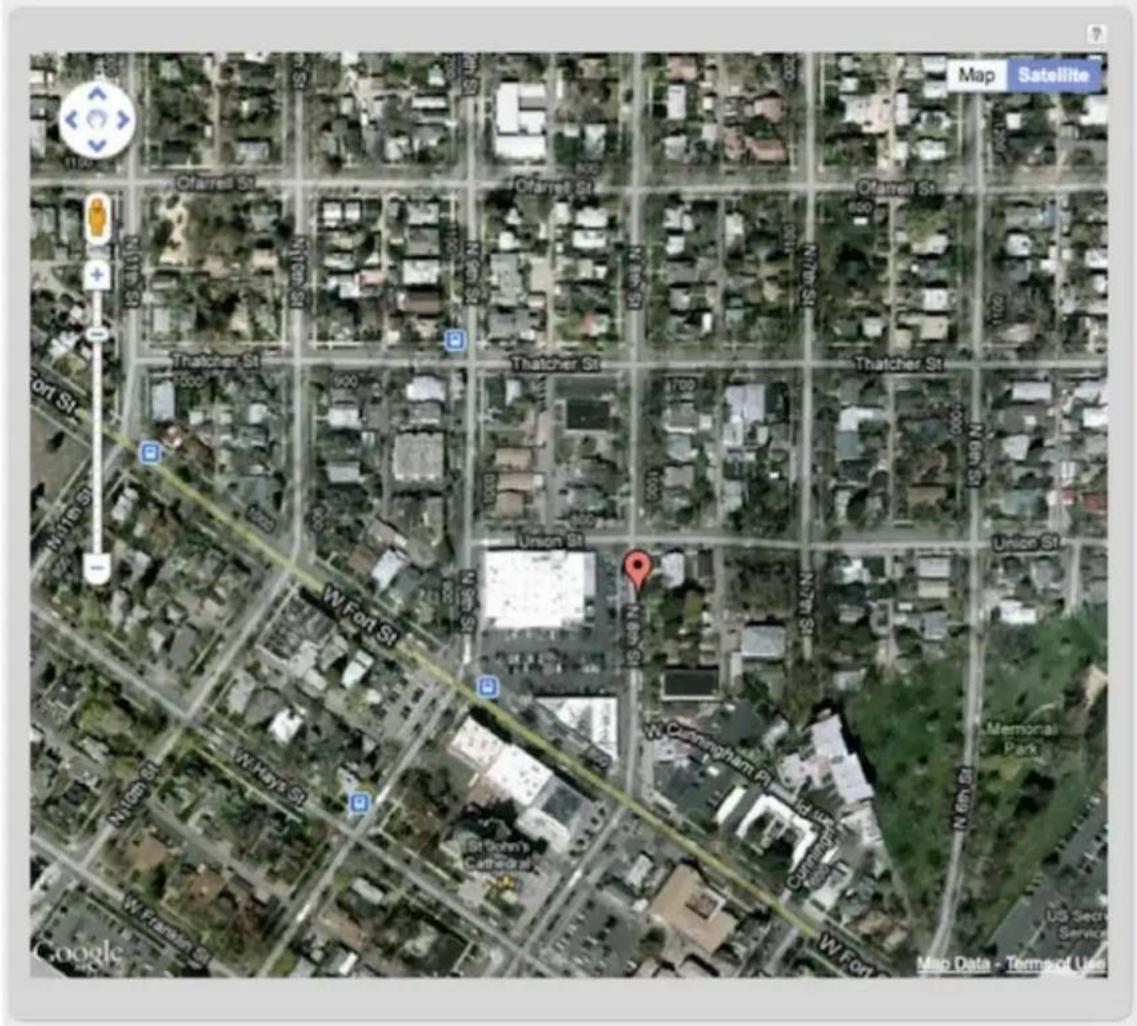
GPS information is only displayed if 1) the modem supports GPS, 2) your carrier allows the GPS functionality, and 3) the modem has sufficient GPS signal strength. If no information is displayed, check that both the modem and your carrier support GPS. If GPS is supported, make sure the modem is in an area where it can receive a signal
from the GPS satellites.
GRE Tunnels
View the status of configured GRE Tunnels. To set up or edit a GRE tunnel, go to Internet → GRE Tunnels
Included information:
Name
- Status
• Transmit (packets/bytes)
- Receive (packets/bytes)
MTU
| GRE Tunnels | ||||
| Name | Status | Transmit (packets/byt... | Receive (packets/bytes) | MTU |
Hotspot Clients
View the status of the clients that have logged in through the Hotspot/Captive Portal. View:
- Hostname
IP address - MAC address
• Data Usage (both IN and OUT)
Time Online
| Hostname | IP | MAC | Data Usage | Time Online | |
| 00-23-6c-7d-07-d5 | 192.168.10.134 | 00-23-6c-7d-07-d5 | 2.7 MB IN 237.4 KB OUT | 0:01:57 | Revoke |
You may revoke a client's access to the Internet by clicking the 'Revoke' button.
Internet Connections
The Internet Connections submenu option provides a list of attached WAN devices used as the Internet source for the router.
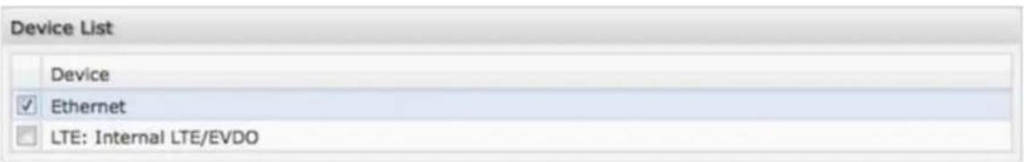
Select one of these devices to see detailed information about that particular device. Possible devices include:
- Ethernet
- 3G/4G modem
- WiFi as WAN
The information displayed varies greatly depending on the technology, especially for 3G/4G modems. CradlePoint passes on the information provided by the modems, which is specific to the carrier (e.g. Verizon) and technology (e.g. LTE).
Ethernet example:
| Device Information: Broadcom 47xx Robo-Switch | |
| Property | Value |
| General Information | |
| Unique Identifier | wan |
| Model | 47xx Embedded |
| Type | ethernet |
| Port | eth0 |
| IPv4 Information | |
| IP Address | 172.21.2.154 |
| Gateway | 172.21.2.1 |
| DNS Servers | 172.21.21.36,172.21.21.29 |
| Statistics | |
| Incoming Bytes | 1326138100 |
| Outgoing Bytes | 217959902 |
| Connection Uptime | 5 days, 7:38:20 |
3G/4G modem example:
| Property | Value |
| Diagnostics | |
| Signal Error Rate | N/A |
| Modem Firmware Version | SWI9200X_01.00.03.01AP R2748 CARMD-EN-10526 2011/07/25 19:31:25 |
| Battery status | 0 |
| CGSN | |
| Service Display | HSPA |
| Carrier Status | DOWN |
| MDN | |
| PIN Status | READY |
| ESN/IMEI | |
| Product | Internal LTE/HSPA+ |
| Signal Strength(dBm) | -65 |
| Default Profile | 1 |
| Model | Internal LTE/GSM |
| Manufacturer | CradlePoint Inc. |
| Battery level | 100 |
| General Information | |
| Model | Internal LTE/GSM |
| Unique Identifier | |
| Port | int1 |
| Profile 1: | Broadband |
| Type | lte |
| IP Information | |
| DNS Servers | |
| IP Address | |
| Gateway | |
| Statistics | |
| Incoming Bytes | 11262 |
| Outgoing Bytes | 24260 |
| Connection Uptime (secs) | 0:00:00 |
| Device Information: unset | |
| Property | Value |
| General Information | |
| Unique Identifier | 00:30:44:14:ff:76 |
| Port | unset |
| Model | unset |
| Type | wwan |
| IPv4 Information | |
| IP Address | 192.168.2.168 |
| Gateway | 192.168.2.1 |
| DNS Servers | 192.168.2.1 |
| Statistics | |
| Incoming Bytes | 23445647 |
| Outgoing Bytes | 200078674 |
| Connection Uptime | 0:02:35 |
WiFi as WAN example:
Routing
System Routes displays routes associated with networks connected to the router as well as routes learned from routing protocols (such as RIP or BGP).
| System Routes | |||||
| IP Address | Gateway | Netmask | Interface | Metric | Routing Protocol |
| 172.21.2.0 | 23 | wan | 0 | ||
| 192.168.0.0 | 24 | primarylan | 0 | ||
| 192.168.2.0 | 24 | 00:30:44:14:ff... | 0 | ||
| 192.168.10.0 | 24 | guestian | 0 | ||
| fe80:: | 64 | wireless0_1 | 256 | ||
Static Routes displays user-specified routes configured in Network Settings → Routing
| Static Routes | ||||
| IP Address | Gateway | Netmask | Interface | Metric |
There are also tables displaying information for GRE Routes, VPN Routes, and NEMO Routes. Configure the settings for these routes under the Internet tab.
Statistics
The Statistics submenu option displays basic traffic statistics.
Wireless Statistics: View the signal strength and other wireless modem information. The wireless device's signal strength will only be displayed as long as it supports "Live
Diagnostics." Sample rate and size can be adjusted from the dropdown boxes.
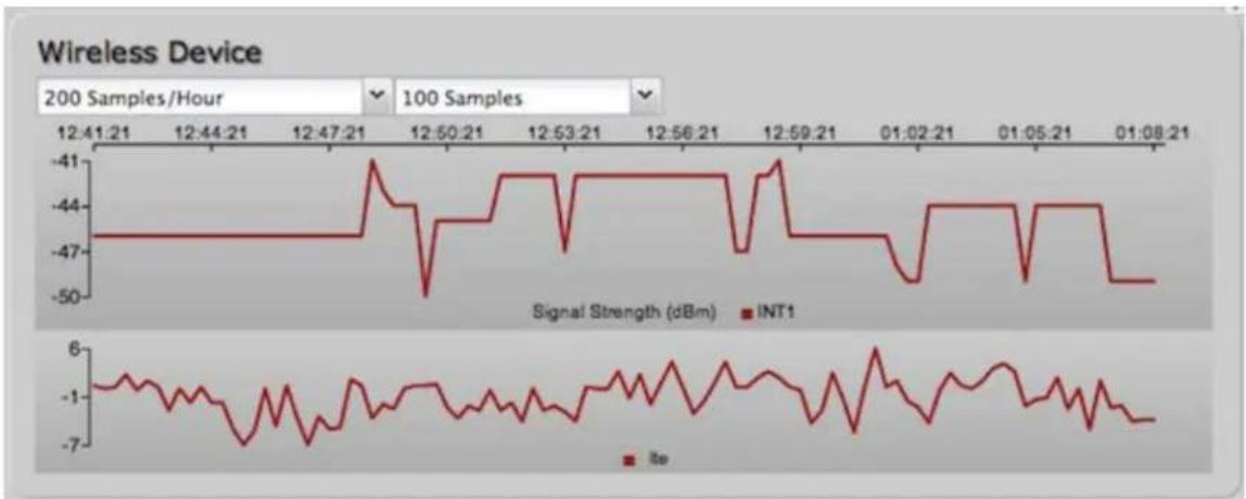
Data Usage: A measure of the amount of information that is currently being sent or received through the network. Sample rate and size can be adjusted from the dropdown boxes.
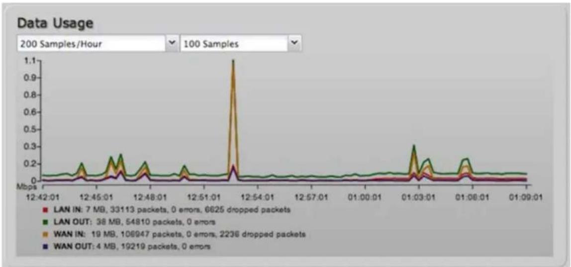
line
| Time | LAN IN | LAN OUT | WAN IN | WAN OUT | | ---------- | ------ | ------- | ------ | ------- | | 12:42:01 | 7 MB | 33113 | 19 MB | 4 MB | | 12:45:01 | 33113 | 54810 | 106947 | 19219 | | 12:48:01 | 54810 | 2236 | - | - | | 12:51:01 | - | - | - | - | | 12:54:01 | - | - | - | - | | 12:57:01 | - | - | - | - | | 01:00:01 | - | - | - | - | | 01:03:01 | - | - | - | - | | 01:06:01 | - | - | - | - | | 01:09:01 | - | - | - | - |Failover/Failback/Load Balance: An easy way to view current connective states of the devices plugged into the router as compared to the past. Sample rate and size can be adjusted from the dropdown boxes.
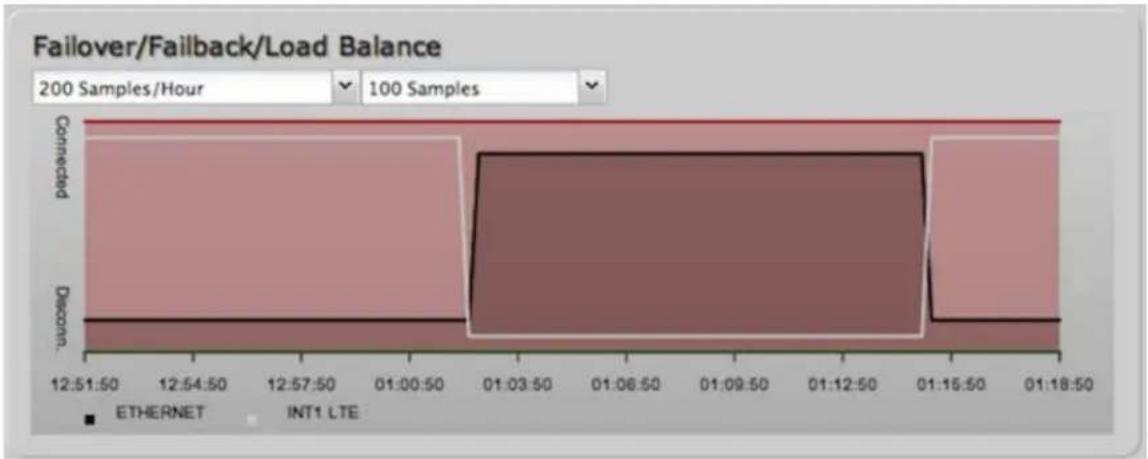
line
| Time | Connection | Discount | | ---------- | ---------- | -------- | | 12:51:50 | 200 Samples | 0 | | 12:54:50 | 200 Samples | 0 | | 12:57:50 | 200 Samples | 0 | | 01:00:50 | 200 Samples | 0 | | 01:03:50 | 200 Samples | 0 | | 01:06:50 | 200 Samples | 0 | | 01:09:50 | 200 Samples | 0 | | 01:12:50 | 200 Samples | 0 | | 01:15:50 | 200 Samples | 0 | | 01:18:50 | 200 Samples | 0 |System Logs
The router automatically logs (records) events of possible interest in its internal memory. If there is not enough internal memory for all events, logs of older events are deleted, but logs of the latest events are retained. The log options allow you to filter the router logs so you can easily find relevant messages. This router also has external Syslog Server support so you can send the log files to a computer on your network that is running a Syslog utility.
| Auto Update | Update | Clear log | Save Log | search filter... | Level |
| Time | Source | Level | Message | ||
| Thu Dec 13th 10:08:56 | wlan | INFO | Client e4:ce:8f:13:f3:bc WPA2 key negotiation completed | ||
| Thu Dec 13th 09:59:17 | WAN:2043 INFO | signal: 92% -> 100% | |||
| Thu Dec 13th 09:58:17 | WAN:2043 INFO | signal: 100% -> 92% | |||
| Thu Dec 13th 09:57:17 | WAN:2043 INFO | signal: 92% -> 100% | |||
| Thu Dec 13th 09:56:16 | WAN:2043 INFO | signal: 100% -> 92% | |||
| Thu Dec 13th 09:55:16 | WAN:2043 INFO | signal: unknown -> 100% | |||
| Thu Dec 13th 09:55:16 | WAN:2043 INFO | Plug event: ok | |||
| Thu Dec 13th 09:55:10 | kernel | INFO | usbcore: registered new interface driver cpusb5 | ||
| Thu Dec 13th 09:55:09 | kernel | INFO | sd 9:0:0:0: [sda] Attached SCSI removable disk | ||
| Thu Dec 13th 09:55:09 | kernel | INFO | scsi 9:0:0:0: Direct-Access Nokia Datacard CD-ROM 0001 PQ: 0 ANSI: 0 | ||
| Thu Dec 13th 09:55:08 | kernel | INFO | scsi9 : usb-storage 1-2.1:1.6 | ||
| Thu Dec 13th 09:55:08 | kernel | INFO | usb 1-2.1: new high speed USB device number 13 using rt3xxx-ehci | ||
| Thu Dec 13th | kernel | INFO | usb 1-2.1: USB disconnect, device number 12 | ||
Auto Update: The logs automatically refresh whenever the router creates a new message.
Update: Click to check for new router messages.
Clear Log: Clear the log file
Save Log: This will open a dialog in your browser that will allow you to save the router's log to your computer.
Search: Enter keywords to find specific events.
Level: Select/Deselect from the following levels to filter messages by priority.
• Critical
- Error
- Warning
- Info
NOTE: The logs are erased whenever the router is rebooted or loses power.
VPN Tunnels
View the status of configured VPN tunnels. Included information:
Name
- Connections
- Status
Protocols
- Transferred
Direction
• Time Online
• Control
To set up or edit a VPN tunnel, go to Internet → VPN Tunnels.
WiPipe QoS
View the breakdown of packets and bytes sent and received associated with each WiPipe QoS rule.
| WiPipe QoS is Enabled | ||
| Queue | Transmit (packets/bytes) | Receive (packets/bytes) |
| Default | 3197 / 319.23 KB | 4893 / 5.62 MB |
| limit upload | 0 / 0.00 bytes | 0 / 0.00 bytes |
To set up or edit a WiPipe QoS rule, go to Network Settings → WiPipe QoS.
Network Settings
The Network Settings section of the Administration Pages provides access to tools for controlling the LAN (Local Area Networks). The Network Settings tab has the following dropdown menu items:
Content Filtering
DHCP Server
DNS
- Firewall
• MAC Filter / Logging
- Routing
- Routing Protocols
• WiFi / Local Networks
• WiPipe QoS
Content Filtering
You have two main options for filtering content for local networks.
- WebFilter Rules: Create a list of websites that will be either disallowed or allowed. Customize the filter settings for each network and/or each MAC address. (These rules will not block HTTPS websites.)
- Cloud Based Filtering/Security: Allows several options for filtering and security using third-party services;
- Umbrella by OpenDNS
- Zscaler
Network WebFilter Rules
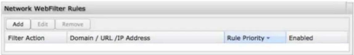
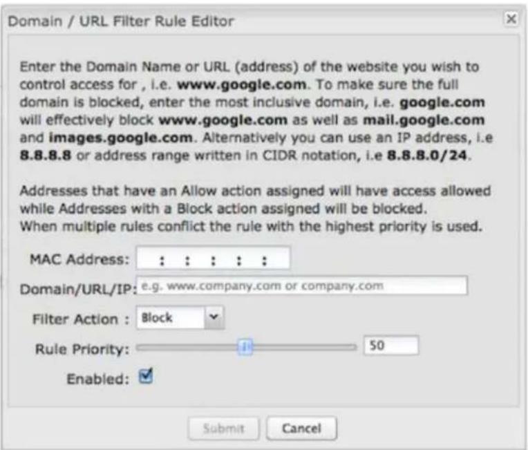
Network WebFilter Rules allow you to control access from your network to external domains or websites. Rules are assigned to a specific LAN network (or all networks). The highest priority rule will have precedence when there is a conflict. Addresses can be added by URL/Domain name or by IP address.
Exceptions to existing rules can be created by adding another rule with higher priority. For example, if access to espn.go.com is desired but go.com is blocked with a priority of 50, the addition of an "Allow" rule for espn.go.com with a priority of 51 or greater will allow access.
When creating rules keep in mind that some sites use multiple domains, so each domain may need a rule added to produce the desired behavior.
NOTE: Websites that use HTTPS will not be blocked by these rules. You will need to use OpenDNS to block HTTPS websites.
Click Add or Edit to open the Filter Rule Editor
- Assigned Network: Select either "All Networks" or one of your LAN networks from the dropdown list.
- Domain/URL/IP: Enter the Domain Name or URL (address) of the website you wish to control access for, e.g. www.google.com. To make sure the full domain is blocked, enter the most inclusive domain (e.g. google.com will effectively block www.google.com as well as maps.google.com and images.google.com). Alternatively you can use an IP address, e.g. 8.8.8.8, or address range written in CIDR notation, e.g. 8.8.8.0/24.
• Filter Action: Select Block or Allow.
Rule Priority: Higher number rules overrule lower number rules.
- Enabled: A rule can be enabled or disabled by selecting or deselecting the checkbox.
Click Submit to save your rule changes.
Default Network Filter Settings
| Default Network Filter Settings | ||
| Edit | ||
| Network Name | Default Action | Filter URLs by IP Address |
| Primary LAN | Allow Access | No |
| Guest LAN | Allow Access | No |
Use Default Network Filter Settings together with Network WebFilter Rules to control website access. All of your networks are set to allow website access by default. Select a network and click Edit to change the default filter settings.
Default Action: Select from the following dropdown options:
- Allow Access (default)
- Block Access
When a network is set to Allow Access, it will allow access to sites not specifically blocked in the WebFilter Rules.
When a network is set to Block Access, it will block access to sites not specifically allowed in the WebFilter Rules.
Filter URLs by IP Address: (Default: No) Changing this option to "Yes" will cause the router to perform a DNS lookup on URL entries, and the IP addresses will be appended to the appropriate block/allow list. This can have the side effect of being very strict; sites that are hosted across many domains may need every domain added to the list for full functionality.
MAC Address WebFilter Rules
MAC Address WebFilter Rules allow you to control access from a specific MAC address to external domains or websites.
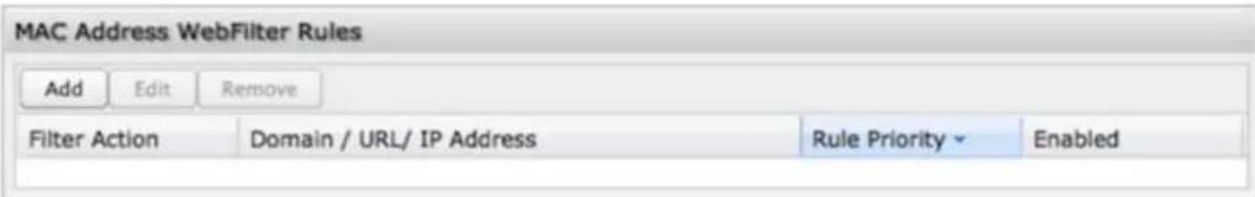
The settings for the MAC Address WebFilter Rules section match those for the Network WebFilter Rules, except that you must assign a MAC address instead of a
network to each rule.
See the Network WebFilter Rules section (above) for more configuration details.
MAC Address WebFilter Defaults
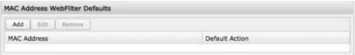
Use MAC Address WebFilter Defaults together with MAC Address WebFilter Rules to control website access for specific MAC addresses. By default, each MAC address is allowed website access. Click Add/Edit to change this setting for a MAC address.
Input the MAC address and default action you would like to apply to that MAC address.
Default Action: Select from the following dropdown options:
- Allow Access (default)
- Block Access
When a network is set to Allow Access, it will allow access to sites not specifically blocked in the WebFilter Rules. When a network is set to Block Access, it will block access to sites not specifically allowed in the WebFilter Rules.
Cloud Based Filtering/Security
Select a third-party Cloud Provider from the dropdown list.
- Umbrella by OpenDNS
- Zscaler
Umbrella by OpenDNS
Umbrella by OpenDNS is a cloud-based web filtering and security solution that protects you online by filtering websites. Go to http://www.oendns.com/business-security/ for information about Umbrella.
Enter your Umbrella account information in order to use these content filtering settings.
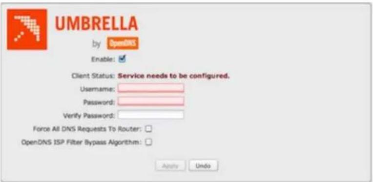
Force All DNS Requests To Router: Enabling this will redirect all DNS requests from LAN clients to the router's DNS server. This will allow the router even more control over IP Addresses even when the client might have their own DNS servers statically set.
OpenDNS ISP Filter Bypass Algorithm: It is possible that your Internet Service Provider (ISP) uses the port that OpenDNS is configured to access, port 53, which will prevent OpenDNS filtering. If OpenDNS does not appear to be working correctly, enabling this will attempt to bypass those ports when using an OpenDNS content filtering level.
Zscaler
Zscaler is a cloud based web filtering and security provider that offers several plan options. Depending on your Zscaler implementation, this could include:
• Global Cloud Platform
• Real-Time Reporting
• Behavioral Analysis
- URL Filtering
• Advanced Threat Protection
• Inline Anti Virus & Anti-Spyware
- Web 2.0 Control
• Data Loss Prevention
• Bandwidth Management
- Web Access Control
• And more...
NOTE: Zscaler requires a feature license. Go to System Settings → Feature Licenses to enable this feature.
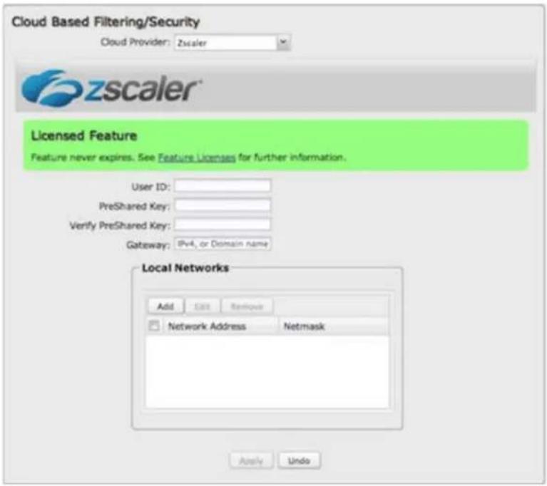
Enter your Zscaler account information to enable these settings. Input local network information (Network Address and Netmask) to assign your Zscaler implementation to one or more local network(s).
DHCP Server
DHCP stands for Dynamic Host Configuration Protocol. The built-in DHCP server automatically assigns IP addresses to the computers and other devices on each local area network (LAN). In this section you can view a list of assigned IP addresses and reserve IP addresses for particular devices.
| Active Leases | |||||
| Reserve | |||||
| Hostname | IP Addr | Hardware Addr | Client ID | Expiration | |
| drush-le6500 | 192.168.0.86 | 00:26:5e:4d:0c:7c | 01:00:26:5e:4d:0... | 11 hours, 25 mins | |
| jcramer-osx | 192.168.0.87 | e4:ce:8f:13:f3:bc | 01:e4:ce:8f:13:f3:... | 11 hours, 25 mins | |
Active Leases: A list of devices that have been provided DHCP leases. The DHCP server automatically assigns these leases. This list will not include any devices that have static IP addresses on the network. Select a device and click Reserve to add the device and its IP address to the list of Reservations.
Reservations: This is a list of devices with reserved IP addresses. This reservation is almost the same as when a device has a static IP address except that the device must still request an IP address from the router. The router will provide the device the same IP address every time. DHCP reservations are helpful for server computers on the local network that are hosting applications such as Web and FTP. Servers on your network should either use a static IP address or a reservation.
While you have the option to manually input the information to reserve an IP address (Hostname, Hardware Addr, IP Addr), it is much simpler to select a device under the Active Leases section and click "Reserve." The selected device's information will automatically be added under Reservations.
DNS
DNS, or Domain Name System, is a naming system that translates between domain names (www.cradlepoint.com, for example) and Internet IP addresses (206.207.82.197). A DNS server acts as an Internet phone book, translating between names that make sense to people and the more complex numerical identifiers. The DNS page for the device has these distinct functions:
- DNS Settings: By default your router is set to automatically acquire DNS servers through your Internet provider (Automatic). DNS Settings allows you to specify DNS servers of your choosing instead (Static).
- Dynamic DNS Configuration: Allows you to host a server (Web, FTP, etc.) using a domain name that you have purchased (www.example.com) with your dynamically assigned IP address.
- Known Hosts Configuration: Allows you to map a name (printer, scanner, laptop, etc.) to an IP address of a device on the network.
DNS Settings
You have the option to choose specific DNS servers for your network instead of using the DNS servers assigned by your Internet provider. The default DNS servers are usually adequate. You may want to assign DNS servers if the default DNS servers are performing poorly, if you want WiFi clients to access DNS servers that you use for customized addressing, or if you have a local DNS server on your network.
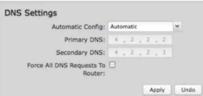
Automatic Config: Automatic or Static (default: Automatic). Switching to "Static" enables you to set specific DNS servers in the Primary DNS and Secondary DNS fields.
Primary DNS and Secondary DNS: If you choose to specify your DNS servers, then enter the IP addresses of the servers you want as your primary and secondary DNS servers in these fields. The DNS server settings will be pre-populated with public DNS server IP addresses. You can override the IP address with any other DNS server IP address of your choice. For example, Google Public DNS servers have the IP addresses 8.8.8.8 and 8.8.4.4 while 4.2.2.2 and 4.2.2.3 are servers from Level 3 Communications.
Force All DNS Requests To Router: Enabling this will redirect all DNS requests from LAN clients to the router's DNS server. This will allow the router even more control over IP addresses even when clients have their own DNS servers statically set.
Dynamic DNS Configuration
The Dynamic DNS feature allows you to host a server (Web, FTP, etc.) using a domain name that you have purchased (www.youname.com) with your dynamically assigned IP address. Most broadband Internet Service Providers assign dynamic (changing) IP addresses. When you use a Dynamic DNS service provider, you can enter your host name to connect to your server, no matter what your IP address is.
- Enable Dynamic DNS: Enable this option only if you have purchased your own domain name and registered with a Dynamic DNS service provider.
• Server Type. Select a dynamic DNS service provider from the dropdown list:
DynDNS
DNS O Matic
- ChangelP
NO-IP
- Custom Server (DynDNS clone)
- Custom Server Address. Only available if you select Custom Server from the Server Address dropdown list. Enter your custom DynDNS clone server address here. For example: www.mydyndns.org.
- Use HTTPS: Use the more secure HTTPS protocol. This is recommended, but could be disabled if not compatible with the server.
- Host name: Enter your host name, fully qualified. For example: myhost.mydomain.net.
- User name: Enter the user name or key provided by the dynamic DNS service provider. If the dynamic DNS provider supplies only a key, enter that key for both the User name and Password fields.
- Password: Enter the password or key provided by the dynamic DNS service provider.
Advanced Dynamic DNS Settings
Update period (hours):
Override External IP: The external IP is usually configured automatically during connection. However, in situations where the unit is within a private network behind a firewall or router, the network's external IP address will have to be manually configured in this field.
You may find out what your external IP address is by going to http://myip.dnsomatic.com/ in a web browser.
Known Hosts Configuration
The Known Hosts Configuration feature allows you to map a name (printer, scanner, laptop, etc.) to an IP address of a device on the network. This assigns a new hostname that can be used to conveniently identify a device within the network, such as an office printer.
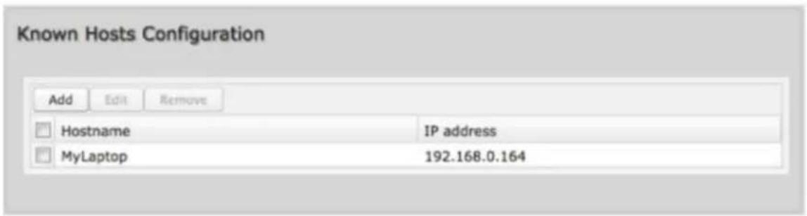
Click Add to name a device in your network.
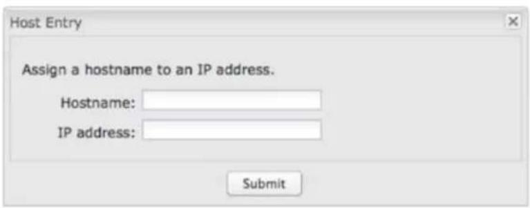
Fill in the following fields:
- Hostname: Choose a name that is meaningful to you. No spaces are allowed in this field.
• IP address: The address of the device within your network.
EXAMPLE: a personal laptop with IP address 192.168.0.164 could be assigned the name "MyLaptop".
Since the assigned name is mapped to an IP address, the device's IP address should not change. To ensure that the device keeps the same IP address, go to Network Settings → DHCP Server and reserve the IP address for the device by selecting the device in the Active Leases list and clicking "Reserve".
Firewall
The router automatically provides a firewall. Unless you configure the router to the contrary, the router does not respond to unsolicited incoming requests on any port, thereby making your LAN invisible to cyber attackers.
However, some network applications cannot run with a tight firewall. Those applications need to selectively open ports in the firewall to function correctly. The options on this page control ways of opening the firewall to address the needs of specific types of applications.
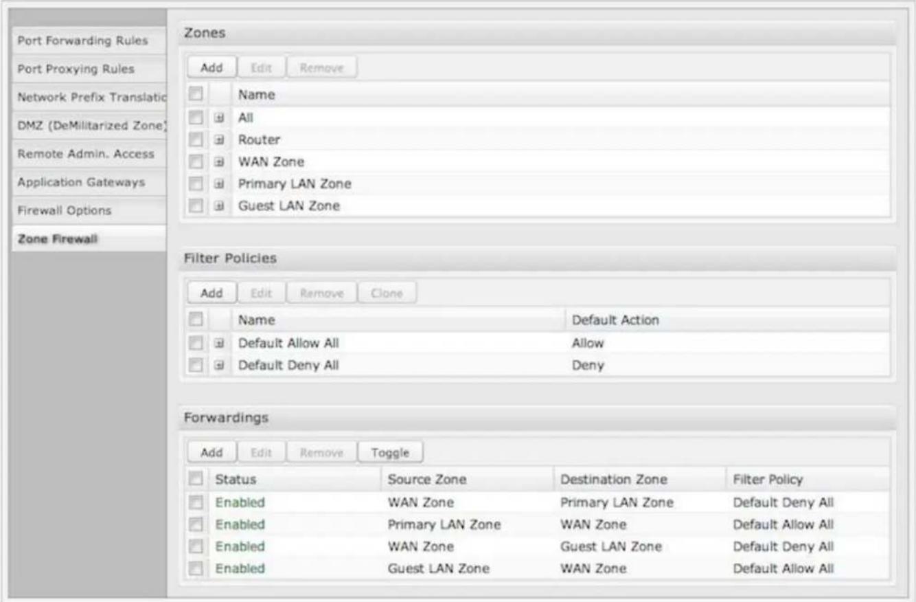
Select from the following tabs to edit your firewall configuration:
• Port Forwarding Rules
- Port Proxying Rules
• Network Prefix Translation
• DMZ (DeMilitarized Zone)
- Remote Admin. Access
• Application Gateways
- Firewall Options
- Zone Firewall
Port Forwarding Rules
A port forwarding rule allows traffic from the Internet to reach a computer on the inside of your network. For example, a port forwarding rule might be used to run a Web server.
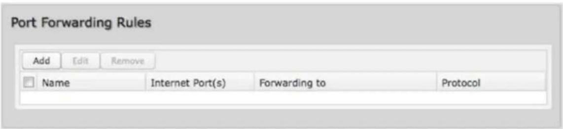
NOTE: Exercise caution when adding new rules as they impact the security of your network.
Click Add to create a new port forwarding rule, or select an existing rule and click Edit.
Add/Edit Port Forwarding Rule
• Name: Name your rule.
- Enabled: Toggle whether your rule is enabled. Selected by default.
- Use Port Range: Changes the selection options to allow you to input a range of ports (if desired).
- Internet Port(s): The port number(s) as you want it defined on the Internet. Typically these will be the same as the local port numbers, but they do not have to be. These numbers will be mapped to the local port numbers.
- Local Computer: Select the IP address of an attached device from the dropdown menu, or manually input the IP address of a device.
- Local Port(s): The port number(s) that corresponds to the service (Web server, FTP, etc) on a local computer or device. For example, you might input "80" in the Local Port(s) field to open a port for a Web server on a computer within your network. The Internet Port(s) field could then also be 80, or you could choose another port number that will be used across the Internet to access your Web server. If you choose a number other than 80 for the Internet Port, connections to that number will be mapped to 80 – and therefore the Web server – within your network.
- Protocol: Select from the following options in the dropdown menu:
TCP
- UDP
- TCP & UDP
- Click Submit to save your completed port forwarding rule.
Port Proxying Rules
A port proxy rule allows traffic from the local LAN to be redirected to a specific computer/IP address on the Internet.
Click Add to create a new port proxying rule, or select an existing rule and click Edit.
Add/Edit Port Proxying Rule
• Name: Name your rule.
- Enabled: Toggle whether your rule is enabled. Selected by default.
- Use Port Range: Check this box to create a rule which proxies a contiguous range of ports instead of a single port. The remote port(s) will require the same number of contiguous ports.
- Local Port(s): Specify the IP port(s) on the LAN to proxy to a remote computer.
- Remote Computer: Specify the remote computer to receive proxied traffic.
- Remote Port(s): Specify the IP port (first if a range) on the remote computer to receive proxy traffic.
- Protocol: Select the IP protocol traffic to proxy from the following options in the dropdown menu:
- TCP
- UDP
- TCP & UDP
- Click Submit to save your completed port proxying rule.
Network Prefix Translation
Network Prefix Translation is used in IPv6 networks to translate one IPv6 prefix to another. IPv6 prefix translation is an experimental specification (RFC 6296) trying to achieve address independence similar to NAT in IPv4. Unlike NAT, however, NPT is stateless and preserves the IPv6 principle that each device has a routable public address. But it still breaks any protocol embedding IPv6 addresses (e.g. IPsec) and is generally not recommended for use by the IETF. NPT can help to keep internal network ranges consistent across various IPv6 providers, but it cannot be used effectively in all situations.
The primary purpose for CradlePoint's NPT implementation is for failover/failback and load balancing setups. LAN clients can potentially retain the original IPv6 lease information and may experience a more seamless transition when WAN connectivity changes than if not utilizing NPT.

Mode
- None – No translation is performed
- Load Balance Only – (Default) Only translate networks when actively load balancing
- First – Use the first IPv6 prefix found
• Static – Always use a static IPv6 translation (input the prefix here)
Transitioning from short prefix to a longer prefix (such as from /48 to /64) is not without problems, as some of the LANs may lose IPv6 connectivity.
DMZ (DeMilitarized Zone)
A DMZ host is effectively not firewalled in the sense that any computer on the Internet may attempt to remotely access network services at the DMZ IP address. Typical uses involve running a public Web server or sharing files.
Input the IP Address of a single device in your network to create a DeMilitarized Zone for that device. To ensure that the IP address of the selected device remains consistent, go to the "Reservations" section under Network Settings → DHCP Server and reserve the IP address for the device.
Use caution when enabling the DMZ feature, as it can threaten the security of your network. Only use DMZ as a last resort.
Remote Admin. Access
Enable Remote Administration Access Control: Selecting this option allows you to make remote administration tools available to only the specified IP addresses. Access from all other IP addresses will be blocked. This option only filters IP addresses: you must enable Remote Management separately (System Settings → Administration).
The services affected by this include remote HTTP, HTTPS, SNMP, and SSH configuration tools. This does not impact LAN-based administration, i.e., devices within your network still have administration access. The individual remote administration services can be enabled under System Settings → Administration: select the Remote Management tab.
Add/Edit Allowed Remote Access Addresses
IP Address: The IP address that will be allowed to access administrative services through the WAN
Netmask (Optional): The netmask allows you to specify what IP address sets will be allowed access. If this field is left empty a netmask of 255.255.255.255 is used, which means that only the single specified IP address has remote administration access.
Application Gateways
Enabling an application gateway makes pinholes through the firewall. This may be required for some applications to function, or for an application to improve functionality or add features.
Exercise caution in enabling application gateways as they impact the security of your network.
Application Gateways
Enabling an application gateway makes pinholes thru the firewall. This may be required for some applications to function, or for an application to improve functionality or add features.
Exercise caution in enabling application gateways as they impact the security of your network.

Enable any of the following types of application gateways:
- PPTP: For virtual private network access using Point-to-Point Tunneling Protocol. This is enabled by default.
• SIP: For VoIP (voice over IP) using Session Initiation Protocol.
• TFTP: Enables file transfer using Trivial File Transfer Protocol, - FTP: To allow normal mode when using File Transfer Protocol. This is not needed for passive mode. This is enabled by default.
- IRC: For Direct Client to Client (DCO) transfer when using Internet Relay Chat. You may wish to forward TCP port 113 for incoming identd (RFC 1413) requests.
Firewall Options
Firewall Options


Anti-Spoof: Anti-Spoof checks help protect against malicious users taking the source address in packets they transmit in order to either hide themselves or to impersonate someone else. Once the user has spoofed their address they can launch a network attack without revealing the true source of the attack or attempt to gain access to network services that are restricted to certain addresses.
Log Web Access: Enable this option to create a syslog record of web (IP port 80) access. Each entry will contain the IP address of the server and the client. Note that this may create a lot of log entries, especially on a busy network. Sending the system log to a syslog server is recommended.
To view the logs, go to Status → System Logs. For configuration options, including syslog server setup, go to System Settings → Administration and select the System Logging tab.
Zone Firewall
A zone is a group of network interfaces. By default, all interfaces within a zone are allowed to initialize network communication with each other, but any network traffic initialized outside of a zone to the interfaces within the zone is denied. Forwardings are used to allow traffic to traverse zones. Filter Policies are used to define how traffic passing through a zone forwarding is filtered. Zones can be added, edited, or removed (except for the All and Router zone).
Zones
Create, edit, and remove zones (i.e., groups of network interfaces). Once you have defined zones, add rules to the Filter Policies and Forwardings sections to define what traffic is allowed between zones.
- The All zone is a special zone used to support legacy firewall configurations. This zone cannot be removed and is reserved for forward-migration of IP Filter Rules from previous firmware versions. The All zone matches any traffic handled by the router. User defined zones are preferred.
- The Router zone is a special zone used to filler traffic initialized from the router (e.g., Enterprise Cloud Manager connection) or destined to the router (e.g., SNMP) as part of a router services setup. (Set up This zone cannot be removed and can only be altered by router services.
Click Add to create a new zone.
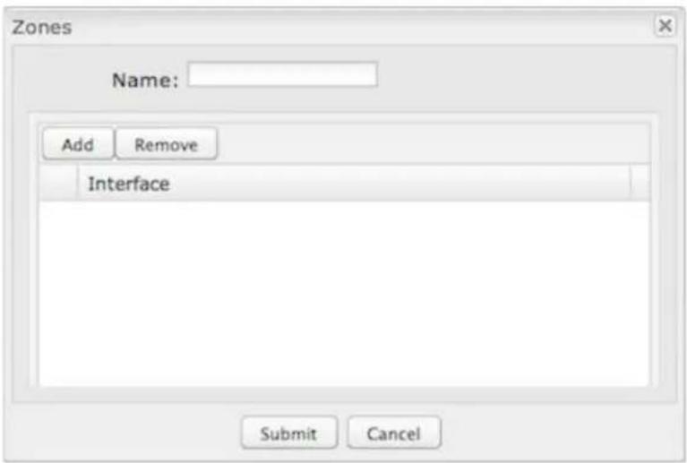
Choose a Name meaningful to you and then click on the Add button to reveal options for attaching interfaces (WAN, LAN, or GRE) to this zone.
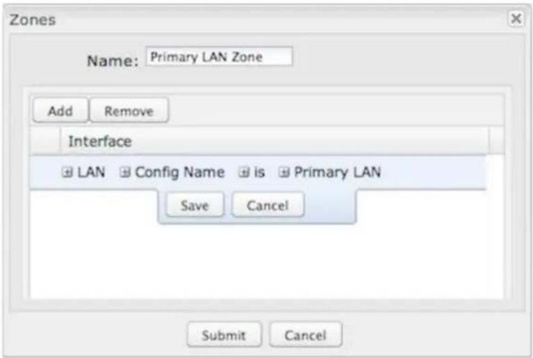
LAN and GRE Interfaces
Attach LAN and GRE interfaces to a zone by selecting the Config Name for those interfaces. For LANs, these names are defined in Network Settings → WiFi / Local Networks; for GRE tunnels, these names are defined in Internet → GRE Tunnels.
| Sample zone interface assignments: LAN & GRE | ||
| LAN Config Name is Primary LAN | ||
| LAN Config Name isn't Guest LAN | ||
| GRE Config Name is office_tunnel | ||
The third field defaults to "is," but you can also select "is not," "starts with," "contains," or "ends with" to define the zone.
WAN Interfaces
Attaching WAN interfaces to a zone includes many more options. Select "WAN" in the first field, and then select from each of the following fields to create a statement that defines which WAN interfaces to attach to this zone.
Field 2: Choose one of the following:
- Port – Select by the physical port on the router (e.g., "Modern 1").
- Manufacturer – Select by the modem manufacturer (e.g., "CradlePoint Inc.).
• Model – Select according to the specific model of modem. - Type – Select by type of Internet source (Ethernet, LTE, Modem, Wireless as WAN, WiMAX).
- Serial Number – Select a 3G or LTE modem by the serial number.
• MAC Address – Select from a dropdown list of attached devices. - Unique ID – Select by ID. This is generated by the router and displayed when the device is connected to the router.
Field 3: Select "is," "is not," "starts with," "contains," or "ends with" to create your condition.
Field 4: If the desired values are available, select from the dropdown list. You may need to manually input the value.
| Sample zone interface assignments: WAN | ||
| WAN Type is Ethernet | ||
| WAN Port isn't Modem 1 | ||
Filter Policies
A Filter Policy is a one-way filter applied to initialized network traffic flowing from one zone to another. A Filter Policy needs to be assigned to a Forwarding for it to take effect. Filter Policies can either be Added, Edited, Removed, or Cloned. Cloning a Policy will copy the entire policy. The name of the cloned policy will include the name plus "Clone".
| Filter Policies | ||||
| Add | Edit | Remove | Clone | |
| Name | Default Action | |||
| Default Allow All | Allow | |||
| Default Deny All | Deny | |||
- Default Allow All is a preconfigured policy to allow all traffic initialized from one zone to flow to another zone. The state of the connection is tracked to allow responses to traverse the zones back to the source. LAN to WAN forwardings use this policy by default. The policy can be removed or altered to filter the traffic flow,
- Default Deny All is a preconfigured policy to deny all traffic initialized from one zone to be blocked to another zone. WAN to LAN forwardings use this policy by default. The policy can be removed or altered to filter the traffic flow.
Click Add to create a new filter policy, or select an existing policy and click Edit to open the filter policy editor.
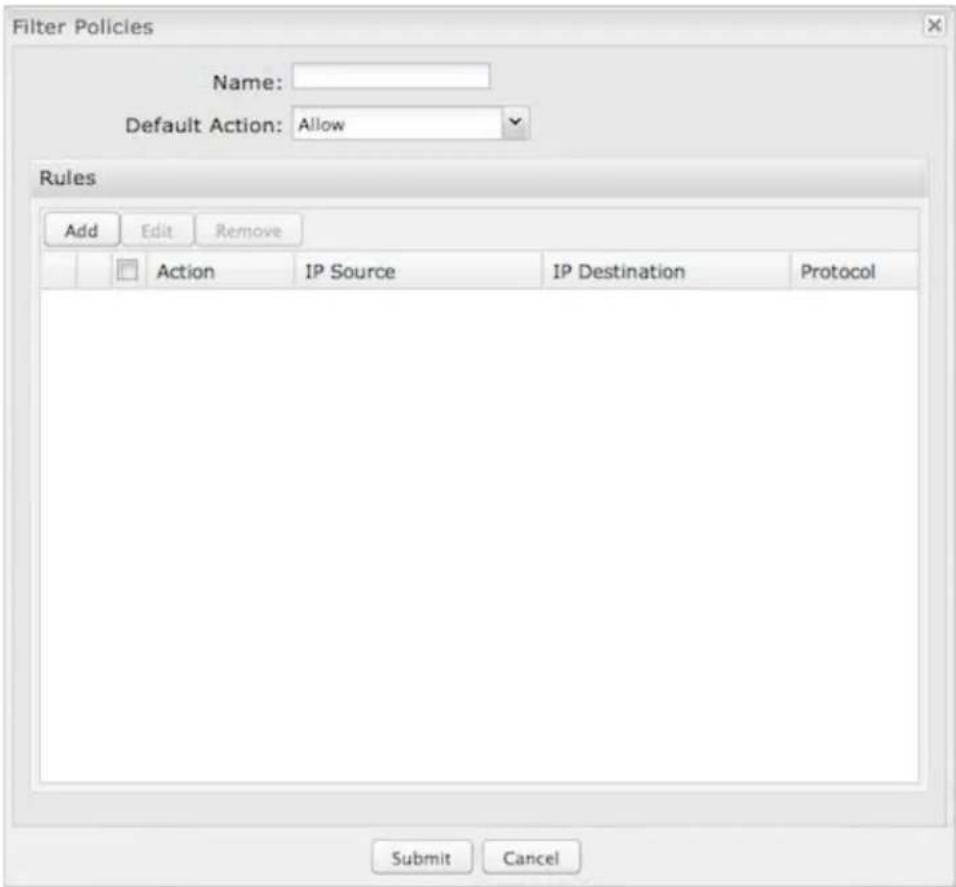
• Name: Create a name meaningful to you.
- Default Action: Choose either Allow or Deny This is the action taken by the firewall if none of the filter policy rules match the traffic being filtered.
Click Add to create a new rule for this filter policy.
Rule Editor
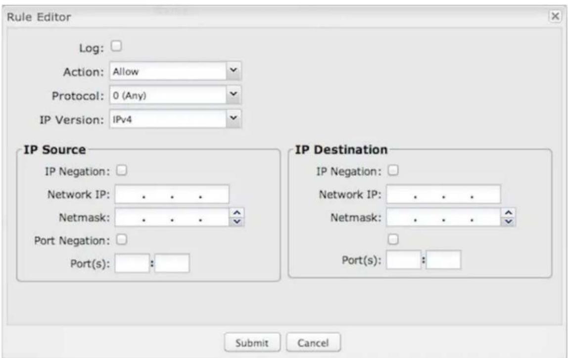
- Log: When checked each packet matching this filter rule will be logged in the System Logs.
• Action: "Allow" or "Deny". - Protocol: Any, ICMPv4, TCP, UDP, GRE, ESP, ICMPv6, or SCTP.
• IP Version: Any, IPv4, or IPv6.
IP Source / IP Destination
• IP Negation: Match on any IP address that is NOT in the specified IP network range.
• Network IP: Optional field to specify a matching network IP address for this rule to match against.
- Netmask: Use this to define a subnet size this rule will match against.
• Port Negation: Match on any port that is NOT in the specified port range.
- Port(s): Use for a single port or a range of ports. Fill in the left side for a single port.
Use Network IP, Netmask, and Port(s) to specify the ports and addresses for which the rule applies. You can specify a range of ports or a single port. Similarly, the netmask can be used to define either a range of addresses (i.e. 255.255.255.0) or a single address (255.255.255.255).
If you leave these values blank, then all IP addresses and ports will be included. IP Source and IP Destination options can be used to differentiate between the directions that packets go. You could permit packets to come from particular IP addresses but then not allow packets to return to those addresses.
Forwardings
Forwardings define how Filter Policies affect traffic flowing between zones in one direction. Simply select the Source Zone, Destination Zone, and Filter Policy to define a Forwarding. Forwardings can either be Added, Edited, Removed, or Toggled. Toggling a Forwarding will either enable or disable the Forwarding.
Forwardings
| Add Edit Remove Toggle | ||||
| Status | Source Zone | Destination Zone | Filter Policy | |
| Enabled | WAN Zone | Primary LAN Zone | Default Deny All | |
| Enabled | Primary LAN Zone | WAN Zone | Default Allow All | |
| Enabled | WAN Zone | Guest LAN Zone | Default Deny All | |
| Enabled | Guest LAN Zone | WAN Zone | Default Allow All | |
Click Add to create a new Forwarding, or select an existing Forwarding and click Edit to open the Forwardings editor.
- Enabled: Selected by default. Click to deselect.
• Source Zone: Select from the dropdown list of your defined zones. - Destination Zone: Select from the dropdown list of your defined zones.
• Filter Policy: Select from the dropdown list of your filter policies.
MAC Filter / Logging
A MAC (Media Access Control) address is a unique identifier for a computer or other device. This page allows you to manage clients by MAC address. You can filter clients by MAC addresses and/or keep a log of devices connected to your router.
Filter Configuration
The MAC Filter allows you to create a list of devices that have either exclusive access (whitelist) or no access (blacklist) to your local network.
Enabled: Click to allow MAC Filter options.
Whitelist: Select either "Whitelist" or "Blacklist" from a dropdown menu. In "Whitelist" mode, the router will restrict LAN access to all computers except those contained in the "MAC Filter List" panel. In "Blacklist" mode, listed devices are completely blocked from local network access.
MAC Filter List (Whitelist or Blacklist): Add devices to either your whitelist or blacklist simply by inputting each device's MAC address.
NOTE: Use caution when using the MAC Filter to avoid accidentally blocking yourself from accessing the router.
MAC Logging Configuration
Enable MAC Logging: Enabling MAC Logging will cause the router to log MAC addresses that are connected to the router. MAC addresses that you do not want to have logged (addresses that you expect to be connected) should be added to the "Ignored MAC Addresses" list.
You can configure the router to send an alert if a connected device has a MAC address that the router doesn't recognize. Go to System Settings → Device Alerts to set up these email alerts.
Ignored MAC Addresses: This is the list of MAC addresses that will not produce an alert or a log entry when they are connected to the router. These should be MAC addresses that you expect to be connected to the router. To add MAC addresses to this list, simply select devices shown in the MAC Address Log and click "Ignore." You can also add addresses manually.
MAC Address Log: This shows the last 64 MAC addresses that have connected to the router, as well as which interface was used to connect. The time/date that is logged is the time of the first connection. The page may need to be refreshed to show the most recent log entries.
Double-clicking on entries from this list will add them to the Ignored MAC Addresses list.
Routing
Add a new static route to the IP routing table or edit/remove an existing route.
Static routes are used in networks with more than one layer, such as when there is a network within a network so that packet destinations are hidden behind an additional router. Adding a static route is a way of telling the router about an additional step that packets will need to take to reach their destination.
| Add | Edit | Remove | |
| IP/Network Address | Netmask | Gateway | |
| ✓ | 192.168.0.1 | 255.255.255.0 | 172.22.22.1 |
Click Add to create a new static route.
IP Version: Select IPv4 or IPv6. Depending on your selection, you have different options for defining the address range.
IP/Network Address or IPv6 Address: The IP address of the target network or host. The IPv6 address field includes CIDR notation to declare a range of addresses.
Netmask: The Netmask, along with the IPv4 address, defines the network the computer belongs to and which other IP addresses the computer can see in the same LAN. An IP address of 192.168.0.1 along with a Netmask of 255.255.255.0 defines a network with 256 available IP addresses from 192.168.0.0 to 192.168.0.255.
NOTE: 255.255.255.255 is used to signify only the host that was entered in the IP/Network Address field.
Gateway or IPv6 Gateway: Specifies the next hop to be taken if this route is used. A gateway of 0.0.0.0 implies there is no next hop, and the IP address matched is directly connected to the router on the interface specified: LAN or WAN.
Device: Select the network interface from the dropdown menu (e.g. ethernet-war). You can use this instead of defining the IP address, especially in cases when the IP address is changing.
Metric: Set the numerical priority of the route. Lower numbers have higher priority.
Allow Network Access: (Default: Deselected.) Some static routes will need an IP Filter Rule via the Firewall to allow packets through the route without being blocked. Selecting this option automatically creates this IP Filter Rule. If the IP/Network Address falls outside the LAN IP range, you probably need to select this option.
Distribute: Allow this static route to be distributed via a routing protocol (Network Settings → Routing Protocols).
Routing Protocols
NOTE: Routing Protocols require a feature license. Go to System Settings → Feature Licenses to enable these features.
A routing protocol is a protocol that specifies how routers communicate with each other, disseminating information that enables them to select routes between any two nodes on a computer network. Routing algorithms choose the route. Each router has a prior knowledge only of networks attached to it directly. A routing protocol shares this information first among immediate neighbors, and then throughout the network. This way, routers gain knowledge of the topology of the network.
Choose from the following labs to configure routing protocols:
• BGP Routing
- OSPF Routing
- RIP Routing
- RIPNG Routing
- Route Maps and Filters
BGP Routing
The latest version of BGP (Border Gateway Protocol) is version 4. BGP-4 is one of the Exterior Gateway Protocols and de facto standard of Inter Domain routing protocol. BGP-4 is described in RFC1771, A Border Gateway Protocol 4 (BGP-4). BGP is a distance vector routing protocol, and the AS-Path framework provides distance vector metric and loop detection to BGP. RFC1930.
BGP Editor
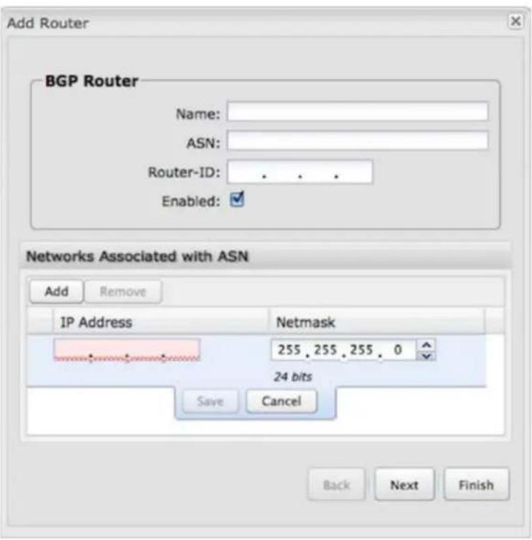
• Name: Unique name of the policy.
• ASN: The AS (Autonomous System) number is one of the essential elements of BGP.
- Router-ID. This sets the router-ID of the BGP process. The router-ID may be an IP address of the router, but need not be - it can be any arbitrary 32-bit number. However it MUST be unique within the entire BGP domain to the BGP speaker: bad things will happen if multiple BGP speakers are configured with the
same router-ID.
- Enabled: Click to enable/disable the policy. (Default: enabled.)
Networks Associated with ASN or IPv6 Networks Associated with ASN: To configure a BGP router, you need an AS number. An AS number is an identification of autonomous system. BGP protocol uses the AS number for detecting whether the BGP connection is internal one or external one. Use the IPv4 address and netmask or IPv6 address with a CIDR notation prefix length to define the address range.
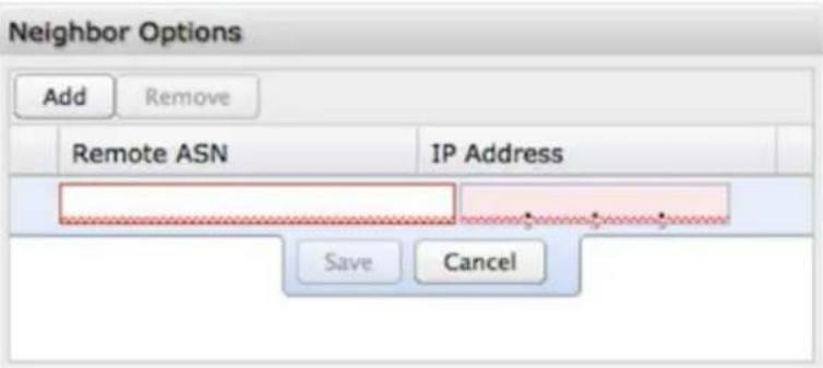
Neighbor Options or IPv6 Neighbor Options: Creates a new neighbor identified by remote ASN and IP address.

Redistribute Routes: Redistribute routes of the specified protocol or kind into BGP, with the metric type and metric set if specified, filtering the routes using the given route map if specified. Redistributed routes may also be filtered with distribute lists.
- Type: The type is the source of the route. Select from: Main, Connected, Static, RIP, and OSPF.
• Metric: Numerical priority of the route. - Route Map: Route maps provide a means to filter and/or apply actions to routes, allowing policies to be applied to routes.
OSPF Routing
OSPF (Open Shortest Path First) version 2 is a routing protocol described in RFC2328, OSPF Version 2. OSPF is an IGP (Interior Gateway Protocol). Compared with RIP, OSPF can provide more scalable network support and faster convergence times. OSPF is widely used in large networks such as ISP (Internet Service Provider) backbone and enterprise networks.
OSPF Areas
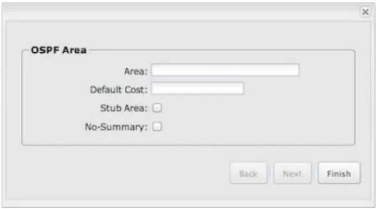
• Area: Areas are identified by an ID.
- Default Cost: Set the cost of default-summary LSAs announced to stubby areas.
- Stub Area: Configure area to be stub area.
• No-Summary: Prevents ABR from injecting inter-area summaries into the specified stub area
OSPF Editor
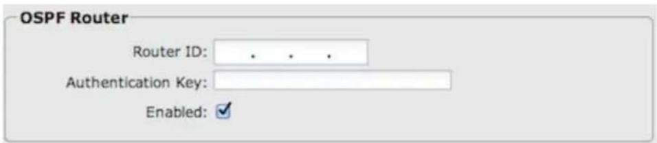
- Router ID: This sets the router-ID of the OSPF process. The router-ID may be an IP address of the router, but need not be – it can be any arbitrary 32-bit number. However it MUST be unique within the entire OSPF domain to the OSPF speaker – bad things will happen if multiple OSPF speakers are configured with the same router-ID.
- Authentication Key: Set OSPF authentication key to a simple password. After setting authentication key, all OSPF packets are authenticated. The authentication key has a maximum length of eight characters.
- Enabled: Click to enable/disable the policy. (Default: enabled.)
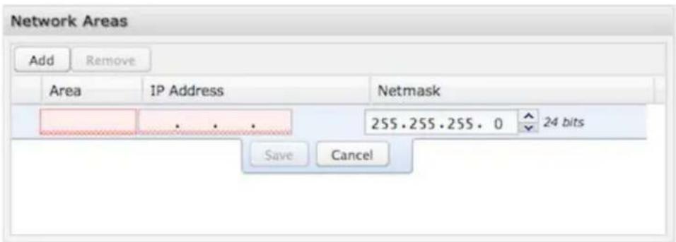
Network Areas: Areas are identified by an ID number. Use the IP address and netmask fields to associate a network with this policy.
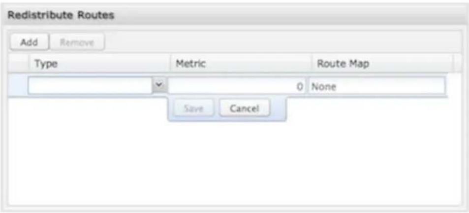
Redistribute Routes: Redistribute routes of the specified protocol or kind into BGP, with the metric type and metric set (if specified), filtering the routes using the given route map (if specified). Redistributed routes may also be filtered with distribute lists.
- Type: The type is the source of the route. Select from: Main, Connected, Static, RIP, OSPF.
• Metric: Numerical priority of the route. - Route Map: Route maps provide a means to filter and/or apply actions to routes, allowing policies to be applied to routes.
RIP Routing
RIP (Routing Information Protocol) is a widely deployed interior gateway protocol. RIP is a distance-vector protocol based on the Bellman-Ford algorithms. As a distance-vector protocol, RIP sends updates from one router to its neighbors periodically, allowing the convergence to a known topology. In each update, the distance to any given network will be broadcast to its neighboring router. The router supports RIP version 2 as described in RFC2453 and RIP version 1 as described in RFC1058.
RIP Editor
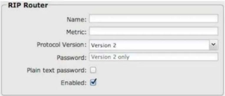
• Name: Unique name of the policy.
- Metric: RIP metric is a value for distance for the network. Usually RIP increments the metric when the network information is received. The metric for redistributed routes is set to 1.
- Protocol Version: RIP can be configured to send either Version 1 or Version 2 packets. The default is to send RIPv2 while accepting both RIPv1 and RIPv2 (and replying with packets of the appropriate version for REQUESTS / triggered updates).
- Password: RIPv2 allows packets to be authenticated via either an insecure plain text password, included with the packet, or a more secure MD5 based HMAC (keyed-Hashing for Message Authentication). RIPv1 cannot be authenticated at all, so when authentication is configured RIP will discard routing updates received via RIPv1 packets.
- Plain text password: Select to use a plain text password instead of an MD5 HMAC. A plain text password is insecure!
- Enabled: Click to enable/disable the policy. (Default: enabled.)
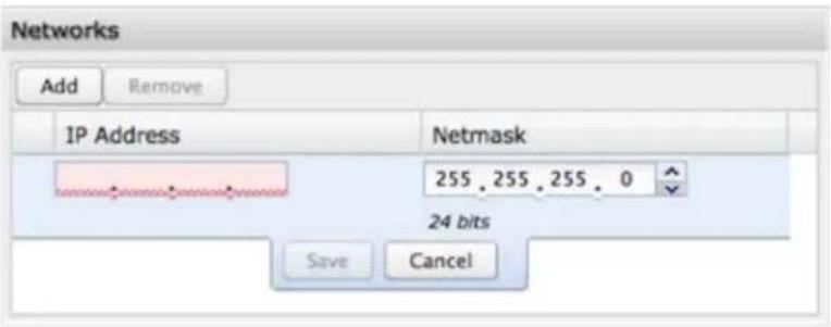
Networks: Set the RIP-enabled interfaces by network. RIP is enabled on the interfaces that have addresses within the network range.
Neighbors: When a neighbor doesn't understand multicast, this command is used to specify neighbors. In some cases, not all routers will be able to understand multicasting, where packets are sent to a network or a group of addresses. In a situation where a neighbor cannot process multicast packets, it is necessary to establish a direct link between routers. The neighbor command allows the network administrator to specify a router as a RIP neighbor. The no neighbor a.b.c.d command will disable the RIP neighbor. Assign a neighbor by inputting an IP address.
Redistribute Routes: Redistribute routes of the specified protocol or kind into RIP, with the metric type and metric set (if specified), filtering the routes using the given route map (if specified). Redistributed routes may also be filtered with distribute lists.
- Type: The type is the source of the route. Select from: Main, Connected, Static, OSPF, BGP.
- Metric: RIP metric is a value for distance for the network. Usually RIP increments the metric when the network information is received. The metric for redistributed routes is set to 1.
- Route Map: Route maps provide a means to filter and/or apply actions to routes, allowing policies to be applied to routes.
RIPNG Routing
RIPng (RIP next generation) extends RIPv2 to support IPv6. See RIPng on Wikipedia and RFC 2080 for details.
RIPNG Editor
• Name: Unique name of the policy.
- Metric: RIPng metric is a value for distance for the network. Usually the RIP service increments the metric when the network information is received. The metric for redistributed routes is set to 1.
- Enabled: Click to enable/disable the policy. (Default: enabled.)
Networks: Set the RIPng enabled interfaces by network using IPv6 addresses. RIPng is enabled on the interfaces that have addresses within the network range.
Routes: Set RIPng static routing announcement of specified network address.
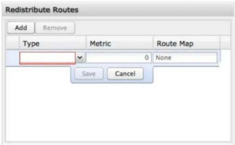
Redistribute Routes: Redistribute routes of the specified protocol or kind into RIPng, with the metric type and metric set if specified, filtering the routes using the given route-map if specified.
- Type: The type is the source of the route. Select from: Main, Connected, Static, OSPF, BGP.
- Metric: RIPng metric is a value for distance for the network. Usually the RIP service increments the metric when the network information is received. The metric for redistributed routes is set to 1.
- Route Map: Route maps provide a means to filter and/or apply actions to routes, allowing policies to be applied to routes.
Route Maps and Filters
Access Lists
This option provides for basic filtering based on IP addresses and netmasks.
Click Add to create a filtering rule.
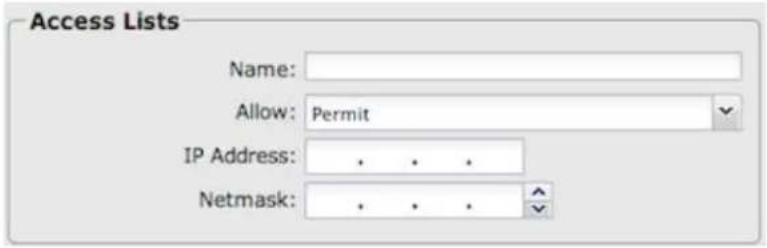
• Name: Choose a unique name.
- Allow: Select "Permit" or "Deny".
• IP Address: Input the IP addresses that you want permitted or denied.
- Netmask. Use this along with "IP Address" to specify a range of IP Addresses associated with this Access Lists rule.
Route Map
Route maps provide a means to filter and/or apply actions to routes, allowing policies to be applied to routes. Route maps define rules for transferring between different routing protocols. Each statement in a route map is ordered. Once there is a match to a statement, the statement is executed and the scan terminates.
Click Add to create a new route map.

• Name: Choose a unique name.
- Allow: Select "Permit" or "Deny".
• Order: Input a number to set the order of this policy.
Match and Set: Both of these have the following configuration options:
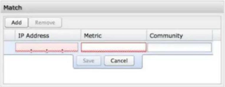
• IP address: Input an IP address with this policy.
• Metric: Numerical priority of the route.
- Community: The BGP community list is a user-defined BGP communities attribute list. The BGP community list can be used for matching or manipulating BGP communities attribute in updates. The community attributes are a 32-bit number that also has some aliases.
- internet: alias for well-known communities value 0
- no-export: alias for well-known communities value NO_EXPORT (0xffff01)
- no-advertise: alias for well-known communities value NO_ADVERTISE (0xFFFF102)
- local-AS alias for well-known communities value NO_EXPORT_SUBCONFED (0xffff03)
Match: This specifies the policy implied if the "Matching Conditions" are met or not met, and which actions of the route map are to be taken, if any. The two possibilities are
- Permit: If the entry matches, then carry out the "Set Actions". Then finish processing the route map, permitting the route, unless an "Exit Action" indicates otherwise.
- Deny: If the entry matches, then finish processing the route-map and deny the route (return "deny").
Set: A route-map entry may, optionally, specify one or more 'Set Actions' to set or modify attributes of the route.
WiFi / Local Networks
This section is used to configure the settings for networks created by your router (LAN). Note that changes made in this section may also need to be duplicated on wireless devices that you want to connect to your wireless network.
For example, if you change a wireless LAN's IP address, devices within that network will lose connection. They will have to reconnect to the network.
The user can set up multiple networks on the router, each with its own unique configuration and its own selection of interfaces. Each local network can be attached to any of the following types of interfaces:
• WiFi
- Ethernet
• VLAN
For example, one network might be just an isolated WIFI hotspot for guests, while another might be the main network with administrative access, an Ethernet port, a password protected WIFI SSID, and a VLAN interface.
Local IP Networks
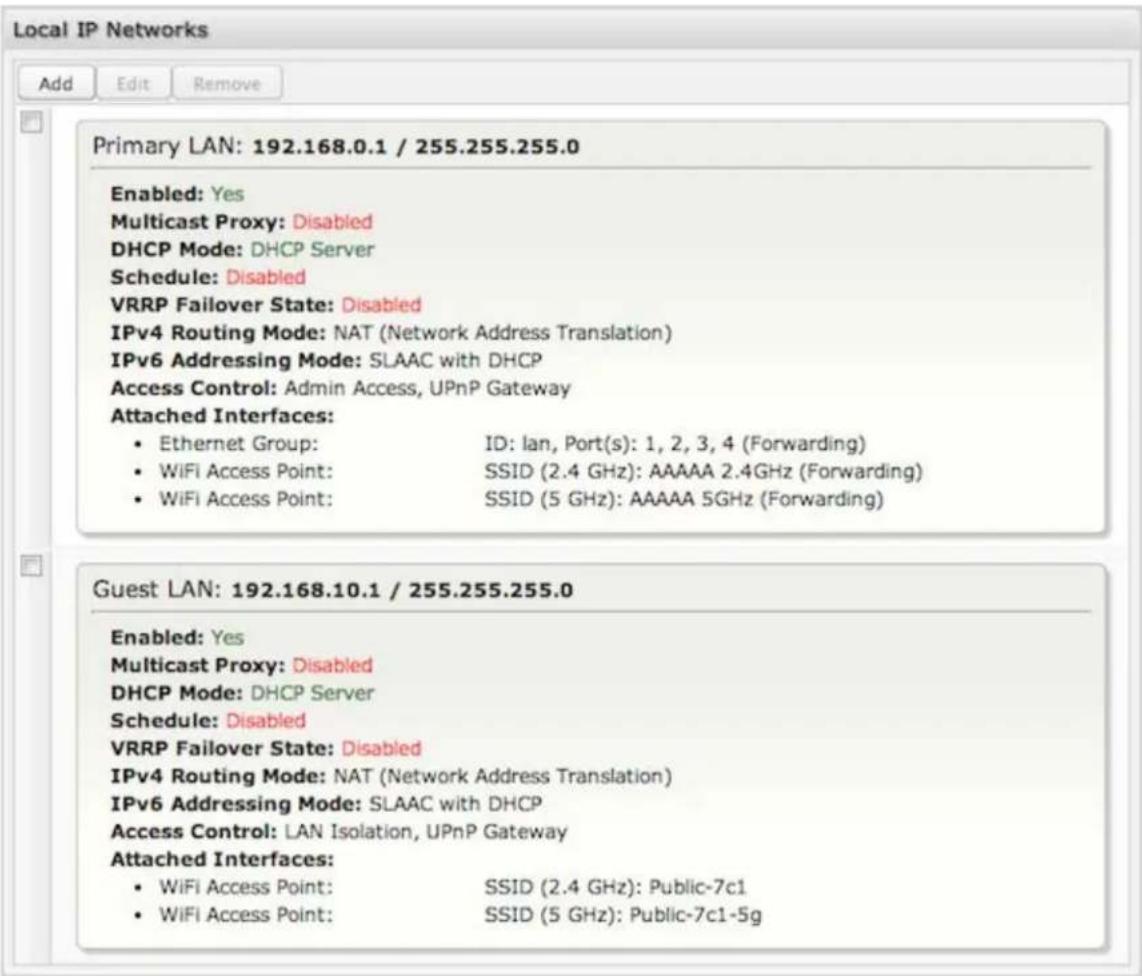
Local IP Networks displays the following information for each network:
• Network Name and IP address/Netmask (along the top bar)
- Enabled: Yes/No
• Multicast Proxy (Enabled/Disabled)
• DHCP Server (Enabled/Disabled)
- Schedule (Enabled/Disabled - See the Schedule tab in the Local Network Editor)
• VRRP Failover State (Disabled, Backup, or Master)
• IPv4 Routing Mode (NAT, Standard, IP Passthrough, Hotspot, Disabled)
• IPv6 Addressing Mode (SLAAC Only, SLAAC with DHCP, Disable SLAAC and DHCP)
• Access Control (Admin Access, UPnP Gateway, LAN Isolation)
- Attached Interfaces (Ethernet ports, WiFi, VLAN)
Click Add to configure a new network, or select an existing network and click Edit to view configuration options.
Local Network Editor
Click Add or select a network and click Edit to open the Local Network Editor to make configure a LAN. The Local Network Editor contains the following tabs: General Settings, IPv4 Settings, IPv6 Settings, Interfaces, Access Control, IPv4 DHCP, IPv6 Addressing, Multicast Proxy, Schedule, VRRP, STP, and Wired 802.1X.
General Settings
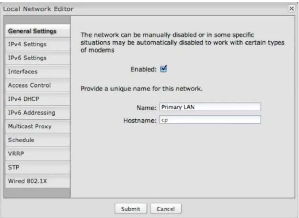
Enabled: Click to manually disable a network. Also, some settings could cause a network to be automatically disabled: click here to re-enable the network.
Name: This primarily helps to identify this network during other administration tasks.
Hostname: [Default: cp (for CradlePoint)] The hostname is the DNS name associated with the router's local area network IP address.
NOTE: You can access the router's administration pages by typing the hostname into your browser, so if you change "cp" to another hostname, you can access the administration pages through the new hostname.
IPv4 Settings
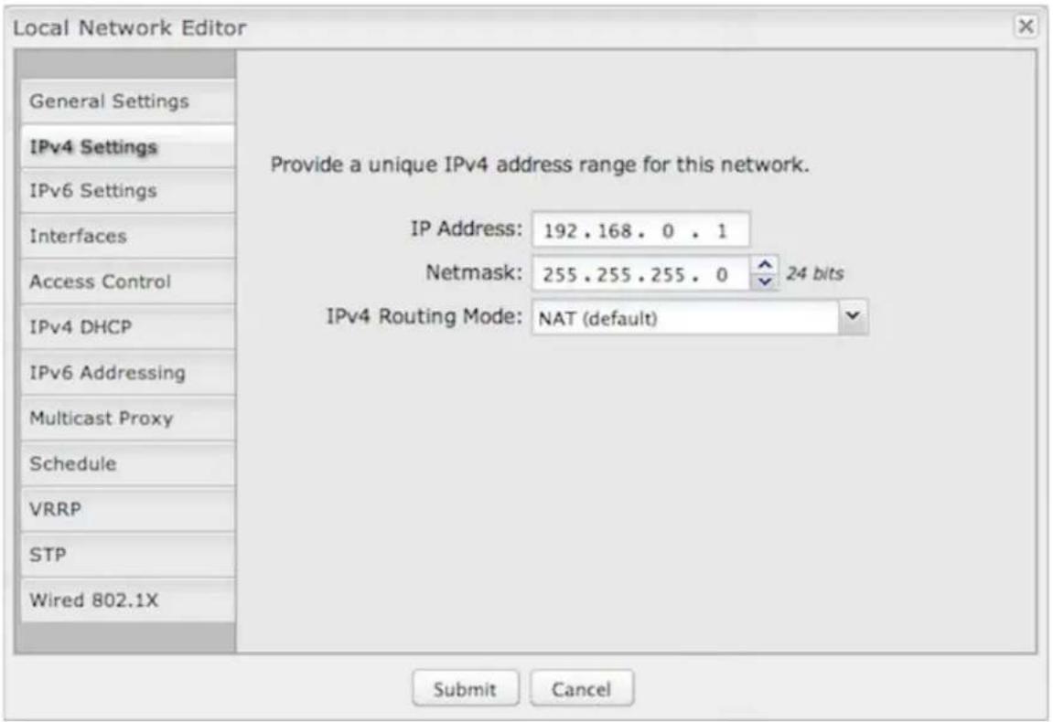
IP Address This is the address used by the router for local area network communication. Changes to this parameter may require a restart to computers on this network.
Each network must have a distinct IP address. Most users will want an address from one of the following private IP ranges:
• 10.0.0.1 - 10.255.255.1
• 172.16.0.1 - 172.31.255.1
• 192.168.0.1 - 192.168.255.1
NOTE: The final number does not have to be 1, but it is a simple, logical convention for routers that leaves higher numbers free for other devices.
Netmask (Default: 255.255.255.0) The netmask controls how many IP addresses can be used in this network. The default value allows for 254 IP addresses.
IPv4 Routing Mode: (Default: NAT) Each network can use a unique routing mode to connect to the Internet and other local networks. NAT is desirable for most configurations. Select from the following options in the dropdown list:
- NAT: Network Address Translation hides private IP addresses behind the router's IP address. This is the simplest and most common choice for users, because NAT does the translation work for you.
- Standard: NAT-less routing. If you select Standard, you must separately configure your IP addresses so that they will be publicly accessible. Typically you will not select this option unless you have a specific reason to bypass NAT.
- IP Passthrough: IP Passthrough passes the IP address given by a cellular modem (WAN) through the router to Ethernet (LAN). All Ethernet ports must be in LAN mode (or disabled) and Hotspot, VPN, and GRE must be disabled. Any wireless interfaces must be removed from this network in order to enable IP Passthrough. The easiest way to enable IP Passthrough mode is with the IP Passthrough Setup Wizard (see Getting Started → IP Passthrough Setup).
- Hotspot: Provide Hotspot Services on this network, requiring Terms of Service or RADIUS/UAM authentication before WAN access will occur on both wireless and wired LAN connections. To enable a Hotspot you must also configure your Hotspot settings under System Settings → Hotspot Services.
• Disabled: Disable this network.
IPv6 Settings
IPv6 must be enabled through the WAN initially: go to Internet → Connection Manager to enable IPv6.
IPv6 Address Source: By default, this is set to Delegated, which means the IPv6 address range for the LAN is passed through from the WAN side. Change this to Static to input your own IPv6 address range here, or select None to explicitly disable IPv6 LAN connectivity.
Interfaces
Select network interfaces to attach to this network. Choose from WiFi, Ethernet ports, and VLAN interfaces. Double-click on any of the interfaces shown on the left in the Available section to move them to the Selected section on the right (or highlight an interface and click the "+" button). To deselect an interface, double-click on an interface in the Selected section (or highlight the interface and click the "-" button).
If you want more interface options, you must configure additional WiFi, Ethernet ports, and VLAN interfaces separately. See the Local Network Interfaces section below (on this same administration page: Network Settings → WiFi / Local Networks).
Access Control
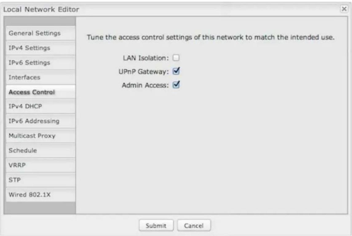
Tune the access control settings of this network to match the intended use. Simply select or deselect any of the following:
• LAN Isolation: When checked, this network will NOT be allowed to communicate with other local networks.
- UPnP Gateway: Select the UPnP (Universal Plug and Play) option if you want to enable the UPnP Gateway service for computers on this network.
- Admin Access: When enabled, users may access these administration pages on this network.
IPv4 DHCP
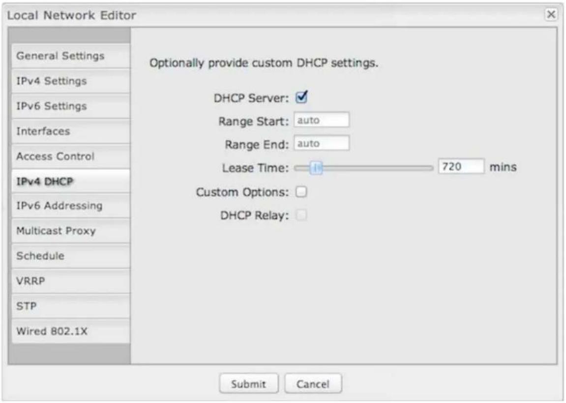
Changing settings for the IPv4 DHCP server is optional. The default selections are almost always sufficient.
DHCP Server: (Default: Enabled) When the DHCP server is enabled, users of your network will be able to automatically connect to the Internet without any special configuration. It is recommended that you leave this enabled. Disabling the DHCP server is only recommended if you have another DHCP server on your network and it is configured properly.
Range Start and Range End: These designate the range of values in the reserved pool of IP addresses for the DHCP server. Values within this range will be given to any DHCP enabled computers on your network. The default values are almost always sufficient (default: 72 to 200, as in 192.168.0.72 to 192.168.0.200).
Example: The router uses an IP address of 192.168.0.1 for its primary network by default. A computer designated as a Web server has a static IP address of 192.168.0.3. Another computer is designated as an FTP server with a static IP address of 192.168.0.4. The starting IP address for the DHCP server needs to be 192.168.0.5 or higher.
Lease Time: [Default: 720 minutes (12 hours)] The lease time specifies how long DHCP-enabled computers will wait before requesting a new DHCP lease. Smaller values are better suited to busy environments.
Custom Options: Input a custom DHCP option by first clicking the Custom Options field to enable it and then clicking "Add" at the top of the table that appears. There are close to 200 possible DHCP options available. One of the more common uses is to assign a VoIP phone server using option 66 (Server name).
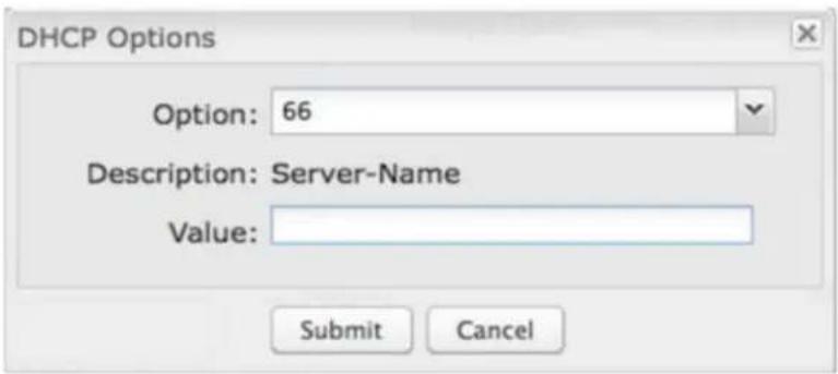
- Option: Select an option from the dropdown list or manually enter the number of an option. A complete list of options is available from IANA.
- Value: Generally this field should be a string, IP address, or numeric value. Some fields can accept both IP addresses and hostnames – in these cases you may
need to wrap this value in quotes. For example, option 66 (Server name) requires quotes around IP addresses.
DHCP Relay: DHCP Relay communicates with a DHCP server and acts as a proxy for DHCP broadcast messages that must be routed to remote segments. This is accomplished by converting broadcast DHCP messages to unicast messages to communicate between clients and servers.
DHCP Server Address: An optional DHCP server address if more than one DHCP server is located on the network. This field is only available when DHCP Relay is enabled.
IPv6 Addressing
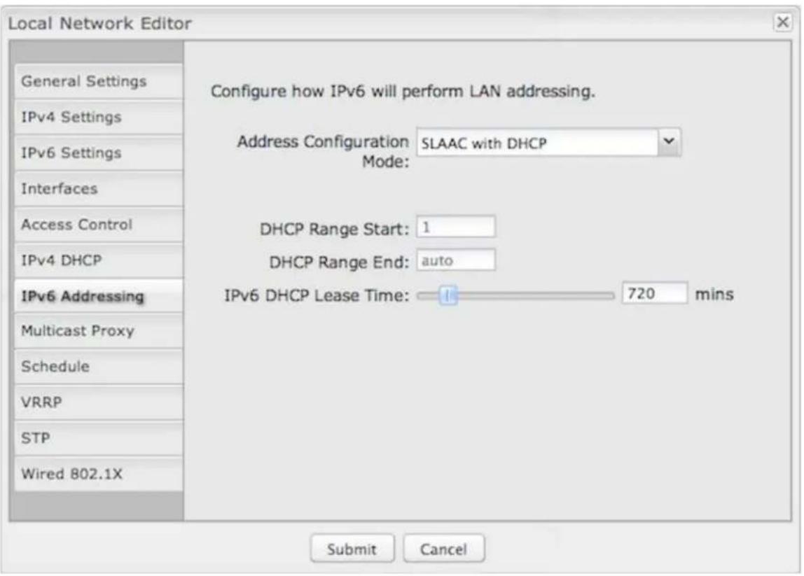
Address Configuration Mode: Select from the following dropdown options:
- SLAAC Only – SLAAC stands for stateless address autoconfiguration. The router regularly generates a router advertisement that includes network prefix and routing information, allowing clients to autogenerate an address and start communicating on the network. Clients utilize neighbor discovery protocols to ensure multiple clients on the subnet have not chosen an identical address.
-
SLAAC with DHCP – (Delault) IPv6 DHCP provides an additional client configuration method and is regularly combined with SLAAC to provide DNS servers (a shortcoming in the original SLAAC specification) and additional options not supported by SLAAC. By defaulting to SLAAC with DHCPv6, all IPv6-capable clients on the network should be configurable with IPv6 connectivity.
-
DHCP Range Start: The beginning of the range that will be used for IPv6 DHCP addresses. The IPv6 range will always start at 1.
- DHCP Range End: The ending IP address in the DHCP Server range is the end of the reserved pool of IP addresses that will be given to any DHCP-enabled computers on your network.
- IPv6 DHCP Lease Time: This specifies how long DHCP-enabled computers will wait before requesting a new DHCP lease.
- Disable SLAAC and DHCP – Disable both IPv6 address configuration modes.
Multicast Proxy
IGMP (Internet Group Management Protocol) multicast proxy allows a single packet to reroute to multiple destinations (see the Wikipedia explanation of multicast). This may be used for IPTV, for example.
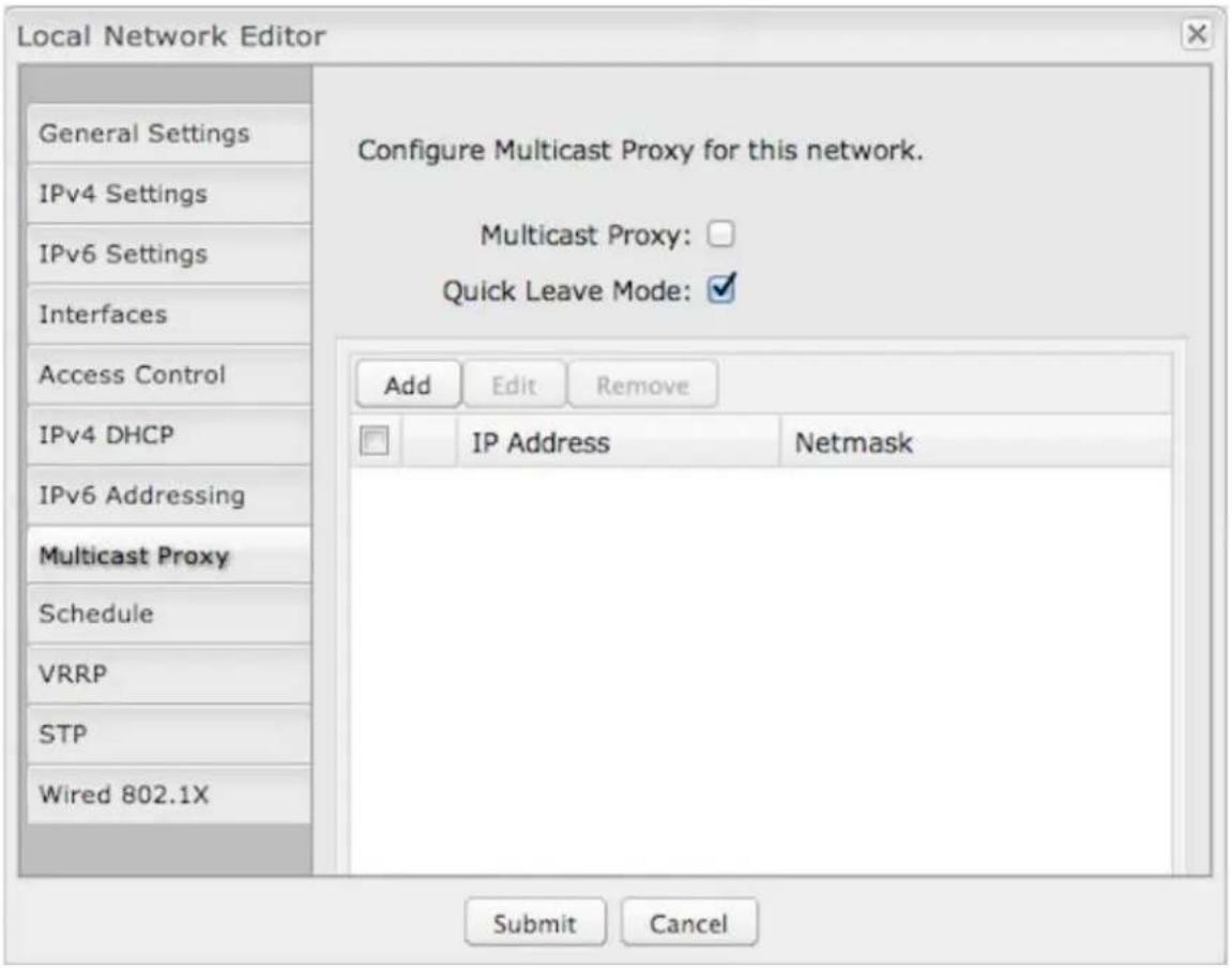
Multicast Proxy: Select to enable IGMP proxy support to allow multicast streams to flow across this network.
Quick Leave Mode: Disable quick leave mode if it's vital that the daemon should act exactly as a real multicast client on the upstream interface. However, disabling this function increases the risk of bandwidth saturation.
By default, enabling multicast proxy enables a multicast connection with devices within the LAN. In rare cases, additional IP address ranges need access to the multicast streams. Click Add and input the IP Address and Netmask for an additional IP address range.
Schedule
Set up a schedule for this network interface. This allows an interface to be enabled or disabled during specific hours of a day. For example, use this to limit a Hotspot network to business hours.
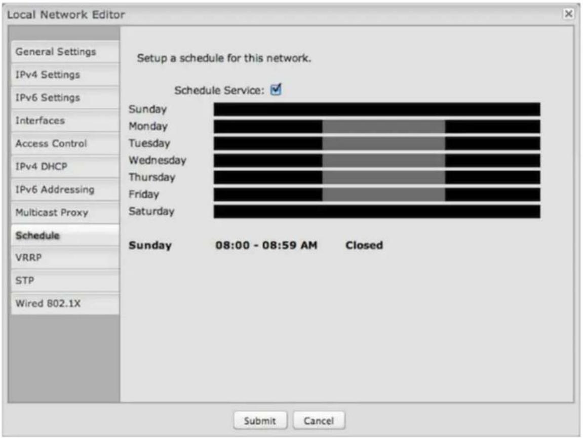
Schedule Service: (Default: Disabled.) Select to enable. This will open a configurable chart for setting the schedule.
Each hour of the week is represented by a black or gray square. Black represents disabled, while gray represents enabled. Hover over a square to reveal the hour it represents. Click on the squares to toggle between black and gray.
In the example shown, the network is enabled from 8-5 on Monday through Friday, but disabled at all other times.
VRRP
NOTE: VRRP requires a feature license. Go to System Settings → Feature Licenses to enable this feature.
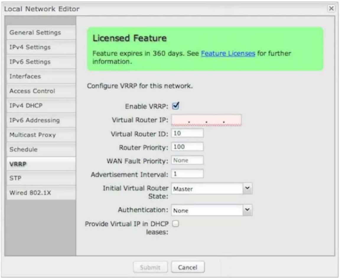
VRRP (Virtual Router Redundancy Protocol) allows you to associate multiple routers with one LAN so that if the primary physical router fails, the LAN will keep the same settings via the virtual router.
Enable VRRP: Select to enable VRRP configuration options.
Virtual Router IP: IP address of the virtual router. This must be distinct from the IP address of any physical router associated with the virtual router.
Virtual Router ID: Identifying number of the virtual router. (Range: 1-255)
Router Priority: Failover priority level of this physical router. The physical router with the highest priority number will have primary ownership of the virtual router. (Range: 1-254)
WAN Fault Priority: This optional value sets the failover priority of this router when no WAN connection is available. If the value matches the normal router priority, WAN connection state will not be considered. If the value is empty (the default), the router will always give up ownership of the virtual IP and let a new master take over when no WAN connection is available.
Advertisement Interval: Sets the amount of time (in seconds) between VRRP advertisements, which communicate the router status. The default of 1 second is standard.
Initial Virtual Router State: This controls the initial VRRP fallover state for this physical router; choose Master or Backup. This sets up the virtual router association more quickly than the Router Priority level, but the Router Priority assignment will eventually overrule this if there is a discrepancy.
Authentication: VRRP Authentication Method. This is for legacy purposes: VRRP Authentication has been deprecated as of RFC 3768. Select None or Simple. If you select Simple, input a VRRP group password.
Provide Virtual IP in DHCP leases: Select this to automatically set the DHCP default gateway address and DNS server address to the virtual IP in DHCP leases provided on this network.
STP
NOTE: STP requires a feature license. Go to System Settings → Feature Licenses to enable this feature.
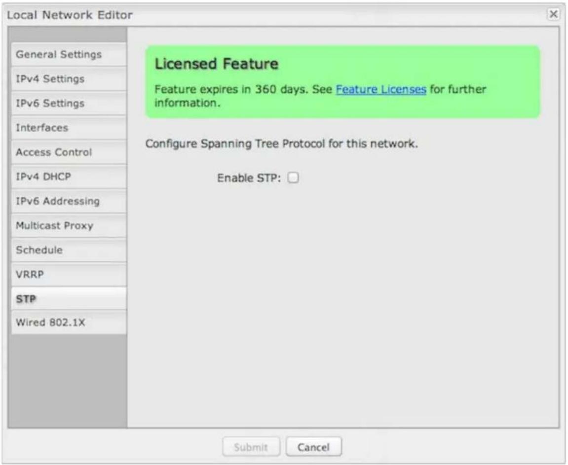
Spanning Tree Protocol (STP) allows a network design to include redundant paths while preventing broadcast radiation from bridge loops.
Enable STP: Enable Spanning Tree Protocol loop detection.
Bridge Priority: Set the priority of the bridge. When determining the root bridge of the spanning tree topology, the bridge priority is compared first. The bridge with the lowest priority value will win. If you want this router to be the root bridge, then set it to a value less than the default of 32768. A valid priority value is between 0 and 65535.
Wired 802.1X
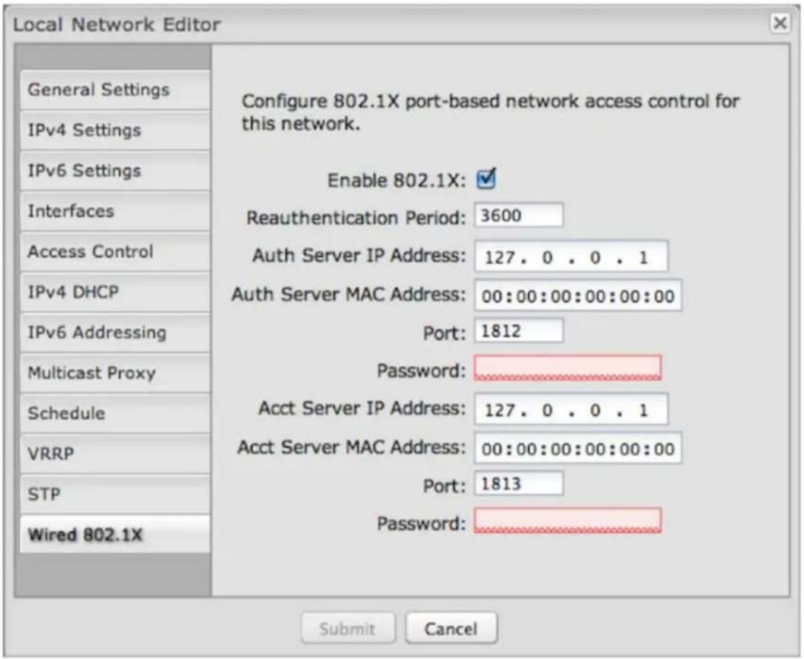
Wired 802.1X: (requires hardware version 2.0) This allows you to configure an authentication server that will accept authentication requests from devices attached to wired Ethernet ports. IEEE 802.1X defines the encapsulations of the Extensible Authentication Protocol (EAP).
Click Enable 802.1X to require IEEE 802.1X authorization for the Ethernet ports associated with this network.
Reauthentication Period: EAP re-authentication period in seconds.
Authentication settings
- Auth Server IP Address This is the IP address of the connected RADIUS server.
- Auth Server MAC Address: This is the hardware address of the connected RADIUS server's interface. NOTE: If you don't know the MAC address for the RADIUS server, enter 00:00:00:00:00:00 and the service will try to find the MAC address from the given IP address.
• Port: 1812 is common for the authentication port.
• Password: Assigned by the RADIUS server.
Accounting settings: Most of the accounting settings often match the authentication settings, depending on whether the RADIUS server is the same for both authentication and accounting.
• Acct Server IP Address
• Acct Server MAC Address
• Port: 1813 is common for the accounting port.
- Password
Local Network Interfaces
Each LAN type — WiFi, Ethernet, and VLAN — has a separate section with configuration options. Unless the default configuration is sufficient, YOU MUST CONFIGURE EACH INTERFACE SEPARATELY in order to create the desired interface options for a network. You can then select these interfaces to add to a network in the Local Network Editor (see above).
Local Network Interfaces
WiFi Radio #1 Settings (2.4 GHz)
WiFi Radio #2 Settings (5 GHz)
Ethernet Port Configuration
VLAN Interfaces
Select from the following tabs:
• WiFi Radio #1 Settings (2.4 GHz)
• WiFi Radio #2 Settings (5 GHz)
- Ethernet Port Configuration
• VLAN Interfaces
Wireless (WiFi) Network Settings
Each wireless radio (2.4 GHz and 5 GHz) can broadcast as many as four SSIDs (service set identifiers – the names for WiFi networks). One primary WiFi network is enabled by default, while you may have enabled a second guest network when using the First Time Setup Wizard. You have the ability to change the settings for either of these networks and/or enable additional networks.
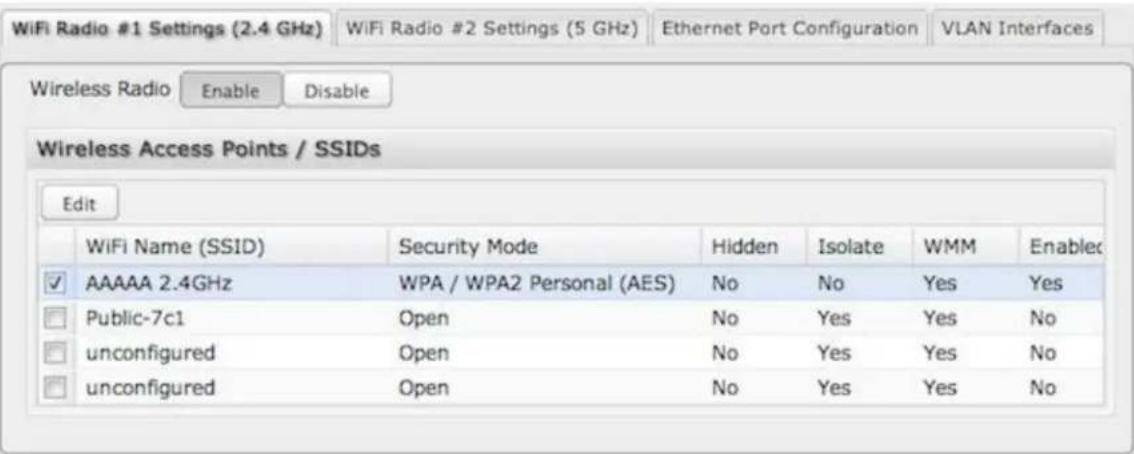
Wireless Radio: Enable/Disable. (Default: Enabled). Leave enabled unless you don't want any WiFi networks broadcast from your router.
Select a WiFi network and click Edit to change the settings.
Wireless Network Editor
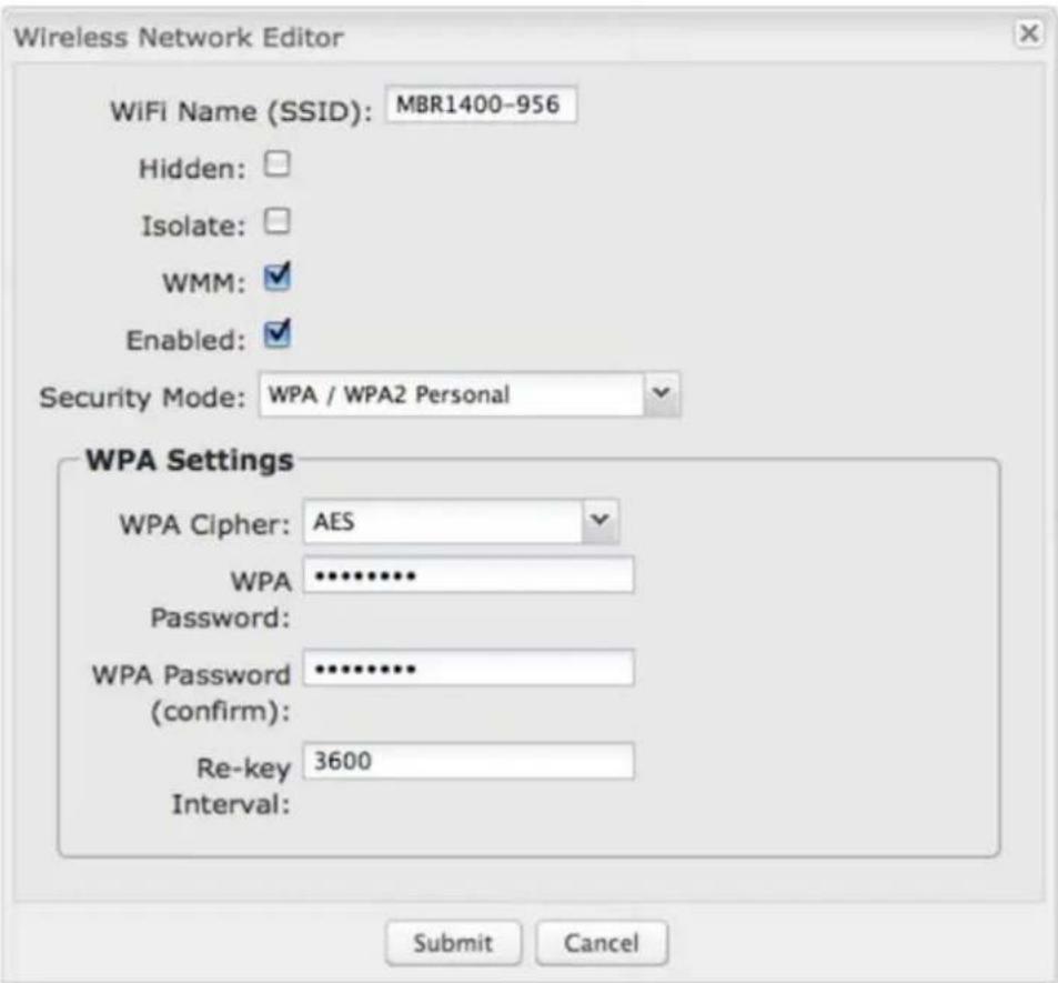
WiFi Name (SSID): When users browse for available wireless networks, this is the name that they will see. This name is referred to as the SSID (service set identifier). For security purposes, CradlePoint highly recommends that you change this from the pre-configured name.
Hidden: This shows whether the router broadcasts its SSID. It is somewhat harder for hackers to find and attack a router that is not broadcasting its SSID, which adds to the wireless security, but it is also more difficult for friendly users to attach to a WiFi network with a hidden SSID.
Isolate: Select this to isolate all wireless clients so they cannot directly communicate with each other on the wireless network.
WMM: WiFi Multimedia. This is a basic traffic shaping, or QoS (quality of service), system for the network. WMM works behind the scenes to set priorities for different types of traffic on your network. For example, video streams are given higher priority than print jobs, since video streams need consistent throughput.
Enabled: Whether the network is available.
Security Mode: You have several options for selecting a security mode. The mode you choose depends on the security features your wireless adapters support.
WPA2 Personal
• WPA / WPA2 Personal
WPA Personal
WPA2 Enterprise
• WPA / WPA2 Enterprise
WPA Enterprise
• WEP Auto
Open
Select "Open" to create a hotspot: otherwise select the best security that your devices will support (CradlePoint recommends WPA2).
Depending on which Security Mode you select, there are different setup options.
• "Personal" security modes require passwords.
- "Enterprise" security modes are linked to a RADIUS server and require RADIUS authentication: IP, Port, and Shared Key (Secondary IP and NAS ID optional).
• "WPA2" (Personal or Enterprise) forces AES as the WPA Cipher.
- "WPA/WPA2" and "WPA" (Personal or Enterprise) allow AES, TKIP/AES, and TKIP.
• "WEP Auto" requires a WEP Key. - "Open" has no password or other security measures.
NOTE: If you don't know whether you should choose Personal or Enterprise, assume Personal since you need to know RADIUS authentication for Enterprise.
In order to protect your network from hackers and unauthorized users, CradlePoint highly recommends WPA2/AES for security if your attached devices can support it. WEP and WPA/TKIP are obsolete and have been replaced by WPA/AES. Using those security settings will cause the WiFi to limit to 802.11g modes.
NOTE: If you select one of the security modes and are unable to connect to the router afterwards, you can use the reset buttons to reset the router to its factory default state and try a different security mode instead.
Ethernet Port Configuration
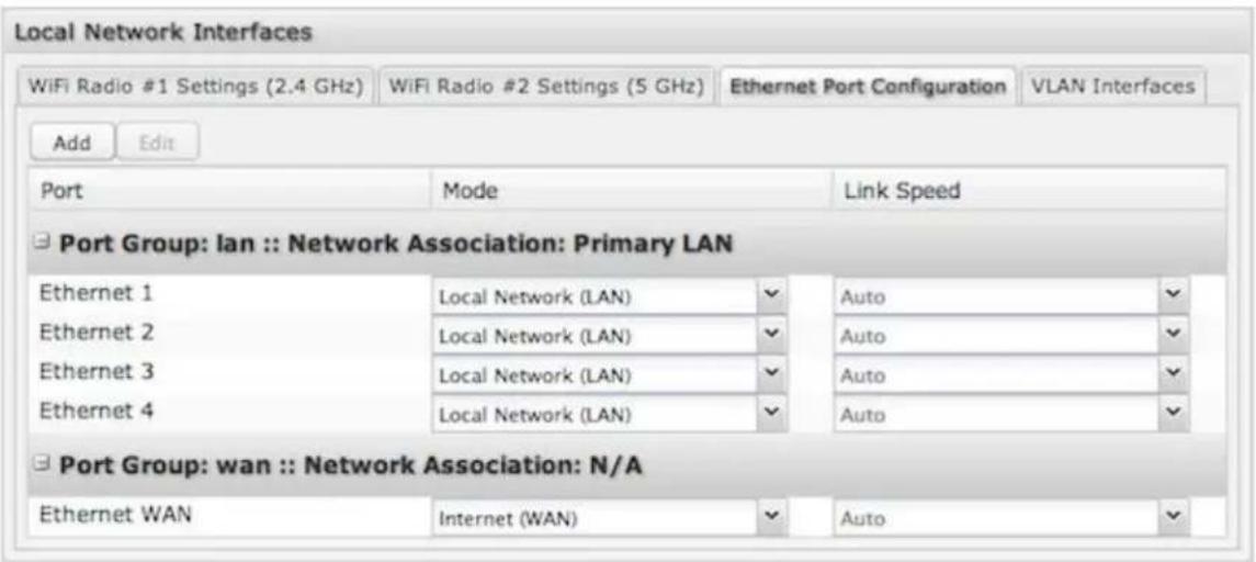
Ethernet Port Configuration provides controls for your router's Ethernet ports. There are five total ports: by default, one WAN port and four numbered LAN ports. While default settings will be sufficient in most circumstances, you have the ability to control: Mode (WAN or LAN) and Link Speed. Additional controls for WAN ports are available in Internet → Ethernet Settings.
Mode: WAN or LAN. By default there are four LAN (Local Area Network) ports and one WAN (Wide Area Network) port.
- Internet (WAN) is used as a possible source of Internet for the router.
- Local Network (LAN) is for connecting a computer or similar device directly to the router with an Ethernet cable.
Link Speed: Default setting is Auto. The Auto setting is preferred in most cases.
• Auto
• 10Mbps - Half Duplex
• 10Mbps - Full Duplex
• 100Mbps - Half Duplex
• 100Mbps - Full Duplex
• 1000Mbps - Full Duplex
Ethernet Port Group Editor
A Port Group represents a logical grouping of Ethernet ports. Any computers physically connected to ports in a group will be allowed to freely communicate with each other. For example, if you keep the four default LAN ports, you might group ports 1 and 2 together to be part of your primary network, and then group ports 3 and 4 together to be part of a guest network.
NOTE: When a port group uses the LAN mode you must separately ensure that this logical interface is attached to a Local IP Network in the top panel of this page.
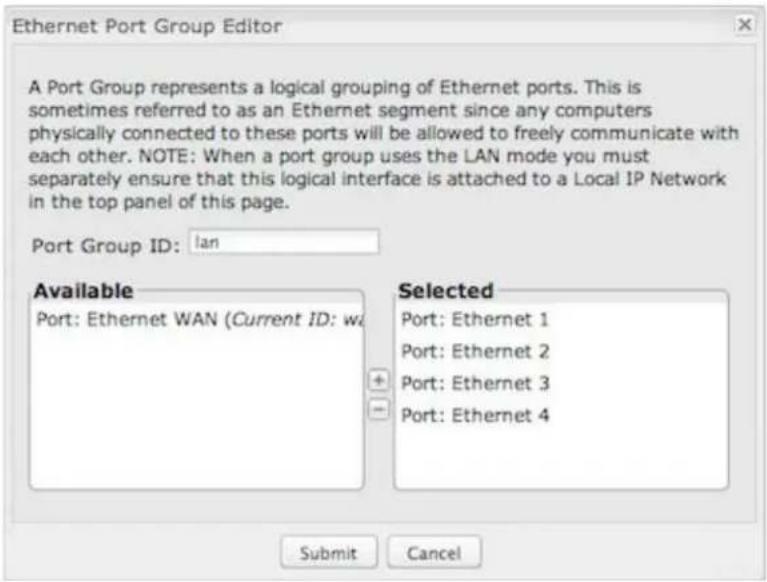
Port Group ID: The Group ID field provides a reference to this grouping of ports to be used in other parts of the router configuration. For example, this ID is referenced in the Local IP Networks configuration to attach this logical group of Ethernet ports with a network configuration. Use a simple short text phrase to describe this group, such as "main", "guestports", "backup_wan", etc. This must be unique.
Select one or more ports to create a port group that you can subsequently attach to a network in the Local Network Editor. Double-click on any of the Ethernet ports shown on the left in the Available section to move them to the Selected section on the right (or highlight a port and click the + button). To deselect an Ethernet port, double-click on an interface in the Selected section (or highlight the port and click the - button).
VLAN Interfaces
A virtual local area network, or VLAN, functions as any other physical LAN, but it enables computers and other devices to be grouped together even if they are not physically attached to the same network switch.
To enable a VLAN, select a VID (virtual LAN ID) and a group of Ethernet ports through which users can access the VLAN. Then go back up to the Local Network Editor to attach your new VLAN to a network. To use a VLAN, the VID must be shared with another router or similar device so that multiple physical networks have access to the one virtual network.
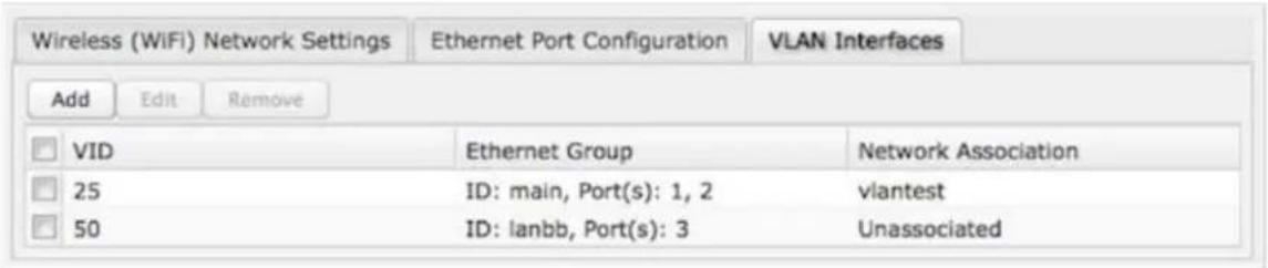
Click Add to create a new VLAN interface.
VLAN Editor
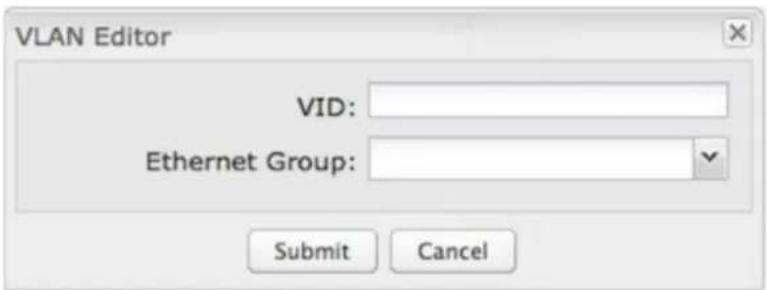
VID: An integer value that is the Virtual LAN ID.
Ethernet Group: Select the LAN port(s) with which you want to associate the VLAN ID from a dropdown list. Your Ethernet group must be created separately under Ethernet Port Configuration.
Click Submit to save your configured VLAN.
WiFi Settings (Advanced)
When you select either of the WiFi tabs (2.4 GHz or 5 GHz) in the Local Network Interfaces section, you have several additional options for configuring your wireless LANs under the WiFi Settings heading.
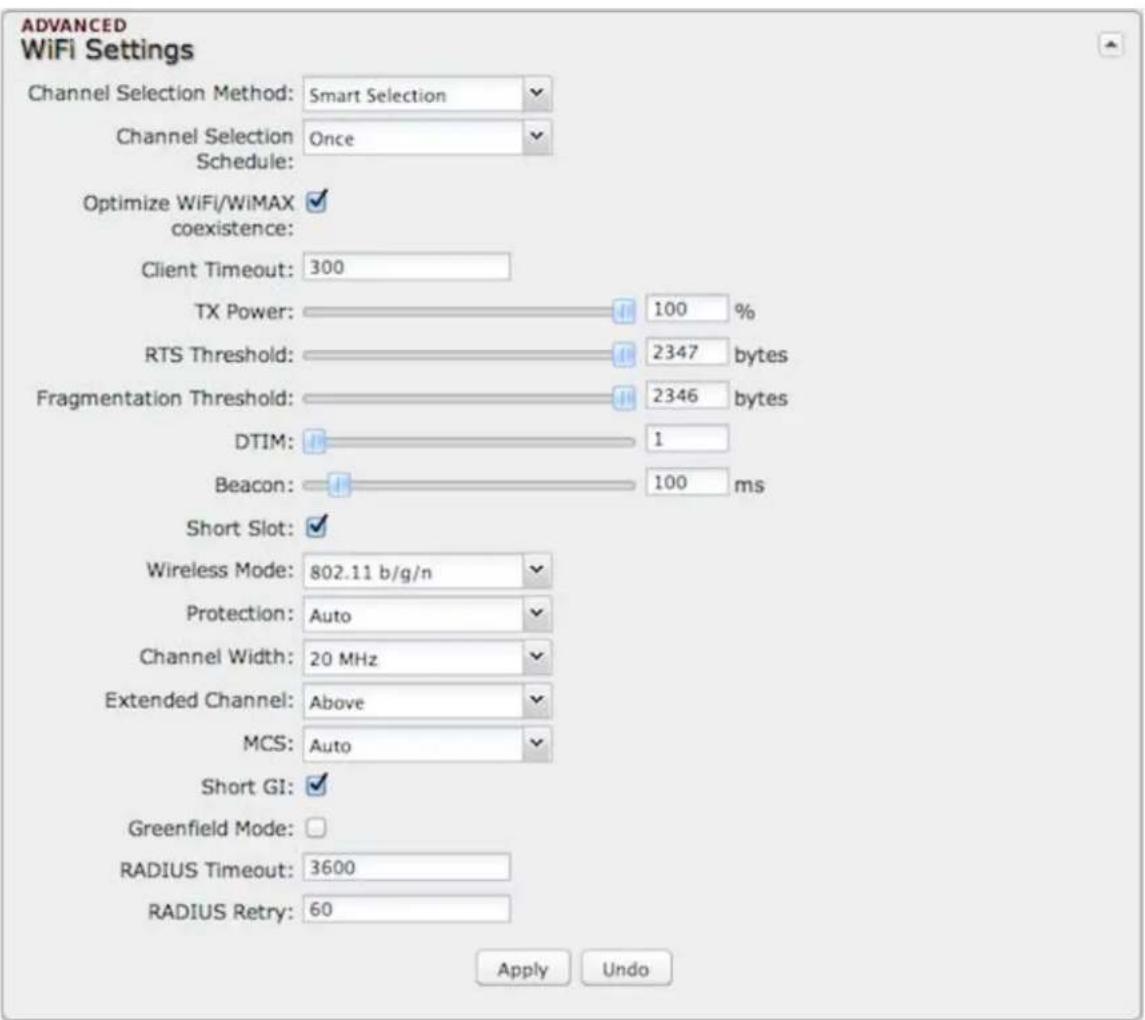
Channel Selection Method: This controls how a WiFi channel is selected.
- User Selection – Manually set the channel.
• Random Selection – The router randomly sets the channel. - Smart Selection (Default) – Scans to determine the lowest interference WiFi channel.
Channel Selection Schedule: When using the "Smart" channel selection, this controls whether the router will periodically rescan for a better channel and change to it. Select from "Once," "Daily," "Weekly," or "Monthly." Note that there may be a momentary WiFi disconnection while the channel changes.
Optimize WiFi/WiMAX coexistence: (Shows if Smart Selection or Random Selection is chosen and the WiFi band is 2.4 GHz.) Setting this will lessen any possible conflict with WiFi in the 2.4 GHz band and an attached WiMAX modem. If a WiMAX modem is attached to the router when the WiFi is enabled, the WiFi channel and transmit power will be set to levels that optimize the performance of the WiMAX modem. If no WiMAX modem is attached, then default channel and power settings will be used even if this is selected.
Channel: (Shows if User Selection is selected.) The WiFi channel corresponds to a frequency the router uses to communicate with other devices. For 2.4 GHz, the range is 1 to 11, and 1, 6, and 11 do not overlap each other. If a WiMAX modem is attached, a higher number channel will increase the chance the router's WiFi and modem's
WiMAX radios will conflict with each other, which may result in lower throughput. Select a channel from the dropdown list:
• 1 (2412 MHz)
• 2 (2417 MHz)
3 (2422 MHz)
4 (2427 MHz)
5 (2432 MHz)
6 (2437 MHz)
7 (2442 MHz)
8 (2447 MHz)
9 (2452 MHz)
• 10 (2457 MHz)
• 11 (2462 MHz)
For 5.0 GHz, the ranges are 36 to 64 and 149 to 165. These channels do not interfere with a WiMAX modem.
• 36 (5180 MHz)
40 (5200 MHz)
44 (5220 MHz)
48 (5240 MHz)
149 (5745 MHz)
• 153 (5765 MHz)
• 157 (5785 MHz)
• 161 (5805 MHz)
165 (5825 MHz)
Client Timeout: If the access point is not able to communicate with the client it will disconnect it after this timeout (in seconds).
TX Power: Normally the wireless transmitter operates at 100% power. In some circumstances, however, there might be a need to isolate specific frequencies to a smaller area. By reducing the power of the radio, you can prevent transmissions from reaching beyond your corporate/home office or designated wireless area. RTS Threshold: When an excessive number of wireless packet collisions are occurring, wireless performance can be improved by using the RTS/CTS (Request to Send/Clear to Send) handshake protocol. The wireless transmitter will begin to send RTS frames (and wait for CTS) when data frame size in bytes is greater than the RTS Threshold. This setting should remain at its default value.
Fragmentation Threshold: Wireless frames can be divided into smaller units (fragments) to improve performance in the presence of RF interference and at the limits of RF coverage. Fragmentation will occur when frame size in bytes is greater than the Fragmentation Threshold. This setting should remain at its default value. Setting the Fragmentation value too low may result in poor performance.
DTIM: A DTIM is a countdown informing clients of the next window for listening to broadcast and multicast messages. When the wireless router has buffered broadcast or multicast messages for associated clients, it sends the next DTIM with a DTIM Interval value. Wireless clients detect the beacons and awaken to receive the broadcast and multicast messages. The default value is 1. Valid settings are between 1 and 255.
Beacon: Beacons are packets sent by a wireless router to synchronize wireless devices. Specify a Beacon Period value between 20 and 1000 milliseconds.
WPS: WiFi Protected Setup is a method for easy and secure establishment of a wireless network. It can be used instead of passwords when connecting clients that support WPS.
Short Slot: Slot Time is the period wireless clients use in determining if the channel is free for transmission. Enabling this value allows clients that can utilize a shorter time to do so. Disabling this option forces all clients to use a longer backoff check and thus may reduce network throughput while reducing the number of transmission collisions.
Wireless Mode: Select the WiFi clients the router will be compatible with. Greater compatibility is a tradeoff with better performance. For greatest compatibility with all WiFi devices, select "802.11 a/b/g/n". For best performance, connect with only other 802.11n-compatible devices and select "802.11 n."
802.11 b
802.11 b/g
802.11 a/b/g/n
802.11 b/g/n
802.11 n
Channel Width: Selects whether the router uses a single 20 MHz channel to send/receive, or uses two adjacent 20 MHz channels to create a 40 MHz channel. Higher performance is possible with the 40 MHz channel. Selecting Auto is generally best. Enabling WiFi as WAN will force 20 MHz only mode.
Extended Channel: When operating in 40 MHz mode the access point will use an extended channel either below or above the current channel. Optimal selection will depend on the channels of other networks in the area.
MCS: 802.11n uses multiple Modulation Coding Schemes to enable higher throughput in various environments. Since clients can dynamically change rates depending on environment, selecting Auto is generally best.
Short GI: Short GI is an optimization for shortening the interval between transmissions. May be incompatible with older clients.
Greenfield Mode: Greenfield mode uses an 802.11n-only preamble to transmit packets that older wireless clients cannot interpret. Use of greenfield mode in a mixed 802.11 environment may result in degraded performance but can improve performance if all devices in the area are 802.11n compatible.
RADIUS Timeout: (Default: 3600 seconds) When using an Enterprise security mode clients will be forced to re-authenticate with the RADIUS server at this interval in seconds. This allows administrators to revoke access so when an attached client's authentication expires, the client must re-authenticate.
RADIUS Retry: (Default: 60 seconds) When using an Enterprise security mode, if a RADIUS query fails to receive a response from the server it will delay by this interval (in seconds) before attempting another query. This helps protect the network from floods of authentication requests if the RADIUS server is temporarily unreachable.
WiPipe QoS
When WiPipe QoS (Quality of Service, also known as "Traffic Shaping") is enabled, the router will control the flow of Internet traffic according to the user-defined rules. In other words, Traffic Shaping improves performance by allowing the user to prioritize applications.
Enable WiPipe QoS: Click on this box to open options for controlling Internet traffic. You can assign maximum Upload Speed and Download Speed values and define your own Traffic Shaping rules.
WAN Interface Speeds
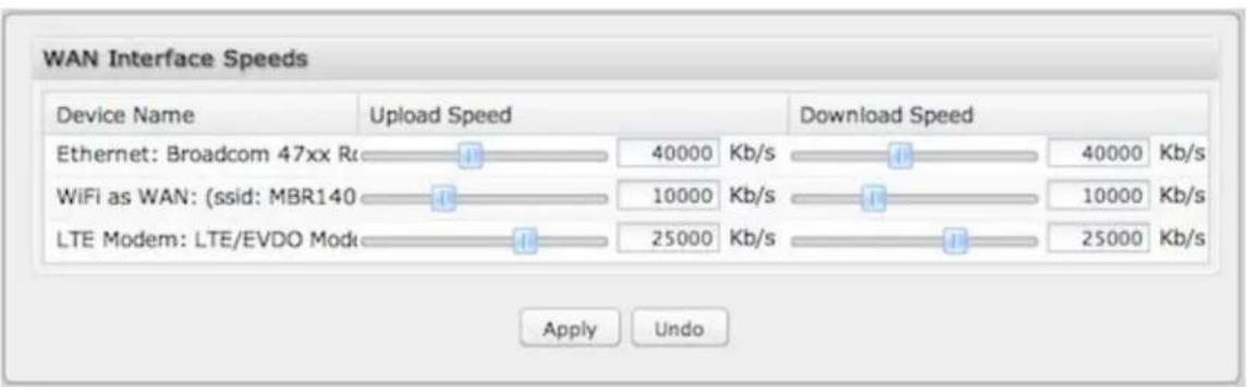
bar
| Device Name | Upload Speed | Download Speed | | --- | --- | --- | | Ethernet: Broadcom 47xx Rc | 40000 | 40000 | | WiFi as WAN: (ssid: MBR140) | 10000 | 10000 | | LTE Modem: LTE/EVDO Mode | 25000 | 25000 |Upload Speed and Download Speed: Setting the Upload Speed and Download Speed is required to control traffic flow accurately. Adjust the sliding bar to restrict the maximum upload and/or download speed for the Internet source(s) you are using. For example, you might restrict the upload speed to prioritize available bandwidth for download or to reduce overall bandwidth use in order to lower costs. It is recommended that you experiment with different values for your particular Internet connection for best results.
NOTE: Upload speed is the speed at which data can be transferred to your ISP. Download speed is the speed at which data can be transferred to you from your ISP. You can test your connection speeds with a service such as speedtest.net.
Queues
Queues and rules work in conjunction to prioritize bandwidth for the most critical operations. Multiple rules can be associated with one queue. Use rules to associate your more critical operations with queues that have higher bandwidth settings. For example, you might have two queues, one for "critical" and one for "secondary" with critical having most of the bandwidth percentage. Use rules to associate your most important bandwidth needs (POS system, VoIP, etc.) with the critical queue. Restrict the bandwidth available for less important functions with the secondary queue.
Assign percentages of both upload and download bandwidth to each queue. If you assign 80% download bandwidth to the first queue, the next queue will be forced to be
20% or less.
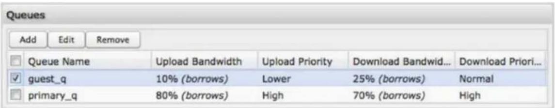
Click Add to create a new Traffic Shaping/QoS queue.
Queue Name: Choose a name that is meaningful to you.
Upload Bandwidth
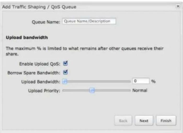
Enable Upload QoS: (Default: Enabled.) Deselect if you want your rule to apply to download traffic only. Leave this selected to include upload restrictions with this queue.
Borrow Spare Bandwidth: (Default: Enabled.) When this is enabled, the interfaces/protocols associated with this rule will borrow unused bandwidth from other rules. Disabling borrowing will restrict the traffic to the specified bandwidth. Higher priority queues will be offered excess bandwidth first.
Upload Bandwidth: This is the percentage of the connected WAN upload bandwidth that will be reserved for the specified traffic. The maximum value is adjusted to the remaining percentage after other rules receive their share.
Upload Priority: The priority value has two different effects on traffic. Higher priority traffic is handled before lower priority traffic, which can lead to shorter response times. Also, when spare bandwidth is available it is offered to higher priority queues first. Move the slider to select from the following options (Default: Normal):
- Lowest
- Lower
Below Normal - Normal
- Above Normal
• High - Higher
- Highest
Click Next to continue to the next page.
Download Bandwidth
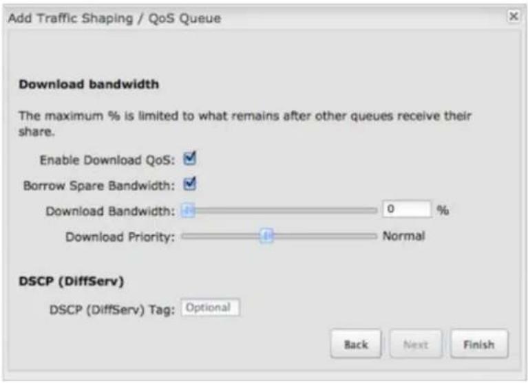
Enable Download QoS: (Default: Enabled.) Deselect if you want your rule to apply to upload traffic only. Leave this selected to include download restrictions with this queue.
Borrow Spare Bandwidth: (Default: Enabled.) When this is enabled, the interfaces/protocols associated with this rule will borrow unused bandwidth from other rules. Disabling borrowing will restrict the traffic to the specified bandwidth. Higher priority queues will be offered excess bandwidth first.
Download Bandwidth: This is the percentage of the connected WAN upload bandwidth that will be reserved for the specified traffic. The maximum value is adjusted to the remaining percentage after other queues receive their share.
Download Priority: The priority value has two different effects on traffic. Higher priority traffic is handled before lower priority traffic, which can lead to shorter response times. Also, when spare bandwidth is available it is offered to higher priority queues first. Move the slider to select from the following options (Default: Normal):
- Lowest
- Lower
Below Normal - Normal
- Above Normal
• High - Higher
- Highest
DSCP (DiffServ) Tag: Differentiated Services Code Point (DSCP) is the successor to TOS (Type of Service). Use this field to 'tag' the traffic by putting the value in the DSCP header of each IP packet that flows through this queue. Use the value of 'O' to clear the existing DSCP value in the packet header.
DSCP Tagging is sometimes used so that other networking equipment, upstream or post-NAT, can do traffic shaping based on the DSCP Tags as opposed to IP addresses or ports.
This setting is optional. For more information see the Differentiated services Wikipedia page.
Click Finish to save this queue.
Rules
A traffic shaping rule identifies a specific message flow and assigns that flow to one of the queues created above.
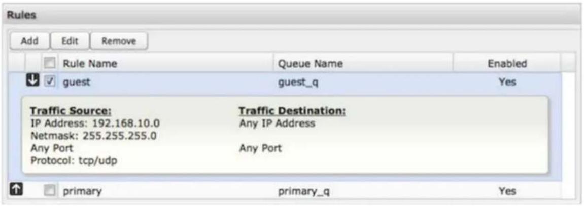
Click Add to create a new Traffic Shaping rule.
Traffic Shaping / QoS Rule Editor
The first page of the Traffic Shaping / QoS Rule Editor allows you enable/disable the rule, name the rule, specify a protocol for the rule, and select a queue to associate the rule with.
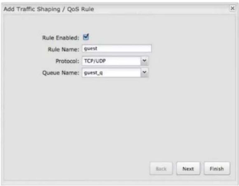
Rule Enabled: (Default: Enabled.) Deselect this to disable this rule. This can be useful for quickly changing configurations. If both upload QoS and download QoS are disabled then the rule will disable automatically.
Rule Name: Create a name for the rule that is meaningful to you.
Protocol: The protocol used by the messages: TCP/UDP, TCP, UDP, or ICMP. Select "Any" if your rule does not control a specific type of message that uses a specific protocol.
Queue Name: Select a queue to associate this rule with.
Click Next to continue to the next page.
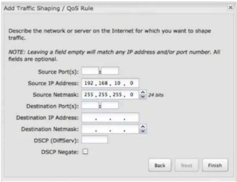
Use ports and/or IP addresses to define the type(s) of traffic attached to this rule. Leaving any field blank will match all values; all fields are optional.
Source Port(s) and/or Destination Port(s): Enter a port number between 1 and 65535. To enter a single port number, input the number into the left box. To enter a range of ports, fill in both boxes separated by the colon. For example "80:90" would represent all ports between 80 and 90 including 80 and 90 themselves.
Source IP Address, Source Netmask, Destination IP Address, and Destination Netmask: Specify an IP address or range of IP addresses by combining an IP address with a netmask for either "source" or "destination" (or both). Source vs. destination is defined by traffic flow. Leave these blank to include all IP addresses (such as if your rule is defined by a particular port instead).
EXAMPLE: If you want to associate this rule with your guest LAN, you could input the IP address and netmask for the guest LAN here (leaving the last slot "0" to allow for any user attached to the guest network):
• Source IP Address: 192.168.10.0
• Source Netmask: 255.255.255.0
DSCP (DiffServ): Differentiated Services Code Point (DSCP) is the successor to TOS (Type of Service). Use this field to select traffic based on the DSCP header in each IP packet. This field is sometimes set by latency sensitive equipment such as VoIP phones.
This setting is optional. For more information see the Differentiated services Wikipedia page.
DSCP Negate: When checked this rule will match on any packet that does not match the DSCP field.
Click Finish to save this rule.
Internet
The Internet section of the Administration Pages provides access to tools for controlling the WAN (Wide Area Networks). The Internet tab has the following dropdown menu items:
- Connection Manager
- Client Data Usage
Data Usage
• GRE Tunnels
L2TP Tunnels
• Network Mobility (NEMO)
• NHRP Interfaces - OpenVPN Tunnels
• VPN Tunnels
• WAN Affinity / Load Balancing
• WiFi as WAN
Connection Manager
The router can establish an uplink via Ethernet, WiFi as WAN, or 3G/4G modems (integrated or external USB). If the primary WAN connection fails, the router will automatically attempt to bring up a new link on another device: this feature is called failover. If Load Balance is enabled, multiple WAN devices may establish a link concurrently.
WAN Interfaces
This is a list of the available interfaces used to access the Internet. You can enable, stop, or start devices from this section. By using the priority arrows (the arrows in the boxes to the left – these show if you have more than one available interface), you can set the interface the router uses by default and the order that it allows failover.
In the example shown, Ethernet is set as the primary Internet source; while a 4G LTE modem is attached for failover. The Ethernet is "Connected" while the LTE modem is "Available" for failover. A WiFi as WAN interface is also attached and "Available".
- Load Balance: If this is enabled, the router will use multiple WAN interfaces to increase the data transfer throughput by using any connected WAN interface consecutively. Selecting Load Balance will automatically start the WAN interface and add it to the pool of WAN interfaces to use for data transfer. Turning off Load Balance for an active WAN interface may require the user to restart any current browsing session.
- Enabled: Selected by default. Deselect to disable an interface.
Click on the small box at the top of the list to select/deselect all devices for either Load Balance or Enabled.
Click on a device in the list to reveal additional information about that device.
Selecting a device reveals the following information:
• State (Connected, Available, etc.)
- Port
- UID (Unique identifier. This could be a name or number/letter combination.)
IP Address
- Gateway
- Netmask
- Stats: bytes in, bytes out
- Uptime
Click "Edit" to view configuration options for the selected device. For 3G/4G modems, click "Control" to view options to activate or update the device.
WAN Configuration
Select a WAN interface and click on Edit to open the WAN Configuration editor. The tabs available in this editor are specific to the particular WAN interface types.

General Settings
Device Settings
• Enabled: Select/deselect to enable/disable.
- Force NAT: Normally NAT is part of the Routing Mode setting which is selected on the LAN side in Network Settings → WiFi / Local Networks. Select this option to force NAT whenever this WAN device is being used.
- Priority: This number controls falover and fallback order. The lower the number, the higher the priority and the more use the device will get. This number will change when you move devices around with the priority arrows in the WAN Interfaces list.
- Load Balance: Select to allow this device to be available for the Load Balance pool.
- Download bandwidth: Defines the default download bandwidth for use in Load Balance and QoS (quality of service, or traffic shaping) algorithms. (Range: 128 Kb/s to 1 Gb/s.)
- Upload bandwidth: Defines the default upload bandwidth for use in Load Balance and QoS (quality of service, or traffic shaping) algorithms. (Range: 128 Kb/s to 1 Gb/s.)
- MTU: Maximum transmission unit. This is the size of the largest protocol data unit that the device can pass. (Range: 46 to 1500 Bytes.)
- Hostname (This only shows for certain devices.)
IPv4 Failure Check (Advanced)
If this is enabled, the router will check that the highest priority active WAN interface can get to the Internet even if the WAN connection is not actively being used. If the interface goes down, the router will switch to the next highest priority interface available. If this is not selected, the router will still failover to the next highest priority interface but only after the user has attempted to get out to the Internet and failed.
Idle Check Interval: The amount of time between each check. (Default: 30 seconds. Range: 10-3600 seconds.)
Monitor while connected: (Default: Off) Select from the following dropdown options.
- Passive DNS (modem only): The router will take no action until data is detected that is destined for the WAN. When this data is detected, the data will be sent and the router will check for received data for 2 seconds. If no data is received the router behaves as described below under Active DNS.
- Active DNS (modem only): A DNS request will be sent to the DNS servers. If no data is received, the DNS request will be retried 4 times at 5-second intervals. (The first 2 requests will be directed at the Primary DNS server and the second 2 requests will be directed at the Secondary DNS server.) If still no data is received, the device will be disconnected and failover will occur.
- Active Ping: A ping request will be sent to the Ping Target. If no data is received, the ping request will be retried 4 times at 5-second intervals. If still no data is received, the device will be disconnected and failover will occur. When "Active Ping" is selected, the next line gives an estimate of data usage in this form: "Active Ping could use as much as 9.3 MB of data per month." This amount depends on the Idle Check Interval.
- Off: Once the link is established the router takes no action to verify that it is still up.
Ping IP Address: If you selected "Active Ping", you will need to input an IP address. This must be an address that can be reached through your WAN connection (modem/Ethermet). Some ISPs/Carriers block certain addresses, so choose an address that all of your WAN connections can use. For best results, select an established public IP address. For example, you might ping Google Public DNS at 8.8.8.8 or Level 3 Communications at 4.2.2.2.
IPv6 Failure Check (Advanced)
The settings for IPv6 Failure Check match those for IPv4 Failure Check except that the IP address for Active Ping is an IPv6 address.
Failback Configuration (Advanced)
This is used to configure tailback, which is the ability to go back to a higher priority WAN interface if it regains connection to its network.
Select the Failback Mode from the following options:
• Usage
• Time
- Disabled
Usage: Fail back based on the amount of data passed over time. This is a good setting for when you have a dual-mode EVDO/WIMAX modem and you are going in and out of WiMAX coverage. If the router has failed over to EVDO it will wait until you have low data usage before bringing down the EVDO connection to check if a WiMAX connection can be made.
• High (Rate: 80 KB/s, Time Period: 30 seconds.)
• Normal (Rate: 20 KB/s, Time Period: 90 seconds.)
• Low (Rate: 10 KB/s. Time Period: 240 seconds.)
- Custom (Rate range: 1-100 KB/s. Time Period range: 10-300 seconds.)
Time: Fail back only after a set period of time. (Default: 90 seconds. Range: 10-300 seconds.) This is a good setting if you have a primary wired WAN connection and only use a modem for failover when your wired connection goes down. This ensures that the higher priority interface has remained online for a set period of time before it becomes active (in case the connection is dropping in and out, for example).
Disabled: Deactivate failback mode.
Immediate Mode: Fail back immediately whenever a higher priority interface is plugged in or when there is a priority change. Immediate failback returns you to the use of your preferred Internet source more quickly which may have advantages such as reducing the cost of a failover data plan, but it may cause more interruptions in your network than Usage or Time modes.
IP Overrides
IP overrides allow you to override IP settings after a device's IP settings have been configured.
Only the fields that you fill out will be overridden. Override any of the following fields:
IP Address
- Subnet Mask
- Gateway IP
• Primary DNS Server
• Secondary DNS Server
IPv6 Settings
The IPv6 configuration allows you to enable and configure IPv6 for a WAN device. These settings should be configured in combination with the IPv6 LAN settings (go to Network Settings → WiFi / Local Networks, select the LAN under Local IP Networks, and click Edit) to achieve the desired result.
This is a dual-stacked implementation of IPv6, so IPv6 and IPv4 are used alongside each other. If you enable IPv6, the router will not allow connections via IPv4. When IPv6 is enabled, some router features are no longer supported. These are:
• RADIUS/TACACS+ accounting for wireless clients and admin/CLI login
• IP Passthrough (not needed with IPv6)
• NAT (not needed with IPv6)
- Bounce pages
• UPnP
• Network Mobility
- DHCP Relay
• VRRP, GRE, GRE over IPSec, OSPF, NHRP
Syslog
• SNMP over the WAN (LAN works)
There are two main types of IPv6 WAN connectivity: native (Auto and Static) and tunneling over IPv4 (6to4, 6in4, and 6rd).
- Native – (Auto and Static) The upstream ISP routes IPv6 packets directly.
- IPv6 tunneling – (6to4, 6in4, and 6rd) Each IPv6 packet is encapsulated by the router in an IPv4 packet and routed over an IPv4 route to a tunnel endpoint that decapsulates it and routes the IPv6 packet natively. The reply is encapsulated by the tunnel endpoint in an IPv4 packet and routed back over an IPv4 route. Some tunnel modes do not require upstream ISPs to route or even be aware of IPv6 traffic at all. Some modes are utilized by upstream ISPs to simplify the configuration and rollout of IPv6.
Enable IPv6 and select the desired IPv6 connection method for this WAN interface.
- Disabled (default) – IPv6 disabled on this interface.
• Auto – IPv6 will use automatic connection settings (if available). - Static – Input a specific IPv6 address for your WAN connection. This is provided by the ISP if it is supported.
- 6to4 Tunnel – Encapsulates the IPv6 data and transfers it to an automatic tunnel provider (if your ISP supports it).
- 6in4 Tunnel – Encapsulates the IPv6 data and sends it to the configured tunnel provider.
- 6rd Tunnel (IPv6 rapid deployment) – Encapsulates the IPv6 data and sends it to a relay server provided by your ISP.
When you configure IPv6, you have the option to designate DNS Servers and Delegated Networks. Because of the dual-stack setup, these settings are optional: when configured for IPv6, the router will fall back to IPv4 settings when necessary.
DNS Servers
Each WAN device is required to connect IPv4 before connecting IPv6. Because of this, DNS servers are optional, as most IPv4 DNS servers will respond with AAAA records (128-bit IPv6 DNS records, most commonly used to map hostnames to the IPv6 address of the host) if requested. If no IPv6 DNS servers are configured, the system will fall back to the DNS servers provided by the IPv4 configuration.
Delegated Networks
A delegated network is an IPv6 network that is inherently provided by or closely tied to a WAN IP configuration. The IPv6 model is for each device to have end-to-end IP connectivity without relying on any translation mechanism. In order to achieve this, each client device on the LAN network needs to have a publicly routable IPv6 address.
Auto
IPv6 auto- configuration mode uses DHCPv6 and/or SLAAC to configure the IPv6 networks. When you select Auto, all of the following settings are optional (depending on your provider's requirements):
- PD Request Size – Prefix Delegation request size. This is the size of IPv6 network that will be requested from the ISP to delegate to LAN networks. (Default: 63)
- Primary IPv6 DNS Server – (optional) Depending on your provider, this may be required. This only takes effect if the default global DNS setting on the Network Settings → DNS page is "Automatic".
• Additional IPv6 DNS Server – Secondary DNS server. - Delegated IPv6 Network – (optional) Network available for delegation to LANs. Depending on your provider, this may be required. Prefixes specified here only take effect if those supplied by the connection are insufficient to configure your LANs.
- Delegated IPv6 Network – Additional network available for delegation to LANs.
Example Configuration:
Static
As with IPv4, static configuration is available for situations where the WAN IPv6 topology is fixed.
- IPv6 Address/CIDR – Input the IPv6 static IP address and mask length provided by your ISP (see the Wikipedia explanation of CIDR).
- IPv6 Gateway IP – Input the IPv6 remote gateway IP address provided by your ISP.
- Primary IPv6 DNS Server – (optional) Depending on your provider/setup, this may be required. This only takes effect if the default global DNS setting on the Network Settings → DNS page is "Automatic".
• Additional IPv6 DNS Server – Secondary DNS server. - Delegated IPv6 Network – (optional) Network available for delegation to LANs. Depending on your provider, this may be required. Prefixes specified here only take effect if those supplied by the connection are insufficient to configure your LANs.
- Delegated IPv6 Network – Additional network available for delegation to LANs.
Example Configuration:
6to4 Tunnel
Out of the box, 6to4 is the simplest mode to enable full end-to-end IPv6 connectivity in an organization if the upstream ISP properly routes packets to and from the 6to4 unicast relay servers.
- Primary IPv6 DNS Server – (optional) Depending on your provider, this may be required. This only takes effect if the default global DNS setting on the Network Settings → DNS page is "Automatic".
• Additional IPv6 DNS Server – Secondary DNS server. - Delegated IPv6 Network – (optional) Network available for delegation to LANs. Depending on your provider, this may be required. Prefixes specified here only take effect if those supplied by the connection are insufficient to configure your LANs.
- Delegated IPv6 Network – Additional network available for delegation to LANs.
Example Configuration:
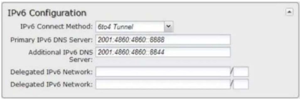
6in4 Tunnel
The 6in4 tunnel mode utilizes explicit IPv4 tunnel endpoints and encapsulates IPv6 packets using 41 as the specified protocol type in the IP header. A 6in4 tunnel broker provides a static IPv4 server endpoint, decapsulates packets, and provides routing for both egress and ingress IPv6 packets. Most tunnel brokers provide a facility to request delegated networks for use through the tunnel.
- Tunnel Server IP – Input the tunnel server IP address provided by your tunnel service.
- Local IPv6 Address – Input the local IPv6 address provided by your tunnel service.
- Primary IPv6 DNS Server – (optional) Depending on your provider, this may be required. This only takes effect if the default global DNS setting on the Network Settings → DNS page is "Automatic".
• Additional IPv6 DNS Server – Secondary DNS server. - Delegated IPv6 Network – (optional) Network available for delegation to LANs. Depending on your provider, this may be required. Prefixes specified here only take effect if those supplied by the connection are insufficient to configure your LANs.
- Delegated IPv6 Network – Additional network available for delegation to LANs.
Example Configuration:
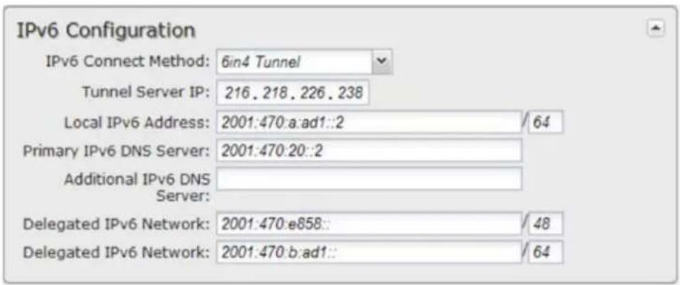
6rd Tunnel
IPv6 Rapid Deployment (6rd) is a method of IPv6 site configuration derived from 6to4. It is different from 6to4 in that the ISP provides explicit 6rd infrastructure that handles the IPv4 ↔ IPv6 translation within the ISP network. 6rd is considered more reliable than 6to4 as the ISP explicitly maintains infrastructure to support tunneled IPv6 traffic over their IPv4 network.
- 6rd Prefix – The 6rd prefix and prefix length should be supplied by your ISP.
- IPv4 Border Router Address – This address should be supplied by your ISP.
- IPv4 Common Prefix Mask – Input the number of common prefix bits that you can mask off of the WAN's IPv4 address.
- Primary IPv6 DNS Server – (optional) Depending on your provider, this may be required. This only takes effect if the default global DNS setting on the Network Settings → DNS page is "Automatic".
• Additional IPv6 DNS Server – Secondary DNS server. - Delegated IPv6 Network – (optional) Network available for delegation to LANs. Depending on your provider, this may be required. Prefixes specified here only take effect if those supplied by the connection are insufficient to configure your LANs.
- Delegated IPv6 Network – Additional network available for delegation to LANs.
Example Configuration:
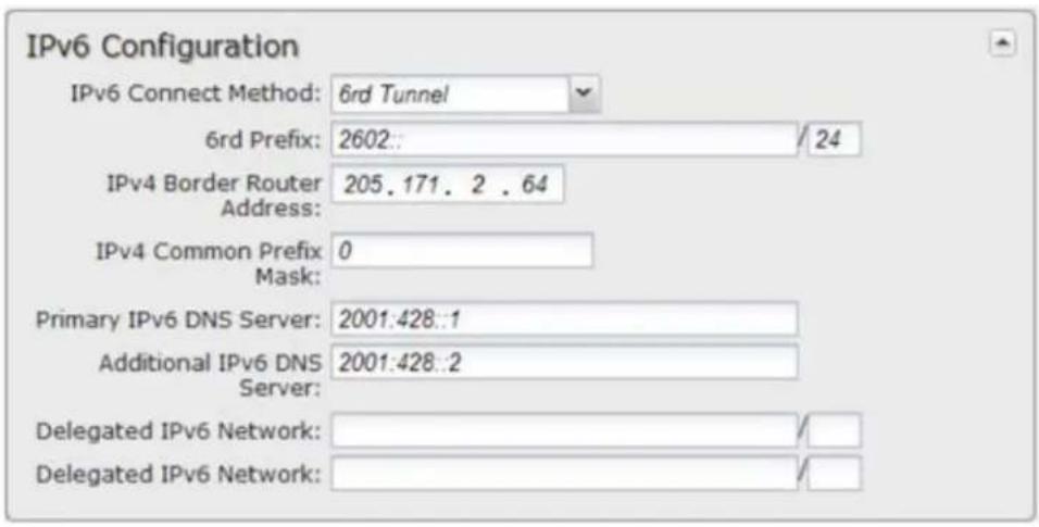
Ethernet Settings
While default settings for each WAN Ethernet port will be sufficient in most circumstances, you have the ability to control the following:
- Connect Method: DHCP (Automatic), Static (Manual), or PPPoE (Point-to-Point Protocol over Ethernet).
- MAC Address: You have the ability to change the MAC address, but typically this is unnecessary. You can match this address with your device's address by clicking: "Clone Your PC's MAC Address".
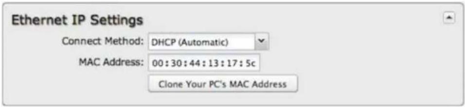
Connect Method
Select the connection type that you need for this WAN connection. You may need to check with your ISP or system administrator for this information.
- DHCP (Dynamic Host Configuration Protocol) is the most common configuration. Your router's Ethernet ports are automatically configured for DHCP connection. DHCP automatically assigns dynamic IP addresses to devices in your networks. This is preferable in most circumstances.
- Static allows you to input a specific IP address for your WAN connection; this should be provided by the ISP if supported.
- PPPoE should be configured with the username, password, and other settings provided by your ISP.
If you want to use a Static (Manual) or PPPoE connection, you will need to fill out additional information.
Static (Manual)
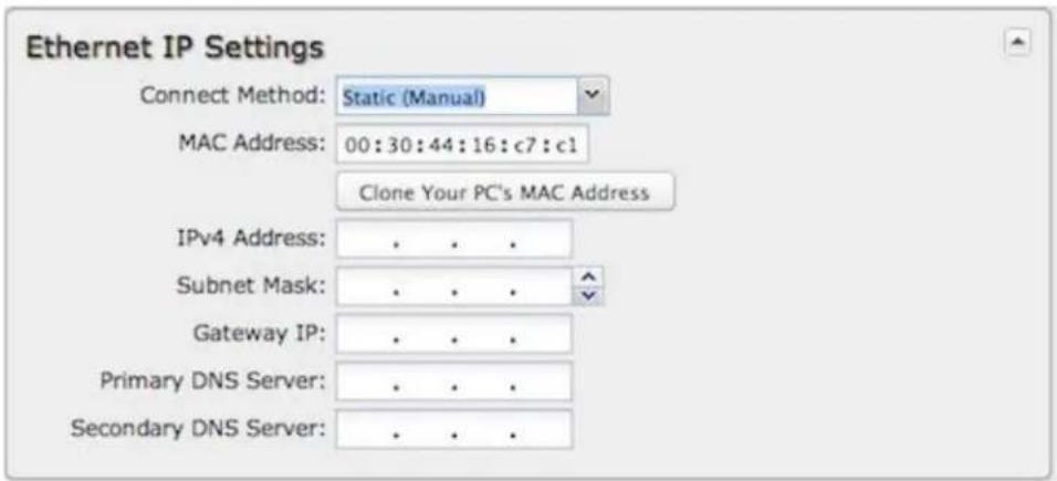
- IPv4 Address
- Subnet Mask
- Gateway IP
- Primary DNS Server
• Secondary DNS Server
PPPoE:

- Username
- Password
- Password Confirm
• Service
• Auth Type: None, PAP, or CHAP
Modem Settings
Not all modems will have all of the options shown below; the available options are specific to the modem type.
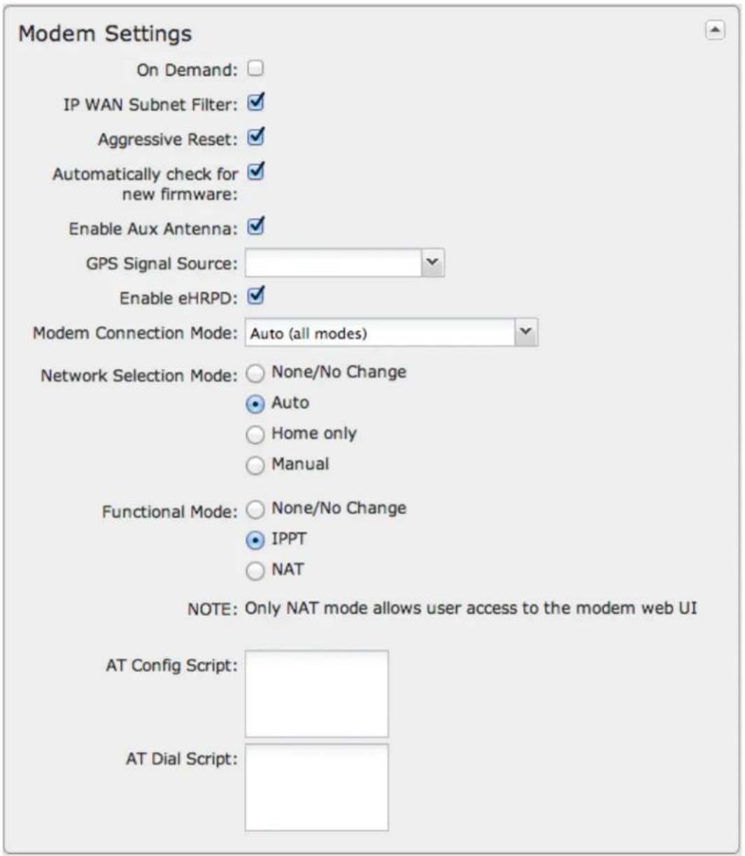
On Demand: When this mode is selected a connection to the Internet is made as needed. When this mode is not selected a connection to the Internet is always maintained.
IP WAN Subnet Filter: This feature will filter out any packets going to the modem that do not match the network (address and netmask).
Aggressive Reset: When Aggressive Reset is enabled the system will attempt to maintain a good modem connection. If the Internet has been unreachable for a period of time, a reset of the modem will occur in attempt to re-establish the connection.
Automatically check for new firmware. (Default: selected) The modem will automatically check for firmware updates by default.
Enable Aux Antenna: (Default: selected) Enable or disable the modem's auxiliary diversity antenna. This should normally be left enabled.
GPS Signal Source: Select the antenna to be used for receiving GPS coordinates. Some products support a dedicated GPS antenna, while others use the auxiliary diversity antenna only (and some products support both).
Enable eHRPD: (Default: selected) Enable or disable the modem's ability to connect via eHRPD (enhanced High Rate Packet Data) when connecting to a 3G EVDO network on Sprint. eHRPD routes EVDO traffic through the LTE systems, enabling easy transitions between LTE and EVDO. In rare cases it may make sense to bypass the LTE core, so this field allows you to disable eHRPD.
Modem Connection Mode: Specify how the modem should connect to the network. Not all options are available for all modems; this will default to Auto if an incompatible mode is selected.
• Auto (all modes): Let the modem decide which network to use.
• Auto 3G (3G or less): Let the modem decide which 2G or 3G network to use. Do not attempt to connect to LTE.
• Force LTE: Connect to LTE only and do not attempt to connect to 3G or WiMAX.
• Force WiMAX: Connect to WiMAX only and do not attempt to connect tot 3G or LTE.
• Force 3G (EVDO, UMTS, HSPA): Connect to 3G network only.
• Force 2G (1xRTT, EDGE, GPRS): Connect to 2G network only.
Network Selection Mode: Wireless carriers are assigned unique network identifying codes known as PLMN (Public Land Mobile Network). To manually select a particular carrier, select the Manual radio button and enter the network PLMN. Choose from the following options:
- None/No Change
• Auto: Selected by default - Home only
• Manual: Input the PLMN code
Functional Mode: Selects the functional mode of the modem. IPPT (IP passthrough) mode causes the modem to act as a transport, passing Internet data and IP address information between the modem and the Internet directly. NAT mode causes the modem to NAT the IP address information. Consequently, IPPT mode does not allow user access to the modem web UI and NAT mode does allow user access to the modem web UI.
- None/No Change
• IPPT
• NAT
Network-Initiated Alerts: This field controls whether the Sprint network can disconnect the modem to apply updates, such as for PRL, modem firmware, or configuration events. These activities do not change any router settings, but the modem connection may be unavailable for periods of time while these updates occur. The modem may also require a reset after a modem firmware update is complete.
• Disabled: The request to update will be refused.
- When Disconnected: The request to update will only be performed when the modem is either in a disconnected state or dormant state. If the modem is not in one of these states when the request is received, then the router will remember the request and perform the update when the modem becomes disconnected/dormant.
- On Schedule: The request to update will only be performed at the specified scheduled time, no matter what the state of the modem is.
Network-Initiated Schedule: When you select "On Schedule" for Network-Initiated Alerts, you also select a time from this dropdown list. Modem updates will take place at this scheduled time.
AT Config Script: Enter the AT commands to be used for carrier specific modem configuration settings. Each command must be entered on a separate line. The command and associated response will be logged, so you should check the system log to make sure there were no errors.
NOTE: AT Config Script should not be used unless told to do so by your modem's cellular provider or by a support technician.
AT Dial Script: Enter the AT commands to be used in establishing a network connection. Each command must be entered on a separate line. All command responses must include "OK", except the final command response, which must include "CONNECT".
Example:
AT ATDT*99***2#
WiMAX Settings
WiMAX Realm: Select from the following dropdown options:
- Clear – clearwire-wmx.net
- Rover – rover-wmx.net
- Sprint 3G/4G – sprintpcs.com
• Xohm -xohm.com
• BridgeMAXX – bridgeMAXX.com
• Time Warner Cable – mobile.rr.com
- Comcast – mob.comcast.net
TTLS Authentication Mode: TTLS inner authentication protocol. Select from the following dropdown options:
• MSCHAPv2/MD5 (Microsoft Challenge Handshake Authentication Protocol version2/Message-Digest Algorithm 5)
• PAP (Password Authentication Protocol)
• CHAP (Challenge Handshake Authentication Protocol)
TTLS Username: Username for TTLS authentication.
TTLS Password: Password for TTLS authentication.
WiMAX Authentication Identity: User ID on the network. Leave this blank unless your provider tells you otherwise.
CDMA Settings
These settings are usually specific to your wireless carrier's private networks. You should not set these unless directed to by a carrier representative. If a field below is left blank, that particular setting will not be changed in the modem. You should only fill in fields that are required by your carrier.
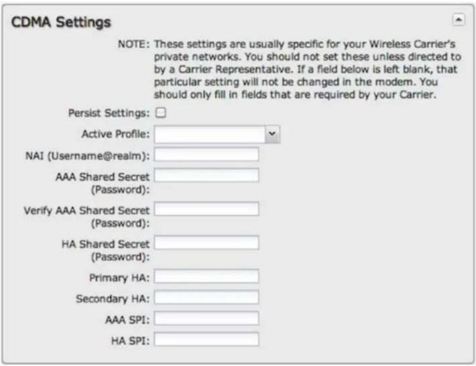
- Persist Settings: If this is not checked, these settings will only be in place until the router is rebooted or the modem is unplugged.
• Active Profile: Select a number from 0-5 from the dropdown list.
The following fields can be left blank. If left blank they will remain unchanged in the modem.
• NAI (Username@realm): Network Access Identifier, NAI is a standard system of identifying users who attempt to connect to a network.
- AAA Shared Secret (Password): "Authentication, Authorization, and Accounting" password.
• Verify AAA Shared Secret
• HA Shared Secret: "Home Agent" shared secret.
- Primary HA
• Secondary HA
• AAA SPI: AAA Security Parameter Index.
• HA SPI: HA Security Parameter Index.
SIM/APN/Auth Settings
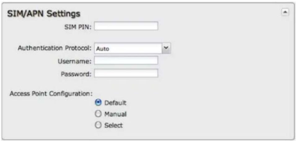
SIM PIN: PIN number for a GSM modem with a locked SIM.
Authentication Protocol: Set this only if your service provider requires a specific protocol and the Auto option chooses the wrong one. Choose from Auto, PAP, and CHAP and then input your username and password.
Access Point Configuration: Some wireless carriers provide multiple Access Point configurations that a modem can connect to. Some APN examples are "isp.cingular" and "vpn.com".
- Default: Let the router choose an APN automatically.
- Default Override: Enter an APN by hand.
- Select: This opens a table with 16 slots for APNs, each of which can be set as IP, IPV4V6, or IPV6. The default APN is marked with an asterisk (*). You can change the APN names, select a different APN, etc. For Verizon modems, only the third slot is editable. Changes made here are written to the modem, so a factory reset of the router will not impact these settings.
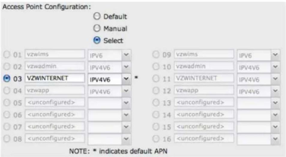
Update/Activate a Modem
Some 3G/4G modems can be updated and activated while plugged into the router. Updates and activation methods vary by modem model and service provider. Possible methods are: PRL Update, Activation, and FUMO. All supported methods will be displayed when you select your modem and click "Control" to open the "Update/Activate" window. If no methods are displayed for your device then you will need to update and activate your device externally.
To update or activate a modem, select the modem in the WAN Interfaces table and click "Control".
The modem does not support Update/Activate methods: A message will state that there is no support for PRL Update, Activation, or FUMO.
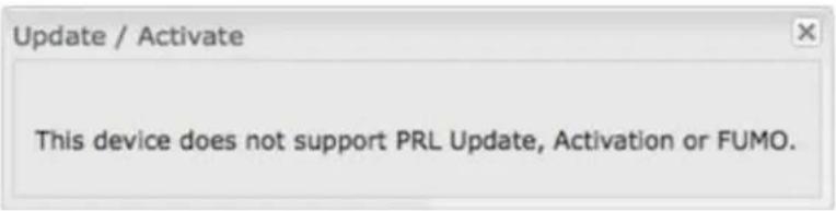
The modem supports Update/Activate methods: A message will display showing options for each supported method:
- Modem Activation / Update: Activate, Reactivate, or Upgrade Configuration.
• Preferred Roaming List (PRL) Update
• Firmware Update Management Object (FUMO)
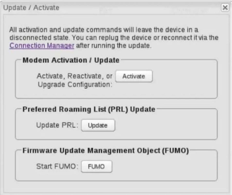
Click the appropriate icon to start the process.
If the modem is connected when you start an operation the router will automatically disconnect it. The router may start another modem as a failover measure. When the operation is done the modem will go back to an idle state, at which point the router may restart it depending on failover and failback settings.
NOTE: Only one operation is supported at a time. If you try to start the same operation on the same modem twice the UI will not report failure and the request will finish normally when the original request is done. However if you try to start a different operation or use a different modem, this second request will fail without interfering with the pending operation.
Process Timeout: If the process fails an error message will display.

Activation has a 3-minute timeout, PRL update has a 4-minute timeout, and FUMO has a 10-minute timeout.
Update Modem Firmware
Click on the Firmware button to open the Modem Firmware Upgrade window. This will show whether there is new modem firmware available.
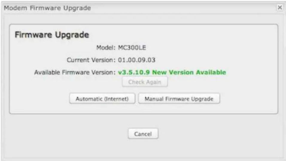
If you select Automatic (Internet) the firmware will be updated automatically. Use Manual Firmware Upgrade to instead manually upload firmware from a local computer or device.
Reset the Modem
Click on the Reset button to power cycle the modem. This will have the same effect as unplugging the modem.
Configuration Rules (Advanced)
This section allows you to create general rules that apply to the Internet connections of a particular type. These can be general or very specific. For example, you could create a rule that applies to all 3G/4G modems, or a rule that only applies to an Internet source with a particular MAC address.
The Configuration Rules list shows all rules that you have created, as well as all of the default rules. These are listed in the order they will be applied. The most general rules are listed at the top, and the most specific rules are at the bottom. The router goes down the list and applies all rules that fit for attached Internet sources. Configuration settings farther down the list will override previous settings.
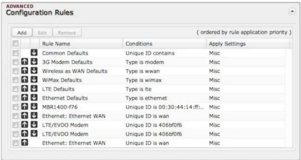
Select any of these rules and click "Edit" to change the settings for a rule. To create a new rule, click "Add."
WAN Configuration Rule Editor
After clicking "Add" or "Edit," you will see a popup with the following tabs:
- Filter Criteria
- General Settings
IP Overrides - IPv6 Settings
- Ethernet Settings
- Modem Settings
- WiMAX Settings
- CDMA Settings
• SIM/APN/Auth Settings
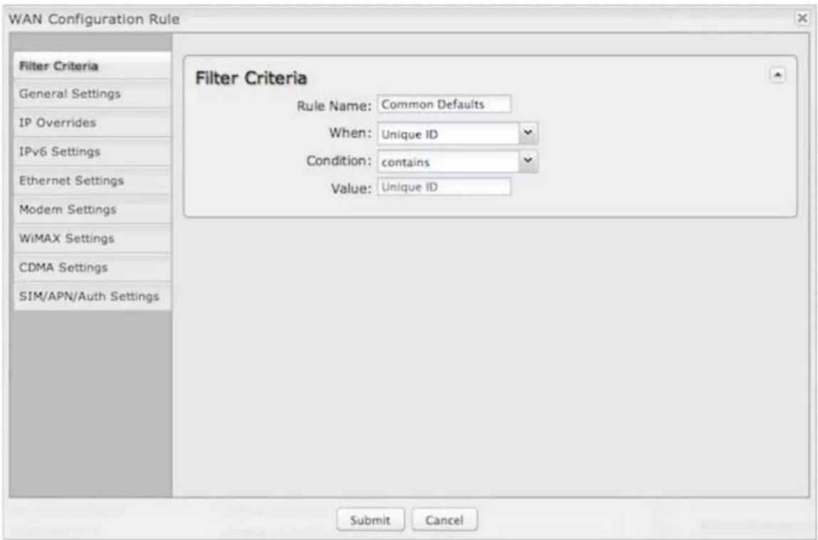
Filter Criteria
If you are creating a new rule, begin by setting the Filter Criteria. Create a name for your rule and the condition for which the rule applies:
- Rule Name: Create a name meaningful to you. This name is optional.
Make a selection for "When," "Condition," and "Value" to create a condition for your rule. The condition will be in the form of these examples:
| When Condition Value | |
| Port is USB Port 1 | |
| Type is not WiMAX | |
- When
- Port – Select by the physical port on the router that you are plugging the modem into (e.g., "USB Port 2").
- Manufacturer – Select by the modem manufacturer, such as Sierra Wireless.
- Model – Set your rule according to the specific model of modem.
- Type – Select by type of Internet source (Ethernet, LTE, Modem, Wireless as WAN, WiMAX).
-
Serial Number – Select 3G or LTE modem by the serial number.
-
MAC Address – Select WIMAX modem by MAC Address.
- Unique ID – Select by ID. This is generated by the router and displayed when the device is connected to the router.
- Condition: Select "is," "is not," "starts with," "contains," or "ends with" to create your condition's statement.
- Value: If the correct values are available, select from the dropdown list. You may need to manually input the value.
Once you have established the condition for your configuration rule, choose from the other tabs to set the desired configuration. All of the tabs have the same configuration options shown above in the WAN Configuration section (i.e., the options for Configuration Rules are the same as they are for individual devices).
Client Data Usage
Client Data Usage displays upload and download traffic for each LAN client. Click Enable Client Data Usage Monitoring Service to begin tracking this information. This data is not retained between router reboots.
| Client Data Usage | |||||
| Reset Statistics | |||||
| Name ▲ | IP | MAC | Uploaded | Downloaded | Last Traffic |
| jcramer-osx | 192.168.0.87 | e4:ce:8f:13:f3:bc | 31434.45 MB | 1407.52 MB | 11/14 12:4 |
For each client this shows: Name, IP address, MAC address, amount of data uploaded (MB), amount of data downloaded (MB), and when traffic was last sent or received for that client ("Last Traffic").
The names that are shown are received during a DHCP exchange. If a client disconnects and reconnects with a new IP address there will be an additional entry in this list.
Pressing Reset Statistics will restart all counters at 0.
Data Usage
Data Usage Management & Alerts allows you to create and manage rules that help control the data usage of a modem. If you have a limited data plan or a price increase on your plan after a certain amount of usage, a Data Usage Rule can help you track these amounts. You can set a rule to shut down use of a modem and/or send a message when you reach a data usage amount you set.
When you select Enable Data Usage, you will see the Data Usage Agreement shown below. The purpose of this agreement is to ensure that you understand that the data numbers for your router might not perfectly match those of your carrier: CradlePoint cannot be held responsible. You must accept the agreement by clicking "Yes" in order to begin creating data usage rules.
Warning: You should set your data limits lower than your carrier data allowance and regularly compare the numbers provided by the router with the numbers from your carrier.
Data Usage Rules
The Date Usage Rule display shows basic information for each rule you have created (including rules created with a template). The following information is displayed:
- Rule Name
- Enabled: True/False
- Date for Rule Reset
• Cycle Type: Daily, Weekly, or Monthly - Cap: Amount in MB.
- Current Usage: Shown as an amount in MB, as a percentage of the cap, and in a bar graph.
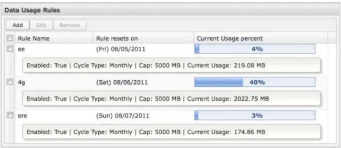
Click Add to configure a new Data Usage Rule.
Data Usage Rule – page 1
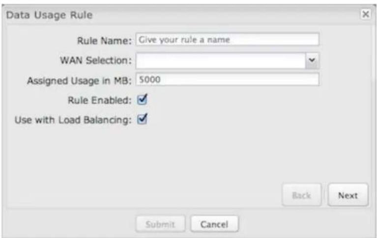
Rule Name: Give your rule a name for later recognition.
WAN Selection: Select from the dropdown list of currently attached WAN devices.
Assigned Usage in MB: Enter a cap amount in megabytes. 1024 megabytes equals 1 gigabyte.
Rule Enabled: (Default: Enabled.) Click to disable.
Use with Load Balancing: When checked, the Load Balancing feature is allowed to use the thresholds and metrics of this rule when making balance decisions. This causes Load Balancing to spread the data usage between interfaces according to the assigned usage rather than bandwidth. This is a best effort to keep all interfaces with these rules at a similar percentage utilization of data (e.g., 10%, 50%, 90%) as the cycle progresses, rather than quickly using 100% of a fast 1 GB capped interface while using only a fraction of a slow 10 GB capped interface, thus leaving the rest of the cycle with only the slow interface. To use this setting, you must also go to the Internet → WAN Affinity / Load Balancing page. For the Load Balance Algorithm field select "Data Usage".
Data Usage Rule – page 2
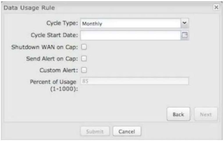
Cycle Type: How often the rule will reset. The data usage amount will be reset at the end of each cycle. Select the length of a cycle from a dropdown menu with the following choices:
• Daily
• Weekly
• Monthly
Cycle Start Date: Select the date you wish the rule to begin. This date will be used to track when the rule will reset.

Shutdown WAN on Cap: If selected, the WAN device will shut down when the assigned usage is reached. A cycle reset or a rule deletion will re-enable the device.
Send Alert on Cap: An email alert will be generated and sent when the assigned usage is reached.
WARNING: The SMTP mail server must be configured in System Settings → Device Alerts
Custom Alert: When checked you enable a second email to be configured for a percentage of the assigned usage.
Percent of Usage (1-1000): If selected, a custom alert will be sent when your data usage reaches this percentage of your usage cap. For example, you could set this at 90 percent so that you know when your usage is nearing 100 percent of the cap.
Template Configuration
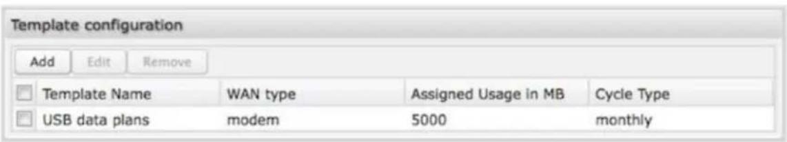
Templates allow you to control multiple WAN devices with the same rule. Each WAN device that matches a template will automatically have its own rule created.
For example, you can set a template rule for all mobile data modems that causes your router to send an alert after 1000 MB of usage in a month. When you attach a new 4G USB modem, your template will immediately create a new Data Usage Rule for the attached modem that sends the alert as specified.
Click Add to configure a new Template rule.
Create a Template Name that you can recognize. The template will apply to one of the following WAN types:
All WAN
• All Ethernet
• All Modems
Select one of these types.
The rest of the rule settings options match those in the Data Usage Rules. See the section above for additional information about how to configure your template usage rules.
Historical Data
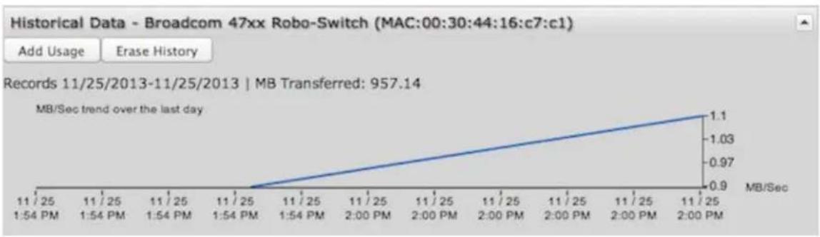
line
| Time Period | MB/Sec | | ----------------- | ------ | | 11/25 1:54 PM | 0.9 | | 11/25 1:54 PM | 0.97 | | 11/25 1:54 PM | 1.03 | | 11/25 2:00 PM | 1.1 | | 11/25 2:00 PM | 1.03 | | 11/25 2:00 PM | 0.97 | | 11/25 2:00 PM | 0.9 |The Historical Data graph displays if you have a Data Usage Rule enabled for an active WAN device. This graph shows the MB/sec trend for the last day. In this section you also have the ability to change the data usage records for a connected WAN device: Add Usage or Erase History. You may want to add data usage to a device's record if, for example, you've used the SIM or data plan with other devices — that data usage wouldn't otherwise be recorded by the router.
Click on Add Usage and then select the date and input additional data amount in MB.
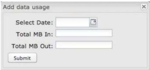
GRE Tunnels
Generic Routing Encapsulation (GRE) tunnels can be used to create a connection between two private networks. Most CradlePoint routers are enabled for both GRE and VPN tunnels. GRE tunnels are simpler to configure and more flexible for different kinds of packet exchanges, but VPN tunnels are much more secure.
| GRE Tunnels | |||||||
| Add Edit Remove | |||||||
| Name | Local Network | Remote Network | Remote Gateway | Routes | Keep Alive | Enabled | |
| office_tunnel | 10.1.1.1 255.255.255.0 | 10.1.1.2 255.255.255.0 | 172.22.22.1 | 1 | Yes | Yes | |
In order to set up a tunnel you must configure the following:
- Local Network and Remote Network addresses for the "Glue Network," the network that is created by the administrator that serves as the "glue" between the networks of the tunnel. Each address must be a different IP address from the same private network, and these addresses together form the endpoints of the tunnel.
- Remote Gateway, the public facing WAN IP address that the local gateway is going to connect to.
- Routes that allow you to configure what network traffic from local host(s) will be allowed through the tunnel.
- Optionally, you might also want to enable the tunnel Keep Alive feature to monitor the status of a tunnel and more accurately determine if the tunnel is alive or not.
Optionally, you might also want to enable the tunnel Keep Alive feature to monitor the status of a tunnel and more accurately determine if the tunnel is alive or not.
Click Add to configure a new GRE tunnel; click Edit to make changes to an existing tunnel.
Add/Edit Tunnel – General
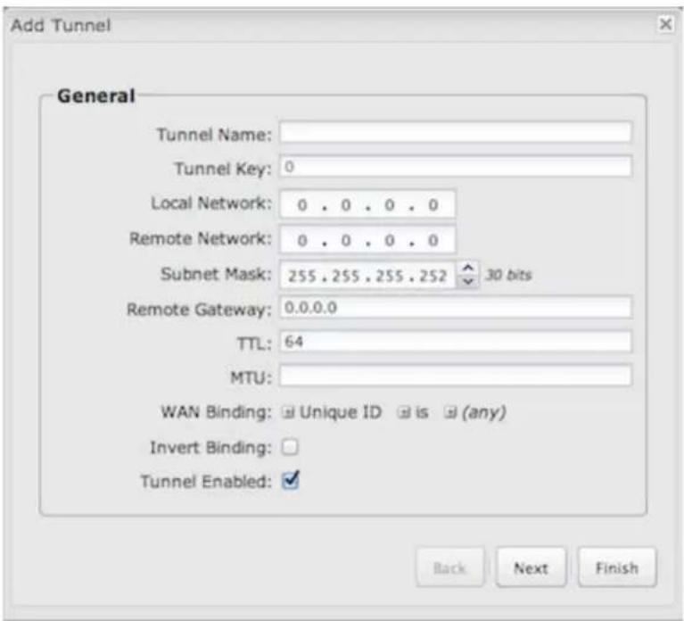
Tunnel Name: Give the tunnel a name that uniquely identifies it.
Tunnel Key: Enables an ID key for a GRE tunnel, which can be used as an identifier for mGRE (Multipoint GRE).
Local Network: This is the local side of the "Glue Network," a network created by the administrator to form the tunnel. The user creates the IP address inputted here. It must be different from the IP addresses of the networks it is gluing together. Choose any private IP address from the following three ranges that doesn't match either network:
10.0.0.0 - 10.255.255.255
• 172.16.0.0 - 172.31.255.255
• 192.168.0.0 - 192.168.255.255
Remote Network: This is the remote side of the "Glue Network." Again, the user must create an IP address that is distinct from the IP addresses of the networks that are being glued together. The Remote Network and Local Network values will be flipped when inputted for the other side of the tunnel configuration.
Subnet Mask: This is the subnet mask for the Glue Network. The Local and Remote Network addresses must fit with this mask. 255.255.255.0 is a logical choice for most users.
Remote Gateway: This is the public facing, WAN-side IP address of the network that the local gateway is going to connect to.
TTL. Set the Time to Live (TTL), or hop limit, for the GRE tunnel.
MTU: Set the maximum transmission unit (MTU) for the GRE tunnel.
WAN Binding: WAN Binding is an optional parameter used to configure the GRE tunnel to ONLY operate when the specified WAN device(s) are available and connected. An
example use case is when there is a router with both a primary and failover WAN device and the tunnel should only be used when the system has failed over to the backup connection.
Make a selection for "When," "Condition," and "Value" to create a WAN Binding. The condition will be in the form of these examples:
| When Condition Value | |
| Port is USB Port 1 | |
| Type is not WiMAX |
- When:
- Port – Select by the physical port on the router that you are plugging the modem into (e.g., "USB Port 2").
- Manufacturer – Select by the modem manufacturer (e.g., "CradlePoint Inc.).
- Model – Set your rule according to the specific model of modem.
- Type – Select by type of Internet source (Ethernet, LTE, Modem, Wireless as WAN, WiMAX).
- Serial Number – Select a 3G or LTE modem by the serial number.
- MAC Address – Select a WIMAX modern by MAC Address.
-
Unique ID – Select by ID. This is generated by the router and displayed when the device is connected to the router.
-
Condition. Select "is," "is not," "starts with," "contains," or "ends with" to create your condition's statement.
• Value: If the correct values are available, select from the dropdown list. You may need to manually input the value.
Invert WAN Binding: Advanced option that inverts the meaning of WAN Binding to only establish this tunnel when the specified WAN Binding device(s) are NOT connected.
Tunnel Enabled: Select to activate the tunnel.
Add/Edit Tunnel – Routes
Adding routes allows you to configure what types of network traffic from the local host or hosts will be allowed through the tunnel.
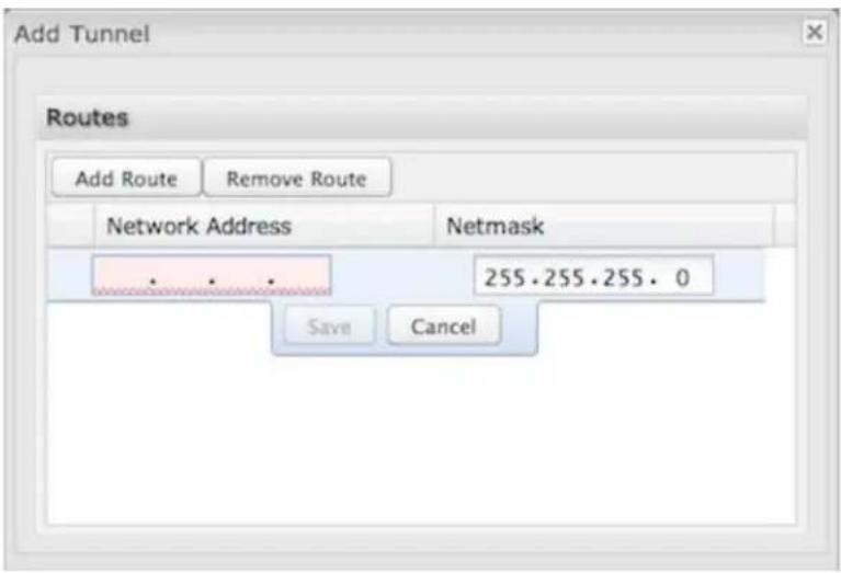
Click Add Route to configure a new route. You will need to input the following information, defined by the remote network:
• Network Address – This is the network address that is the destination of the route. This should be set to the network address at the remote side of the tunnel.
- Netmask – This is the corresponding subnet mask of the network being defined (Default: 255,255,255.0).
You can set the tunnel to connect to a range of IP addresses or to a single IP address. For example, you could input 192.168.0.0 and 255.255.255.0 to connect your tunnel to all the addresses of the remote network in the 192.168.0.x range. Alternatively, you could select a single address by inputting that address along with a Netmask of 255.255.255.255.
Add/Edit Tunnel – Keep Alive
GRE keep-alive packets can be enabled to be sent through the tunnel in order to monitor the status of the tunnel and more accurately determine if the tunnel is alive or not.
GRE keep-alive packets may be sent from both sides of a tunnel, or from just one side.
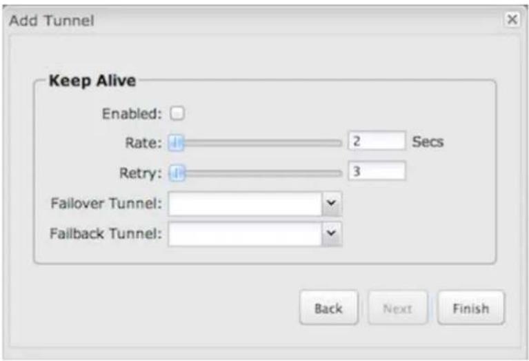
Enabled: Select to enable GRE Keep Alive to continually send keep alive packets to the remote peer.
Rate: Choose the length of time in seconds for each check (Default: 10 seconds. Range: 2 - 3600 seconds).
Retry: Select the number of attempts before the GRE tunnel is considered down or up (Default: 3. Range: 1 - 255).
Failover Tunnel and Failback Tunnel: Use these settings to create two tunnels – one as the primary tunnel and one as the backup tunnel. To configure tunnel failover/failback, complete the following steps:
- Create two tunnels: one for primary and one for backup. Make sure both tunnels have Keep Alive enabled.
- Choose one to be the primary tunnel. Open the editor for this tunnel and make sure Tunnel Enabled is selected. Then go to the Keep Alive page. Under Failover Tunnel select the other tunnel you have created.
- Open the editor for the falover tunnel. Make sure Tunnel Enabled is not selected. On the Keep Alive page, set the Failback Tunnel to your primary tunnel.
L2TP Tunnels
NOTE: L2TP Tunnels require a feature license. Go to System Settings → Feature Licenses to enable this feature.
Layer 2 Tunneling Protocol (L2TP) tunnels can be used to create a connection between two private networks.
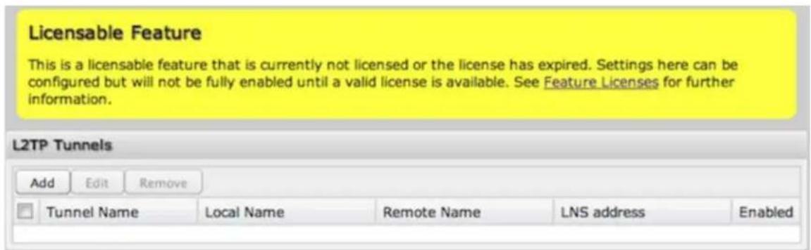
Once you have a valid feature license, click Add to create a new L2TP tunnel. Click Edit to make changes to an existing tunnel.
Add/Edit Tunnel – General
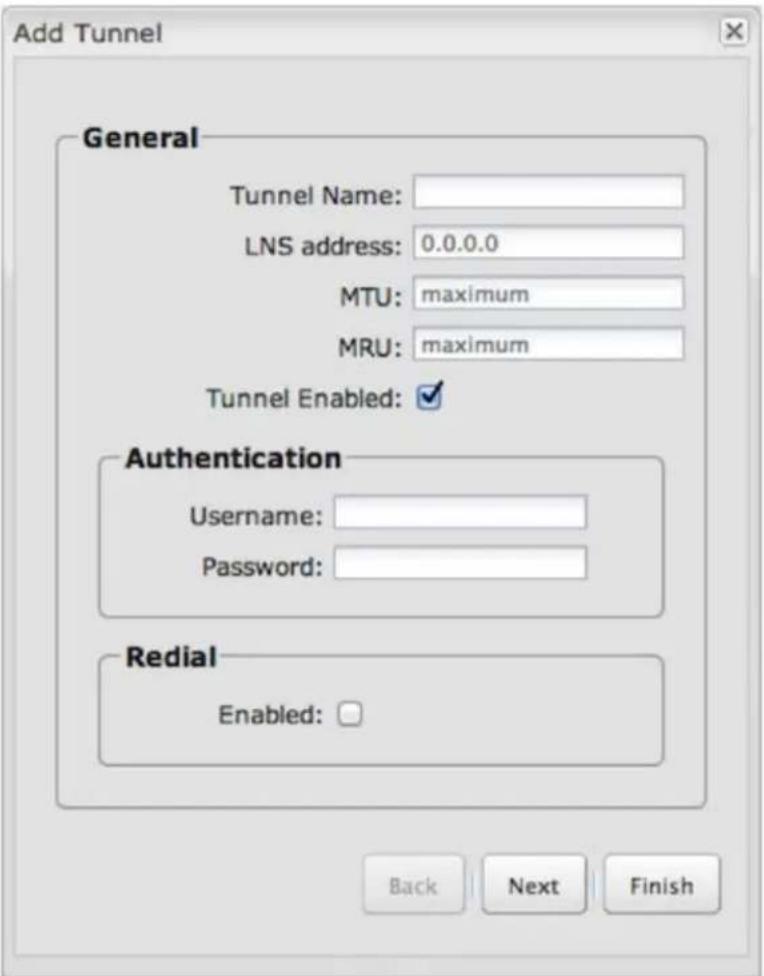
- Tunnel Name – Enter a name to uniquely identify this tunnel.
• LNS address – Enter the IP Address of the LNS (tunnel server) peer. - MTU – Set the maximum transmission unit (MTU) for the L2TP tunnel.
- MRU – Set the maximum receive unit (MRU) to request from the tunnel peer. The MRU is very similar to the MTU: MTU is for packets sent and MRU is for packets received.
- Tunnel Enabled – Click to enable/disable this tunnel. Default: Enabled.
Authentication
More authentication options and overrides are available in the next section.
- Username – Username for user-specific authorization. Leave blank to disable.
- Password – Shared secret (or password) used to authenticate the associated Local and Remote names.
Redial
- Enabled – When this is selected, the tunnel will attempt to reconnect if disconnected.
Add/Edit Tunnel – Authentication
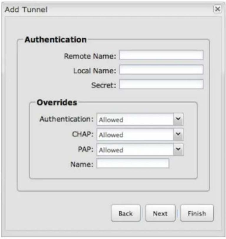
- Remote Name – Authorization name specified by and to the remote system as its identity, sometimes a username or hostname. Leave blank to match any.
- Local Name – Authorization name specified by and to the remote system as the local system identity; sometimes a username or hostname. Leave blank to match any.
- Secret – Shared secret (or password) used to authenticate the associated Local and Remote names.
Overrides
Override Authentication methods/parameters. With methods set to Allow the two ends of the tunnel can negotiate a common scheme. Sometimes this negotiation fails, or the implementation on one end is incompatible with the other. To solve those authentication issues, enable the overrides as needed.
- Authentication – Username for user-specific authorization. Leave blank to disable.
• CHAP – Choose from Allowed, Refused, or Required.
• PAP — Choose from Allowed, Refused, or Required. - Name – Override names used to authenticate the router. Leave empty to use the default.
Add/Edit Tunnel – Routes
Typically specific routes are unnecessary, but they can be added in this section if needed. You can add or remove routes to be used to funnel packets through the tunnel.
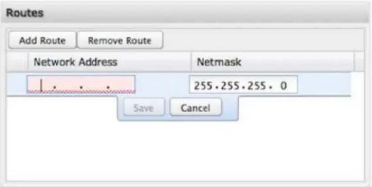
• Network Address – This is the network address that is the destination of the route. This should be set to the network address at the remote side of the tunnel.
- Netmask – This is the corresponding subnet mask of the network being defined.
Network Mobility (NEMO)
NOTE: NEMO requires a feature license. Go to System Settings → Feature Licenses to enable this feature.
Network Mobility (NEMO) is an Internet standards track protocol defined in RFC 5177. The protocol allows session continuity for every node in a mobile network as the network moves.
NEMO requires a service provider, e.g. Verizon Wireless Private Network with DMNR (Dynamic Mobile Network Routing). Your NEMO service provider will define many of the settings for your NEMO configuration.
Once you have a NEMO service provider and a valid feature license, add networks to the Networks Routed by NEMO section by first clicking Add. In the popup window, input:
- Network Address
- Netmask
The Network Address and Netmask, or subnet mask, together define a range of IP addresses that comprise the local network you want associated with the NEMO settings.
Internet / NEMO
Licensed Feature
Feature expires in 14 days. See Feature Licenses for further information.
Networks Routed by NEMO
Add
EOR
Remove

Network Address
Netmask
Local Network Name

192.168.52.1
255.255.255.0
NeMo
Network Mobility (NEMO) Settings
Enabled: √
Home IP Address:
1.2.3.4
Home Netmask:
255.255.255.255

32 bits
Home Agent IP Address:
66.174.252.2
Home Agent Password:
VzWNeMo
Home Agent SPI:
256
Renew Registration:
30
MTU:
Apply
Undo
Network Mobility (NEMO) Settings
Home IP Address and Home Netmask – These may be provided by your NEMO service provider. The IP address is a placeholder, "dummy" address; any IP address can be used (1.2.3.4 is common).
Home Agent IP Address, Home Agent Password, and Home Agent SPI – Your home agent will be defined by your NEMO service provider.
Renew Registration – The NEMO network regularly re-registers with the home agent (e.g., every 30 seconds). Specify the number of seconds between each check-in.
MTU – Override the maximum transmission unit (MTU) of the NEMO tunnel. The TCP MSS (maximum segment size) is automatically derived from the MTU. Leave blank to rely on Path MTU Discovery.
NHRP Interfaces
NOTE: NHRP Configuration requires a feature license. Go to System Settings → Feature Licenses to enable this feature.
Next Hop Resolution Protocol is a protocol used to discover addresses of clients on Non-Broadcast Multiple Access (NBMA) networks. It is used to create next-generation VPN technologies that allow shortcutting between spokes. With NHRP, systems attached to an NBMA network dynamically learn the NBMA address of the other systems that are part of that network, allowing these systems to directly communicate without requiring an intermediate hop.
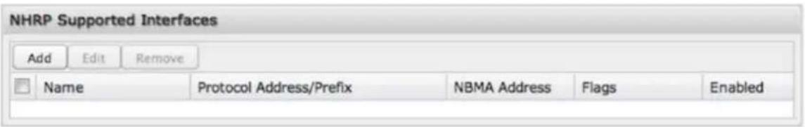
The NHRP Supported Interfaces table displays the following fields for each configured NHRP interface.
• Name: Name of the GRE tunnel that NHRP will use.
- Protocol Address/Prefix: GRE tunnel endpoint mapping that NHRP associates with the NBMA server.
• NBMA Address: NBMA server address the protocol address/prefix is associated with.
- Flags
- SD: Shortcut-Destination
- N: Non-Caching
- S: Shortcut
- R: Redirect Click Add to create a new NHRP interface.
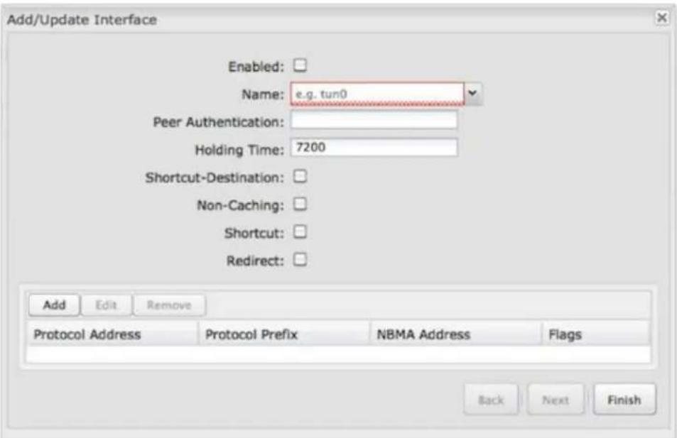
• Enabled: Enable or disable the interface
- Name: Give the interface a unique name that matches the mGRE (multipoint GRE) tunnel. Select from configured GRE tunnels or input manually.
- Peer Authentication: Embeds the secret plaintext password to outgoing NHRP packets. Incoming NHRP packets on this interface are discarded unless this password is present. Max length: 8 characters.
- Holding Time: Specifies the holding time for NHRP registration requests and resolution replies.
- Shortcut-Destination: Reply with authoritative answers on NHRP resolution requests destined to addresses in this interface (instead of forwarding the packets).
• Non-Caching: Disables caching of peer information from forwarded NHRP resolution reply packets.
- Shortcut: Enable creation of shortcut routes.
- Redirect: Enable sending of proprietary enterprise-style NHRP traffic indication packets.
You also have the option to create static mappings for this interface. Click Add in the table to open the static mapping editor.
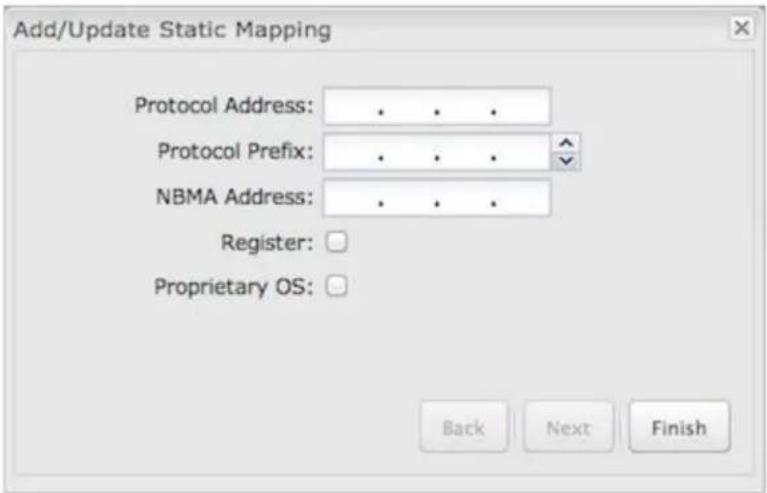
- Protocol Address: Mapped endpoint to from protocol address to NBMA address.
- Protocol Prefix: Optional prefix for protocol address.
• NBMA Address: Destination mapped address from protocol address/prefix. - Register: This optional parameter specifies that a Registration Request should be sent to this peer on startup (displays flag R in the static mapping table if selected).
- Proprietary OS: This should be enabled if the statically mapped peer is running proprietary OS (displays flag C in the static mapping table if selected).
OpenVPN Tunnels
NOTE: OpenVPN requires a feature license. Go to System Settings → Feature Licenses to enable this feature.
OpenVPN is an open source software application that implements virtual private network (VPN) techniques for creating secure point-to-point or site-to-site connections in routed or bridged configurations and remote access facilities.
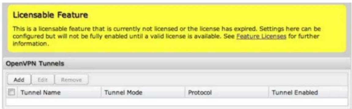
Once you have a valid feature license, click Add to create a new OpenVPN tunnel. Click Edit to make changes to an existing tunnel.
Add/Edit Tunnel – General
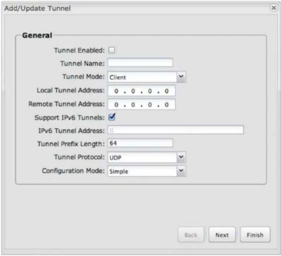
- Tunnel Enabled – Click to enable/disable this tunnel.
- Tunnel Name – Enter a name to uniquely identify this tunnel.
- Tunnel Mode – Select which mode this tunnel endpoint is required to be. Choose from the following:
- Client
Server - Local Tunnel Address – Enter the IP Address of the LNS (tunnel server) peer.
- Remote Tunnel Address – Enter the IP Address of the LNS (tunnel server) peer.
- Tunnel Protocol – Choose UDP or TCP.
- Support IPv6 Tunnels – Allow IPv6 traffic to be forwarded over this tunnel. If you select this option, also input an IPv6 Tunnel Address and Tunnel Prefix Length for IPv6.
- Configuration Mode – Simple configuration requires the least amount of configuration for the tunnel, while advanced allows for a more detailed setup.
- Ping – (Displays if the Configuration Mode is Advanced) If no packets have been sent in the amount of time entered, a ping is sent to the remote endpoint.
- Ping Restart – (Displays if the Configuration Mode is Advanced) If no pings have been received in the amount of time entered, OpenVPN restarts the tunnel
Add/Edit Tunnel – Remote Hosts
Create a list of remote server connections to connect to. OpenVPN will try to connect to each host in the list. If a disconnect occurs from a given server, the next server will be tried in a round-robin fashion.
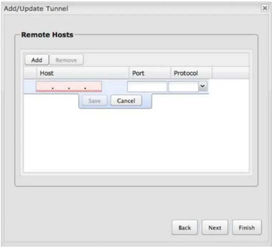
- Host – IP address of the remote server.
- Port – Specify the port if desired.
- Protocol – Select UDP or TCP.
Add/Edit Tunnel – Certificate Settings
Generate or upload certificates for OpenVPN.
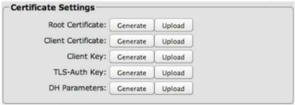
If the Configuration Mode is set to Simple, you have the option to set the TLS-Auth Key.
If the Configuration Mode is set to Advanced, set any of the following:
- Root Certificate
- Client Certificate
- Client Key
- TLS-Auth Key
- DH Parameters
VPN Tunnels
VPN (virtual private network) tunnels are used to establish a secure connection to a remote network over a public network. For example, VPN tunnels can be used across the Internet by an individual to connect to an office network while traveling, or by two office networks to function as one network. The two networks set up a secure connection across the (normally) unsecure Internet by assigning VPN encryption protocols.
CradlePoint VPN tunnels use IPsec (Internet Protocol security) to authenticate and encrypt packets exchanged across the tunnels. To set up a VPN tunnel with a CradlePoint router on one end, there must be another device (usually a router) that also supports IPsec on the other end.
IKE (Internet Key Exchange) is the security protocol in IPsec. IKE has two phases, Phase 1 and Phase 2. The router has several different security protocol options for each phase, but the default selections will be sufficient for most users.
The VPN tunnel status page allows you to view the state of the VPN tunnels. If a tunnel fails to connect to the remote site, check the System Logs for more information. You may double click on a cell to directly edit that information.
| VPN Tunnels | |||||
| Add Edit Remove Disable VPN Service | |||||
| Name | Local Networks | Remote Networks | IKE Phase 1 | IKE Phase 2 | |
| office_tunnel Enabled Tunnel Mode On Demand | 192.168.0.0 / 24 | espn.go.com 10.1.1.0 / 24 | Main AES 128, AES 256, Blow MD5, SHA1, SHA2 256, Group 1, Group 2, Group Lifetime: 28800 | PFS Enabled AES 128, AES 256, Blow MD5, SHA1, SHA2 256, Group 1 Lifetime: 3600 | |
Click Add to configure a new VPN tunnel; click Edit to make changes to an existing tunnel.
Add/Edit Tunnel – General
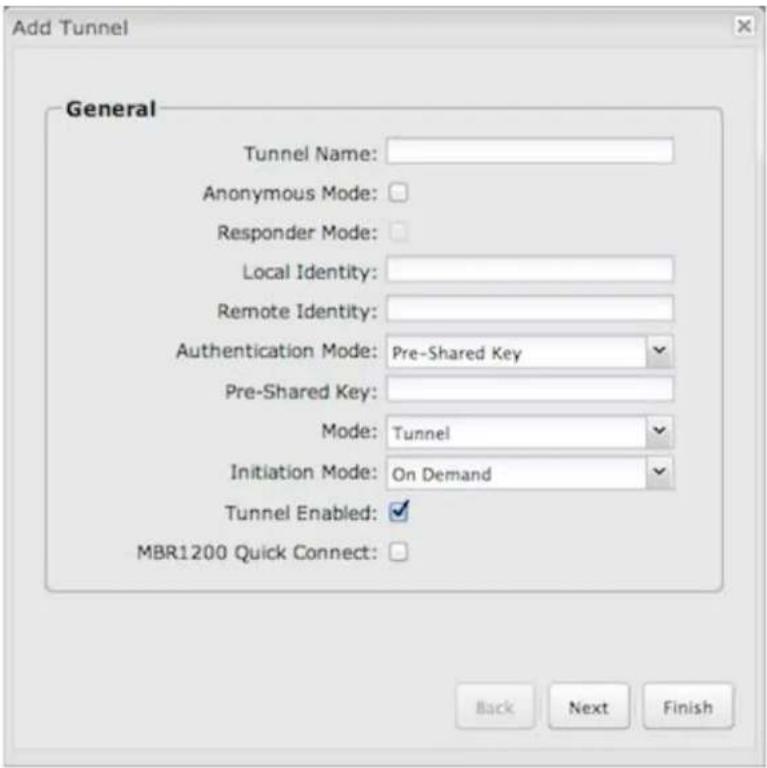
Tunnel Name: Give the tunnel a name that uniquely identifies it.
Anonymous Mode: Select to allow remote connections from any IP address.
Responder Mode: When enabled, the router will not initiate negotiation with peers, otherwise start negotiations as soon as possible.
Local Identity: Specifies the identifier sent to the remote host during phase 1 negotiation. If left blank it will default to the IP address of the WAN connection. Currently we only support identifiers in the form of an IP address, a user-fully qualified domain name (user@mydomain.com) or just a fully qualified domain name (www.mydomain.com). If the remote side of the tunnel is configured to expect an identifier, then both must match in order for the negotiation to succeed. If NAT-T is being used, a single word (instead of an address) can be used if a DynDNS connection is not being used.
Remote Identity: Specifies the identifier we expect to receive from the remote host during phase 1 negotiation. If no identifier is defined then no verification of the remote peer's identification will be done. Currently we only support identifiers in the form of an IP address, a user-fully qualified domain name (user@mydomain.com) or just a fully qualified domain name (www.mydomain.com). If left blank we will default to the IP address of the WAN connection. If NAT-T is being used, a single word (instead of an address) can be used if a DynDNS connection is not being used.
Authentication Mode: Select from Pre-Shared Key and Certificate. Pre-Shared Key is used when there is a single key common to both ends of the VPN. Certificate requires the creation of a set of certificates and a private key that can be uploaded to the router. Select Enable Certificate Support in the Global VPN Settings section to upload a single set of certificates for the router to use.
Pre-Shared Key: Create a password or key. The routers on both sides of the tunnel must use this same key.
Mode: Tunnel or Transport. Tunnel Mode is used for protecting traffic between different networks, when traffic must pass through an intermediate, untrusted network. Transport Mode is used for end-to-end communications (for example, for communications between a client and a server).
Initiation Mode: Always On or On Demand. Always On is used if you want the tunnel to initiate the tunnel connection whenever the WAN becomes available. Select On Demand if you want the tunnel to initiate a connection if and only if there is data traffic bound for the remote side of the tunnel.
Tunnel Enabled: Enabled or Disabled.
MBR1200 Quick Connect: VPN tunnels in more advanced CradlePoint devices have more choices than they did in the MBR1200, so they are more complex to configure now. Check this box to simplify setup by streamlining your options to match the old settings from the CradlePoint MBR1200.
Add/Edit Tunnel – Local Gateway
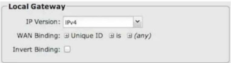
IP Version: Select IPv4 or IPv6
WAN Binding: WAN Binding is an optional parameter used to configure the VPN tunnel to ONLY operate when the specified WAN device(s) are available and connected. An example use case is when there is a router with both a primary and failover WAN device and the tunnel should only be used when the system has failed over to the backup connection.
Make a selection for "When," "Condition," and "Value" to create a WAN Binding. The condition will be in the form of these examples:
| When Condition Value | |
| Port is USB Port 1 | |
| Type is not WiMAX |
- When
- Port – Select by the physical port on the router that you are plugging the modem into (e.g., "USB Port 2").
- Manufacturer – Select by the modem manufacturer (e.g., "CradlePoint Inc.).
- Model – Set your rule according to the specific model of modem.
- Type – Select by type of Internet source (Ethernet, LTE, Modem, Wireless as WAN, WiMAX).
- Serial Number – Select a 3G or LTE modem by the serial number.
- MAC Address – Select a WIMAX modem by MAC Address.
- Unique ID – Select by ID. This is generated by the router and displayed when the device is connected to the router.
- Condition: Select "is," "is not," "starts with," "contains," or "ends with" to create your condition's statement.
- Value: If the correct values are available, select from the dropdown list. You may need to manually input the value.
Invert WAN Binding: Advanced option that inverts the meaning of WAN Binding to only establish this tunnel when the specified WAN Binding device(s) are NOT connected.
Add/Edit Tunnel – Local Networks
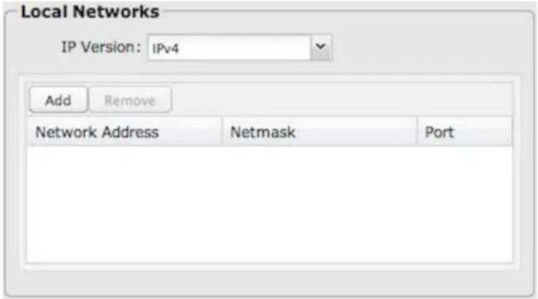
IP Version: Select IPv4 or IPv6
The Network Address and the Netmask define what local devices have access to or can be accessed from the VPN tunnel.
NOTE: the local network IP address MUST be different from the remote network IP address.
Optionally: A Port can be defined that will limit the traffic going through the VPN tunnel to only that port. If the field is left blank, any port will be accepted by the tunnel.
Add/Edit Tunnel – Remote Gateway

Gateway: This value can be any of the following: an IPv4 address, an IPv6 address, or a fully qualified name in the form of "host.domain.com" (DNS names are case-insensitive, so only lower case letters are allowed). It is recommended that you use a dynamic DNS hostname instead of the static IP address — by using the dynamic DNS hostname, updates of the remote WAN IP are compensated for while connecting to a VPN tunnel.
Add/Edit Tunnel – Remote Networks
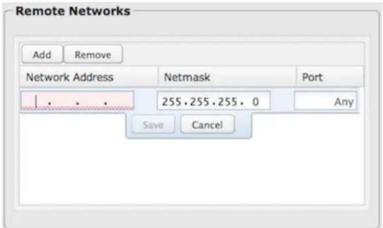
The Network Address and the Netmask define the remote network address range that local devices will have access to via the VPN tunnel.
NOTE: the remote network IP address MUST be different from the local network IP address.
Optionally: A Port can be defined that will limit the traffic going through the VPN tunnel to only that port. If the field is left blank, any port will be accepted by the tunnel.
Add/Edit Tunnel – IKE Phase 1
IKE security has two phases, Phase 1 and Phase 2. You have the ability to distinctly configure each phase, but the default settings will be sufficient for most users.
To set up a tunnel with a remote site, you need to match your tunnel's IKE negotiation parameters with the remote site. By selecting several encryption, hash, and DH group options, you improve your chances for a successful tunnel negotiation. For greatest compatibility, select all options; for greatest security, select only the most secure options that your devices support.
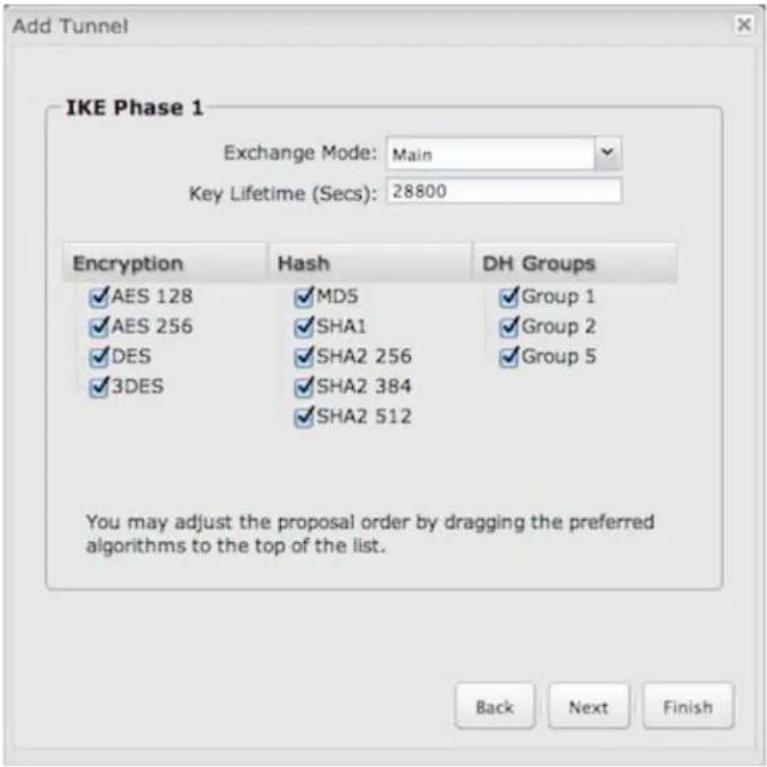
Exchange Mode: The IKE protocol has 2 modes of negotiating phase 1 – Main (also called Identity Protection) and Aggressive.
• In Main mode, IKE separates the key information from the identities, allowing for the identities of peers to be secure at the expense of extra packet exchanges.
• In Aggressive mode, IKE tries to combine as much information into fewer packets while maintaining security. Aggressive mode is slightly faster but less secure.
Because it has better security. Main mode is recommended for most users.
Key Lifetime: The lifetime of the generated keys of Phase 1 of the IPsec negotiation from IKE. After the time has expired, IKE will renegotiate a new set of Phase 1 keys.
Encryption, Hash, and DH Groups
Each IKE exchange uses one encryption algorithm, one hash function, and one DH group to make a secure exchange.
Encryption: Used to encrypt messages sent and received by IPsec.
Hash: Used to compare, authenticate, and validate that data across the VPN arrives in its intended form and to derive keys used by IPSec.
MD5
SHA1
• SHA2 256
• SHA2 384
• SHA2 512
Note that some Encryption/Hash combinations (e.g., 3DES with SHA2 384/512) are computationally expensive, impacting WAN performance. AES is as strong an encryption and performs much better than 3DES.
DH Groups: The DH (Diffie-Hellman) Group is a property of IKE and is used to determine the length of prime numbers associated with key generation. The strength of the key generated is partially determined by the strength of the DH Group. Group 5, for instance, has greater strength than Group 2.
• Group 1: 768-bit key
• Group 2: 1024-bit key
• Group 5: 1536-bit key
In IKE Phase 1 you can only select one DH group if you are using Aggressive exchange mode.
By default, all the algorithms (encryption, hash, and DH groups) supported by the device are checked, which means they are allowed for any given exchange. Deselect these options to limit which algorithms will be accepted. Be sure to check that the router (or similar device) at the other end of the tunnel has matching algorithms.
The algorithms are listed in order by priority. You can reorder this priority list by clicking and dragging algorithms up or down. Any selected algorithm may be used for IKE exchange, but the algorithms on the top of the list are more likely to be used more often.
Add/Edit Tunnel – IKE Phase 2
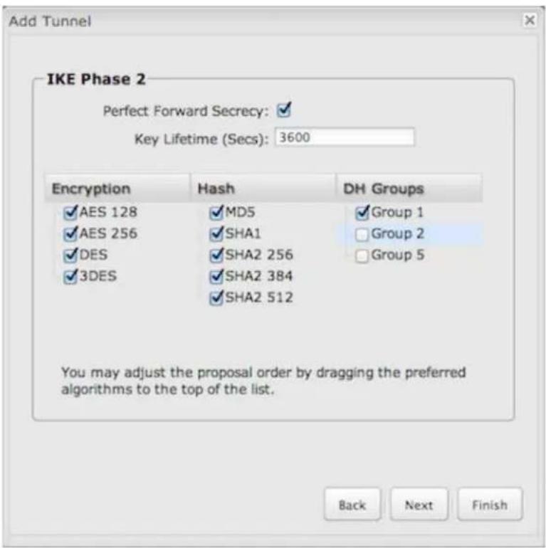
Perfect Forward Secrecy (PFS): Enabling this feature will require IKE to generate a new set of keys in Phase 2 rather than using the same key generated in Phase 1. Additionally, with this option enabled the new keys generated in Phase 2 are exchanged in an encrypted session. Enabling this feature affords the policy greater security.
Key Lifetime: The lifetime of the generated keys of Phase 2 of the IPsec negotiation from IKE. After the time has expired, IKE will renegotiate a new set of Phase 2 keys.
Phase 2 has the same selection of Encryption, Hash, and DH Groups as Phase 1, but you are restricted to only one DH Group. Phase 2 and Phase 1 selections do not have to match.
Add/Edit Tunnel – Dead Peer Detection
Dead Peer Detection (DPD) defines how the router will detect when one end of the IPsec session loses connection while a policy is in use.
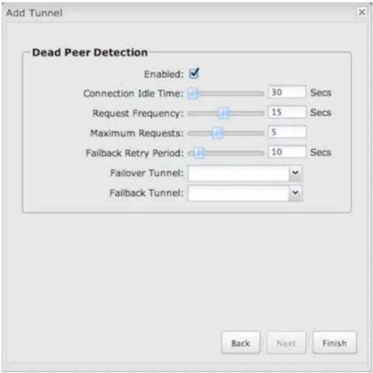
Connection Idle Time: Configure how long the router will allow an IPsec session to be idle before beginning to send Dead Peer Detection (DPD) packets to the peer machine. (Default: 30 seconds. Range: 10 - 3600 seconds.)
Request Frequency allows you to adjust the delay between these DPD packets. (Default: 15 seconds. Range: 2 – 30 seconds.)
Maximum Requests: Specify how many requests to send at the selected time interval before the tunnel is considered dead. (Default: 5. Range: 2 - 10.)
Failback Retry Period: If you have VPN tunnel failover/failback enabled (see below), set the time period between each check on the primary network after failover. (Default: 10 seconds. Range: 5 – 60 seconds.)
Failover Tunnel and Failback Tunnel: Use these settings to create two tunnels – one as the primary tunnel and one as the backup tunnel. To configure tunnel failover/failback, complete the following steps:
- Create two tunnels: one for primary and one for backup. Make sure that both tunnels have the same Remote Network and that both have Dead Peer Detection enabled.
- Choose one to be the primary tunnel. Open the editor for this tunnel and make sure Tunnel Enabled is selected. Then go to the Dead Peer Detection page. Under Failover Tunnel select the other tunnel you have created.
- Open the editor for the failover tunnel. Make sure Tunnel Enabled is not selected. On the Dead Peer Detection page, set the Failback Tunnel to your primary tunnel.
Global VPN Settings
These settings apply to all configured VPN tunnels.
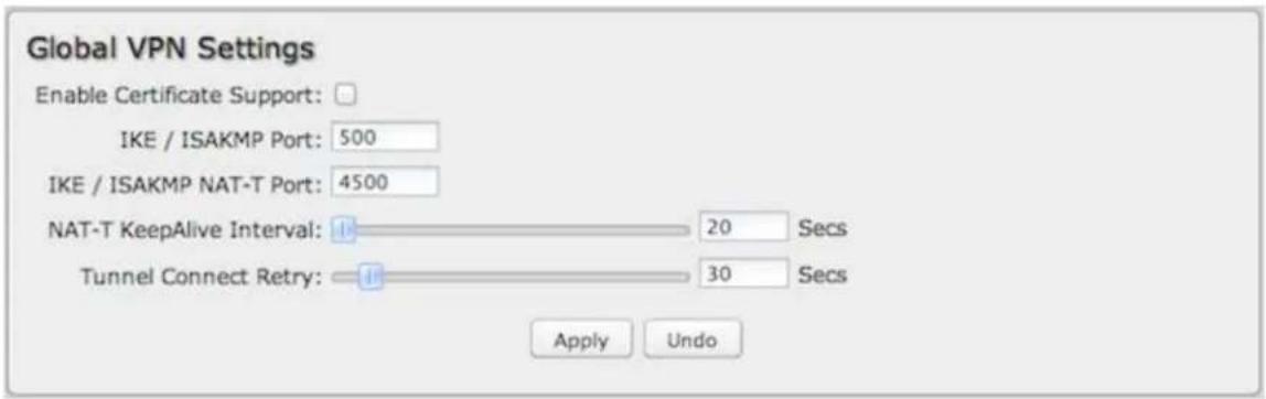
Enable Certificate Support: Enabling Certificate Support will allow you to load a certificate for VPN to the router. Click the "Upload Certificate" button to browse for a certificate on a local device. Disabling certificate support will no longer use any previously loaded certificate but will not delete it from the router. Only one certificate at a time is supported.
IKE / ISAKMP Port: Internet Key Exchange / Internet Security Association and Key Management Protocol port. (Default: 500. This is a standard VPN port that usually does not need to be changed.)
IKE / ISAKMP NAT-T Port: Internet Key Exchange / Internet Security Association and Key Management Protocol network address translation traversal port. (Default: 4500. This is a standard VPN NAT-T port that usually does not need to be changed.)
NAT-T KeepAlive Interval: Number of seconds between sending NAT-T packets to keep the tunnel alive if no other traffic is being sent. (Default: 20 seconds. Range: 0-3600 seconds. 20 seconds will be sufficient in almost all cases.)
Tunnel Connect Retry: Number of seconds between connection attempts. (Default: 30 seconds, Range: 10-255 seconds, 30 seconds will be sufficient in almost all cases.)
VPN with NAT-T
If one side of a planned VPN tunnel is behind a NAT (network address translation) firewall, the setup of your tunnel requires the following specifications:
- Each side of the tunnel must use both a Local Identity and a Remote Identity. These must match the identities on the other side: The Local Identity must match the Remote Identity on the other side of the tunnel, and vice versa. In this case, these identities can each be a simple word.
- The Tunnel Name for the side of the tunnel that is not behind the NAT firewall must be "anonymous".
- The VPN tunnel must be initiated from the side that is behind the NAT firewall.
WAN Affinity / Load Balancing
Load Balance

Select the Load Balance Algorithm from the following dropdown options:
• Round-Robin: Evenly distribute each session to the available WAN connections.
- Rate: Distribute load based on the current upload and download rates. A WAN device's upload and download bandwidth values can be set in Internet → Connection Manager.
- Spillover: This was the default algorithm in older (version 3) firmware. Load is always given to devices with the most available bandwidth. The estimated bandwidth rate is based on a combination of the upload and download configuration values and the observed capabilities of the device.
• Data Usage: This mode works in concert with the Data Usage feature (Internet → Data Usage). The router will make a best effort to keep data usage between
interfaces at a similar percentage of the assigned data cap in the data usage rule for each interface, rather than distributing sessions based solely on bandwidth. For proper functioning you need to create data usage rules for each WAN device you will be load balancing. Make certain to select the "Use with Load Balancing" checkbox in the data usage rule editor.
WAN Affinity
WAN Affinity rules allow you to manage traffic in your network so that particular bandwidth uses are associated with particular WAN sources. This allows you to prioritize bandwidth.
EXAMPLE: You could specify that your guest LAN is only associated with your Ethernet connection with no failover. Then if your Ethernet connection goes down and the embedded modem connects for failover for your primary LAN, your guest LAN will not take bandwidth from your primary LAN, saving you money.
Click Add to open the WAN Affinity Policy Editor and create a new WAN Affinity rule.
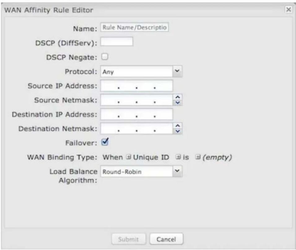
Name: Give a name for your rule that is meaningful to you.
DSCP (DiffServ): Differentiated Services Code Point is the successor to TOS (Type of Service). Use this field to select traffic based on the DSCP header in each IP packet. This field is sometimes set by latency sensitive equipment such as VoIP phones. If you know specific DSCP values, you can input one here.
DSCP Negate: When checked this rule will match on any packet that does NOT match the DSCP field.
Protocol: Select from the dropdown list to specify the protocol for a particular data use. Otherwise, leave "Any" selected.
Source IP Address, Source Netmask, Destination IP Address, and Destination Netmask: Specify an IP address or range of IP addresses by combining an IP address with a netmask for either "source" or "destination" (or both). Source vs. destination is defined by traffic flow. Leave these blank to include all IP addresses (such as if
your rule is defined by a particular port instead).
EXAMPLE: If you want to associate this rule with your guest LAN, you could input the IP address and netmask for the guest LAN here (leaving the last slot "0" to allow for any user attached to the guest network):
• Source IP Address: 192.168.10.0
• Source Netmask: 255.255.255.0
Failover: (Default: Selected.) When this is selected and traffic from the chosen WAN device for this rule is interrupted, the router will fail over to another available WAN device. Deselect this option to restrict this traffic to only the selected WAN interface.
WAN Binding Type: You have several options for specifying the type of WAN interface(s) you want associated with your rule. Make a selection for "When," "Condition," and "Value" to assign a WAN Binding Type. The condition will be in the form of these examples:
| When Condition Value | |
| Port is USB Port 1 | |
| Type is not WiMAX |
- When:
- Port – Select by the physical port on the router that you are plugging the modem into (e.g., "USB Port 2").
- Manufacturer – Select by the modem manufacturer (e.g., "CradlePoint Inc.).
- Model – Set your rule according to the specific model of modem.
- Type – Select by type of Internet source (Ethernet, LTE, Modem, Wireless as WAN, WiMAX).
- Serial Number – Select a 3G or LTE modem by the serial number.
- MAC Address – Select from a dropdown list of attached devices.
- Unique ID – Select by ID. This is generated by the router and displayed when the device is connected to the router.
- Condition: Select "is," "is not," "starts with," "contains," or "ends with" to create your condition's statement.
- Value: If the correct values are available, select from the dropdown list. You may need to manually input the value.
Load Balance Algorithm: Select the Load Balance Algorithm for this WAN Affinity rule from the following dropdown options:
• Round-Robin: Evenly distribute each session to the available WAN connections.
- Rate: Distribute load based on the current upload and download rates. A WAN device's upload and download bandwidth values can be set in Internet → Connection Manager.
- Spillover: This was the default algorithm in older (version 3) firmware. Load is always given to devices with the most available bandwidth. The estimated bandwidth rate is based on a combination of the upload and download configuration values and the observed capabilities of the device.
- Data Usage: This mode works in concert with the Data Usage feature (Internet → Data Usage). The router will make a best effort to keep data usage between interfaces at a similar percentage of the assigned data cap in the data usage rule for each interface, rather than distributing sessions based solely on bandwidth. For proper functioning you need to create data usage rules for each WAN device you will be load balancing. Make certain to select the "Use with Load Balancing" checkbox in the data usage rule editor.
WiFi as WAN
WiFi as WAN uses an outside WiFi network as its Internet source. When WiFi as WAN is enabled, the router will find other WiFi networks that you can select and connect to. Unless a selected WiFi source is on an unprotected network, you will need to know its password or key.
To enable WiFi as WAN, first select the desired WiFi radio:
• WiFi Radio #1 (2.4 GHz)
- WiFi Radio #2 (5 GHz)
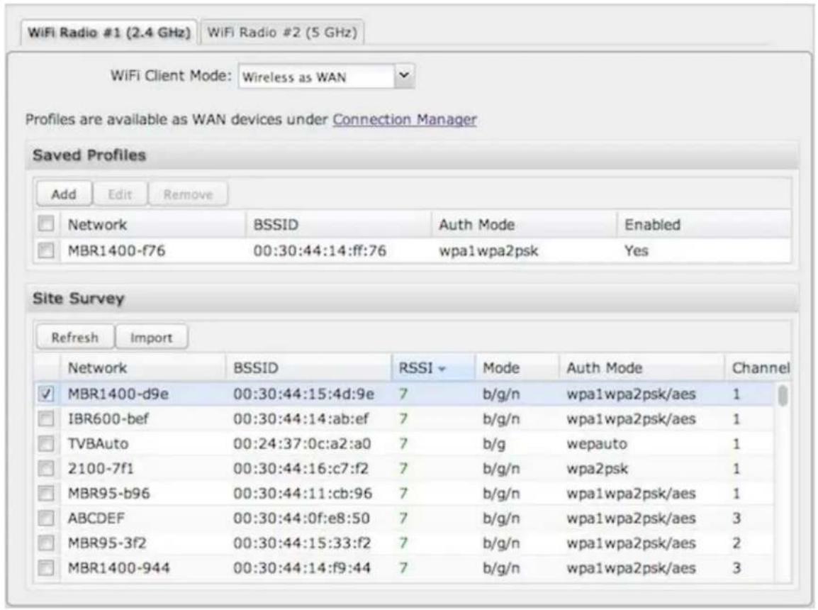
All CradlePoint routers and some other routers use the same default IP address for the primary network: 192.168.0.1. If you attempt to set up WiFi as WAN and there is an "IP conflict," you need to change the IP address. The router is attempting to use the same IP address for both WAN and LAN, which is impossible. Go to Network Settings → WiFi / Local Networks. Select the network and click Edit. You can change the IP address under IPv4 Settings. For example, you might change 192.168.0.1 to 192.168.1.1.
Saved Profiles
This is a list of WiFi networks that have already been configured as WAN sources. The router will attempt to connect to any of these access points using the password you have configured. If more than one access point is in range, then the router will connect with the highest priority network.
Network: The name (SSID, or Service Set Identifier) that is broadcast by the access point.
BSSID: The numeric ID of the network (Basic Service Set Identifier). This parameter is required when trying to connect to a hidden network using WiFi as WAN. It is optional when connecting to a visible network. If it is set in a profile, both the SSID and BSSID must match to connect to an access point. If the BSSID is not set in a profile, then the router will connect to any access point that matches the given SSID.
Auth Mode: The type of encryption that is used by the network.
- None
• WEP Auto - WEP Open
- WEP Shared
• WPA1 Personal - WPA2 Personal
• WPA1 & WPA2 Personal
You have two options for adding network profiles:
• Automatic – Select a WiFi network in Site Survey and click Import
- Manual – Click on Add under Saved Profiles and input the required information.
Site Survey
This is a list of WiFi networks that the router can currently find, along with information about the network such as its mode and channel. Click "Refresh" if a WiFi network you want to connect to is invisible. You can sort the list based on any of the fields by clicking on the field name.
If you import a network from Site Survey, most of the information about the network will already be completed. You need to input the password (if there is one) and then click submit to save the WiFi as WAN profile:
Wireless Scan Settings
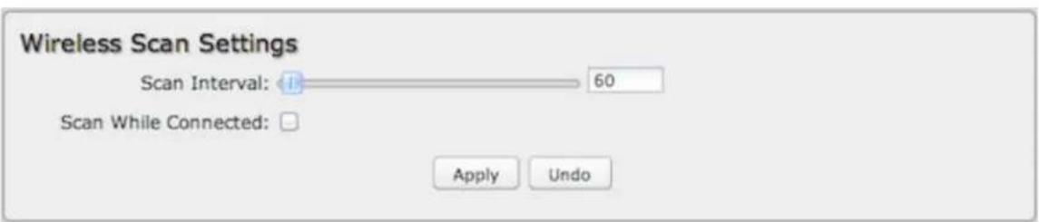
Scan Interval: How often WiFi as WAN scans the environment for updates. (Default: 60 seconds, Range: 5–3600 seconds.)
Scan While Connected: Continue to scan for WiFi as WAN profile updates when connected. Each time a scan occurs the wireless communication of the router will be temporarily interrupted. Normally this should be disabled.
System Settings
The System Settings section of the Administration Pages provides access to tools for broad administrative control of the router. The System Settings tab has the following dropdown menu items:
- Administration
• Certificate Management
• Device Alerts - GPIO Connector
• Enterprise Cloud Manager
• Feature Licenses - Hotspot Services
- Serial Redirector
• SNMP Configuration - System Control
- System Software
Administration
Select the Administration submenu item in order to control any of the following functions:
- Router Security
- System Clock
- Local Management
- Remote Management
GPS
• SMS -
System Logging
-
Router Services
- Temperature
Router Security
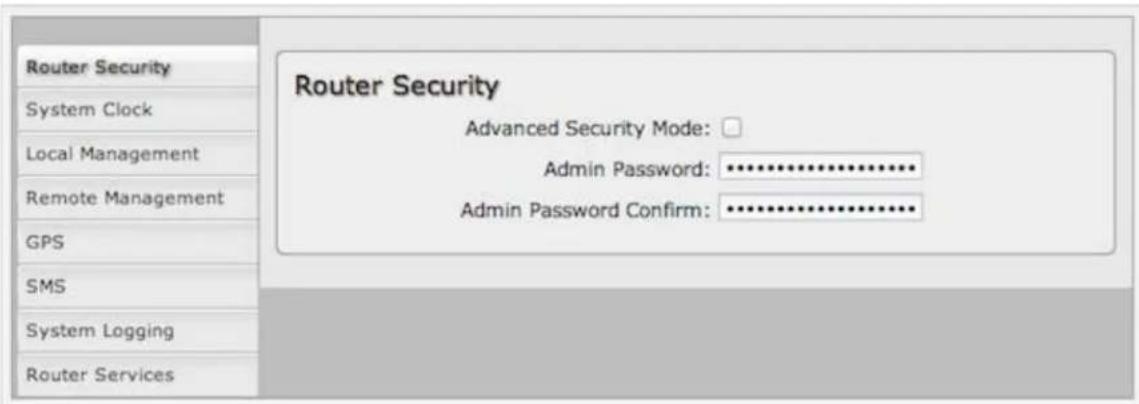
Advanced Security Mode – Select to enable the following additional security features and options:
• TACACS+ and RADIUS server authentication options
• Option for multiple users
- Increase password security:
- minimum 7 characters
- at least 1 alpha and 1 numeric character
- 30-minute lockout after 6 failed login attempts
Admin Password – Enter a password for the administrator who will have full access to the router's management interface. You can use the default password on the back of your product, or you can create a custom Administrator Password.
Advanced Security Mode
When you enable Advanced Security Mode, you have three different options for the Authentication Mode:
- Local Users
• TACACS+
• RADIUS
Local Users
Create users with administrative privileges by inputting usernames and passwords in the Advanced User Management table. The default username is "admin," but you can edit this name, or delete it once you create other users (you can't delete the user you are currently signed in as).
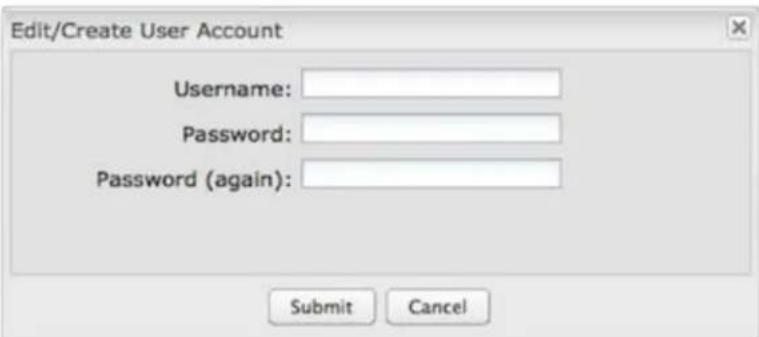
In TACACS+ and RADIUS modes, if the servers cannot be reached, either because the WAN is down or a response is not received within the selected Server Timeout, the router will automatically fall back to using Local Users mode to prevent any potential of being locked out.
TACACS+
TACACS+ stands for "Terminal Access Controller Access-Control System plus". The router will use a TACACS+ server (or two, optionally) to authorize administration.
-
Server Timeout – If the servers are not reached within the set time (possibly because the WAN is down), the router will automatically fall back to using Local Users mode to prevent users from being locked out.
• Authentication Service – Choose from: -
ASCII / Login
- PAP
-
CHAP
-
Server Address – This can be either an IP address in the form of "1.2.3.4", or a DNS name in form of "host.domain.com". Only lower case letters are allowed for a DNS name.
- Port - Port 49 is default for TACACS+.
- Shared Secret
RADIUS
RADIUS stands for "Remote Authentication Dial In User Service". The router will use a RADIUS server (or two, optionally) to authorize administration.
- Server Timeout – If the servers are not reached within the set time (possibly because the WAN is down), the router will automatically fall back to using Local Users mode to prevent users from being locked out.
- Server Address – This can be either an IP address in the form of "1.2.3.4", or a DNS name in form of "host.domain.com". Only lower case letters are allowed for a DNS name.
• Port – Port 1812 is common for RADIUS servers. - Shared Secret
System Clock
Enabling NTP will tell the router to get its system time from a remote server on the Internet. If you do not enable NTP then the router time will be based on when the router firmware was built, which is guaranteed to be wrong. Whenever the Internet connection is re-established and once a week thereafter the router will ask the server for the current time so it can correct itself.
You then have the option of selecting an NTP server and adjusting the NTP server port. Select the NTP server from the dropdown list, Any of the given NTP servers will be sufficient unless, for example, you need to synchronize your router's time with other devices in a network.
• Time Zone – Select from a dropdown list. Setting your Time Zone is required to properly show time in your router log.
- Daylight Savings Time — Select this checkbox if your location observes daylight savings time.
Local Management
Local Management
- Enable Internet Bounce Pages – Bounce pages show up in your web browser when the router is not connected to the Internet. They inform you that you are not connected and try to explain why. If you disable bounce pages then you will just get the usual browser timeout, in the normal case when the router is connected to the Internet you don't see them at all.
- Disable Attention LED – This disables the Attention LED. This will take effect at the next reboot.
- Local Domain – The local domain is used as the suffix for DNS entries of local hosts. This is tied to the hostnames of DHCP clients as DHCP_HOSTNAME.LOCAL_DOMAIN.
- System Identifier – This is a customizable identity that will be used in router reporting and alerting. The default value is the product name and the last three characters of the MAC address of the router.
- Require HTTPS Connection – Check this box if you want to encrypt all router administration communication.
- Secure HTTPS Port – Enter the port number you want to use. The default is 443
- Enable SSH Server – When the router's SSH server is enabled you may access the router's command line interface (CLI) using the standards-based SSH protocol. Use the username "admin" and the standard system password to log in.
• SSH Server Port – Default: 22.
Remote Management
Remote Management allows a user to enable incoming WAN pings or charge settings for the router from the Internet using the router's Internet address.
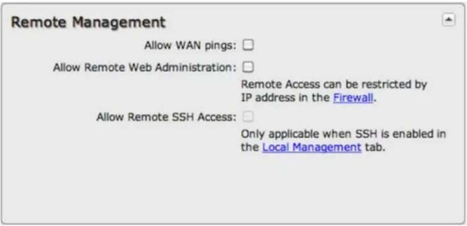
Allow WAN pings – When enabled the functionality allows an external WAN client to ping the router.
Allow Remote Web Administration – When remote administration is enabled it allows access to these administration web pages from the Internet. With it disabled, you must be a client on the local network to access the administration website. For security, remote access is usually done via a non-standard http port. Additionally, encrypted connections can be required for an added level of security.
- Require HTTPS Connection – Requiring a secure (https) connection is recommended.
- HTTP Port: Default – 8080. This option is disabled if you select "Require Secure Connection".
Secure HTTPS Port – Default: 8443.
NOTE: You can restrict remote access to only specified IP addresses in Network Settings → Firewall under Remote Administration Access Control.
Allow Remote SSH Access – This will enable SSH access to the router from the Internet. It is only available when SSH access is enabled in the Local Management tab. Some carriers block the remote SSH access ports. If a ping to the router's WAN port does not work, it is unlikely that remote SSH access will work.
GPS
If you have an attached device with GPS support (SIM-based models with GPS support require that the SIM is inserted), you can enable a graphical view of your router's location, which appears in Status → GPS. You can also enable GPS NMEA format sentence reporting (or TAIP for the COR IBR1100/IBR1150) to a server (LAN, WAN, or remote). This GPS reporting functionality requires a separate software client to listen/query for these sentences.
NOTE: Some carriers disable GPS support in otherwise supported modems. If you encounter issues with obtaining a fix, contact your carrier and ensure that GPS is supported.
GPS
Enable GPS support: √
Keep GPS Active: □
Include System ID : □
Prepend System ID : □
Report NMEA GGA sentences: √
Report NMEA RMC sentences: □
Report NMEA VTG sentences: □
Report Interval: 10
Enable GPS server on WAN: □
Enable GPS server on LAN: □
Enable GPS reporting to remote server: □
NOTE: Some of the following options are specific to CradlePoint COR products.
- Enable GPS support – Enables support for querying GPS information from supported modems.
- Keep GPS Active – Keep the GPS receiver active at all times, even if no destination exists for position messages. This will place additional load on the router similar to sending reports to a remote server, but without consuming the network bandwidth.
- Include System ID – Include the router's "System ID" sentence with every data message. This can be useful when a single remote client or server is handling NMEA position reports from multiple routers. This creates a custom GPS sentence with the System ID as part of the sentence and the checksum.
- Prepend System ID – Include the router's "System ID" sentence with every GPS message. This can be useful when a single remote client or server is handling GPS position reports from multiple routers. This simply prepends the system id and a comma ahead of the GPS sentence.
- Report NMEA GGA sentences – Report GPS fix using NMEA GGA sentence format (if available).
- Report NMEA RMC sentences – Report GPS fix using NMEA RMC sentence format (if available).
• Report NMEA VTG sentences – Report GPS fix using NMEA VTG sentence format (if available). - Report Interval – Set the interval in seconds between periodic NMEA sentence reports. Use as long an interval as is practical for your application. The shorter the interval the more router resources and bandwidth will be used by the GPS subsystem. Too frequent reports may cause performance and/or availability issues.
- Enable GPS server on WAN – Enables a TCP server on the WAN side of the firewall, which will periodically send GPS NMEA sentences to connected clients.
- Enable GPS server on LAN – Enables a TCP server on the LAN side of the firewall, which will periodically send GPS NMEA sentences to connected clients.
- GPS server port number
- Enable GPS reporting to remote server – Enables periodic reporting of GPS NMEA sentences to a remote server. The router will buffer NMEA data if errors are encountered or if the Internet connection goes down and send the buffered sentences when the connection is restored.
-
Remote server hostname or IP
-
Remote server port
- Report only over specific time interval – Restricts the NMEA sentence reporting to a remote server to a specific time interval.
Depending on your selections (and other possible factors), reporting may include proprietary sentences. For example, if you select Include System ID, the report will include proprietary sentences of the following format (in addition to the standard sentences):
$PCPTI, {System ID}, {router timestamp}, {GGA timestamp}, {GGA checksum} * {checksum}
"PCPTI" stands for Proprietary, CradlePoint, Identification (P-CPT-).
NMEA GGA, RMC, and VTG sentences
The device reports GPS information with multiple NMEA (National Marine Electronics Association) sentence formats: GGA, RMC, and VTG. For more examples and information about NMEA sentences, see the following websites:
http://aprs.gids.nl/nmea/
http://www.gpsinformation.org/dale/nmea.htm#nmea
GGA
\$GPGGA – Essential fix data including 3D location and accuracy information
Example: \$GPGGA,1753405,4916.450,N,12311.127,W,2,06,1.5,117.3,M,-26.574,M,6.0,0138*47
| Sample Data Description | |
| 1753405 Time of fix – 17:34:05 UTC | |
| 4916.450,N Latitude 49 deg. 16.450 min North | |
| 12311.127,W Longitude 123 deg. 11.127 min West | |
| 2 | Fix quality: 0 = fix not available; 1 = GPS fix; 2 = Differential GPS fix; 3 = PPS fix; 4 = Real Time Kinematic; 5 = Float RTK; 6 = estimated (dead reckoning); 7 = Manual input mode; 8 = Simulation mode |
| 06 Number of satellites being tracked | |
| 1.5 Horizontal dilution of precision (HDOP) – relative accuracy of horizontal position | |
| 117.312,M Altitude in meters above mean sea level | |
| -26.574,M | Geoidal separation: height of mean sea level above WGS-84 earth ellipsoid (negative value means mean sea level is below ellipsoid) |
| 6.0 Time in seconds since last update from differential reference stations | |
| 0138 Differential reference station ID number | |
| *47 Checksum – used by program to check for transmission errors | |
RMC
\$GPRMC – Recommended minimum specific GPS/transit data
Example: \$GPRMC,225446,A,4916.45,N,12311.12,W,000.5,054.7,191194,020.3,E*68
| Sample Data Description | |
| 225446 Time of fix – 22:54:46 UTC | |
| A Navigation receiver warning A = OK, V = warning | |
| 4916.45,N | Latitude 49 deg. 16.45 min North |
| 12311.12,W | Longitude 123 deg, 11.12 min West |
| 000.5 | Speed over ground, knots |
| 054.7 Course made good, true |
| 191194 Date of fix - 19 November 1994 |
| 020.3,E Magnetic variation: 20.3 degrees East |
| *68 Checksum is mandatory for RMC |
VTG
GPVTG – Vector track and speed over ground Example: GPVTG,054.7,T,034.4,M,005.5,N,010.2,K
| Sample Data Description |
| 054.7,T Track, degrees relative to true north |
| 034.4,M Track, degrees relative to magnetic north |
| 005.5,N Ground speed, knots |
| 010.2,K Ground speed, kilometers per hour |
TAIP - COR IBR1100/IBR1150 only
The COR IBR1100/IBR1150 gives you the option to select the GPS language: NMEA or TAIP.
The Trimble ASCII Interface Protocol (TAIP) was designed for vehicle tracking. Selecting TAIP reveals additional options specific to the protocol.
![GPS Enable GPS support: ✓ Keep GPS Active: □ Select the GPS language: TAIP ✓ Enable Vehicle ID: □ Vehicle ID #: 0000 Enable TAIP message checksum reporting: ✓ Enable the appending of [CR][LF] □ characters to each TAIP message: Report TAIP AL sentences: □ Report TAIP CP sentences: □ Report TAIP ID sentences: □ Report TAIP LN sentences: □ Report TAIP PV sentences: □ Report Interval: 10 Enable GPS server on WAN: □ Enable GPS server on LAN: □ Enable GPS reporting to remote server: □](/content/2026/06/1204652/images/9de5909fe569601a7f9b357e483ef015df5472de93211d2d64fe268bcc4b23c5.jpg)
- Enable Vehicle ID – Include a 4 character vehicle identifier
- Vehicle ID # - Assign a 4 character ID if Enable Vehicle ID is selected (default ID is 0000)
- Enable TAIP message checksum reporting – Include a 2 digit checksum
- Enable the appending of [CR][LF] characters to each TAIP message – Add a carriage return and line feed to the end of each message output
TAIP allows for several different types of messages. For typical uses, select one of the following types:
• Report TAIP AL sentences – Altitude/Up Velocity
• Report TAIP CP sentences – Compact Position Solution
• Report TAIP ID sentences – Identification Number
• Report TAIP LN sentences – Long Navigation Message
• Report TAIP PV sentences – Position/Velocity Solution
For more information about TAIP, see these instructions from Trimble.
SMS
SMS (Short Message Service, or text messaging) requires a cellular modem with an active data plan. SMS is not designed to be a full remote management feature: SMS allows you to connect to the router for a few simple queries or commands with a text messaging service (e.g., from your phone). A modem that does not have an active data connection may still be reachable by SMS because Internet traffic and SMS traffic operate on separate channels, so SMS can be used to bring on offline router back online.
SMS is enabled on the router by default. However, it only works if SMS is supported and enabled on the modem. Most modems have SMS enabled by default, but the carrier may charge a fee for each text message sent or received. Contact your carrier to review these fees and/or to enable an SMS plan.
Important notes about SMS:
- Messages are limited to 160 characters.
- SMS is not a guaranteed delivery protocol. The carriers do not guarantee that the SMS message will be delivered to the modem or that the modem's response will be delivered to the sender. This means an administrator might have to send messages multiple times before the desired action is performed.
- SMS is a slow protocol. It can take seconds or up to a few minutes for messages to be delivered.
- SMS messages are not encrypted; they are sent in full readable text over the network.
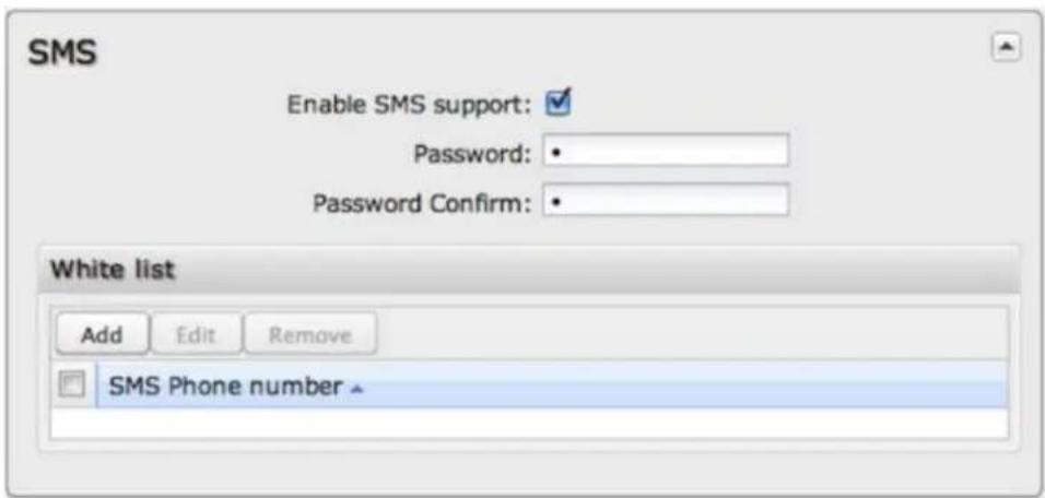
Enable SMS support – SMS support is enabled by default on the router. Deselect this to disable.
Password - By default, the password is the last 8 characters of the router's MAC address (i.e., the Default Password on the product label). You can change this password to anything between 1 and 16 characters. It should be long enough to be useful for security but short enough to easily type into your phone (or other texting client).
White List – This list is blank by default, which means that the router will accept SMS messages from any phone number. Leaving this blank is unsecure, so CradlePoint recommends that you add phone numbers to this list. Once any numbers are listed, only those numbers have the ability to connect to the router via SMS.
NOTE: You cannot add email addresses to the White list. When a phone number is added to the White List, email SMS messages will be rejected.
How to Send an SMS Message
You can send SMS messages to the router via phone or email. The key elements are:
-
the modem's MDN
-
the SMS password (defined above)
- the command
You must know the MDN (Mobile Directory Number) of the modem to send SMS messages to the router. This is a phone number that can be found under Status → Internet Connections in the router administration pages or under Devices → Network Interfaces in Enterprise Cloud Manager.
How to Text from a Phone
- Open the text messaging tool on your phone and start a new message.
- In the To field, enter the modem's MDN.
- In the Subject field, enter the SMS password and command.
- Click Send.
How to Text from an Email Account
NOTE: There are limitations with sending texts via email. The SMS engine is currently only compatible with GSM-based carrier operators.
- Start a new email message.
- In the To field, enter the modem's MDN plus the modem's carrier domain name (e.g., 2085555555@txt.att.net).
- Enter the password and command in either the Subject field or Body of the email message. If you use the subject field, leave the body blank, and if you use the body, leave the subject blank.
NOTE: The subject field may be limited to a certain number of characters, so if you get an error when sending the command on the subject line, switch to using the body instead.)
SMS Commands
Below is a list of supported SMS messages and the syntax format.
Due to security concerns, the set of commands are intentionally limited to those that can configure a modem's connection, but cannot lock the administrator out due to malicious modem changes. Therefore, if an unsolicited request adjusts the modem's configuration via SMS, an administrator can still access the modem via SMS.
Command syntax:
<password>, <command>, [arg1,][arg2,]
All commands start with the password – either the default of the last 8 digits of the router's MAC address or the administrator-configured password. Commands can have an optional number of arguments.
NOTE: The trailing comma on the command is important to allow the SMS engine to distinguish the final argument from other information the SMS client might append to the message without your knowledge.
Supported Commands
reboot – Reboot the router (not the modem)
Syntax:
<password>, reboot,
Example:
1234, reboot,
restore – Restore the router to factory defaults
Syntax:
<password>, restore,
Example:
1234, restore,
rstatus - Get router status
Syntax:
<password>, rstatus,
Example:
1234,rstatus,
mstatus – Get modem status (port parameter optional)
Syntax:
<password>,mstatus,[port,]
Examples:
1234,mstatus, //return status of highest priority modem
1234,mstatus,usb1, //return status of modem plugged into port usb1
This command returns info about the indicated modem's status. The resulting data reflects the modem model number, service type, and connection status and values.
Sample response:
Model: MC200P
Service: HSPA+
SIM Status: READY
RSSI: -62 dbm
ECIO: -4
APN: wwan.ccs
IP Addr: 166.136.142.172
mreboot – Reboot the modem (port parameter optional)
Syntax:
<password>, mreboot, [port,]
Examples
1234,mreboot, //reboot the highest priority modem
1234,mreboot,usb1, //reboot the modem plugged into port usb1
apn – Reboot the modem (port parameter optional)
Syntax:
<password>,apn,<new APN>,[port,]
Examples
1234,apn,myapn@apn.com, //set APN of highest priority modem
1234,apn,myapn@apn.com,usb1, //set APN for modem in port usb1
userpass – Set the modem's authentication username and password (port parameter optional)
Syntax:
<password>,userpass,<username>,<userpassword>,[port,]
Examples:
1234,userpass,joe,mypassword, //set information of highest priority modem
1234,userpass,joe,mypassword,usb3, //set information on modem in port usb3
simpin - Set the SIM's PIN (port parameter optional)
Syntax:
<password>, simpin, <pin>, [port,]
Examples
1234,simpin,5678, //set simpin in highest priority modem
1234,simpin,5678,usb2 //set simpin in modem on port usb2
log - Return a portion of the router log
Syntax:
<password>, log, [start,]
Examples
1234, log, //return the first 10 items of the log (items 0 through 9)
| 1234,log,10, | //return items 10 through 19 of the log |
| 1234,log,20, | //return items 20 through 29 of the log |
Sending log information via SMS messages likely results in several resulting texts. Please be aware of the costs of text messages on the modem's account, and use this command only if necessary.
* The "port" parameter is optional. It specifies which port — and therefore which modem — to perform the action on. If not given, the action will happen on the highest priority modem.
Sample Debug Session
The following is an example of a debug session to discover a modem's APN is misconfigured and needs to be set.
Figure out the state of the modems on the router:
1234, rstatus,
Receive the modem's status and settings:
1234, mstatus,
Set the modem's APN to the correct setting:
1234, apn, broadband,
Verify the APN was set properly:
1234,mstatus,
Continue to verify the status periodically to ensure that the modem connects:
1234, rstatus,
System Logging
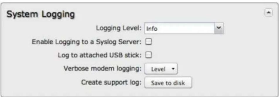
Logging Level: Setting the log level controls which messages are stored or filtered out. A log level of Debug will record the most information while a log level of Critical will only record the most urgent messages. Each level includes all messages from all of the levels below it on the list (e.g. "Warning" includes all "Error" and "Critical" messages as well).
- Debug
- Info
- Warning
- Error
• Critical
Enable Logging to a Syslog Server: Enabling this option will send log messages to a specified Syslog server. After enabling, type the Hostname or IP address of the Syslog server (or select from the dropdown menu).
- Syslog Server Address: Select the Hostname or IP address from the dropdown menu, or type this in manually.
- Include System ID: This option will include the router's "System ID" at the beginning of every log message. This is often useful when a single remote Syslog server is handling logs for several routers.
- Include UTF8 Byte Order Mark: The log message is sent using UTF-8 encoding. By default the router will attach the Unicode Byte Order Mark (BOM) to the Syslog message in compliance with the Syslog protocol, RFC5424. Some Syslog servers may not fully support RFC5424 and will treat the BOM as ASCII text, which will appear as garbled characters in the log. If this occurs, disable this option.
Log to attached USB stick: Only enable this option if instructed by a CradlePoint support agent. This will write a very verbose log file to the root level of an attached USB stick. Please disable the feature before removing the USB stick, or you may lose some logging data.
Verbose modem logging: Only enable this option if instructed by a CradlePoint support agent.
Create support log: This functionality allows for a quick collection of system logging. Create this log file when instructed by a CradlePoint support agent.
Router Services
By default, router services (Enterprise Cloud Manager, NTP, etc.) connect to the router via the WAN. In some setups it makes sense to use the LAN instead. For example, if your router is used strictly for 3G/4G failover behind another router, you may not want to use 3G/4G data unnecessarily. Select Use LAN Gateway to set your router services to connect via the LAN.
LAN Gateway Address: Input the IP address of the LAN side connection. If this is a 3G/4G failover router operating behind another router, the LAN Gateway Address is the IP address of that other router.
DNS Server and Secondary DNS Server: The primary and secondary DNS server numbers match the static DNS values (set at Network Settings → DNS). You can leave the default values or set them manually here. (Changing these values also changes the static DNS values.)
Temperature (COR IBR1100/1150 only)
The COR IBR1100/IBR1150 includes an internal temperature sensor. Use this to track the internal temperature with alerts/logging. The router also has a mechanism to shut down functions when the internal temperature is dangerously high (80 °C).
Temperature
Minimum Temperature: 10
Maximum Temperature: 70
Router Temperature (°C), Modem Temperature (°C): These display the router or modem's current temperature in degrees Celsius. To convert these values to Fahrenheit, multiply by 9, divide by 5, and then add 32 (F = 95 C + 32). You can also use an online conversion tool.
The table below gives a few reference points.
°C °F Description
100 212 Boiling point of water
37 98.6 Body temperature
21 70 Approximate room temperature
0 32 Freezing point of water
Minimum Temperature: (Default: 10 °C.) If the device drops to this temperature, an alert will automatically be generated. Maximum Temperature: (Default: 70 °C.) If the device reaches this temperature, an alert will automatically be generated.
To configure minimum and maximum temperature alerts, use one of the following methods:
- Enable these alerts in Enterprise Cloud Manager.
- Set up an SMTP email server in System Settings → Device Alerts.
Certificate Management
Through the CradlePoint administration pages you now have the ability to create, manage, sign, and import/export X.509 certificates – frequently referred to as SSL certificates – under Network Settings → Certificate Management. Our implementation integrates an OpenSSL toolkit solution. It includes the ability to create your own CA certificates and self-signed certificates.
For background information on digital certificates, see the following Wikipedia articles:
• Public key certificate
• Public key infrastructure
X.509 (ITU-T standard)
PKCS #12
Digital certificates have multiple possible uses in a CradlePoint networking setup. For example, a digital certificate is a much more secure option for VPN tunnel authentication than a pre-shared key.
Go to the following sections for more information about specific certificate management options:
- Create Certificates – includes CA certificates and self-signed certificates
• Certificate Signing Request (CSR) – generate a CSR for third-party signing - Local Certificates – list of certificates on the device; includes Remove certificate option
• Import/Export PEM Format Certificates
• Import/Export PKCS #12 Format Certificates
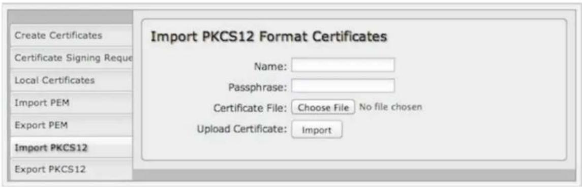
Not all Certificate Management options displayed here are currently available via the Enterprise Cloud Manager configuration pages.
Create Certificates
Complete the following fields to create certificates locally, including CA (certificate authority) certificates.
To create local certificates without sending signature requests to a third-party CA, first create a CA certificate with this interface and then create additional certificates that you sign with your CA:
- Step 1: Create a CA certificate. In the Issuer section select Set as CA certificate.
- Step 2: Create additional certificates. In the Issuer section select Sign with CA certificate and then select the CA certificate you created in step 1 from the dropdown list.
Create Certificates
General Description
Name:
Issuer
Set as CA certificate: □
Sign with CA certificate: □
Certificate Name: None
Subject
Country Name:
State or Province Name:
Local Name:
Organization Name:
Organization Unit:
Common Name:
Email Address:
Validity
Days:
Public Key Algorithm
Type:
Digest:
Bits:
Apply
Undo
General Description
• Name: Choose a name meaningful to you.
Issuer
- Set as CA certificate: Select if the certificate you are creating is intended to be a CA.
• Sign with CA certificate: Select to sign this certificate with a CA you created previously.
• Certificate Name: Select your CA certificate from the dropdown list of local certificates.
Subject
• Country Name: 2-letter country code (e.g., AU, UK, US)
• State or Province Name: The name of your state or region
Local Name: Generally the city or town
• Organization Name: Company name
• Organization Unit: Company division name
- Common Name: Must be unique; if used for authentication, this must match the configured Common Name (CN) on the third-party authenticator
- Email Address
Validity
• Days: Input the number of days the certificate should remain valid (999 days maximum)
Public Key Algorithm
• Type: Select one of the following:
- RSA
。 DSA
- Digest: The following cryptographic hash functions are listed in order of increasing security. More security requires more router resources.
。 MD5
SHA-128
SHA-256
- Bits: A greater bit size is more secure, but requires more router resources. Some devices do not support 2048 bits, so ensure compatibility.
1024
2048
Certificate Signing Request
Request a certificate signature from a remote CA. Using an established, third-party CA increases the likelihood that your certificate will be trusted by others (see security issues for self-signed certificates for more information).
Generate a certificate signing request (CSR) by selecting a certificate from the dropdown list (Name field) and downloading the CSR. The CSR can then be sent to a remote CA for a signature. Once the certificate has been signed, import the certificate in PEM or PKCS #12 format.
Certificate Signing Request
Name:
Digest:
Download CSR: Submit
When you export the CSR, select a Digest, or cryptographic hash function. These are listed in order of increasing security. More security requires more router resources.
MD5
SHA-128
SHA-256
Local Certificates
This is a table of local certificates, including certificate details.
Remove a local certificate by selecting the certificate and clicking the Remove button.
• Name: Friendly description of the certificate.
• Country: (C) The certificale owner's country of residence.
• State or Province: (ST) the certificate owner's state or province of residence
- Location: (L) The certificate issuer's locality (city, town, etc.).
• Org.: (O) The organization to which the certificate issuer belongs.
• Org. Unit: (OU) The name of the organizational unit to which the certificate issuer belongs
• Common Name: (CN) Name used to match authentication credentials.
Import/Export PEM Format Certificates
PEM is a container format for encoding data – in this case, X.509 certificates. PEM was originally designed for encoding email (PEM stands for Privacy enhanced Electronic Mail), but it has never been widely used for that purpose. The format is much more common for encoding digital certificates.
The PEM format uses Base64 and DER (Distinguished Encoding Rules) encoding
Import
Choose a certificate file in PEM format from your computer or local device and upload it to the router. Give the certificate a name that is meaningful to you.
Export
Select a local certificate from the dropdown list and download it to your computer or local device in PEM format.
Export PEM Format CA Certificates
Name:
Download Certificate:
Export
Import/Export PKCS #12 Format Certificates
PKCS #12 is one of the public-key cryptography standards. PKCS #12 files bundle public and private certificate keys in an archive file format. The PKCS #12 container format is more secure than the PEM container format because it is protected by an encryption key.
Import
Choose a certificate file in PKCS #12 format from your computer or local device and upload it to the router. Give the certificate a name that is meaningful to you.
PKCS #12 files are protected by a passphrase – you must know this key to import the file.
Import PKCS12 Format Certificates
Name:
Passphrase:
Certificate File:
Choose File
No file chosen
Upload Certificate:
Import
Export
Select a local certificate from the dropdown list and download it to your computer or local device in PKCS #12 format.
When you export this file, you must create a passphrase to protect it. This key is required for future use of the file.
Export PKCS12 Format Certificates
Name:
Passphrase:
Download Certificate:
Export
NOTE: This article may contain links that direct you to non-CradlePoint, Inc. owned websites, and these links are not under the control of CradlePoint, Inc. or any of its representatives. CradlePoint, Inc. is not responsible for the content of any linked site or any link contained in a linked site or any changes or updates to such sites outside of cradlepoint.com. CradlePoint is providing these links as a convenience, and the inclusion of any link does not imply endorsement of the site by CradlePoint, Inc. or any of its representatives.
Device Alerts
The Device Alerts submenu choice allows you to receive email notifications of specific system events. YOU MUST ENABLE AN SMTP EMAIL SERVER TO RECEIVE ALERTS.
Alert Configuration
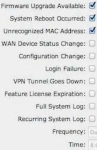
Alerts can be included for the following:
- Firmware Upgrade Available: A firmware update is available for this device.
- System Reboot Occurred: This router has rebooted. This depends on NTP being enabled and available to report the correct time.
- Unrecognized MAC Address: Used with the MAC monitoring lists. An alert is sent when a new unrecognized MAC address is connected to the router.
• WAN Device Status Change: An attached WAN device has changed status. The possible staluses are plugged, unplugged, connected, and disconnected. - Configuration Change: A change to the router configuration.
- Login Failure: A failed login attempt has been detected.
• VPN Tunnel Goes Down: Sends an alert when a VPN tunnel goes down.
• Feature License Expiration: Sends an alert when a feature license is about to expire.
• Full System Log: The system log has filled. This alert contains the contents of the system log. - Recurring System Log: The system log is sent periodically. This alert contains all of the system events since the last recurring alert. It can be scheduled for daily, weekly and monthly reports (Frequency). You also choose the Time you want the alert sent.
SMTP Mail Server
Since your router does not have its own email server, to receive alerts you must enable an SMTP server. This is possible through most email services (Gmail, Yahoo, etc.)
Each SMTP server will have different specifications for setup, so you have to look those up separately. The following is an example using Gmail:
SMTP Mail Server
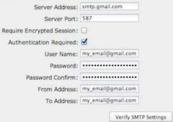
• Server Address: smtp.gmail.com
Server Port: 587 (for TLS, or Transport Layer Security port; the router does not support SSL).
• User Name: Your full email address
• Password: Your Gmail password
• From Address: Your email address
• To Address: Your email address
• Authentication Required: For Gmail, mark this checkbox.
Once you have filled in the information for the SMTP server, click on the "Verify SMTP Settings" button. You should receive a test email at your account.
Delivery Options (Advanced)
Email Subject Prefix: This optional string is prefixed to the alert subject. It can be customized to help you identify alerts from specific routers.
Retry Attempts: The number of attempts made to send an alert to the mail server. After the attempts are exhausted, the alert is discarded.
Retry Delay: The delay between retry attempts.
GPIO Connector
The power connector includes two pins defined for general purpose input and output. These pins are ESD protected. The input tolerance varies between products; see the chart below.
This diagram shows the connector pinout. This is the view into the router (or the rear view of the cable connector):

| Pin Definition COR IBR11x0 COR IBR6x0 Wire Color | ||||
| 1 Ground -- Black | ||||
| 2 Power 9-36 V DC 9-18 V DC Red | ||||
| 3 | Input | 3 V input high threshold (36 V tolerant) | LVTTL digital input with 50K ohm pullup to 3.3 V DC (5 V tolerant) | Orange |
| 4 | Output | capable of sinking 250 mA | LVTTL digital output (capable of source/sink of 50 mA) | Blue |
The wire colors shown are for the power/GPIO cable that is included with the COR IBR1100 and IBR1150 or available as an accessory. Other wiring setups may have different colors.
The GPIO Connector administration page is used to configure these Input and Output General Purpose I/O pins.
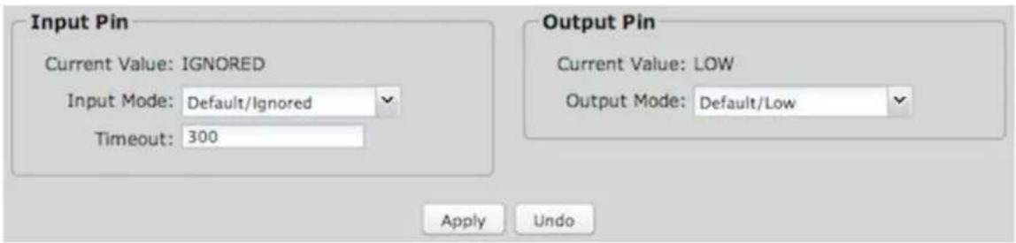
Input Pin
The Input Pin can be used to read a value—either high or low—from an external device and either display that value on this administration page (as the Current Value) or cause the router to reset.
Current Value: Displays HIGH, LOW, or IGNORED.
Input Mode: Select one of the following options from the dropdown menu:
- Default/Ignored: In this mode the input pin is not used.
- Ignition Sensing: In this mode the router will turn off after the input has been held at low for the timeout period (in seconds). The router will then reboot when the input is returned to high. If the input is held low for less than the timeout period before returning to high, no action is taken. (This option is available for the COR IBR1100/IBR1150 only.)
- Input Sensing: In this mode the logic state (high or low) is automatically sensed by the router and is readable as the "Current Value".
- Router Reset: In this mode an external device can reset the router by holding the input low for 10-seconds.
Timeout: When Ignition Sensing is selected, this field sets the number of seconds to wait before the router is powered off. Use Ignition Sensing and Timeout with vehicles. When the vehicle is turned off, the router will stay on for the specified length of time and then shut off (e.g., WiFi stays on for an hour during lunch stops).
Output Pin
The Output Pin can be used to allow an external device to read either whether the router is running or whether the modem is connected.
Current Value: Displays HIGH, LOW, or IGNORED.
Output Mode: Select one of the following options from the dropdown menu:
- Default/Low: In this mode the output pin is not used and is at OV (ground potential).
- Set High/Router Running: In these modes the output pin is logic low while the router is booting and transitions to logic high when the router is fully running. If the router is reset, the output returns to low until the router has fully rebooted.
- Modem Connected: In this mode the output pin is logic low until the modem has connected to a tower. If the connection drops, this output is set low until the connection is restored.
Enterprise Cloud Manager
CradlePoint Enterprise Cloud Manager (ECM) is a cloud-based management service for configuring, monitoring, and organizing your CradlePoint routers. Key features include the following:
• Group based configuration management
• Health monitoring of router connectivity and data usage
• Remote management and control of routers
• Historical record keeping of device logs and status
Visit http://cradlepoint.com/ecm to learn more about CradlePoint ECM. If you do not have ECM credentials, sign up at: http://cradlepoint.com/ecm-signup.
Registering Your Router – Once you have signed up for ECM, click on the Register Router button to begin managing the router through ECM. Input your ECM Username and ECM Password and click Register. You have now registered the device with Enterprise Cloud Manager.
Suspending the ECM Client – Click on the Suspend Client button to stop communication between the device and ECM. Suspending the client will make it stop any current activity and go dormant. It will not attempt to contact the server while suspended. This is a temporary setting that will not survive a router reboot; to disable the client altogether use the Advanced Enterprise Cloud Manager Settings panel (below).
Enterprise Cloud Manager Settings (Advanced)
- Enabled: Enable the ECM client to contact the server. While this box is unchecked, the ECM client will never attempt to contact the server. (Default: Enabled)
• Server Host:Port: The DNS hostname and port number for your ECM server. (Default: stream.cradlepoint.com) - Session Retry Timer: How long to wait, in seconds, before starting a new ECM session following a connection drop or connectivity failure. Note that this value is a starting point for an internal backoff timer that prevents superfluous retries during connectivity loss.
- Unmanaged Checkin Timer: How often, in seconds, the router checks with ECM to see if the router is remotely activated. Note that this value is a starting point for an internal backoff timer that reduces network usage over time.
• Maximum Alerts Buffer: The maximum number of alerts to buffer when offline.
Feature Licenses
Some CradlePoint features may require a license. These features are disabled by default. To obtain a feature license, contact your CradlePoint sales representative.
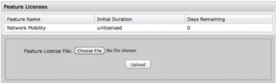
Once you have obtained the feature license file, upload the file to enable the feature. A reboot is required after uploading a feature license file.
Hotspot Services
Any of your networks can be enabled as a hotspot. To enable a hotspot, you need to select a network and set it as a hotspot in Network Settings → WiFi / Local Networks.
NOTE: Although any network can be a hotspot, the router allows only one hotspot.
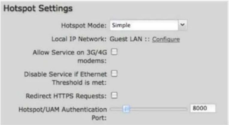
Hotspot Mode Choose from the following dropdown options:
- Simple: Allows "Terms of Use" page and timeout settings controlled within the router.
• RADIUS/UAM: Allows you to set up external authentication servers.
Local IP Network: A single LAN Group – including both WiFi and Ethernet – can be configured as your hotspot. If you do not already have a LAN Group configured as a hotspot, go to the WiFi / Local Networks page (you can click Configure to link to this page) and set the Routing Mode to "Hotspot" for the LAN Group you want to use.
NOTE: Routing Mode is in the Local Network Editor under the IP Settings tab. Select a network in Network Settings → WiFi / Local Networks and click Edit to open the Local Network Editor. The IP Settings tab will already be open. The Routing Mode dropdown menu is at the bottom.
Allow Service on 3G/4G Modems: Allows you to enable or disable hotspot access to the Internet over a modem. This is often used if the router has a main wired link and a secondary modem for failover (typically with a more expensive/limited data plan). Select this option if you want the router to allow data traffic over the modem if the wired connection goes down.
Disable Service if Ethernet Threshold is met: This will block Hotspot use of the WAN when the threshold is met. This can be used if the router is being used as a backup failover connection to another router with a wired connection. If that other router's wired connection goes down and it starts using this router for its primary connection, then disable Hotspot use of the WAN connection. Set the limiting Rate (KB/s) and Time Period (seconds).
Redirect HTTPS Requests: This allows initial requests to HTTPS websites to be redirected appropriately.
Hotspot/UAM Authentication Port: Default: 8000. Type in a different port number, or use the slider to change the port.
Simple Mode Settings
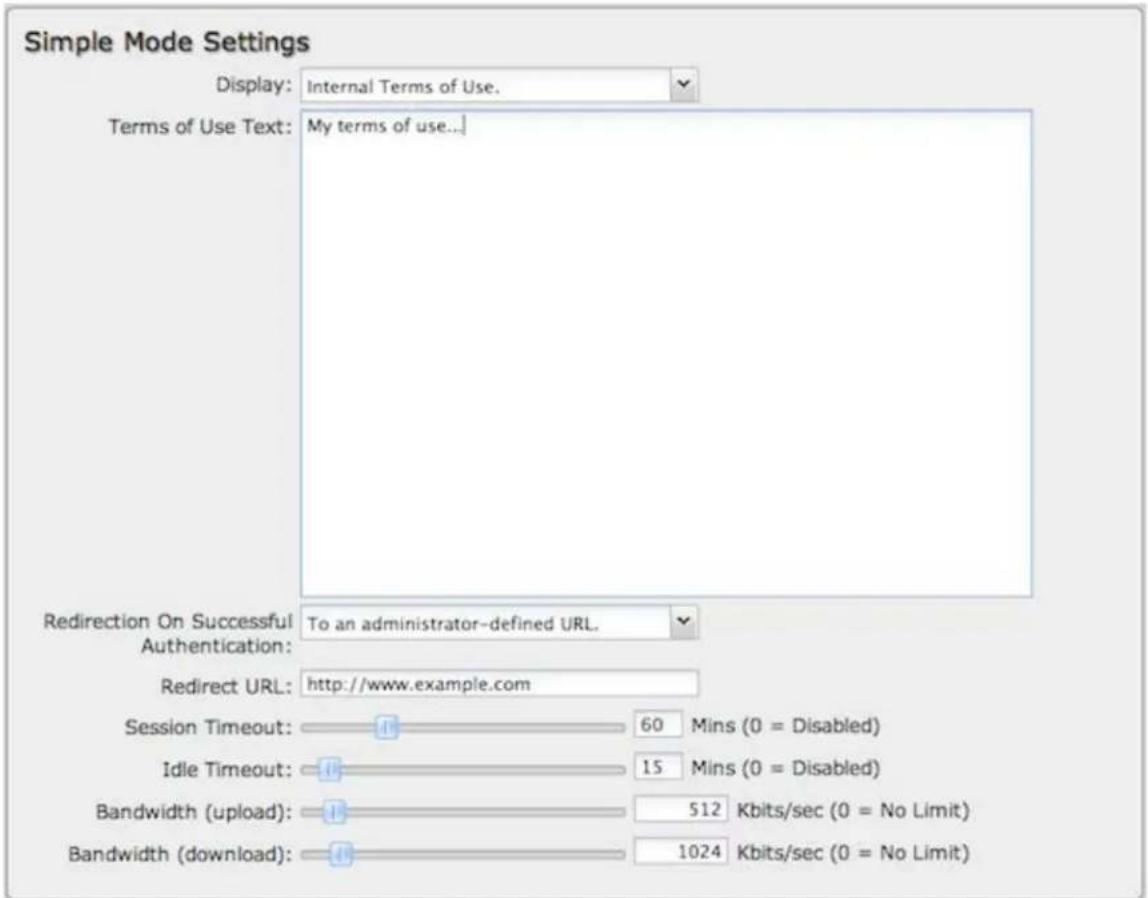
Display: This section allows you to choose if a "Terms of Use" page will be given to the user connecting to the hotspot.
• Internal Terms of Use. Fill in your own terms of use.
- External Terms of Use. Specify a URL that has the Terms of Use page. Users will automatically be directed to this page.
• No Terms of Use. Redirect Only.
Redirection on Successful Authentication: Depending on your choice for the "Terms of Use" page, your have further options for where the user will be directed. After the user accepts the terms, you can either let him/her continue to the URL they were trying to reach or you can force the user to go to a specified URL once before continuing on.
• To the URL the user intended to visit.
• To an administrator-defined URL.
Redirect URL: If you have chosen to send users to an administrator-defined URL, you will need to specify the address.
Session Timeout (Default: 60 minutes.) The amount of time the user may use the router before being forced to authenticate again.
Idle Timeout: (Default 15 minutes.) If the user is idle for this amount of time, make them re-authenticate.
Bandwidth (upload): (Default: 512 Kbits/sec.) The data rate limit for users uploading data through the hotspot.
Bandwidth (download): (Default: 1024 Kbits/sec.) The data rate limit for users downloading data through the hotspot.
RADIUS/UAM Settings
This section allows you to configure a RADIUS and Universal Access Method server. After the user accepts the terms, you can either let him/her continue to the URL they were trying to reach or you can force the user to go to a specified UAM Server or URL once before continuing on.
RADIUS Settings
RADIUS Settings
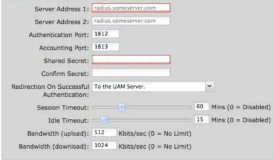
• Server Address 1: Assigned by RADIUS service.
• Server Address 2: This is an optional backup server.
• Authentication Port: The standard port number, 1812, will usually be sufficient.
• Accounting Port: The standard port number, 1813, will usually be sufficient.
• Shared Secret. Assigned by RADIUS service.
- Redirection On Successful Authentication: Choose from the dropdown list of options for redirection.
- Redirect to the UAM Server.
- Redirect to the URL that the user intends to visit.
-
Redirect to the following URL (input the desired URL).
-
Session Timeout: (Default: 60 minutes.) The amount of time the user may use the router before being forced to authenticate again. This value can be overwritten by the RADIUS server.
- Idle Timeout: (Default: 15 minutes.) If the user is idle for this amount of time, make them re-authenticate.
• Bandwidth (upload): (Default: 512 Kbits/sec.) The data rate limit for users uploading data through the hotspot.
• Bandwidth (download): (Default: 1024 Kbits/sec.) The data rate limit for users downloading data through the hotspot.
UAM Settings
UAM Settings
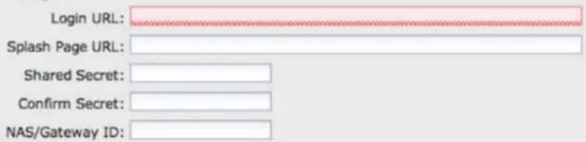
- Login URL: Assigned by UAM service.
- Splash Page URL: Optional URL that can point to an external page that can provide specific information to the user prior to being authenticated. The page MUST provide a link back to the Login URL in order for the user to be authenticated. For example: http://lan ip address:uam port/prelogin or http://192.168.10.1:8000/prelogin.
• Shared Secret: Optional, depending on the UAM service.
• NAS/Gateway ID: Assigned by UAM service.
HeartBeat Settings

The HeartBeat, when enabled, sends the following information to the specified URL at the specified time interval so the operator managing the hotspot knows if the router is still functioning:
• mac: The MAC address of the router, i.e. 00-11-22-33-44-55.
- nasid: The NAS/Gateway ID of the router which should be entered in the UAM Settings.
- os_date: A string showing the type of router and the firmware version running, e.g. Cradlepoint_4.1.2.
• uptime: The uptime and system load average of the router
Allowed Hosts Prior to Authentication
Adding hostnames to this list will allow access from your network to any external domain or website prior to being authenticated. For example, a hotel might allow access to its own website prior to authentication.
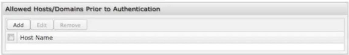
Click Add to enter new hostnames you wish to allow.
Enter the hostname or domain name of the website you wish to allow, e.g. www.company.com or company.com. To allow all domain and sub-domain options, use a wildcard, e.g. *.company.com.
Click Submit to save your additions.
Authorized MAC Addresses
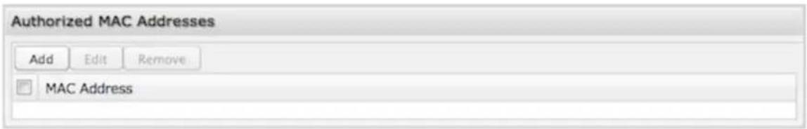
Add the MAC addresses of trusted machines. This gives them automatic access through the Hotspot portal.
Serial Redirector
A single USB Serial device can be used to establish a serial link to a host port on the router. The USB Serial device can also be accessed by running "serial" from an SSH session.
Telnet to Serial Configuration
Telnet to Serial Configuration
Server Status: Disabled
Enabled:
LAN:
Authenticated LAN: √
WAN: □
Server Port: 7218
- Enabled: Enabling Telnet to Serial will start a Telnet server that passes its connection to the serial adapter. Enabling this service is not necessary when accessing serial through SSH.
• LAN: Enable serial redirector for LAN connections. - Authenticated LAN: Enable serial redirector for Authenticated LAN connections. You must be logged into the router to use the redirector.
• WAN: Enable serial redirector for WAN connections.
• Server Port: Enter a port number for the redirector to use. (Default: 7218)
USB Serial Adapter Configuration
USB Serial Adapter Configuration
Baud Rate: 9600
Byte Size: 8 Bits
Parity: None
Stop Bits: 1
Hardware (RTS/CTS): □
Software (XON/XOFF): √
Linefeed: CR
• Baud Rate: Select from the dropdown list.
50
。75
。 110
134
150
200
300
600
1200
1800
2400
4800
9600
19200
• Byte Size: The number of bits in a byte. Select from: 5, 6, 7, and 8.
- Parity: Change this value to enable parity bit checking. Select from the following dropdown options:
- None: No parity checking. (Default)
- Even: parity bit will always be even.
- Odd: parity bit will always be odd.
-
Mark: parity bit will always be odd and always 1.
• Space: parity bit will always be even and always 0. -
Stop Bits: Number of bits to initiate the stop period. Select from these dropdown values: 1, 1.5, and 2.
- Hardware (RTS/CTS): Use RTS (Request To Send)/CTS (Clear To Send) to enable flow control.
• Software (XON/XOFF): Use XON/XOFF to enable flow control. -
Linefeed: Select how you want linefeeds translated (CR = carriage return and LF = line feed).
-
Ignore
CR/LF - CR
。LF
SNMP Configuration
SNMP, or Simple Network Management Protocol, is an Internet standard protocol for remote management. You might use this instead of Enterprise Cloud Manager if you want to remotely manage a set of routers that include both CradlePoint and non-CradlePoint products.
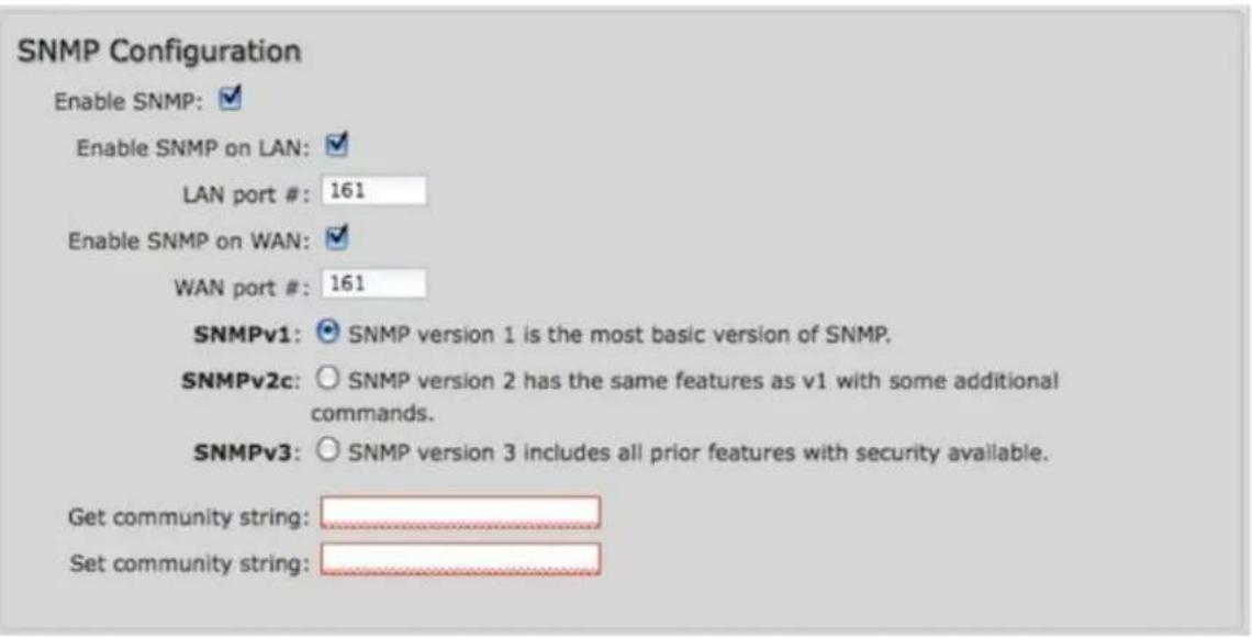
- Enable SNMP: Selecting "Enable SNMP" will reveal the router's SNMP configuration options.
- Enable SNMP on LAN: Enabling SNMP on LAN will make SNMP services available on the LAN networks provided by this router. SNMP will not be available on guest or virtual networks that do not have administrative access.
• LAN port #: Use the LAN port # field to configure the LAN port number you wish to access SNMP services on. (Default: 161) - Enable SNMP on WAN: Enabling SNMP on WAN will make SNMP services available to the WAN interfaces of the router.
- WAN port #: Use the WAN port # field to configure which publicly accessible port you wish to make SNMP services available on. (Default: 161)
- SNMPv1: SNMP version 1 is the most basic version of SNMP. SNMPv1 will configure the router to transmit with settings compatible with SNMP version 1 protocols.
- SNMPv2c: SNMP version 2c has the same features as v1 with some additional commands. SNMPv2c will configure the router to use settings and data formatting compatible with SNMP version 2c.
- SNMPv3: SNMP version 3 includes all prior features with security available. SNMPv3 is the most secure setting for SNMP. If you wish to configure traps then you must use SNMP version 3.
- Get community string: The "Get community string" is used to read SNMP information from the router. This string is like a password that is transmitted in regular text with no protection.
- Set community string: The "Set community string" is used when writing SNMP settings to the router. This string is like a password. It is a good idea to make it different than the "Get community string."
SNMPv3
If you select SNMPv3, you have several additional configuration options for added security.
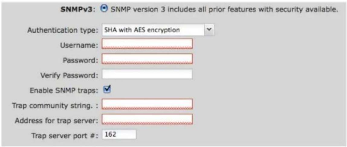
- Authentication type: Select the authentication and encryption type that will be used when connecting to the router from the following dropdown list. These settings must match the configuration used on any SNMP clients.
- MD5 with no encryption
- SHA with no encryption
- MD5 with DES encryption
- SHA with DES encryption
- MD5 with AES encryption
-
SHA with AES encryption
-
Username: Enter the Username configured on your SNMP host in the username field.
- Password: Enter the Password for your SNMP host in the password and verify password fields. This password must be at least 8 characters long
- Enable SNMP traps: Enabling traps will allow you to configure a destination server, community, and port for trap notifications. Trap notifications are returned to the server with SNMPv1.
- Trap community string: The trap notifications will be returned to the trap server using this SNMPv1 trap community name.
- Address for trap server: Enter the address of the host system that you want trap alerts sent to.
- Trap server port #: Enter the port number that the remote host will be listening for trap alerts on. (Default: 162)
System Information
System information via SNMP is Read-Writable by default. However, if a value is set here, that field will become Read-Only.
• System Contact: Input the email address of the system administrator.
• System Name: Input the router's hostname.
- System Location: Input the physical location of the router. This is simply a string for your own information.
System Control
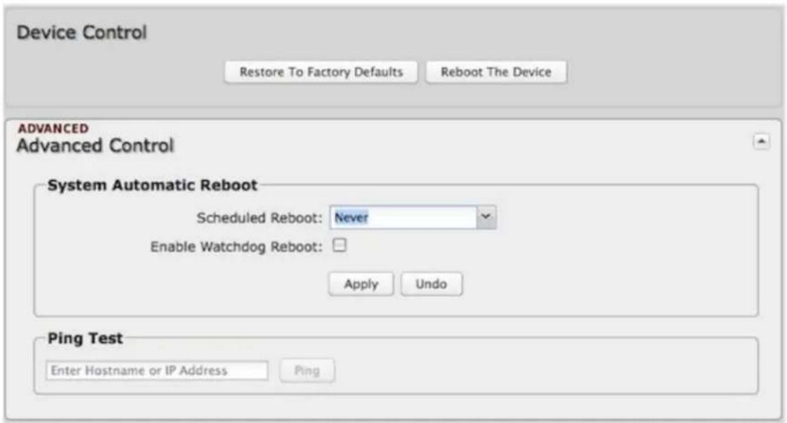
Restore to Factory Defaults: This changes all settings back to their default values.
Reboot The Device: This causes the router to restart.
Advanced Control: System Automatic Reboot, Ping Test
Scheduled Reboot: This causes the router to restart at a user-determined time.
Watchdog Reboot: This causes the router to automatically restart when it determines an unrecoverable error condition has occurred.
Ping Test: A simple test to check Internet connectivity. Type the Hostname or IP address of the computer you want to ping and press 'Enter' or click the 'Ping' button.
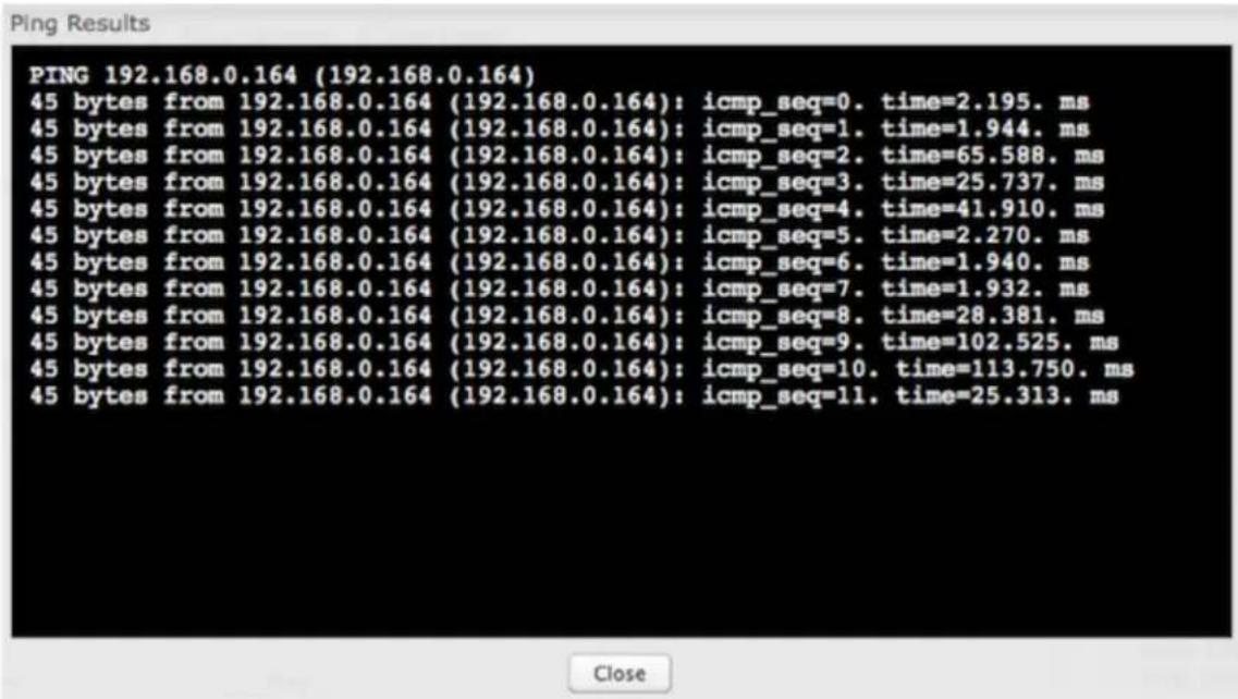
System Software
This allows the administrator to load new firmware onto the router to add new features or fix defects. If you are happy with the operation of the router, you may not want to
upgrade just because a new version is available. Check the firmware release notes (cradlepoint.com/firmware) for information to decide if you should upgrade.
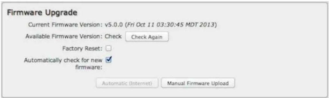
- Current Firmware Version: Shows the number of the current firmware and the date it was updated.
- Available Firmware Version: If there is a new firmware version available, this will list the version number. Click "Check Again" to have the router check the newest firmware.
- Factory Reset: Set default settings to match the new firmware. This is safest, as settings may have changed. You should back up your current settings and restore them after the new firmware is loaded.
• Automatically check for new firmware: Check for an available firmware update once a day.
• Automatic (Internet): Have the router download the file and perform the upgrade with no user interaction. - Manual Firmware Upload: Upload the router firmware from an attached computer. (Go to cradlepoint.com/firmware to download the firmware.)
System Config Save/Restore
- Backup Current Settings: Click on "Save to disk" to save your current settings to a file on a computer.
- Restore Settings: Click on "Upload from file" to restore your previous settings from a file on a computer.
System Config Save/Restore

Firmware Upgrade and System Config Restore
Load new firmware and restore your previous settings from a file on a computer without rebooting between steps.
Firmware Upgrade and System Config Restore
Select Files: Upload from file