e-medic 22AM+ - Suivi médical Baaske Medical - Free user manual and instructions
Find the device manual for free e-medic 22AM+ Baaske Medical in PDF.

User questions about e-medic 22AM+ Baaske Medical
0 question about this device. Answer the ones you know or ask your own.
Ask a new question about this device
Download the instructions for your Suivi médical in PDF format for free! Find your manual e-medic 22AM+ - Baaske Medical and take your electronic device back in hand. On this page are published all the documents necessary for the use of your device. e-medic 22AM+ by Baaske Medical.
USER MANUAL e-medic 22AM+ Baaske Medical
text_image
22AM+ | 22AM+ Touch 24AM+ | 24AM+ Touch 27AM+ | 27AM+ TouchMANUAL
Introduction 3
Product overview 4
Important information 8
Equipment Symbols 13
Cleaning the display 15
EMC notice 16
Monitor installation 20
Daily operation 24
OSD menu operation 25
Contact informations 43
© 2018 Baaske Medical GmbH & Co.KG. All rights reserved.
Information in this document has been carefully checked for accuracy; however, no guarantee is given to the correctness of the contents. Photographs and schematic diagrams used in this document are for illustration purposes only. The actual product may vary. This document contains proprietary information protected by copyright. No part of this manual may be reproduced by any mechanical, electronic, or other means, in any form, without prior written permission of Baaske Medical.
This document is subject to change without notice.
1. Introduction
1.1 Monitor description
The equipment is applied for healthcare that is intended for general use in hospital environment for data collection and display for reference. It shall not be used with life support system or for medical diagnosis.
Type of equipment: Portable (on a table)
Intended location: Medical environment
Intended User Profile
| Age: Adult (Age above 21) | |
| Gender: Can be use by all genders | |
| Linguistik/ Cultural Background: At least English | |
| Education/ Professional Competence: | General level of education |
| Intended User Group: Hospital staff | |
| Knowledge Base: User should possess basic medical knowledge |
1.2 Box of contents
| LCD Touch Screen Monitor/ LCD Monitor |
| User Guide |
| AC Power Cord |
| VGA Cable |
| DVI or HDMI Cable |
| USB Cable (for touch version) |
| Power Adapter (Delta 24V) |
optional
| Audio Cable |
| RS232 Cable |
| DP Cable |
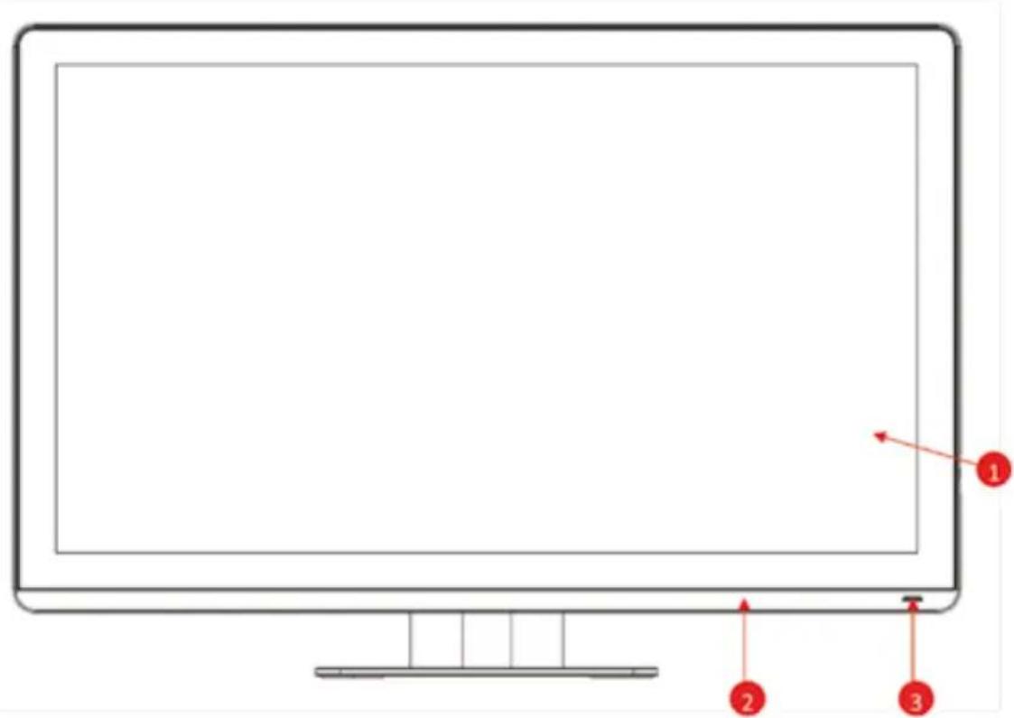
1.3 Product overview
Front View
The image below shows the front view of the display.
text_image
Diagram of a computer monitor with labeled parts 1, 2, and 3 pointing to its screen area.Image 1-1 Front view
- P-CAP touch (for touch version) / Cover glass
- Bezel
- LED
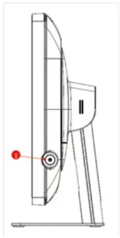
Side View
The image below shows the control keys located in the right bottom corner of the display.
natural_image
Technical line drawing of a mechanical component with a red indicator point and label (no readable text or symbols)Image 1-2 Control Key
- Menu/ Enter key/ Scrolling key
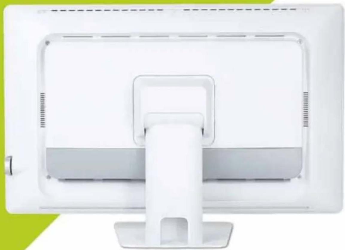
Rear View
text_image
Technical diagram of a mechanical assembly with numbered components and directional arrows indicating flow or movement.Image 1-3 Rear view
- Rear cover
2.10 cover
3 Monitor stand - Hinge cover
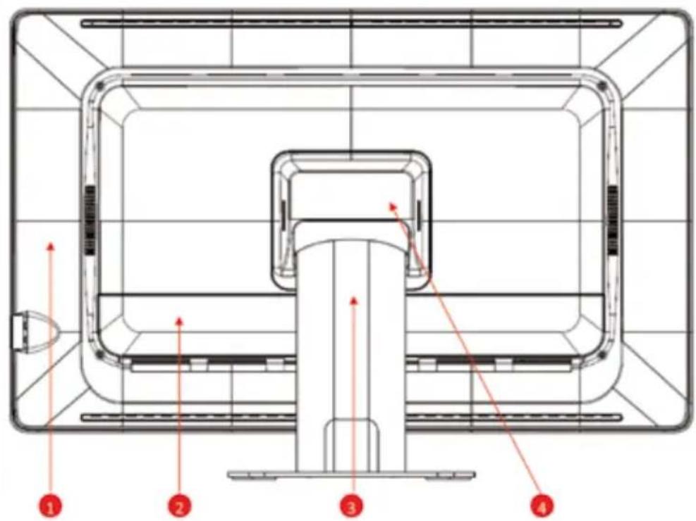
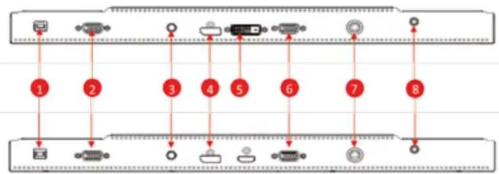
Available Connections
flowchart
graph TD
    A["1"] --> B["2"]
    B --> C["3"]
    C --> D["4"]
    D --> E["5"]
    E --> F["6"]
    F --> G["7"]
    G --> H["8"]
    style A fill:#f9f,stroke:#333
    style B fill:#ccf,stroke:#333
    style C fill:#cfc,stroke:#333
    style D fill:#fcc,stroke:#333
    style E fill:#cff,stroke:#333
    style F fill:#ffc,stroke:#333
    style G fill:#cfc,stroke:#333
    style H fill:#fcc,stroke:#333
Image 1-4 Available connections (bottom view)
- USB (Touch)
- RS232 (Touch)
-
Audio
-
Display Port
-
DVI
-
VGA
-
Power
8.

2. Important information
2.1 Safety information
General recommendations
Read the safety and operating instructions before operating the device. Save the safety and operating instructions for future reference.
Adhere to all warnings on the device and in the operating instructions manual. Follow all instructions for operation and use.
Electrical Shock or Fire Hazard
To prevent an electrical shock or fire hazard, do not remove the cover. No serviceable parts are inside. Refer servicing to qualified personnel. Do not expose this apparatus to rain or moisture.
Modifications to the unit:
Do not modify this equipment without authorization of the manufacturer.
Degree of safety (flammable anesthetic mixture):
Equipment is not suitable for use in the presence of a flammable anesthetic mixture of air, oxygen, or nitrous oxide.
Non-patient care equipment
- Equipment primarily for use in a health care facility. It is intended for use when contact with a patient is unlikely (no applied part).
- The equipment may not be used with life support equipment.
- The user should not touch the equipment, nor its signal input ports (SIP)/signal output ports (SOP) and the patient at the same time.
Mission critical applications
We strongly recommend for there to be a replacement monitor immediately available in mission critical applications.
Power connection – Equipment with internal power supply
- This equipment must be grounded.
- Power requirements: The equipment must be powered by the
DC mains voltage.
- The equipment is intended for continuous operation.
Power cords:
- Do not overload wall outlets and extension cords as this may result in fire or electric shock.
- Main leads protection (U.S.: Power cord): Power cords should be routed so that they are not walked upon or pinched by items placed upon or against them. Pay particular attention to cords at plugs and receptacles.
- The power supply cord should be replaced by the designated operator only at all time.
- Use a power cord that matches the voltage of the power outlet, which should be approved and in compliance with the safety standard of your particular country.
- Avoid placing the monitor near places that is hard to reach or difficult to disconnect the power supply cord.
- WARNING: To avoid risk of electric shock, this equipment must only be connected to a supply mains with protective ground.
Grounding reliability
Grounding reliability can only be achieved when the equipment is connected to an equivalent receptacle.
Liquids and moisture
Never expose the monitor to liquids or moisture.
Never use the monitor near water - e.g. near a bathtub, washbasin, swimming pool, kitchen sink, laundry tub or in a wet basement.
Ventilation
Do not cover or block any ventilation openings in the cover of the set.
When installing the device in a cupboard or another closed location, heed the necessary space between the set and the sides of the cupboard.
Installation
Place the device on a flat, solid, and stable surface that can support the weight of at least 3 devices. If you use an unstable cart or stand, the device may fall, causing serious injury to a child or adult, and serious damage to the device.
Accessory equipment connected to the analog and digital interfaces must be in compliance with the respective nationally harmonized IEC standards (i.e. IEC 60601-1 for medical equipment.) Furthermore all configurations shall comply with the system standard in IEC 60601-1. Anyone who connects additional equipment to the signal input part or signal output part is configuring a medical system, and is therefore, responsible that the system complies with the requirements of the system standard IEC 60601-1. The unit is for exclusive interconnection with IEC 60601-1 certified equipment in the patient environment 60XXX certified equipment outside of the patient environment.
This apparatus conforms to:
EN 60601-1:2006+A11:2011+A1:2013+A12:2014 IEC 60601-1: 2005 + CORR. 1 (2006) + CORR. 2 (2007) + AM1(2012) ANSI/AAMI ES60601-1:2005+A2(R2012)+A1 CAN/CSA-C22.2 No. 60601-1:14 EN 60601-1-2 (2015) IEC 60601-1-2 (2014) FCC CFR 47 Part 15 Subpart B (Level B) RoHS (2011/65/EU & 2015/863/EU)
2.2 Environmental information
Disposal Information
Waste Electrical and Electronic Equipment

This symbol on the product indicates that under the European Directive 2012/19/EU, governing waste from electrical and
electronic equipment, this product must not be disposed of with other municipal waste. Please dispose of your waste equipment by handing it over to a designated collection point for the recycling of waste electrical and electronic equipment. To prevent possible harm
to the environment or human health from uncontrolled waste disposal, please separate these items from other types of waste and recycle them responsibly to promote the sustainable reuse of material resources.
For more information about recycling of this product, please contact your local city office orm your municipal waste disposal service.
2.3 Regulatory information
Indications for use
The monitor is applied for healthcare that is intended for general use in hospital environment for data collection and display for reference.
FCC class B
This device complies with Part 15 of the FCC Rules. Operation is subject to the following two conditions:
(1) This device may not cause harmful interference, and (2) this device
must accept any interference received, including interference that may cause undesired operation. This device has been tested
and found to comply with the limits for a Class B digital device, pursuant to Part 15 of the FCC Rules. These limits are designed to provide reasonable protection against harmful interference in a residential installation. This device generates uses and can radiate radio
frequency energy and, if not installed and used in accordance with
the instructions, may cause harmful interference to radio communica-
tions. However, there is no guarantee that interference will not occur in a particular installation. If this device does cause harmful interference
to radio or television reception, which can be determined by turning
the device off and on, the user is encouraged to try to correct the interference by one or more of the following measures:
- Reorient or relocate the receiving antenna.
- Increase the separation between the device and receiver.
- Connect the device to an outlet on a circuit different from that to which the receiver is connected.
- Consult the dealer or an experienced radio/TV technician for help.
Changes or modifications not expressly approved by the party responsible for compliance could void the user's authority to operate the equipment.
Canadian notice
This ISM device complies with Canadian ICES-003.
2.4 Equipment Symbols
Electrical and electronic equipment symbols

Indicates the device meets the requirements of the applicable EC directives.

Indicates compliance with Part 15 of the FCC rules (Class A or Class B)

Indicates the device is approved according to the TUV regulations for Canada and US
Indicates the USB connectors on the device

Indicates the Display Port connectors on the device.

Indicates the legal manufacturer

Indicates the manufacturing date
Indicates the temperature limitations for the device to safely operate within specs.

Indicates the device serial number.

Indicates the devicepart number or catalog number.
Warning: dangerous voltage.

Caution

Consult the operating instructions

text_image
Electrical circuit symbols and power rating diagram with Chinese characters and line representationsIndicates this device must not be thrown in the trash but must be recycled, according to the European WEEE (Waste Electrical and Electronic Equipment) directive
Indicates Direct Current (DC)
Indicates Alternating Current (AC)
Stand-by
Power ON. Power connection to the mains
Power OFF
Protective earth (ground)
Equipotentiality. Connect device to a potential equalization conductor.
3. Cleaning the display
3.1 Cleaning instructions
To clean the display
Cleaning the display using a sponge, cleaning cloth, or soft tissue with lightly moistened recognized cleaning product for medical equipment. Read and follow all labeled instructions on the cleaning product. In case of doubt about a certain cleaning product, use plain water.
CAUTION:
• Take care not to damage or scratch the front glass or LCD. Be careful with rings or other jewelry and do not apply excessive pressure on front glass or LCD.
- Do not apply or spray liquid directly to the display as excess liquid may cause damage to internal electronics. Instead, apply the liquid to a cleaning sponge, cloth, or tissue.
3.2 EMC notice
Electromagnetic emissions
The monitor is intended for use in the electromagnetic environment specified below. The customer or the user of the monitor should assure that it is used in such an environment.
| Emissions test Compliance | Electromagnetic environment – Guidance | |
| RF emissionsCISPR 11 | Group 1 The monitor uses | RF energy only forits internal function. Therefore, its RF emissions are very low and are not likely to cause any interference with nearby electronic equipment. |
| RF emissionsCISPR 11 | Class B | The monitor is suitable for use in all establishments, including domestic establishments and those directly connected to the public low voltage power supply network that supplies buildings used for domestic purposes. |
| Harmonic emissionsIEC 61000-3-2 | N/A (power consumption less than 75W) | |
| Voltage fluctuations/ flicker emissions IEC 61000-3-3 | Complies | |
This monitor complies with appropriate medical EMC standards on emissions to, and interference from surrounding equipment. Operation is subject to the following two conditions:
(1) this device may not cause harmful interference, and (2) this device must accept any interference received, including interference that may cause undesired operation.
Interference can be determined by turning the equipment off and on.
If this equipment does cause harmful interference to, or suffer from harmful interference.
rence of, surrounding equipment, the user is encouraged to try to correct the interference by one or more of the following measures:
- Reorient or relocate the receiving antenna or equipment.
- Increase the separation between the equipment and receiver.
- Connect the equipment into an outlet on a circuit different from that to which the receiver is connected.
- Consult the dealer or an experienced technician for help.
Electromagnetic immunity
The monitor is intended for use in the electromagnetic environment specified below. The customer or the user of the monitor should assure that it is used in such an environment.
| Immunity test IEC 60601 | Test levels Compliance level | Electromagnetic | environment – guidance |
| Electrostatic discharge (ESD)IEC 61000-4-2 | ±8kV contact±15kV air | ±8kV contact±15kV air | Floors should be wood, concrete or ceramic tile. If floors are covered with synthetic material, the relative humidity should be at least 30 % |
| Electrical fast transient/burst IEC 61000-4-4 | ±2kV for power supply lines±1kV for input/output lines | ±2kV for power supply lines±1kV for input/output lines | Mains power quality should be that of a typical commercial or hospital environment |
| SurgeIEC61000-4-5 | ±1 kV line(s) to line(s)±2 kV line(s) to earth | ±1 kV line(s) to line(s)±2 kV line(s) to earth | Mains power quality should be that of a typical commercial or hospital environment |
| Voltage dips, short interruptions and voltage variations on power supply input linesIEC 61000-4-11 | 0% residual voltage for 0.5 cycle.0% residual voltage for 1 cycle.70% residual voltage for, 0.5s.0% residual voltage for 5s. | 0% residual voltage for 0.5 cycle.0% residual voltage for 1 cycle.70% residual voltage for, 0.5s.0% residual voltage for 5s. | Mains power quality should by that of a typical commercial or hospital environment. If the user of the RGP2422AMI requires continued operation during power mains interruptions, it is recommended that the RGP2422AMI be powered from an uninterruptible power supply or a battery. |
| Power frequency (50/60 Hz) magnetic field IEC 61000-4-8 | 30 A/m Not applicable | Power frequency | magnetic fields should be at levels characteristic of a typical location in a typical commercial or hospital environment. |
| Conducted RFIEC 61000-4-6Radiated RFIEC 61000-4-3 | 3 V at 0,15 - 80MHz6 V at ISM bands10 V/m at 80-2,700MHz.And 9-28V/m at 385-6,000MHz, Pulse Mode:27 V/m at 385MHz28 V/m at 450MHz9V/m at710/745/780MHz28 V/m at810/870/930MHz28 V/m at1720/1845/1970MHz28 V/m at 2450MHz9V/m at5240/5500/5785MHz | 3 V at 0,15 - 80MHz6 V at ISM bands10V/m at 80-2,700MHz.And 9-28V/m at 385-6,000MHz, Pulse Mode:27 V/m at 385MHz28 V/m at 450MHz9V/m at710/745/780MHz28 V/m at810/870/930MHz28 V/m at1720/2450MHz9V/m at5240/5500/5785MHz | Portable and mobile RF communications equipment should be used no closer to any part of the monitor, including cables, than the recommend separation distance calculated from the equation applicable to the frequency of the transmitter. Recommended separation distanced = 1.2VPd = 1.2VP 80 MHz to 800 MHzd = 2.3VP 800 MHz to 2.5 GhzWhere P is the maximum output power rating of the transmitter in watts (W) according to the transmitter manufacturer and d is the recommended separation distance in meters (m).Field strengths from fixed RF transmitters, as determined by an electromagnetic site survey,5should be less than the compliance level in each frequency range.5Interference may occur in the vicinity of equipment marked with symbol:[IMAGE] |

At 80 MHz and 800 MHz, the higher frequency range applies.

These guidelines may not apply in all situations. Electromagnetic propagation is affected by absorption and reflection from structures, objects, and people.
Recommended separation distance
The monitor is intended for use in an electromagnetic environment in which radiated RF disturbances are controlled. The customer of the user of the monitor can help prevent electromagnetic interference by maintaining a minimum distance between portable and mobile RF communica-
tions equipment (transmitters) and the monitor as recommended below, according to the maximum output power of the communications equipment.
| Rated maximum output power of transmitter W | Separation distance according to frequency of transmitter | ||
| 150kHz to 80MHz d=1.2VP | 80MHz to 800MHz d=1.2VP | 800MHz to 2.5GHz d=2.3VP | |
| 0.01 0.12 0.12 0.23 | |||
| 0.1 0.38 0.38 0.73 | |||
| 1 1.2 1.2 2.3 | |||
| 10 3.8 3.8 7.3 | |||
| 100 12 12 23 | |||

At 80 MHz and 800 MHz, the separation distance for the higher frequency range applies.
These guidelines may not apply in all situations. Electromagnetic propagation is affected by absorption and reflection form structures, object and people.
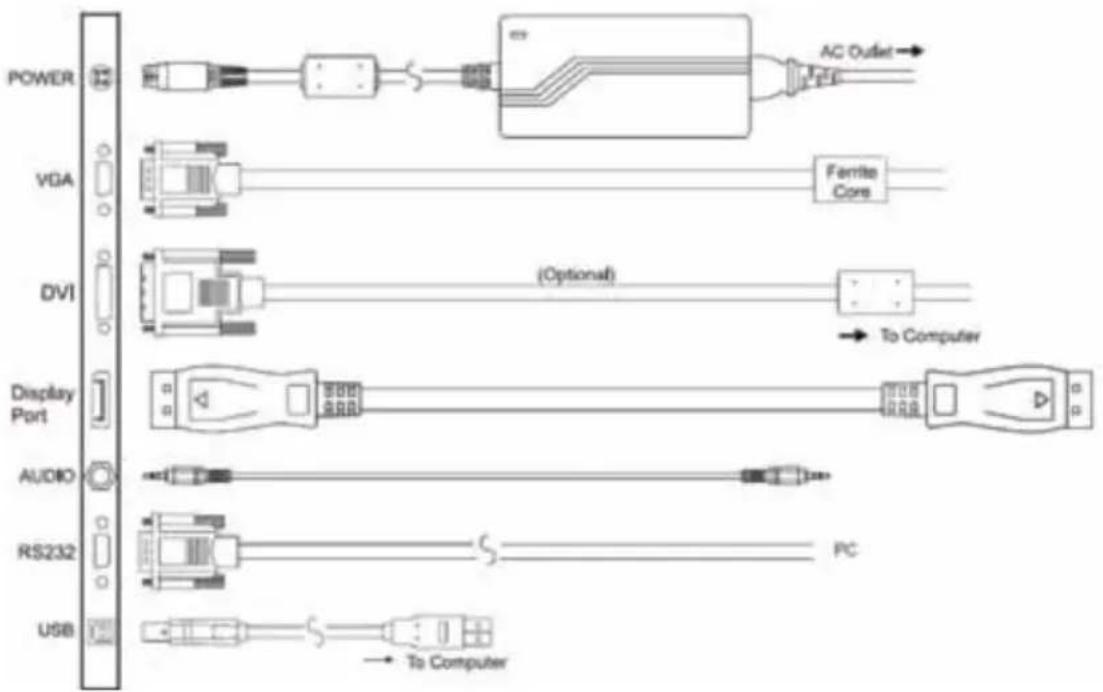
4. Monitor installation
| WARNING | |
| Sufficient expertise is required to install this equipment. All devices and complete setup must be tested before operation. | |
4.1 Installation procedure
To install your monitor
To get access to the connectors, put the display on a flat surface.
- Connect one or more video source(s) to the corresponding video inputs of the monitor.
Use the appropriate video cable(s) to do this.
- Connect the USB or RS232 connector for touch screen function.
-
Connect the Audio cable for audio function.
-
Connect the power cord input to a power adapter with a grounded Power Outlet.
-
Connect the power adapter input to the monitor.
-
Install cable cover back on the monitor.
flowchart
graph LR
    POWER --> AC["AC Outlet"]
    VGA --> FiniteCore["Ferrite Core"]
    DVI --> (Optional)(Optional) --> ToComputer["To Computer"]
    DisplayPort --> ToComputer
    AUDIO --> ToComputer
    RS232 --> ToComputer
    USB --> ToComputer
    AC --> ToComputer
    FiniteCore --> ToComputer
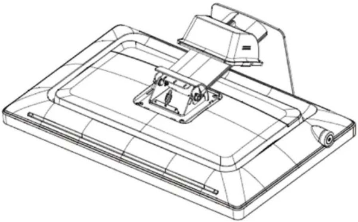
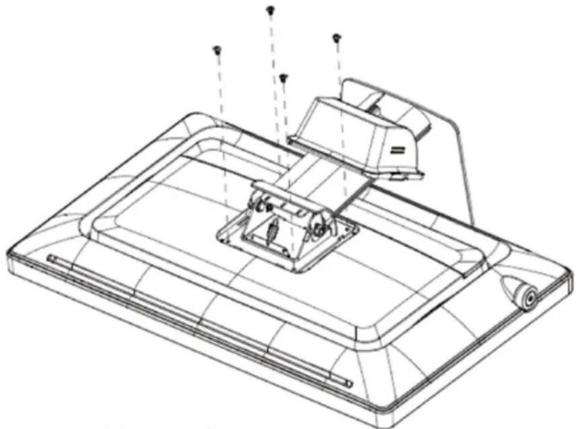
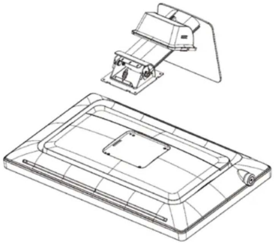
4.2 Stand removal & VESA mount installation
This monitor provided with a validated stand. The monitor has been designed to be used in landscape position with a maximum tilt of -5^ to
30° backward. If a different stand is needed in the final application, the
monitor VESA interface (VESA 100 mm standard) could be used.
To remove the stand and install the VESA mount
-
Place the monitor face down on a flat, solid and stable surface.
-
Remove the hinge cover
-
Unscrew the 4x M4 (length: 10mm) screws fixing the stand and rear cover
-
Remove the stand and install the VESA mount.
Caution: Use a protective cloth or cushion to prevent the monitor and LCD from any damage or scratches.
Tip: Store the fixation screws at a known place for possible future use.
natural_image
Technical line drawing of a mechanical device with mounting bracket and internal components (no text or symbols)Image 4-2-1 Remove the hinge cover
natural_image
Technical line drawing of a flat-screen printer or scanner device with no visible text or symbolsImage 4-2-2 Remove the 4x M4 screws
natural_image
Technical line drawing of a device with two views: top shows internal components, bottom shows top-down view (no text or symbols)Image 4-2-2 Remove the 4x M4 screws
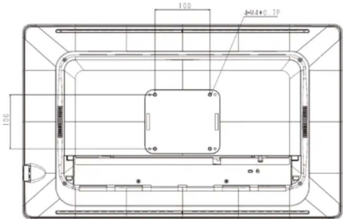
- Attach the monitor in landscape position to a 100 mm VESA mounting bracket. Mounting in portrait position is not feasible.
text_image
100 4-M4+0.7P 100Image 4-2-4 VESA mount is located at the back of the monitor.
5. Daily operation
5.1 Main power switch
The monitor is switched on or off with the main switch, sees image 1-2 (page 5) Control key.
5.2 Power/Status indication
During start-up the monitor performs signal detection before going into normal operation mode. Depending on the detection result, the status LED on the side of the monitor will show different LED color.
Below is an overview of the possible status LED modes:
| LED Color Status LED modes Operation Description | ||
| OFF (No LED) OFF mode Monitor is not powered. | ||
| Blue, static Normal mode Monitor is ON, video sync OK. | ||
| Red, static Stand-by mode(Power saving) | Automatically enters power saving and standing by for input signal | |
6. OSD menu operation
The Charts displays the function tree and brief explanations of the functions.
Color, OSD, and other adjustments have submenus under each tree.
6.1 On-Screen Display
The LCD monitor features an On-Screen Display (OSD) menu with easily identifiable icons designed to make adjustment of your monitor display settings a more user-friendly process. When highlighted, the icon illustrates the control function and brief instruction to assist the user in identifying which control needs adjustment.
The OSD menu is activated by pressing the Control Dial inward and you can select and adjust the function of your choice by rotating and clicking the Control Dial. The main menu displays a list of submenu icons and the current video input mode. Rotate the dial to move the highlights to the control you would like to adjust, then press the Control Dial inward to select that control or to activate that function. Depending on the control you selected, a submenu of the control with a status bar will appear. The status bar indicates in which direction, form the factory preset; your adjustments are being made. Rotate the Control Dial to adjust the control.
When you have finished making the adjustments, the setting is saved automatically by activating the control function. If you do not touch the Control Dial for 30 seconds, the OSD is automatically exited saving your current settings.
6.2 Menu Descriptions
The LCD monitor is capable of accepting VGA, DVI (or HDMI), Display Port signal inputs and therefore has two different sets of OSD control functions.
Because the digital signaling always achieves optimum display quality without mush adjustment, it requires much less OSD functions than the analog input mode. The following options are not available in digital input mode:
Auto Setup, Display, Clock/Phase, denoted by as trick (*) in the following descriptions. If switched to digital input model, you will encounter a “Not Available” message.
6.3 OSD Structure
flowchart
graph TD
    A["MAIN MENU"] --> B["Exit"]
    A --> C["Auto Setup"]
    A --> D["Brightness"]
    D --> E["0-100"]
    A --> F["Contrast"]
    F --> G["0-100"]
    A --> H["Display"]
    H --> I["Color Mode"]
    H --> J["Clock/Phase"]
    H --> K["Audio"]
    H --> L["Management"]
    H --> M["Operating Hours"]

    N["Auto Setup"] --> O["Exit"]
    N --> P["Yes"]
    N --> Q["No"]

    R["Display"] --> S["Exit"]
    R --> T["H. Position"]
    R --> U["V. Position"]
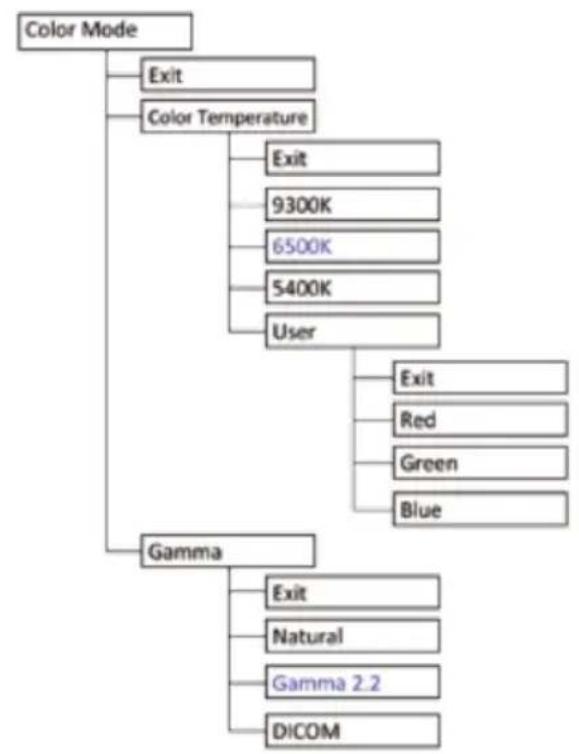
flowchart
graph TD
    A["Color Mode"] --> B["Exit"]
    A --> C["Color Temperature"]
    C --> D["Exit"]
    C --> E["9300K"]
    C --> F["6500K"]
    C --> G["5400K"]
    C --> H["User"]
    H --> I["Exit"]
    H --> J["Red"]
    H --> K["Green"]
    H --> L["Blue"]
    A --> M["Gamma"]
    M --> N["Exit"]
    M --> O["Natural"]
    M --> P["Gamma 2.2"]
    M --> Q["DICOM"]
flowchart
graph TD
    A["Clock/Phase"] --> B["Exit"]
    A --> C["Clock"]
    A --> D["Phase"]
    E["Audio"] --> F["Exit"]
    E --> G["Input"]
    G --> H["Exit"]
    G --> I["Digital"]
    G --> J["Line in"]
    E --> K["Mute"]
    K --> L["Exit"]
    K --> M["On"]
    K --> N["Off"]
    E --> O["Volume"]
flowchart
graph TD
    A["Management"] --> B["Exit"]
    A --> C["Scaling"]
    C --> D["Exit"]
    C --> E["Full"]
    C --> F["5 : 4"]
    C --> G["4 : 3"]
    C --> H["16 : 9"]
    C --> I["1 : 1"]
    C --> J["OSD Display"]
    J --> K["Exit"]
    J --> L["OSD H. Position"]
    J --> M["OSD V. Position"]
    C --> N["Language"]
    N --> O["Exit"]
    N --> P["English"]
    N --> Q["French"]
    N --> R["German"]
    N --> S["Italian"]
    N --> T["Spanish"]
    N --> U["Japanese"]
flowchart
graph TD
    A["Source"] --> B["Exit"]
    A --> C["Auto Select"]
    C --> D["Exit"]
    C --> E["On"]
    C --> F["Off"]
    C --> G["VGA"]
    G --> H["DVI/ HDMI"]
    G --> I["DP"]
    J["Power Key Lock"] --> K["Exit"]
    J --> L["Locked"]
    J --> M["Unlocked"]
    N["Recall"] --> O["Exit"]
    N --> P["Yes"]
6.4 Main Menu
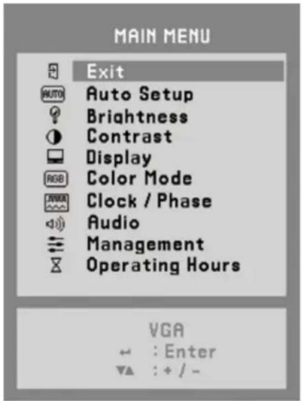
text_image
MAIN MENU Exit AUTO Auto Setup Brightness Contrast Display RGB Color Mode Clock / Phase Audio Management Operating Hours VGA ← : Enter ▼▲ : + / -Image 6-4 Main OSD menu
6.4.1 Exit
To exit the OSD menu.
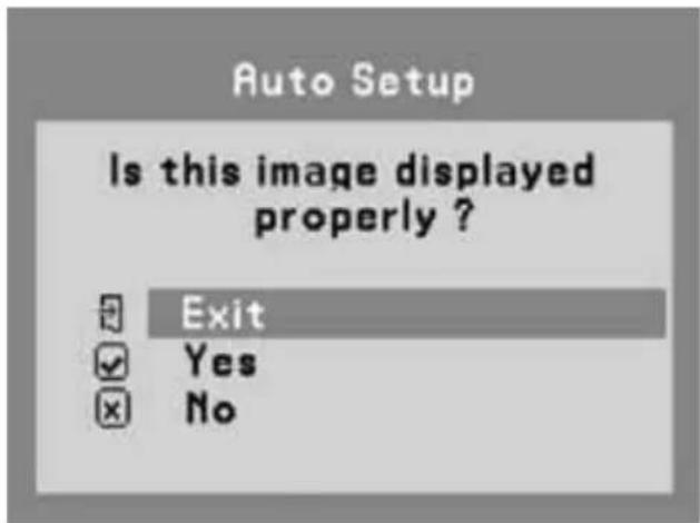
6.4.2 Auto Setup (Only Support Analog)
text_image
Auto Setup Is this image displayed properly ? Exit Yes NoImage 6-4-2 Auto Setup OSD menu
- Exit: To exit the auto setup of the OSD menu.
- Yes: Automatically adjust the analog settings of the image.
- No: Enter Clock/Phase OSD menu when NO is selected.
6.4.3 Brightness
This function allows the user to adjust the monitor's brightness setting manually.

text_image
Brightens -+100Image 6-4-3 Brightness OSD menu
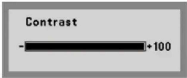
6.4.4 Contrast
This function allows the user to adjust the contrast setting of the monitor manually.
text_image
Contrast -+100Image 6-4-4 Contrast OSD menu
6.4.5 Display (Only Support Analog)
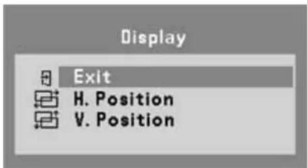
text_image
Display Exit H. Position V. PositionImage 6-4-5 Display OSD menu
- Exit: To exit the display of the OSD menu.
- H. Position: The function allows user manually adjust the image position horizontally on the screen
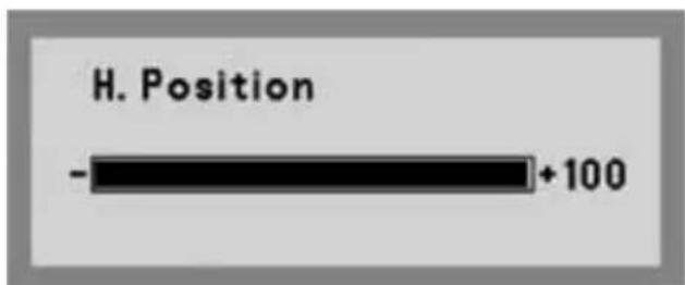
text_image
H. Position -+100Image 6-4-5-1 H. Position OSD menu
• V. Position: The function allows users manually adjust the image position vertically on the screen.

text_image
V. Position -+100Image 6-4-5-2 V. Position OSD menu
6.4.6 Color Mode
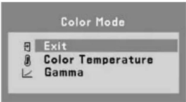
text_image
Color Mode Exit Color Temperature GammaImage 6-4-6 Color Mode OSD menu
- Exit: To exit the color mode of the OSD menu.
• Color Temperature: Allows users to select preset color temperature of the display setting. Preset color temperatures are 9300K, 6500K, 5400K & User adjustable color temperature.
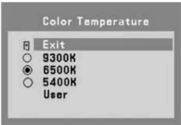
text_image
Color Temperature Exit 9300K 6500K 5400K UserImage 6-4-6-1 Color Temperature OSD menu
• User: User can adjust and set tones.
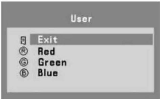
text_image
User Exit Red Green BlueImage 6-4-6-2 User OSD menu
- Red: Adjust red and equivalent colors at the range from 0 to 100. The greater the value is, the deeper the color is, and vice versa.
- Green: Adjust green and equivalent colors at the range from 0 to 100. The greater the value is, the deeper the color is, and vice versa.
-
Blue: Adjust blue and equivalent colors at the range from 0 to 100. The greater the value is, the deeper the color is, and vice versa User can adjust and set tones.
-
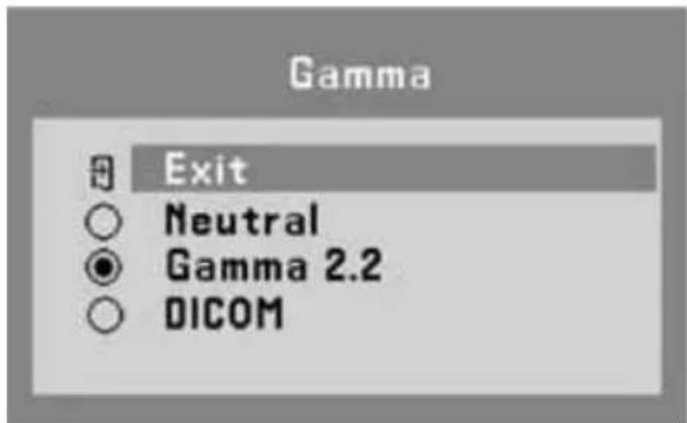
Gamma: Allows users to select preset gamma curve of the display setting. Preset gamma curve are Neutral & Gamma 2.2.
• DICOM: Allows users to select preset DICOM curve of the display setting.
text_image
Gamma Exit Neutral Gamma 2.2 DICOMImage 6-4-6-3 Gamma OSD menu
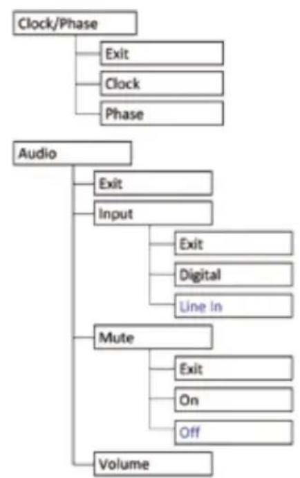
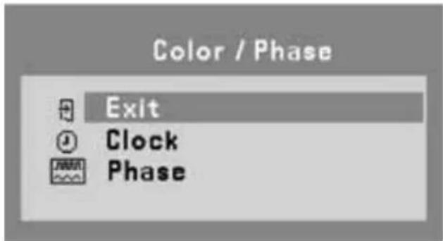
6.4.7 Clock/ Phase (Only Support Analog)
text_image
Color / Phase Exit Clock PhaseImage 6-4-7 Clock / Phase OSD menu
- Exit: To exit the Clock / Phase of the OSD menu.
- Clock: Allows users to adjust the clock of the display setting manually.
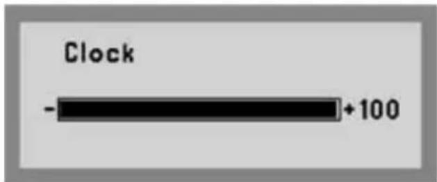
text_image
Clock - +100Image 6-4-7-1 Clock OSD menu
- Phase: Allows users to adjust the phase of the display setting manually.
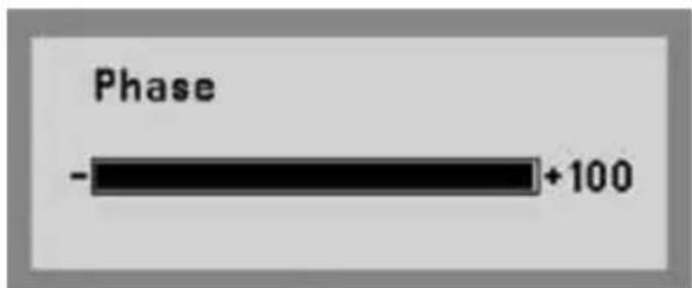
text_image
Phase -+100Image 6-4-7-2 Phase OSD menu
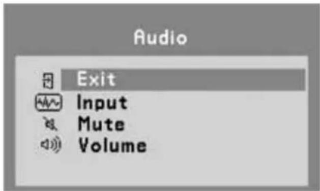
6.4.8 Audio
text_image
Audio Exit Input Mute VolumeImage 6-4-8 Audio OSD menu
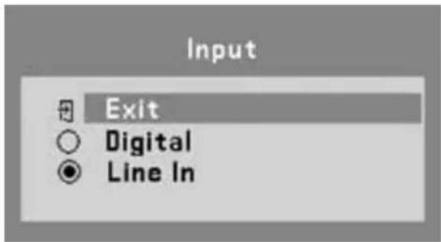
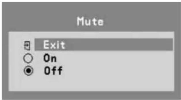
- Exit: To exit the Audio of the OSD menu.
- Input: Allows users to select the audio input source of the display setting. Digital & Line-In audio input source are available.
text_image
Input Exit ○ Digital ● Line InImage 6-4-8-1 Audio Input OSD menu
- Mute: Allows users to Mute(On) & Unmute(Off) the audio output of the display setting.
text_image
Mute Exit On OffImage 6-4-8-1 Audio Input OSD menu
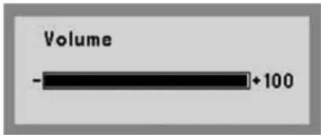
• Volume: Allows users to adjust the audio output of the display setting.
text_image
Volume -+100Image 6-4-8-3 Audio Volume OSD menu
6.4.9 Management
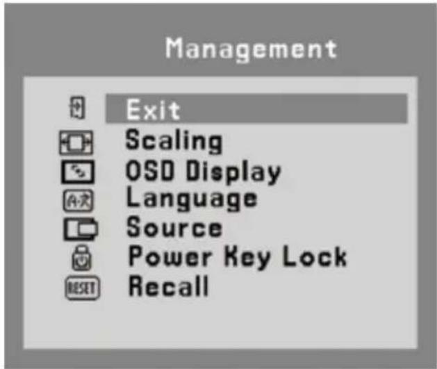
text_image
Management Exit Scaling OSD Display Language Source Power Key Lock RecallImage 6-4-9 Management OSD menu
- Exit: To exit the Audio of the OSD menu.
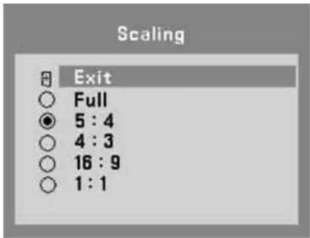
6.4.9.1 Scaling
Allows users to select preferred image scaling of the display setting
• Full screen: Expands the current image to the full size of the monitor.
- Aspect ratio (5:4, 4:3, 16:9): Expands the video image until its largest dimension fills the screen, while maintaining the aspect ratio of the image size. For example, when input timing is not equal to panel native resolution 1920x1080 (16:9 aspect ratio), the image may be displayed with black bars to fill the screen.
• 1 : 1: Display image as its original input image resolution.
text_image
OSD Display Exit OSD H. Position OSD V. PositionImage 6-4-9-2 OSD Display menu
- Exit: To exit the OSD Display of the OSD menu.
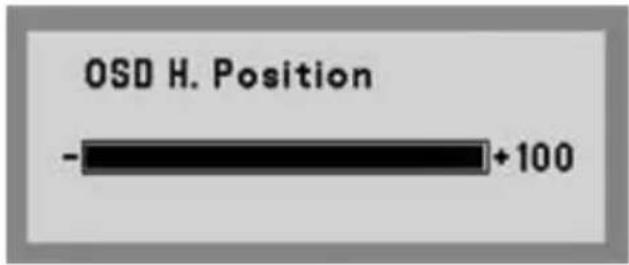
- OSD H. Position: Allows users to set OSD menu in horizontal position on the display.
text_image
OSD H. Position -+100Image 6-4-9-2a OSD Horizontal Position OSD menu
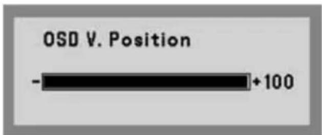
- OSD V. Position: Allows users to set OSD menu in vertical position on the display.
text_image
OSD V. Position -+100Image 6-4-9-2b OSD Vertical Position OSD menu
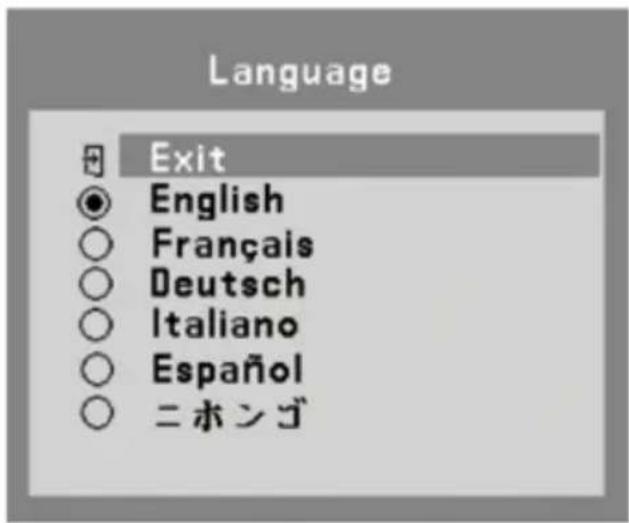
6.4.9.3 Language
- Exit: To exit the Language of the OSD menu.
- English, French, German, Italian, Spanish & Japanese OSD menu languages are available for users to select preferred languages.
text_image
Language Exit English Français Deutsch Italiano Español ニホンゴImage 6-4-9-3 Language OSD menu
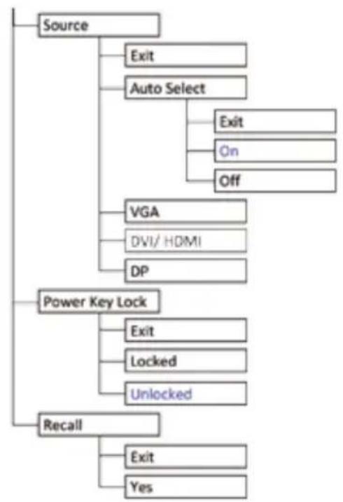
6.4.9.4 Source
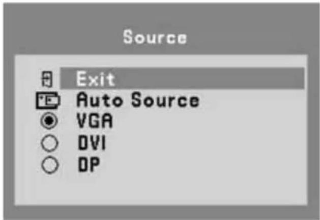
text_image
Source Exit Auto Source VGA DVI DPImage 6-4-9-4a Source OSD menu (RGP)
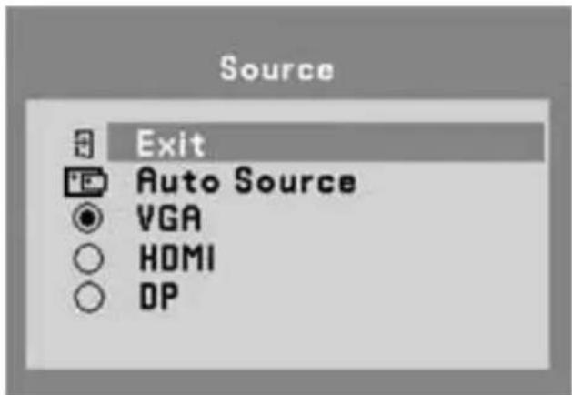
text_image
Source Exit Auto Source VGA HDMI DPImage 6-4-9-4b Source OSD menu (RGD)
- Exit: To exit the Source of the OSD menu.
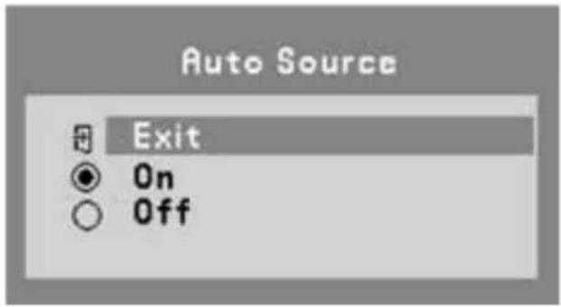
• Auto Source: Allows users to Enable or Disable the Auto Select function of the display setting.
text_image
Auto Source Exit On OffImage 6-4-9-4 Auto Source of the Source OSD menu
• VGA, DVI & Display Port (DP)/ HDMI sources are available for user to select preferred input source.
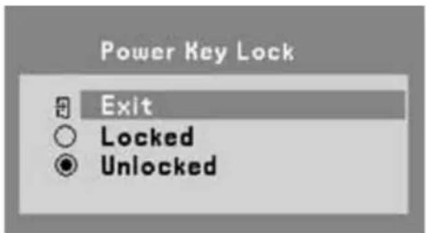
6.4.9.5 Power Key Lock
- Exit: To exit the Power Key Lock of the OSD menu.
- Locked: Allows users to Enable the DC power key function of the display setting.
- Unlocked: Allows users to Disable the DC power key function of the display setting.
text_image
Power Key Lock Exit Locked UnlockedImage 6-4-9-5 Power Key Lock OSD menu
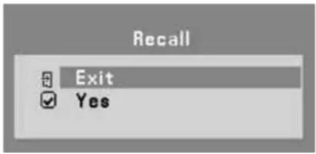
6.4.9.6 Recall
- Exit: To exit the Recall function of the OSD menu.
- Yes: Allows users to recall the display setting back to factory default setting.
text_image
Recall Exit YesImage 6-4-9-6 Recall OSD menu
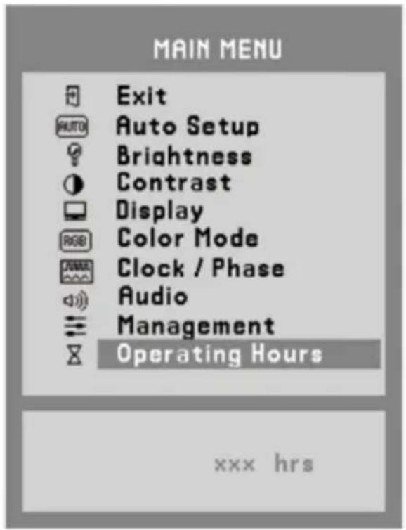
6.4.10 Operating Hours
- Keep records of the monitor operating hours.
text_image
MAIN MENU Exit AUTO Auto Setup Brightness Contrast Display RGB Color Mode Clock / Phase Audio Management Operating Hours xxx hrsImage 6-4-9-6 Recall OSD menu
Manufacturer
Consult your dealer for technical support.