GWK1 - Network Equipment Ganz - Free user manual and instructions
Find the device manual for free GWK1 Ganz in PDF.

User questions about GWK1 Ganz
0 question about this device. Answer the ones you know or ask your own.
Ask a new question about this device
Download the instructions for your Network Equipment in PDF format for free! Find your manual GWK1 - Ganz and take your electronic device back in hand. On this page are published all the documents necessary for the use of your device. GWK1 by Ganz.
USER MANUAL GWK1 Ganz

natural_image
White outdoor electronic device with a circular logo and black base (no visible text or symbols)QUICK START GUIDE

INDUSTRIAL OUTDOOR 802.11A/N WIRELESS ETHERNET
This manual serves the following GANZ Model Numbers:
GWK1
Thank you for purchasing the GWave wireless kit from GANZ. This quick start guide is designed to walk you through installation.
This guide applies to the following models:
GWK1: Industrial Point to Point Kit, FCC Version (Includes GWK1_AP and GWK1_CL)
An easy to read LED array displays unit operational status along with received signal strength ensuring optimal installation and operation. See Figure 2 on Page 2 for LED Indicator explanations.
See Figures 3 through 5 beginning on Page 3 for mounting instructions.
FIGURE 1 - INDUSTRIAL WIRELESS ETHERNET LINK

natural_image
White industrial water heater with a blue circular logo and 'GAVE' branding (no additional text or symbols visible)PORT 1 PORT 2
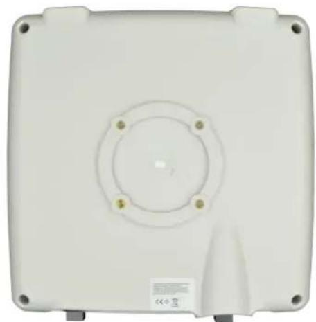
natural_image
White rectangular electronic device casing with circular vent and mounting holes (no text or symbols visible)BACKFRONT

natural_image
Front view of a medical device with two ports and a blue display screen (no visible text or symbols)BOTTOM
IMPORTANT: Only plug PoE power to Port 1. Connecting a PoE power source to the PSE Port (#2) will cause a major device malfunction and void the warranty.
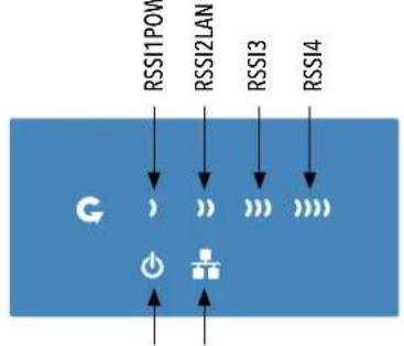
FIGURE 25- STATUS INDICATING LEDS
flowchart
graph TD
    A["RSI11POV"] --> B["G"]
    C["RSI2LAN"] --> B
    D["RSI3"] --> B
    E["RSI4"] --> B
    B --> F["Power Supply"]
    style B fill:#f9f,stroke:#333,stroke-width:2px
| LED VISUAL CUE INDICATION | ||
| POWER | SOLID GREEN Power is supplied to the unit | |
| OFF No power is supplied to the unit, or the unit is in reset. | ||
| LAN | SOLID GREEN LAN Connected | |
| OFF No Connectivity | ||
| RSSI1 SOLID RED Weak Connection | ||
| RSSI2 SOLID ORANGE Moderate Connection | ||
| RSSI3 SOLID GREEN | Solid Connection | |
| RSSI4 SOLID GREEN | Excellent Connection(Advisable to check Status Page to confirm RSSI is > -55) | |
SIGNAL STRENGTH:


WEAK SIGNAL EXCELLENT SIGNAL
FIGURE 3 - INSTALLATION INSTRUCTIONS
Step 1.
Unpack the mounting hardware from the box. Determine if this will be a pole or wall mount application. The included Mounting kit is designed to support poles up to 2 in (5.8 cm) in diameter. If surface or wall-mounting, additional hardware will be required.
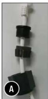
natural_image
Close-up of a white cable with black connectors, labeled 'A' in the corner (no other text or symbols visible)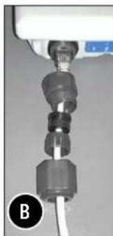
natural_image
Close-up of a mechanical connector with a white cable inserted, no visible text or symbols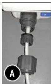
natural_image
Close-up of a medical or laboratory device with a metallic connector and labeled point A (no text or symbols on the device itself)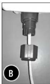
natural_image
Close-up of a mechanical component with a cable and a metallic connector (no visible text or symbols)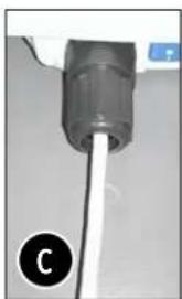
natural_image
Close-up of a cylindrical mechanical component with a white cable inserted, labeled 'C' in the corner (no text or symbols on the object itself)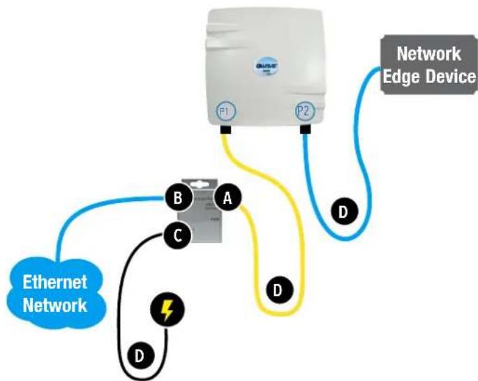
flowchart
graph TD
    A["Network Edge Device"] -->|P1| B["Ethernet Network"]
    A -->|P2| B
    A -->|D| C["Electrical Component A"]
    A -->|D| D["Electrical Component B"]
    A -->|D| E["Electrical Component C"]
    A -->|D| F["Electrical Component D"]
Step 2.
A. Route the RJ45 connectorized Ethernet cable through the weather tight gland connection as shown at left.
Note: The slit rubber washer allows a pre-terminated Ethernet cable to be used.
Once the cable has been routed through the weather connection as shown above, push the split rubber gasket into place and loosely screw the cap that goes over the rubber washer.
B. Snap the RJ-45 connector in place as shown
Step 3.
Slide the weather proof assembly over the cable so it can be screwed into the enclosure gland. Make sure the rubber sealing ring is in place as shown in step 3A.
Tighten the weather proof assembly into the enclosure and also tighten the cap that squeezes the rubber washer over the Ethernet cable as shown.
Step 4.
A. Connect one end of an RJ-45 Ethernet cable to the OUT port of the Power Injection Module (PIM) and the other end to LAN of the access point.
Maximum length of the RJ-45 CAT5 cable is 100 meters.*
B. Connect the RJ-45 Ethernet cable attached to the PIM to a network device, such as to a switch or to the PC you will use to configure the access point.
C. Connect the power adaptor to the main electrical supply and the power plug into the socket of the PIM.
PoE power input: Passive PoE (range 36 to 48 VDC). The GW1 can also be powered by a suitable IEEE 802.3af/at PSE device such as a PoE switch or injector.
D. A Drip Loop is recommended as additional precaution against moisture entering the Access Point housing.
* Up to 200mW radio. For higher power radio upgrade to higher rating power adapter.
FIGURE 4 - POLE MOUNT INSTRUCTIONS
Included Hardware

natural_image
Three metal mechanical components with bolt holes and bolts, shown from different angles (no text or symbols visible)Vertical Mount in -45° Position Vertical Mount in +45° Position

natural_image
Close-up of a white rectangular electronic device mounted on a vertical pole, with metal brackets and mounting bracket (no visible text or symbols)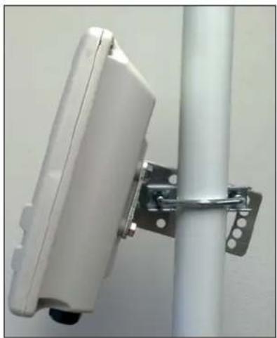
natural_image
Close-up of a white rectangular electronic device mounted on a vertical pole with metal hardware (no visible text or symbols)INSTALLATION REQUIREMENTS
Shielded outdoor CAT 5 or better should be used for all out of plant Ethernet connection and should be properly grounded through the PoE AC ground. Industrial grade shielded Ethernet cable is recommended to help prevent ESD damage commonly experienced with outdoor installations.
CONFIGURING GWAVE
- Connect an Ethernet cable from the port labelled as IN on the power Injection Module to either a laptop or a PC LAN port.
- Connect the second Ethernet cable from the OUT port on the Power Injection Module to the GWave LAN port.
- Apply 48 VDC to the Power Injection Module with the provided power supply. You should notice the green LED illuminate in the Power Injection Module and the power LED on the GWave unit.
- Set the IP address of the laptop being used to configure GWave to static and the subnet to 192.168.10.x/24 subnet.
- Point the Browser to 192.168.10.100 for the Access Point or 192.168.10.101 for the Client. These are the default addresses.
- A login prompt will pop up. Enter:
ID: admin
Password: admin
- Select the NETWORK » Interfaces tab, click on Edit in the LAN settings section to change the IP address of the device. and set the desired network settings.
- Hit Save & Apply
NOTE: This will be the network address for the GWave web server. It is not necessary to set to the same subnet as the operating network but it is recommended.
-
Select the NETWORK -> WIFI tab and set:
-
Wireless mode - Set to AP or Client
- Output RF power - if RSSI is greater than -40, it is recommended to reduce RF TX power at the connected remote node.
- Set SSID - if changing from the default setting
- Channel Spectrum Width - May want to reduce to 20M from the default 20/40M if the 5GHz spectrum is crowded or connections across the link are unstable.
- Wireless Security - if changing from default settings
- Hit Save & Apply
CONFIGURING MAC LOCK FOR POINT TO POINT LINKS
MAC-Filter replaces MAC-Lock on the first generation GWave hardware.
MAC-Filter is only available on devices operating as an AP. By default, it is disabled.
You can locate MAC-Filter tab by going to Networking -> WIFI -> Enable.

To enable and lock to a client radio, Click on the drop down menu and select "Allow Listed Only".
A new dialog box will appear. Click on the new bland dialog box and click on customer, enter the MAC address of the client radio you would like to MAC lock to and hit "Save & Apply".

UNDERSTANDING RSSI AND SIGNAL STRENGTH
The Received Signal Strength Indicator (RSSI) is intended to be used as an indicator of the quality of connection that exists between an Access Point and Client radio.
The RSSI value is determined by the Signal Strength.
Signal Strength is based on a number of factors, including the output power of the radios, antenna gain and the attenuation of the signal as it travels from the transmitter to the receiver.
Signal strength is expressed in dBm. dBm is a power ratio in decibels (dB) referenced to 1mW. Since most received signal levels are under 1mW, negative values are typically displayed. The more negative the number, the weaker the received signal.
The following can be used as a guideline to determine signal quality
| RSSI Signal Quality | |
| Less than -75 to -95 dBm No | Signal or intermittent operation |
| -75 dBm and greater Moderate Connection | |
| -65 dBm and greater Solid Connection | |
| -55 to Zero dBm | Excellent Connection |
RESET TO FACTORY DEFAULT
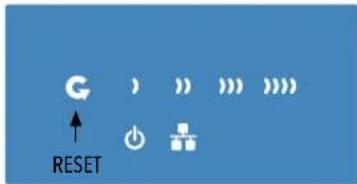
Press and hold the reset button for 4-30 Seconds to reset the radio back to factory defaults.
Note: A simple press of the reset button will restart the radio. Holding the reset button for longer than 30 seconds will not do anything.
Whenever the reset button is pressed, the power LED will go dark.
DEFAULT CONFIGURATIONS
IP Address of Web Server 192.168.10.100(GWK1_AP) 192.168.10.101 (GWK1_CL)
LAN Mode for Web Server Static Addressing
Web Server User ID admin
Web Server Password admin
SSID GWave-1
WPA Pre-shared Key 12345678
Channel-Frequency (AP) Auto
Channel Spectrum Width 20/40M
Long Range Parameters Enabled and defaulted to 1000m
NOTE: A Reset to defaults (performed on the ADMIN page or via the RESET button) will erase all user configurations.
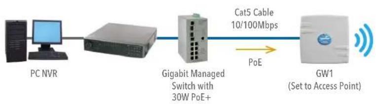
TYPICAL POINT-TO-POINT CONFIGURATION
flowchart
graph LR
    A["PC NVR"] --> B["Gigabit Managed Switch with 30W PoE+"]
    B --> C["Cat5 Cable 10/100Mbps"]
    C --> D["GW1 (Set to Access Point)"]
    B -->|PoE| D
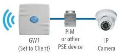
flowchart
graph LR
    A["GW1 (Set to Client)"] --> B["PIM or other PSE device"]
    B --> C["IP Camera"]
POINT-TO-POINT TOPOLOGY UTILIZING DUAL PORTS
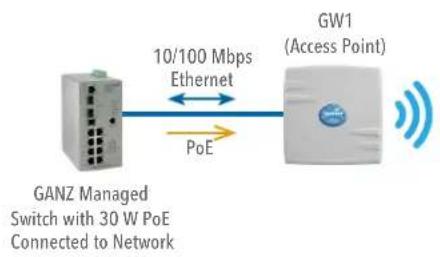
flowchart
graph LR
    A["GANZ Managed Switch with 30 W PoE Connected to Network"] -->|10/100 Mbps Ethernet| B["GW1 (Access Point)"]
    B -->|PoE| A
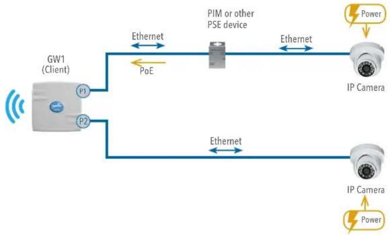
flowchart
graph LR
    A["GW1 (Client)"] -->|PoE| B["PIM or other PSE device"]
    A -->|PoE| C["IP Camera"]
    A -->|PoE| D["IP Camera"]
    B -->|Ethernet| E["Power"]
    C -->|Ethernet| F["Power"]
    D -->|Ethernet| G["Power"]
AGENCY COMPLIANCE
FCC
Changes or modifications not expressly approved by the party responsible for compliance could void the user's authority to operate the equipment. This device complies with Part 15 of the FCC Rules. Operation is subject to the following two conditions:
- This device may not cause harmful interference, and
- This device must accept any interference received, including interference that may cause undesired operation.
This equipment has been tested and found to comply with the limits for a Class A digital device, pursuant to part 15 of the FCC Rules. These limits are designed to provide reasonable protection against harmful interference when the equipment is operated in a commercial environment. This equipment generates, uses, and can radiate radio frequency energy and, if not installed and used in accordance with the instruction manual, may cause harmful interference to radio communications. Operations of this equipment in a residential area is likely to cause harmful interference in which case the user will be required to correct the interference at his own expense.
Industry Canada
This Class A digital apparatus complies with Canadian ICES-003. To reduce potential radio interference to other users, the antenna type and its gain should be so chosen that the equivalent isotropically radiated power (EIRP) is not more than that permitted for successful communication. This device complies with Industry Canada license-exempt RSS standard(s).
Operation is subject to the following two conditions:
• This device may not cause interference, and
- This device must accept any interference, including interference that may cause undesired operation of the device.
The antennas used for this transmitter must be installed to provide a separation distance of at least 2.52m from all persons and must not be located or operating in conjunction with any other antenna or transmitter.
CE marking on this product represents the product is in compliance with all directives that are applicable to it.
This equipment may be operated in the following countries:
Austria, Belgium, Denmark, Estonia, Finland, France, Germany, Greece, Hungary, Ireland, Italy, Latvia, Lithuania, Malta, Netherlands, Norway, Portugal, Romania, Czech Republic, Croatia, Slovakia, Slovenia, Sweden, UK
Installer Compliance Responsibility
Devices must be professionally installed and it is the professional installer's responsibility to make sure the device is operated within local country regulatory requirements.
RoHS/WEEE Compliance Statement
European Directive 2002/96/EC requires that the equipment bearing this symbol on the product and/or its packaging must not be disposed of with unsorted municipal waste. The symbol indicates that this product should be disposed of separately from regular household waste streams. It is your responsibility to dispose of this and other electric and electronic equipment via designated collection facilities appointed by the government or local authorities. Correct disposal and recycling will help prevent potential negative consequences to the environment and human health. For more detailed information about the disposal of your old equipment, please contact your local authorities, waste disposal service, or the shop where you purchased the product.
GANZ
Security Solutions
by
CBC AMERICAS Corp.
Corporate Headquarters, NY West Coast Mexico City
Tel: +1-800-422-6707 Tel: +1-877-407-9555 Tel: +52 55 5280 4660
ganzsecurity.com

Scan to view mobile catalog
CBC reserves the right to modify product specifications without prior notice and assumes no responsibility for errors in this publication. All products mentioned in this publication are acknowledged to be the property of their respective trademark owners.