HTL40 LINK - Television Sim2 - Free user manual and instructions
Find the device manual for free HTL40 LINK Sim2 in PDF.


| Product Type | 40-inch LCD Television |
| Brand | Sim2 |
| Model | HTL40 LINK |
| Display Technology | TFT-LCD with DigiOptic Image Processor |
| Screen Size (Diagonal) | 40 inches (16:9 native aspect ratio) |
| Resolution | 1366 x 768 pixels (HD) |
| Brightness | 600 cd/m² |
| Contrast Ratio | 1000:1 |
| Viewing Angle | ±85° (vertical and horizontal) |
| Response Time | 8 ms |
| Lamp Life | 60,000 hours (standard brightness) |
| Screen Dimensions (W x H x D) | 1106 x 656 x 103 mm |
| Screen Weight (approx.) | 35 kg |
| Power Supply | 120-240 VAC, 48-62 Hz |
| Power Consumption (Screen) | 200 W max |
| Power Consumption (Processor) | 30 W max |
| Video Inputs | 2 Composite, 2 S-Video, 4 Component/RGB, 2 Graphic RGB (DB15HD), 1 DVI-D, 1 HDMI |
| Audio Output | Optical S/PDIF (TOSLINK) |
| Control | Remote control, keypad on screen, RS232 serial port |
| Connectivity | Fibre optic cable (20 m, 3 cores) between processor and screen |
| Processor Dimensions (W x H x D) | 483 x 55 x 200 mm (19" rack compatible) |
| Processor Weight (approx.) | 2.5 kg |
| Safety Certifications | EN 60950, UL 60950 |
| Operating Temperature | 10 to 35 °C |
| Cleaning / Maintenance | Use soft cloth, mild soap for cover; screen with soft brush or dry cloth. No user-serviceable parts inside. |
Frequently Asked Questions - HTL40 LINK Sim2
User questions about HTL40 LINK Sim2
0 question about this device. Answer the ones you know or ask your own.
Ask a new question about this device
Download the instructions for your Television in PDF format for free! Find your manual HTL40 LINK - Sim2 and take your electronic device back in hand. On this page are published all the documents necessary for the use of your device. HTL40 LINK by Sim2.
USER MANUAL HTL40 LINK Sim2
natural_image
Illustration of a modern flat-screen TV with a teal cushion and black cover (no text or symbols visible)User and installation manual
HTL40 LINK

1 INTRODUCTION
Congratulations on your choice of the innovative SIM2 Grand Cinema HTL40 Link system!
natural_image
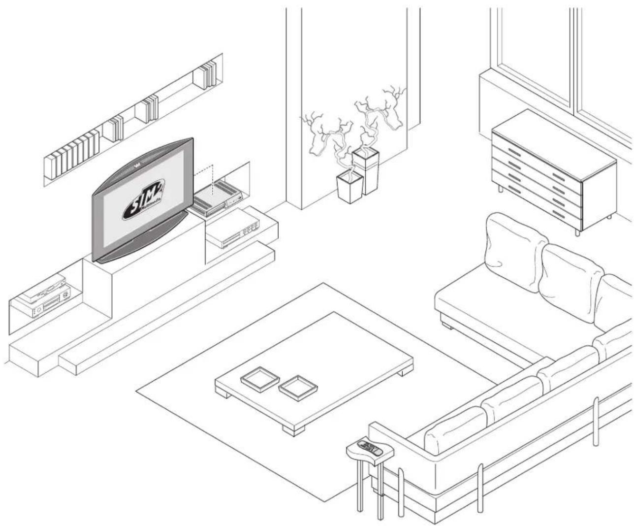
Line drawing of a modern living room interior with TV, sofa, and wall-mounted furniture (no text or symbols)The new HTL40 LINK flat screen offers the ideal combination between top TFT-LCD technology and an expert system for digital processing of video signals.
Your HTL40 LINK system is composed of two refined and elegant units. The 40" screen reflects the state of the art of TFT-LCD technology, with 1366x768 pixel resolution and the ability to display up to 16.7 million colours. The DigiOpticTM Image Processor video signal processing unit assures the acquisition of a very broad range of different video signals, while simultaneously providing the processing power needed to produce sharp, detailed pictures with bright natural colours.
The two units are interconnected by means of a single cable containing three fibre optic cores. The fibre optic cores allow the digital signal to be transmitted from the DigiOptic™ Image Processor to the screen and control signals to be transmitted in both directions.
Thanks to the flexibility and reduced diameter of the fibre optic cable, the two units can be sited in the room in a totally independent manner (distances of up to 500 metres), thereby ensuring that they will fit perfectly into the layout of your home theatre room.
A very broad range of different video signals can be connected to the DigiOptic™ Image Processor, which, since it is separate from the screen, can be placed anywhere in your room without detracting from the elegant styling and clean lines of the screen unit.
The large number of inputs available on the DigiOptic™ Image Processor (2 Composite Video inputs, 2 S-Video inputs, up to 4 Component or RGB inputs, 2 graphic RGB inputs, 1 DVI-D input, 1 HDMI™ input), ensures the system supports and processes a wide range of video signals from various sources: DVD players, VCRs, satellite and terrestrial receivers, computers, game consoles, video cameras, etc.
The signal processing capabilities of the Image Processor ensure optimum reproduction of a broad range of input signals, from in -terlaced video to high definition and graphics.
Conversion of interlaced video signals to progressive signals by means of prestigious DCDi™ technology produces fluid, natural images free of artifacts such as flicker and stairstepping on diago - nals.
Faithful reproduction of signals at higher resolutions (such as high definition video and graphics) occurs without loss of information or reduction of image sharpness thanks to the processor's high pixel rate signal acquisition capabilities.
In addition, the specific type of signal processing makes it possible to eliminate the swirl effects that can sometimes mar the performance of LCD screens when displaying moving images.
All image adjustments can be performed from the remote control with the aid of the On Screen Display; alternatively, the unit can be controlled by from a home automation system through the serial port.
Besides the usual checks, the Quality Control department also runs additional statistical tests before shipment. Therefore the packing may show signs of having been opened.
DCDi ^TM
byFAROUDJA

DIGIOPTIC™
by SIM2

HIGH DEFINITION MULTIMEDIA INTERFACE
DCDi is a registered trademark of Faroudja, a division of Genesis Microchip, Inc. DigiOptic™ is a registered trademark of SIM2.
HDMI, the HDMI logo and the expression High-Definition Multimedia Interface are trade marks or registered marks of HDMI licensing LLC
2 IMPORTANT SAFETY INSTRUCTIONS
CAUTION!
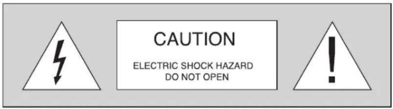
To reduce the risk of electric shock, disconnect the power supply cable on the rear panel before removing the cover of the screen.
For technical assistance refer to trained personnel authorised by the manufacturer.
This symbol indicates the possible electric shock hazard associated with uninsulated live components inside the unit.

This symbol indicates the presence of important instructions regarding use and maintenance of the product.
The HTL40 LINK system consists of two parts connected by a fibre optic cable: the DigiOptic™ Image Processor and the screen. In this manual references to the DigiOptic™ Image Processor unit and to the screen unit refer to the two units that make up the system.
LAMP WARNING
If the lamp should suddenly burst with a loud bang, air the room thoroughly before using it. Do not change the lamp: seek qualified technical assistance from your nearest Dealer.
CLASS 1 LASER PRODUCT
This product complies with FDA radiation performance standards, 21 see chapter 1 subchapter j.
This product complies with European standard EN 60825.
This product is classified as a class 1 laser product and it does not emit hazardous levels of radiation assuming the safety protections are in place.
Caution! invisible laser beam when the product is open.
Avoid direct exposure to the laser beam.
To avoid exposure to visible or invisible laser radiation do not open product cover panels and do not touch internal parts.
Read all chapters of this manual carefully before switching on the screen. This manual provides basic instructions for using the HTL40 LINK system. Installation, preliminary adjustments and procedures that necessitate opening the units and touching electrical components must be carried out by authorised, trained technicians. To ensure safe and long term reliability use exclusively the power cables supplied by the manufacturer. Observe all warnings and cautions.
PARTS LIST
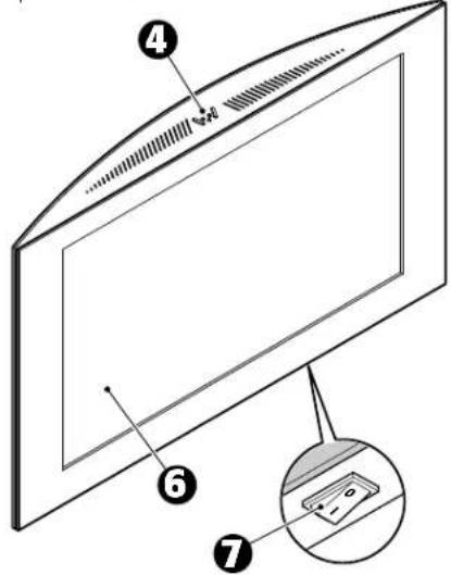
SCREEN
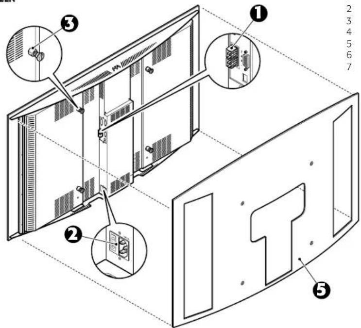
1 Fibre optic cable connectors.
2 Fused power socket.
3 Threaded bushes.
4 Keypad
5 Curved rear panel.
6 Screen
7 Mains power switch
。
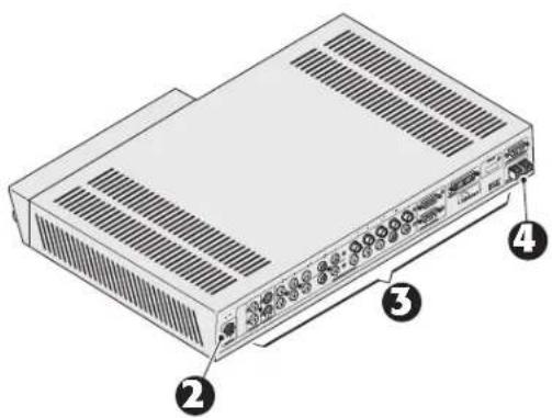
DIGIOPTIC™ IMAGE PROCESSOR
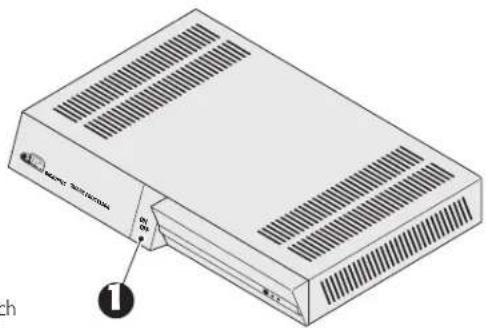
1 ON/OFF power switch
2 Mains power supply
3 Motorised screen outputs
4 Inputs
5 Fibre optic cable connectors
- Read this manual carefully and keep it in a safe place for future consultation.
This manual contains important information on how to install and use this equipment correctly. Before using the equipment, read the safety prescriptions and instructions carefully. Keep the manual for future consultation.
- Do not touch internal parts of the units.
The units contain electrical parts carrying high voltages and operating at high temperatures. Do not remove the cover from the units, refer to qualified service personnel for all repair and maintenance requirements. The warranty will be automatically invalidated if the cover is removed from the units.
• Power supply disconnect device.
The device for disconnecting the units from the mains power supply is constituted by the power cable plug. Ensure that the power cable plugs and the electrical mains socket outlets are easily accessible during installation operations. To disconnect the units from the electric power supply, pull the plug to remove it from the socket outlet. Do not pull the power cable.
- Connect the unit only to the type of power supply indicated.
Connect the units to a mains electrical supply with rated voltage of between 120-240 Vac, 50/60 Hz and equipped with a protective earth connection. If you are unsure of the type of mains power supply in your home, consult a qualified electrician. Ensure that the power draw of the units is commensurate with the rating of the electrical socket outlets and any extension cables that are used. For the DigiOptic™ Image Processor use exclusively the power supply unit provided or an alternative power supply unit expressly approved by SIM2.
- Connection of the units to the mains power supply.
Make the connection as shown in Fig.1. Before connecting the panel to the electrical mains supply, follow the setup instructions carefully.
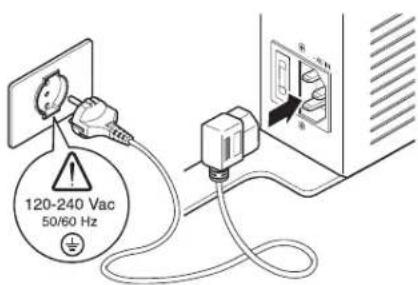
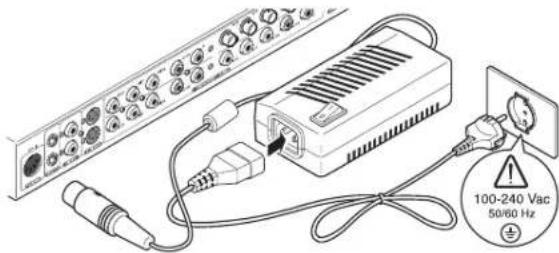
Fig.2
- Changing the fuses.
Before changing the fuse disconnect the unit from the mains power supply.
The fuse compartment is next to the mains power connector (Fig. 3). Remove fuse carrier (2) with the aid of a flat blade screwdriver, then change fuse (3). Insert a new spare fuse (4). Use only T 3.15A H fuses.
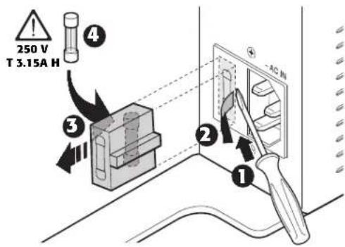
Fig.3
- Be careful with cables.
Position the power supply cables so that they do not constitute an obstruction.
Keep cables out of the reach of small children.
Install the units as close as possible to the wall electrical socket outlet. Do not tread on the power cables, make sure that they are not tangled or pulled; do not expose the power cables to heat sources; make sure that the power cables do not become knotted or kinked. If the power cables become damaged, stop using the system and request the assistance of an authorised technician.
Fig.1 7
- Disconnect the unit from the mains power supply in the event of electrical storms and when not in use.
To avoid damage that could be caused by lightning striking in the vicinity of your home, disconnect the units in the event of electrical storms or when the system will remain unused for prolonged periods.
- Avoid contact with liquids and exposure to humidity.
Do not use the units near water (sinks, tanks, etc.); do not place objects containing liquids on top of or near the units and do not expose then to rain, humidity, dripping water or spray; do not use water or liquid detergents to clean the units.
- Prevent the units from overheating.
Do not obstruct ventilation openings. Do not place the units near heat sources such as heaters, radiators or other devices that generate heat (including amplifiers). Do not position the units in confined, poorly ventilated places (bookcase, shelves, etc.).
- Never look directly at the projection lamp.
Never look directly at the lamp through the ventilation opening when the unit is switched on. Risk of eyesight impairment. Ensure also that children do not look directly at the lamp.
- Position the unit on a stable surface.
The screen must be positioned on a suitable stable surface or be installed using a bracket for fixed ceiling or wall installation. Never use the screen by resting it on either of its sides or on the rear panel.
- Do not insert objects through the openings in the unit.
Make sure that no objects are inserted inside the units. If this should occur, disconnect the unit from the power supply immediately and call an authorised technician.
3 UNPACKING
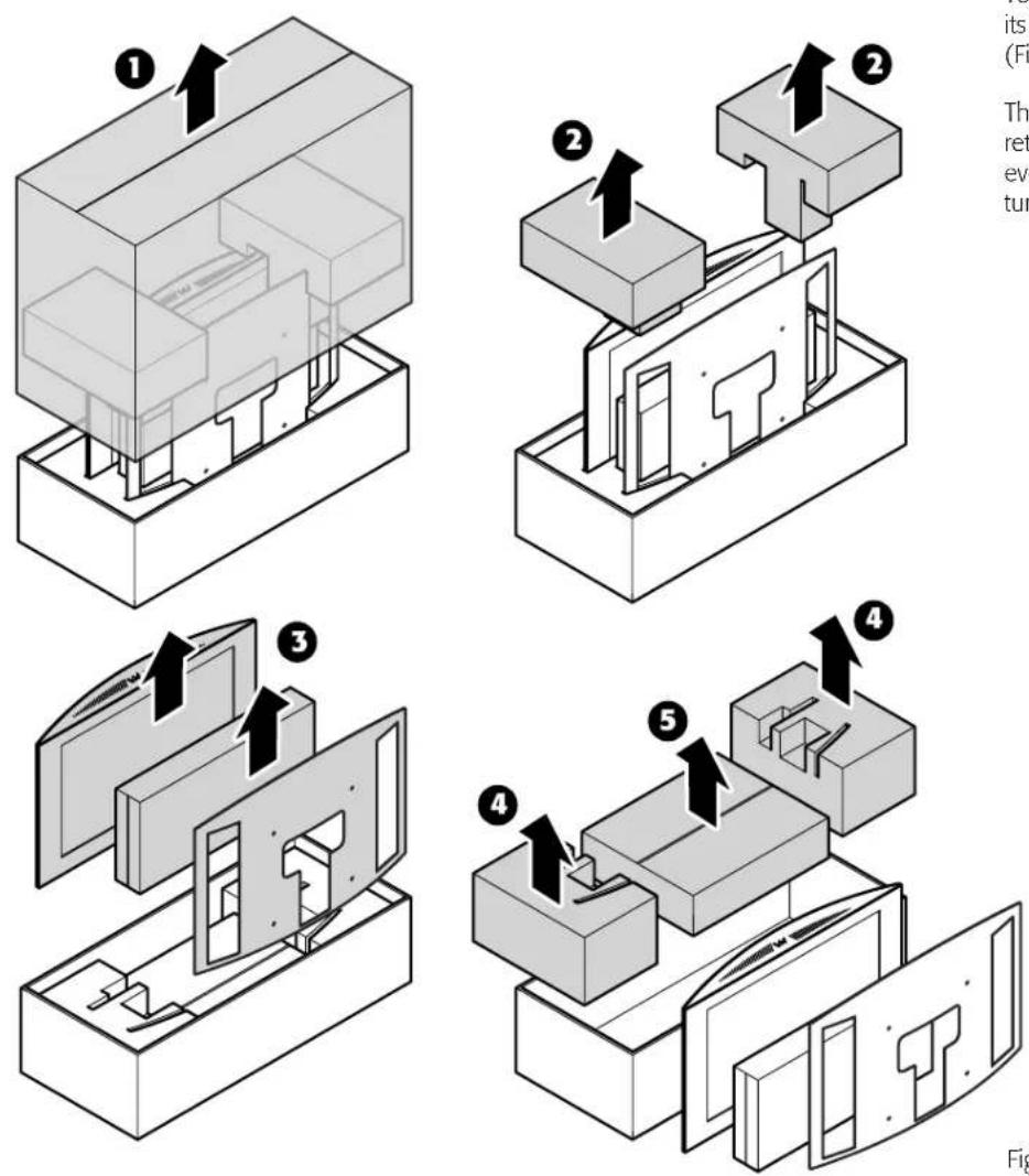
To remove the HTL40 LINK system from its carton follow the figures on the left (Fig. 4).
The carton and packaging should be retained for future use and in the unlikely event that your system needs to be returned for repair.
Fig.4
PACK CONTENTS
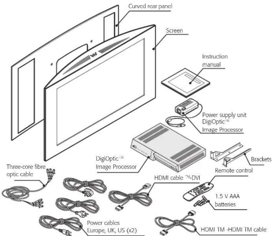
Fig.5
The packing carton contains the following parts:
- Screen
- Curved rear panel
- DigiOptic™ Image Processor
- remote control
- four 1.5V AAA batteries (for remote control)
- DigiOptic™ Image Processor power supply unit
- three power cables (EU, UK, USA) for the screen
- three power cables (EU, UK, USA) for the DigiOptic™ Image Processor
-
cable with three fibre optic cores
-
one HDMI™-HDMI™ cable
- one HDMI™-DVI cable
- two brackets for fixing the DigiOptic™ Image Processor to the rack
- user manual.
If any accessories are missing, contact your Dealer as soon as possible.
4 INSTALLATION
POSITIONING THE TWO UNITS
The HTL40 LINK system consists of two separate units (the DigiOptic™ Image Processor and the screen), each of which is equipped with a power cable; the two units are interconnected by a 20 m fibre optic cable.
Positioning the DigiOptic™ Image Processor
The ideal location for the DigiOptic™ Image Processor is on a cabinet shelf or on a rack (dimensions are compatible with a standard 19" rack). Make sure that the support surface is stable and that the unit has sufficient space around it for ventilation purposes (at least 3 cm).
The unit is connected to the mains via an external power supply unit with an output of +7 Vdc; the unit's main power switch is on the power supply unit. Connect the power supply unit output cable to the POWER socket located on the rear panel (Fig. 2).
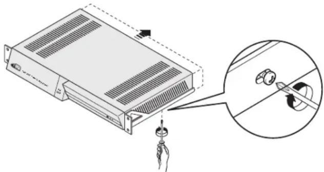
Use exclusively the power supply unit provided with the system or an alternative power supply unit expressly approved by SIM2. For rack mounting of the DigiOptic™ Image Processor use the screws and LH / RH supports supplied with the product. Undo the screws fixing the cover to the base of the DigiOptic™, position the LH and RH supports and secure them to the unit with the screws supplied. Use the supplied screws to secure the unit to the rack (Fig.6).
natural_image
Diagram of a server rack with a hand holding a tool, showing a close-up of its internal components (no text or symbols present)Fig.6
Positioning the screen unit
Some minor assembly steps must be carried out on the screen unit before it can be positioned correctly. The display can be installed on a wall, using the specific VESA rails and the supplied screws, or placed on a table using the supporting base (optional - For further requirements or information concerning the support base contact
your nearest SIM2 dealer).
The following section describes the operations to be performed for the various installation configurations.
Caution! All the operations described below must be executed exclusively with the mains power cable unplugged from the mains socket outlet.
Caution! Do not place the wooden rear panel against ir - regular surfaces or surfaces that anyway could damage the panel. Protect the rear panel from scoring or other damage. Do not scratch the rear panel by means of rubbing against other surfaces or score it through contact with sharp objects. Do not place any objects on the rear panel and avoid laying it flat if possible.
WALL MOUNTING
Caution! Wall mounting of the LCD screen calls for special skills and must be carried out exclusively by authorised, trained technicians. Because of the weight of the screen (approx. 345 N, 35 kg) wall mounting operations should be carried out with at least two people. Sim2 Multimedia declines all liability for possible injury to persons or damage to property deriving from incorrect installation of the screen.
Fixing of the display to the wall is performed by means of an attach ment in compliance with VESA FDMITM standards (VESA Flat Display Mounting Interface Standard). The fixing system is not supplied with the HTL40 LINK system. VESA fixing systems are readily available commercially. Before purchasing a fixing system ensure it is approved to hold a weight in excess of 40 kg. In particular, we recommend checking that the wall to which the screen is to be fixed is able to support a weight of at least five times the total weight of the unit composed of the mounting interface and the display. Otherwise the structure must be reinforced before installing the unit. Fix the HTL40 LINK screen to the VESA interface system by means of 4 screws (M8), as shown in (Fig.7).
Caution!
Follow the instructions supplied with the VESA interface system carefully. Improper installation of the unit can result in serious personal injury and major damage to the HTL40 LINK panel and surrounding objects.
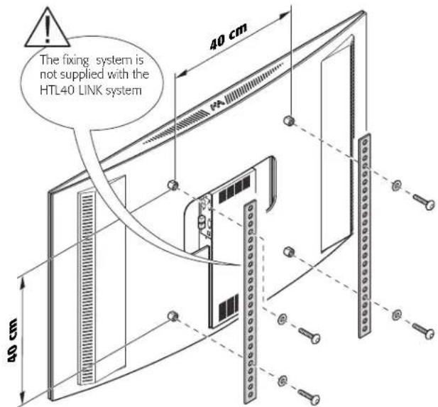
Fig.7
Make sure the components listed below are readily available:
- TFT-LCD flat screen
- curved rear panel.
- the fixing screws.
- spacers for installation with VESA interface
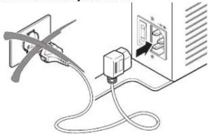
With the panel supported in a vertical position, insert the mains power cable connector into the relevant socket on the rear of the LCD panel (Fig.8).
Caution! Do not supply power to the panel by plugging the power cable into the mains socket outlet until you have finished the installation procedure.
natural_image
Line drawing of a cable being inserted into an electrical outlet (no text or symbols)Fig.8
Remove the protective caps from the LCD panel connectors making a mental note of the number markings and then insert the fibre optic cable in accordance with the diagram in Fig.9.
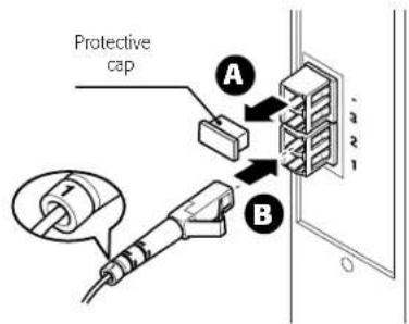
Fig.9
Position the styled rear panel at the back of the display and line up the four holes with the bushes already fitted (Fig.10A).
Caution! When fitting the rear panel make sure it is per - fectly parallel to the screen. Use caution to ensure that the central opening in the rear panel is correctly aligned with the corresponding metal parts located in the panel rear: the use of excessive force when fitting the rear panel could damage the edges of its internal openings.
In the case of wall mounting, screw the spacers into the holes in the rear panel (Fig.10B).
Caution! Take particular care when inserting the spacers in the relevant holes. Excessively forceful insertion could cause damage to the edges of the holes in the curved rear panel.
Screwing the spacers into the holes makes it possible to increase the distance between rear panel and the wall to which the rear panel is secured, this making it possible to position the display freely. Finally, secure the rear panel to your VESA interface (not included).
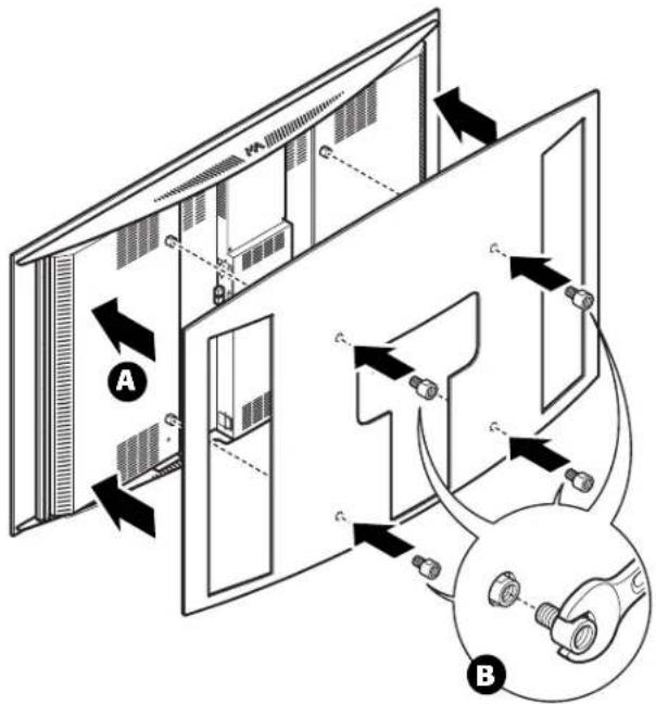
Fig.10
TABLETOP INSTALLATION WITH SUPPORT BASE (OPTIONAL)
For tabletop installation of the unit you will need the tabletop support, which is sold separately from the HTL40 LINK system.
For more details on the tabletop support and the various models available contact your nearest dealer.
Fit the screen into the tabletop support, aligning the slots on the bottom of the screen unit with the vertical tabs on the support (Fig.11A). Secure the support to the screen by screwing in the two screws in the rear (Fig.11B).
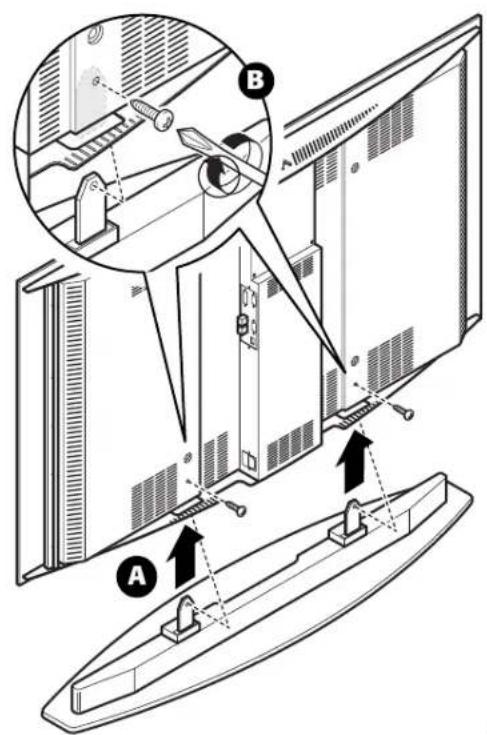
Fig.11
With the panel in its vertical position, insert the power cable plug into the socket on the LCD panel (Fig.8).
Caution! Do not supply power to the panel by plugging the power cable into the mains socket outlet until you have finished the installation procedure.
Remove the protective caps from the LCD panel connectors making a mental note of the number markings and then insert the fibre optic cable in accordance with the diagram in Fig.9.
Position the curved rear panel at the back of the display and line up the four holes with the bushes (Fig.12A) fixing the parts together with the flathead screws (Fig.12B).
Caution! When fitting the rear panel make sure it is always kept parallel to the screen. Ensure that the central opening of the curved rear panel is well aligned with the corresponding metal parts located in the rear of the flat panel screen: excessively forceful insertion of the curved rear panel could damage the edges of its internal openings.
Caution! Take particular care when inserting the flathead screws in their holes. Excessively forceful insertion could cause damage to the edges of the holes in the curved rear panel.
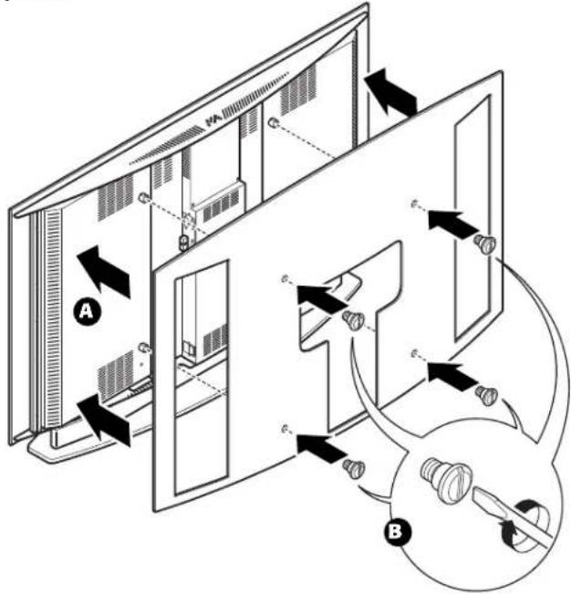
Fig.12
CONNECTING THE TWO UNITS
The system can be fully controlled using the supplied IR (infrared) remote control handset.
There is a single remote control for both the DigiOptic™ Image Processor and the screen; the remote control can be directed towards either unit since they are both equipped with an IR sensor.
The connection between the two units is made with a single cable containing three fibre optic cores each terminating in an LC connector.
The standard cable length of 20 m will be sufficient for most installation requirements.
During installation of the fibre optic cable:
- The individual optical cables are delicate: always handle the main cable without touching the individual optical cables (Fig.13). Never pull the individual optical cables or connectors; if necessary, you may pull the main three-core cable.
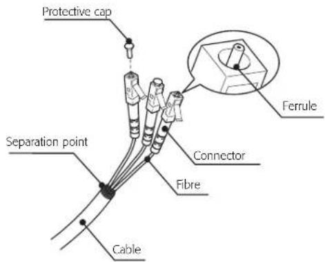
Fig.13
- Only remove the cap protecting the connector ferrule immediately before inserting the connector; if the ferrule is allowed to come into contact with foreign material it may be damaged, making the connector unusable.
- Take particular care when inserting fibre optic connectors in their respective sockets on the rear panel of the DigiOptic™ Image Processor and the rear panel of the screen.
- Make sure that the single optical cables are not switched: the numbers on the cables must match the numbers on the connectors.
- Check that the connectors are correctly inserted.
• Make sure that the cable does not constitute an obstacle for persons moving around the room.
• Take care not to create knots in the cable; the minimum radius of bends in the cable is 2 cm. - Prevent the cable from pulling and mechanical stress: this could cause the connectors to be pulled out and damaged.
After removing the protective caps from the fibre optic cable connectors and the panel connectors, insert the fibre optic connectors carefully, matching the numbers shown on each element (Fig.14). Be very carefully when handling optical fibres cable and connectors.
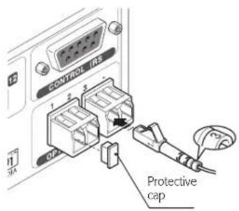
Fig.14
Avoid exposing the panel to direct light sources.
As far as possible it is also advisable to avoid placing light coloured furniture or other objects with highly reflective surfaces in the immediate proximity of the screen.
CONNECTING THE VIDEO SOURCES
Connect the cables from the video sources, the serial cable from the external control unit and the optical fibre cables connection to the rear panel of the DigiOptic™ Image Processor.
To obtain the best performance from the HTL40 LINK system, connect the various signal sources using good quality cables designed for video applications (rated impedance 75 [IMG]).
Ensure that:
- the cables are routed in such a way that they do not present an obstruction to people moving around the room;
- the connectors are inserted carefully to avoid damaging the pins;
• the cables are not twisted or crushed; - when disconnecting the cables the connectors are not violently pulled out of the connectors on the various units.
Video sources (television receivers, VCRs, DVD players, etc.) often feature several outputs. To obtain the best performance from your system, carefully choose which output to use. Generally, the type of signal offering the best picture quality is DVI-D, followed by RGB, Components, S-Video and Composite Video, in that order.
However, the HTL40 LINK system is equipped with an excellent Video Decoder and Deinterlacer and therefore even inferior quality signals will produce high quality results.

Table 1 shows the types of signals usually available for the most common types of video sources and the corresponding input connectors to use on the DigiOptic™ Image Processor.
Table 1
| DigiOpticTMImage Processor Connector | Video signal source connector | ||
| Y (green) | Y | Y | Y |
| Cr (red) | P_R | R-Y | V |
| Cb (blue) | P_B | B-Y U | |
VIDEO 1 2 3
These inputs should be connected to a Composite Video signal (CVBS) by means of a cable with an RCA connector.
The connector on the source is usually yellow and is frequently labelled VIDEO.
Although other types of signals are preferable (since they allow better picture quality), this is still the most common type of output, and nearly all television receivers, videorecorders, DVD players, video cameras, etc., are equipped with CVBS outputs.
S-VIDEO 4 5
These inputs should be connected to an S-Video signal by means of a cable with a 4-pin mini-DIN type connector.
The corresponding output on the source can be identified by the wording S-VIDEO or Y/C.
Almost as widespread as Composite Video, S-VIDEO is preferable because it offers a clearer and sharper picture.
COMPONENT / RGBS 6789
These inputs are composed of three sets of 5 RCA connectors (5,6,7) and a set of 5 BNC connectors (8).
Each set of connectors is suitable for RGB and Component signals.
RGB signals can have the following synchronisations: composite sync on the green signal (RGsB), H+V Composite Sync, or separate H/V Sync.
Connect the R, G, B outputs of the source to the respective R, G, B inputs of the DigiOptic™ Image Processor (taking care not to invert the positions) and any synchronisation signals to the HV input or the
H and V inputs. When connecting the three sets of RCA connectors use the colours as a guide: connector R is red, G is green, B is blue, H/HV is white and V is black.
By using a suitable SCART to RCA (or BNC) connector adapter cable, an RGB video signal from a source equipped with an SCART connector can be connected to this input.
Component signals are connected to inputs Y, Cr and Cb, taking care to observe the correspondence with the outputs on the source. Since the latter can be labelled in various ways, refer to Table 1 to establish the correspondence between the various signals. The connector colours can also be of help, as shown in the table.
Input 5 can receive RGB and YCrCb signals not higher than 32 kHz. In effect, to provide high picture quality even with relatively inaccurate sources, the input signal is processed by specific circuits in the DigiOptic™ Image Processor.
The video signals that can be connected to inputs 6-7-8 can have horizontal scanning frequencies of 15 kHz (standard video resolution), 32 kHz, or higher (progressive scanning video, high definition video).
Some sources provide the facility to choose between a progressive signal or an interlaced signal. Although in general a progressive signal is higher quality than an interlaced signal, it is often preferable to perform the deinterlacing operation on the HTL40 LINK system rather than on the source because the HTL40 LINK system is equipped with Faroudja's sophisticated directional correlation deinterlacing technology (DCDi™).
Progressive signals usually provide better quality than interlaced signals, but if the source features both progressive and deinter laced signal outputs it is good practice to compare the quality of the pictures reproduced by the HTL40 LINK system in the two cases: deinterlacing performed by the HTL40 LINK system (thanks to Faroudja DCDi™ technology) is often more effective than that performed at the source (typically a DVD player).
GRAPHICS RGB 10 11
This input should be connected to an RGB-type video or graphic signal using a cable with a DB15HD type connector.
The signal source device (typically a personal computer or game console) must be able to provide separate H/V synchronisation or composite H+V synchronisation.
The video or graphic signals that can be connected to this input can have horizontal scan frequencies (H-sync) of between 32 and 80 kHz and a vertical frequency (V-sync) of between 48 and 100 Hz. Image resolution can vary between 640x480 and 1600x1200 pixels (VGA, SVGA, XGA, SXGA, UXGA).
DVI-D 12
This input provides the facility to exploit the quality of the digital image to its best advantage. If the source is equipped with a DVI-D, YCrCb or RGB output, connect it to this input to get the most out of your HTL40 LINK system.
HDMI
This input provides the facility to integrate the excellent quality of a digital image with a multichannel audio signal.
In fact the High Definition Multimedia Interface (HDMI ^™ ) combines the uncompressed high definition video signal with a multi-channel audio signal.
In addition, the interface enables control data to be exchanged between the video source and the HT system in order to optimise the displayed picture.
The HDMI ^™ input makes it possible to connect to video sources that use the High-Bandwidth Digital Content Protection protocol (HDCP) to protect their contents. This is possible because the HDCP protocol forms part of the definition of HDMI ^™ technology.
Once the video source has been connected to the HDMI™-input, the internal processing performed by the DigiOptic™ Image Processor separates the video and audio information. The audio information is made available on a digital output with a female TOSLINK connector in compliance with the S/PDIF standard.
CONTROL (RS232)
The system can be controlled via a personal computer or home automation systems by means of the serial port: simply connect this input via a serial cable from an RS232 serial port. On request, SIM2 will send you a document containing the serial port settings and a list of the main commands.
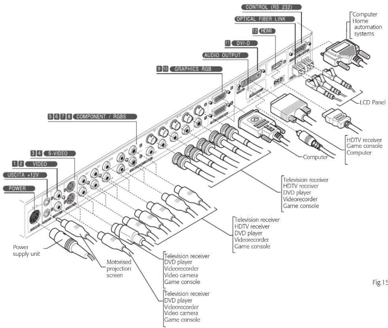
5 SWITCHING ON AND OFF
The HTL40 LINK system consists of the Screen and the DigiOptic™ Image Processor (which is also the system control centre). The DigiOptical Image Processor sends commands to the screen and receives operating status information from the screen and function commands from the user.
The system can be controlled from either the remote control (via the infrared sensors on the DigiOptic™ Image Processor and on the screen) or the keypad located at the top of the LCD panel. However, the power supply to the two units is separate.
After interconnecting the units via the fibre optic cable (see CONNECTING THE TWO UNITS") they must both be connected to the electrical mains supply.
Now proceed with the power-up procedure described below.
Power-up sequence
1) Set the LCD screen power switch at the bottom of the rear panel to "I" (ON) (Fig.16A).
2) Set the DigiOptic™ Image Processor power switch on the external power supply unit to "I" (ON) (Fig.15B).
Caution! In this phase make sure the DigiOptic™ Image Processor ON/OFF button (Fig. 16C) is in the OFF position: in this condition the indicator LEDs on the front panel of the DigiOptical™ Image Processor should not be lit.
3) Power-up of the DigiOptic™ Image Processor (Fig.16C).
4) Wait for a few seconds.
5) Power-up the system by pressing one of the number buttons 0...9 on the remote control (Fig.16D).
Caution! The power-up sequence described at points 1, 2, 3, 4 and 5 must be observed in full; otherwise the system will not initialise properly and the power-up sequence must be repeated in accordance with the proper procedure.
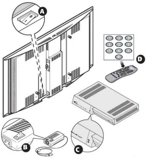
(Fig.16)
After a few seconds (system initialisation interval), the DigiOptical™ Image Processor and the Screen assume stand-by mode.
System status information is provided by two LEDs (green and blue) on the front panel of the DigiOptical™ Image Processor and on the rear of the screen.
Significant status signals are illustrated in Table 2.
Table 2
| Status | DigiOpticTM Image Processor | Projector | |
| Green LED | Blue LED Blue LED | ||
| Off | ○ | ○ | ○ |
| Initialisation | ● | ● | ○ |
| Standby | ○ | ● | ● |
| On | ● | ○ | ○ |
| Optical link not active | ● | ☀ | ● |
| Caution | ○ | - | |
| Error | ○ | - | |
If the "No optical link" or "Error" signals are active the system will not function; if the "Warning" signal is active the system will operate but it may be unable to read certain input signals correctly.
SWITCHING ON AND OFF FROM STAND BY
Switching on the system (Fig.17):
• from the remote control (keys 0-9)
• from the screen keypad (keys ▲ and ▼).
Typically, the picture will appear after 15-20 seconds.
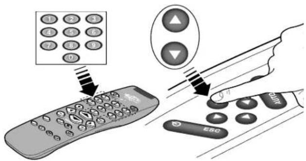
Fig.17
Pressing a key from 1-9 on the remote control selects the corresponding input; pressing 0 selects the input that was active at the time the system was last switched off.
Switching off the system (Fig.18):
• from the remote control (key ⏻)
• from the screen keypad (key ⏻)
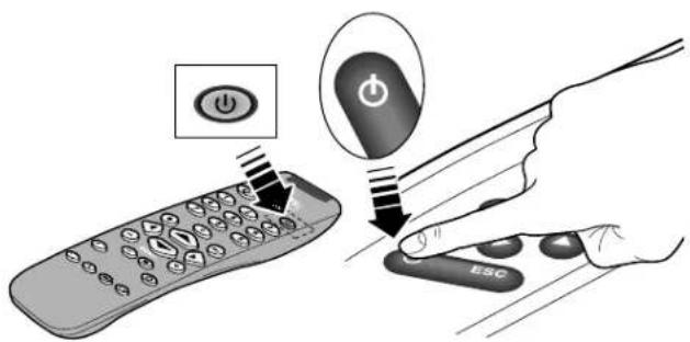
Fig.18
If you wish to power off the two units completely, wait at least one minute in stand-by to allow the units to cool before setting the mains power switches to the "O" position or unplugging the power supply cables.
If power is disconnected from the Screen unit (e.g. setting the mains power switch to the "O" position or inadvertently unplugging the power cable), to restart the HTL40 LINK system also power-off the DigiOptic™ Image Processor unit and repeat the power-up sequence described at points 1 and 5.
If the fibre optic link between the two units is interrupted (e.g. by removing one or more cables) to restore normal system operation switch off the two units by means of the mains power switches, restore the fibre optic connections, and then repeat power-up mode steps 1 and 5.
6 KEYPAD
The keypad on the top of the screen features eight keys providing the facility for complete control of the unit even without the remote control.
(
Sets screen to stand-by.
Esc
Displays information concerning the displayed video/graphic signal and the operating status of the system. Closes the On Screen Display.
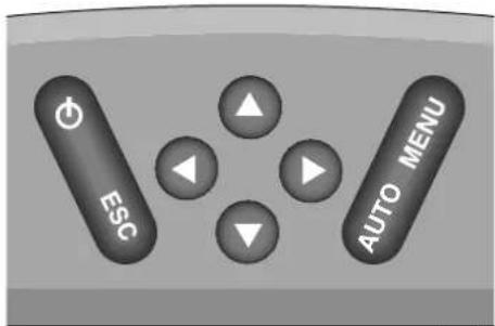
Fig. 19
Menu
Activates the On Screen Display menus and allows navigation though the various pages.
Auto
Calls the automatic image optimisation function.

These keys allow the user to navigate through On-Screen menus and make adjustments to parameters. The Up and Down Arrow key calls the Input Selection menu.
7 REMOTE CONTROL
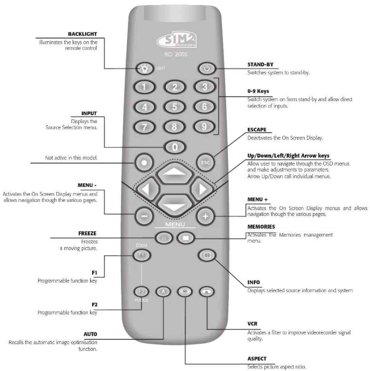
The remote control serves to control the system from a distance. The system is equipped with two infrared sensors, at the front and rear of the screen and on the front panel of the DigiOptic™ Image Processor.
Avoid placing obstructions between the remote control and the infrared sensor: this will impair the link between the two units. The remote control requires four 1.5V AAA alkaline batteries. In -sert the batteries, taking care to match the polarity, as indicated in the battery compartment in the handset (Fig. 20). Change the remote control batteries if you experience difficulty in transmitting commands to the system. Remove the batteries from the remote control if it is to remain unused for a long period of time to avoid the risk of potentially harmful chemical leaks.
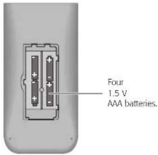
Fig. 20
8 ON-SCREEN MENU
All system functions can be activated from the keypad or remote control with the aid of a practical and comprehensive system of on screen menus.
INPUTS
The input selection menu is called by pressing 0 on the remote control and, when no other menu is displayed, also using the ▲ and ▼ keys on the keypad. To select an input, scroll through the list with the ▲ and ▼ keys until the required input is highlighted, then press ◀. Display of the input selection menu is terminated by pressing the ESC key or when the On-Screen Menu display timeout interval (set in the MENU SETUP) has elapsed.
Input 5 can receive RGB and YCrCb signals no higher than 32 kHz.
Inputs 6-7-8 can receive RGB and YCrCb signals, at 15 kHz, 32 kHz or higher. The association between the input and the type of signal is made on the pull-down menu that appears on the right of the < symbol after pressing the ◀ key (Fig. 21b).
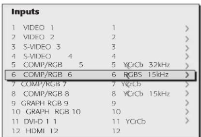
Fig. 21a
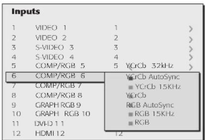
Fig. 21b
In the pull-down menu it is also possible to select the horizontal frequency manually or use the AutoSync option; in this case the system automatically recognises the input signal horizontal frequency
(15KHz, 32KHz or higher). Input 11 can receive YCrCb or RGB signals from DVI-D sources. The selection must be made on the pull-down menu following the previously illustrated system.
After selecting the source signal (by means of the ▲ and ▼ keys), press MENU+/MENU - to confirm and close the pull-down menu; the value you have just entered will be displayed to the right of the < symbol.
In general, the selection become operational for all inputs after pressing the ▶ key.
Once the input has been selected, a brief phase starts during which the system analyses the applied signal. During this interval a box appears with an indication relative to the signal requested. As soon as the system locks on to the signal the picture is displayed and a window appears containing information relative to the specific video format and standard (for video signals) or the resolution (for graphic signals).
In the SETUP menu you can select whether or not to display this information; for further details refer to the SOURCE INFORMATION heading in the "MENU" section.
MAIN MENU
To access the main On Screen Display menu, press the MENU key on the keypad or the MENU+ or MENU - key on the remote control. The main menu is divided into four windows, PICTURE, IMAGE, SETUP and MENU, in which the various adjustments are grouped according to the frequency of use. Use the ▶ and ◀ keys to select the line corresponding to the adjustment you wish to make (Fig. 22).
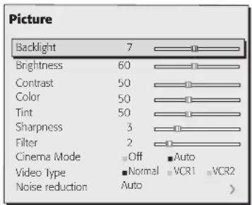
Fig. 22
The various menus offer only the relevant adjustments in accordance with the type of input signal displayed. For this reason, for example, when the source is a graphic signal certain typical adjustments for video signals do not appear on the menus, and vice versa when the source is a video signal.
Some adjustments (e.g. BRIGHTNESS and CONTRAST) are associated with a numerical value that can be varied within the set limits using the ▶ and ◀ keys. For others (e.g. VIDEO TYPE) you can choose between two options presented on the same line (and selectable using the ▶ and ◀ keys).
Other adjustments (identified by by the symbol < ) are associated with submenus, which appear as a superimposed window in which the selection is made with the and keys (Fig.23).
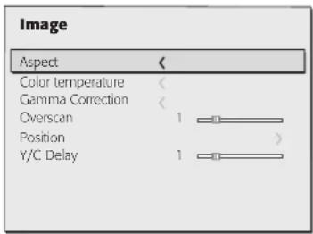
Fig. 23A
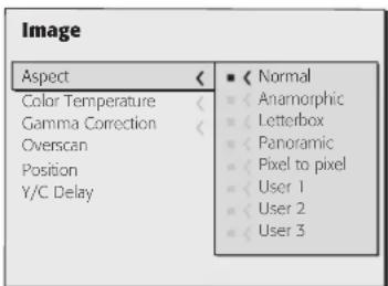
Fig. 23B
These submenus are accessed by pressing the < key. To quit the submenu and return to the higher level press the MENU+/- keys. Press ESC on the remote control or keypad to abandon the menu display or wait for it to disappear automatically after the number of seconds set in the SETUP page.
PICTURE
This menu features the adjustments related to picture quality. Adjustments that are not available for a specific input will not be displayed on the menu. Table 3 summarises the adjustments available for each input. For a complete overview of the on-screen menus, consultation SCREEN MENU LAYOUT' in the "ADDITIONAL INFORMATION" section.
BRIGHTNESS
Use this control to adjust the darker areas of the picture (black level), without significantly affecting bright areas. For correct adjustment it may prove useful to display a grey scale with at least twenty bands. Now try to reduce the brightness of the black band as much as possible while ensuring that it can still be distinguished from the adjacent band with brightness slightly higher than black. Alternatively use a scene composed of black objects alongside other dark coloured objects and try to keep all the objects separately identifiable.
CONTRAST
Use this control to adjust the brighter areas of the image (white level), without significantly affecting dark areas. For correct adjustment it may prove useful to display a grey scale with at least twenty bands. Now try to increase the brightness of the white band as much as possible while ensuring that it can still be distinguished from the adjacent band with brightness slightly less than white. Alternatively use a scene composed of well-lit white objects surrounded by light coloured objects with lower level lighting, and try to ensure that all the objects remain separately identifiable.
COLOUR
This control (also called Saturation) increases or decreases the picture colour intensity. When set to zero, colour images will be shown in black and white. Increasing the value, try to find the point at which the colours look natural: suitable references include skin tones and grass in landscape shots.
TINT
Controls the purity of colours. Basically determines the red-green ratio of the picture.
Reducing the value will boost the red contents of the picture, in -creasing it will boost the green tones. For this adjustment use skin tones or a test card image with colour bars as a reference.
SHARPNESS
This adjustment serves to modulate the signal to increase or decrease the level of picture detail. When the sharpness value is reduced the image details appear less pronounced, while increasing the value raises image definition, making the outline of objects sharper. Note that an excessively high value may result in a 'noisy' picture and the edges of objects may appear unnaturally clearly defined.
SHARPNESS MODE
This allows you to select the type of processing associated with sharpness adjustment. In the case of a progressive or interlaced video signal VIDEO mode is advisable; with PC graphic signals use GRAPHIC mode.
FILTER
This allows you to select the mode in which the input signal is processed.
Selecting the most appropriate value for a given input signal ensures the best horizontal and vertical definition and makes the picture sharper.
CINEMA MODE
Use this option if the video signal source is a movie film (obtained from a Teleciné device with 3:2 or 2:2 pull-down). In this case a deinterlace algorithm optimized for this type of signal is applied. Selecting AUTO mode causes the de-interlacer to analyse signal characteristics and apply the correct deinterlace mode automatically. Selecting the NO option causes the de-interlacer to apply a Motion compensated algorithm optimized for video camera signals.
VIDEO TYPE
Inserts a filter that improves stability of images from videorecorders or DVD players. To toggle between NORMAL and VCR mode, press the 🔗 key on the remote control or select the value on the On Screen Display.
NOISE REDUCTION
This adjustment serves to select the noise reduction filter value. When the option is selected in the menu the picture is divided into two. On the left hand side the picture is not affected by the filter while the filter is active on the right hand side; this makes it possible to compare the changes resulting from noise filtration with a clean unfiltered image. It is possible to deactivate the filter (NOT ACTIVE) using the automatic (AUTO) setting or manually (MANUAL) selecting the most suitable value for the picture with the VALUE adjustment. In this latter case it is sufficient to position the cursor under the values and make the required setting with the ▶ e ◀ keys on the remote control. A specific function (SKIN TONES ADJUSTMENT) can be used in conjunction with NOISE REDUCTION in order to make skin tones appear more natural. In fact, it is frequently the case that the reduction of noise is accompanied by a slight degradation of the picture in skin tone areas, while using this function makes it possible to obtain optimum quality of the entire picture.
Table 3
| Adjustments | Inputs | |||||
| Video S-V video | RCBS 15kHz YCrCb 15kHz | RCBS | YCrCb | RCB Grafico | DVHD HDMTM | |
| Brightness | ● | ● | ● | ● | ● | ● |
| Contrast | ● | ● | ● | ● | ● | ● |
| Colour | ● | ● | - | ● | - | - |
| Tint | ○ | ● | - | ● | - | - |
| Sharpness | ● | ● | ● | ● | ● | ● |
| Sharpness Mode | - | - | ● | ● | ● | ● |
| Filter | ● | ● | - | - | - | - |
| Cinema Mode | ● | ● | - | - | - | - |
| Video Type | ● | ● | - | - | - | - |
| Noise reduction | ● | ● | - | - | - | - |
| Flesh tone correction | ● | ● | - | - | - | - |
- Present only if the Video Standard is NTSC
IMAGE
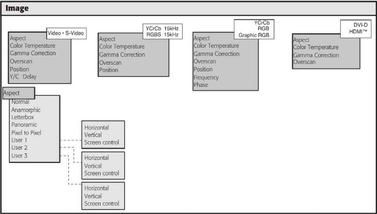
This menu features adjustments relating to picture position, aspect ratio, magnification etc.
ASPECT
This adjustment allows you to change the dimensions and aspect ratio (relationship between width and height) of the displayed image. There are five preset aspects available and three personalised aspects (with user-settable parameters). You can select a different aspect for each source: the selected aspect ratio will be automatically called the next time the relative source is called. You can also select the required aspect ratio by repeatedly pressing the ◀, or by pressing and numerical key (1...8). The following aspects are available.
NORMAL: projects the image occupying the full height of the screen while maintaining the aspect ratio of the input signal. When the input signal aspect ratio is 4:3 black vertical bands are displayed on the right and left of the picture.
ANAMORPHIC: allows a 16:9 picture to be displayed correctly.
LETTERBOX: serves to display a 4:3 letterbox image (with source signal having black bands above and below the picture) so that it fills the 16:9 screen and maintains the correct aspect ratio.
PANORAMIC: stretches the 4:3 image, slightly cropping the upper and lower parts. Panoramic is ideal for displaying a 4:3 image on the 16:9 screen of the Display.
PIXEL TO PIXEL: displays the image as it is input without adapting it to the screen.
The image is projected in the centre of the screen and if its horizontal and/or vertical dimensions are smaller than the display, it is bounded by vertical and/or horizontal black bands.
USER 1, 2, 3: when none of the preset formulas are suitable, the User formulas are available, with the facility for continuous horizontal and vertical adjustment of picture size.
COLOUR TEMPERATURE
Changes the colour balance of the image and is referred to the colour temperature of white. Colours can be adjusted towards the red end of the spectrum (low colour temperature values - expressed in degrees Kelvin) or the blue end (high values). Colour temperature can be selected with three preset values: HIGH, MEDIUM and LOW. In addition, a USER setting is provided in which the user can set the white point by making separate adjustments for Red, Green and Blue. Generally, the HIGH value is more suitable for displaying graphic images, while MEDIUM and LOW values are preferable for video images.
GAMMA CORRECTION
Determines the system's response to the grey scale, emphasising or attenuating the different grades of brightness (blacks, dark, medium, light grey, whites) in the projected image. The GRAPHIC setting is more suitable for computer images, while the VIDEO and FILM settings are more suitable for video images.
OVERSCAN
Eliminates irregularities around the outer borders of the image. Certain relatively inaccurate sources can produce an image with more or less pronounced irregularities around the outer edges; thanks to the overscan function these imperfections can be moved to outside the displayed area. Overscan values can be between 0 (no overscanning) and 32 (maximum overscanning). The resulting image always maintains the selected aspect irrespective of the selected overscan value.
POSITION
Use this adjustment to position the image vertically and horizontally. Determines the aspect of the displayed image.
These parameters do not normally require adjustment because the system examines the input signal and automatically sets the most suitable values. However, if the image is not perfectly centralised it may prove useful to repeat the input signal analysis and the consequent image positioning procedure. This automatic control procedure is activated by pressing key "A" on the remote control. When this procedure is called it is helpful to have a white or light coloured background on the screen in the current picture.
FREQUENCY/PHASE
These adjustments, available for progressive signals and for signals from a PC, ensure correspondence between the number of pixels making up the signal and the number of pixels that make up the projected image.
These parameters do not normally require adjustment because the system examines the input signal and automatically sets the most suitable values. However, if the image appears disturbed (loss of resolution within equidistant vertical bands or instability and lack of sharpness on narrow vertical lines) it may help to prompt the system to repeat the input signal analysis and consequent determination of the frequency and phase parameters. This automatic control procedure is activated by pressing key "A" on the remote control. If the automatic procedure fails to have the required effect, enter the frequency and phase values manually and move sufficiently near to the screen to observe the effects of the adjustments.
Y/C DELAY
In the case of Video and S-Video signals, it may be necessary to correct horizontal colour misalignment within the projected image. For a given video standard (e.g. PAL or NTSC) the stored value does not normally require further fine-tuning, unless the source or connection cable is changed.
Table 4
| Adjustments | Input | |||||
| Video S-Video | RGBS 15kHz YCrC5 15kHz | RCBS | YGCb | RCB Grafico | DWHD HDWIVW | |
| Position | ● | ● | ● | ● | ● | - |
| Aspect | ● | ● | ● | ● | ● | ● |
| Frequency | - | - | ● | ● | ● | - |
| Phase | - | - | ● | ● | ● | - |
| Color Temperature | ● | ● | ● | ● | ● | ● |
| Gamma correction | ● | ● | ● | ● | ● | ● |
| Overscan | ● | ● | ● | ● | ● | ● |
| Y/C Delay | ● | ● | - | - | - | - |
SETUP
The setup menu contains less frequently used adjustments that may be required during installation (e.g. On Screen Display language selection or the display of Test Patterns).
POWER ON
If selected (AUTO), this option allows the system to be switched on directly from the mains power supply once the initialisation phase is terminated.
If disabled (STAND BY), at the end of the initialisation phase the system assumes Standby status and awaits the power-up command from the remote control or keypad.
TEST PATTERNS
Displays a series of five test patterns, which are useful when installing the system and checking basic functions. Use the ▲ and ▼ keys to browse through the test patterns
INITIAL SETTINGS
Restores original factory settings except for Position, Orientation, Y/C Delay, Zoom and Focus.
MENU
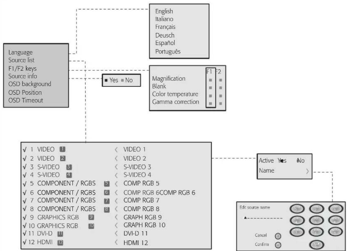
LANGUAGE
Lists the languages available for the On Screen Display menus.
INPUTS LIST
In order to make the HTL40 LINK system increasingly flexible, the functions described below make it possible to modify the inputs selection menu and adapt it so that it matches the requirements of the user more closely.
The main page displays all the inputs physically present on the DigiOptic™ Image Processor.
If one or more of the inputs is not used, they can be hidden in the list, which is called by pressing the 0 key.
For this purpose select SOURCES LIST and position the cursor on the line corresponding to the input you wish to hide. Now press the
◀ key and select activation or deactivation of the relative source (Fig.24).
The deactivation or activation of the source results in automatic renumbering of the remaining active inputs.
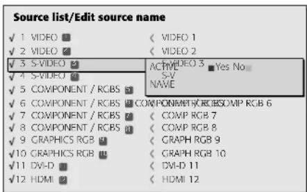
Fig.24
Active video signal sources (shown in the inputs selection menu) are distinguished by tick symbols.
You can also identify the input with a more significant name for the user (e.g. with the name of the connected device).
The current source can be renamed in the pull-down menu.
For this purpose, after selecting the display of a given input, select the option Name. This function is designed to facilitate the identification of a source connected to a particular input.
To assign a name to a source you can use up to twelve alphanumeric characters (for more details refer to the following section).
TEXT INSERT
Characters are entered using a specific text input menu (Fig.25). This menu provides the facility to store text strings easily and quickly.
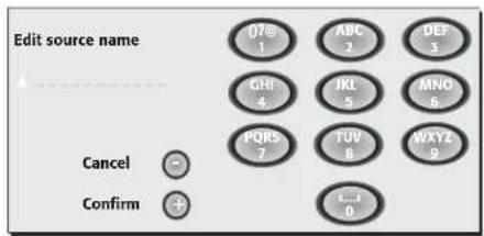
Fig.25
Text input mode is same whether you are editing an existing name or entering a name for the first time. Characters can be inserted in any of the available positions (represented by horizontal lines).
Use the ◀ and ▶ keys to move the cursor left or right respectively. Press the numerical key corresponding to the character (Fig. 26); the first press selects the first character, the second press selects the second character, and so forth.
The available characters are shown in the text insert menu that appears in this input mode.
Once you have entered a character, to enter the next character move the cursor to a position immediately to the right by means of the ▶ key on the remote control and repeat the procedure described above.
Use the ▲key to switch from upper case to lower case characters.
To delete any errors move the cursor to the incorrect character and press the ▼ key.
Once you have terminated the text input procedure confirm your text and save it by pressing the MENU+ key on the remote control. If you want to cancel the changes you have made press the MENU- key.
F1-F2 KEYS
The remote control is equipped with two keys (F1 and F2) which are associated with various different functions.
To consult the available functions select the option F1/F2 KEYS to display a table in which the items on the rows describe the functions that can be assigned to keys F1 and F2, which are represented by the table columns.
Choose the required column using the ◀ and ▶ keys on the remote control; this will enable you to identify one of the two keys F1 or F2; now select the function to assign to the key (F1 or F2) by means of the ▲ and ▼ keys on the remote control.
The function performed by the key is confirmed by the appearance of a dot on the corresponding column-row intersection.
The functions available for keys F1 and F2 are described below.
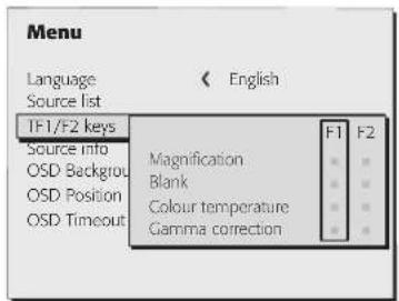
Fig.26
MAGNIFICATION
Selects the electronic zoom function. Use the ▲ and ▶ keys to adjust image magnification. If the key is pressed a second time you will activate PAN mode in which the ▲ and ▼, ▶ and ▶ keys enable you to pan over the magnified image.
BLANK
Switches off the video signal and displays a black page. As soon as the key is pressed an OSD indication lasting a few seconds confirms that the function has been activated. Pressing any further keys on the remote control restores the previous conditions.
COLOUR TEMPERATURE
Successive pressing of the key in question F1(or F2) makes it possible to select a different colour temperature.
GAMMA CORRECTION
Successive pressing of the key in questionF1(or F2) makes it possible to select from among the available gamma curves.
SOURCE INFORMATION
When active (YES) each time the source is changed information is displayed relative to the signal type. When disabled(NO) no information is displayed relative to the selected source when the source is changed.
OSD BACKGROUND
Determines the type of background for the On Screen Display.
OSD TIMEOUT
Determines the On Screen Display timeout. When the On Screen Display appears it will remain displayed for the time set in this parameter starting from the time the last key was pressed. The adjustment is made using the ◀(decrease) and ▶(increase) keys within a 5-60 second timeframe.
OSD POSITION
Serves to position the On Screen Display within the screen area. The OSD can be positioned using the arrow keys for fine adjustments or keys 1...9 on the remote control to select one of 9 preset positions.
MEMORIES
The main picture parameters can be saved in discrete sets of values called "Memories" so that they can be subsequently applied as a group using a single command.
3 separate Memories (Memory 1, Memory 2, Memory 3) are available for each of the 25 types of signals:
| 1 VIDEO | |
| 2 VIDEO | |
| 3 S-VIDEO | |
| 4 S-VIDEO | |
| 5 COMP/RCB(YCrCb 15KHz) | 5 COMP/RGB(RGB 15KHz) |
| 5 COMP/RCB(YCrCb 32KHz) | 5 COMP/RGB(RGB 32KHz) |
| 6 COMP/RCB(YCrCb 15KHz) | 6 COMP/RGB(RGB 15KHz) |
| 6 COMP/RCB(YCrCb) | 6 COMP/RGB(RGB) |
| 7 COMP/RCB(YCrCb 15KHz) | 7 COMP/RGB(RGB 15KHz) |
| 7 COMP/RCB(YCrCb) | 7 COMP/RGB(RGB) |
| 8 COMP/RCB(YCrCb 15KHz) | 8 COMP/RGB(RGB 15KHz) |
| 8 COMP/RCB(YCrCb) | 8 COMP/RGB(RGB) |
| 9 GRAPHICS RGB | |
| 10 GRAPHICS RGB | |
| 11 DVI-D (RGB) | |
| 11 DVI-D (YCrCb) | |
| 12 HDMI |
for a total of 75 memories.
The image parameters that can be stored/retrieved by the Memories management system are as follows:
Image Picture
BRIGHTNESS ASPECT
CONTRAST COLOUR TEMPERATURE
COLOUR OVERSCAN
TINT GAMMA
SHARPNESS
FILTER
SHARPNESS MODE
VIDEO TYPE
NOISE REDUCTION
Some of these parameters may not be available for certain inputs or certain input signals, in accordance with the definitions in Tables 3 and 4.
Pressing the ■ key on the remote control or the key on the keypad (Fig.27) serves to activate the menus management menu page.
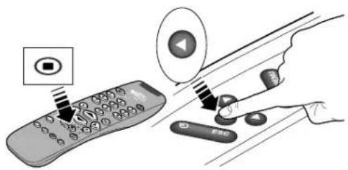
Fig.27
The available operations for each selected memory are described below.
SAVING A MEMORY
To save the image parameter current values in memory 1, move the cursor to line '1' with the ▲ and ▼ keys and open the pull-down menu by pressing the ▲ ]key (Fig.28). Select the line SAVE CURRENT SETTINGS. To confirm the operation, the message Current settings saved in Memory 1 is displayed at the bottom of the screen and the letter S appears to the left of the memory name. Memories 2 and 3 can be saved using the same procedure.
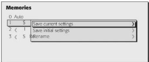
Fig.28
RECALL MEMORIES
To retrieve memories select the required line and press the ▶ key. The parameters stored in the selected memory will be applied to the displayed image, while a confirmation message will be displayed to confirm the operation 'MEMORY I RECALLED.' The retrieved memory is associated with the specific source and signal type and called automatically whenever that specific combination of source and signal type is selected.
RESTORE MEMORIES
To restore the original values of a previously modified Memory, select the line relative to the Memory in question and open the corresponding drop-down menu ▲ key). Select the line 'SAVE INITIAL SETTINGS'. To confirm the operation, the messageINITIAL SETTINGS SAVED IN MEMORY 1' is shown at the bottom of the display and the letter "I" appears to the left of the memory name.
RENAME MEMORIES
All Memories can be named. To enter a name (maximum length of 12 alphanumeric characters) select the option 'Rename' in the relative drop-down menu. The text is input in accordance with the method described in the heading "TEXT INSERT".
RESTORE CURRENT VALUES
When you open the "MEMORIES" menu a copy of the current settings is saved in a temporary memory (designated by 0-AUTO). After having retrieved one or more memories you can restore the settings existing at the time you opened Memories menu by selecting Memory '0' (0-AUTO). Note that this operation must be executed before the Memories' menu page disappears (30 seconds after the final operation with the remote control or keypad). The next time it appears, in fact, the temporary memory will contain new information that takes account of any Memories that were selected in the penultimate access to the 'MEMORIES' page.
Memory 0 can be used even when you do not wish to enable Memories management for the signal in use. In effect, once it is selected, when a source is chosen the system will automatically reload the settings that were active the last time the memory was retrieved.
INFO
Displays information concerning the displayed video/graphic signal and the operating status of the system.
This function is displayed on pressing the i key on the remote control (or, in the absence of the On Screen Display, the ▶ key on the keypad).
QUICK MENUS
The quick menus provide access to the main adjustments that affect image quality without calling the main menu.
Brightness, CONTRAST, COLOUR, TINT, SHARPNESS and FILTER adjustments appear at the bottom of the screen one after the other when the
▲ and ▼keys are pressed.
MESSAGES
The following messages may appear during operation of the system:
No Signal
The system does not recognise any signal applied to the selected input. In this case:
- Make sure the selected input is connected to a video or graphic signal and that that source is functioning correctly.
- Check the condition of the cables used to connect the system to the various sources.
- Make sure the video or graphic signals supplied by the source are compatible with the system's technical specifications and, in particular, with those of the selected input.
Out of range
This message appears when either the resolution or the vertical/horizontal frequency of the input signal exceeds system specifications (e.g. a QXGA graphic signal) or when an input is supplied with an incompatible signal (e.g. after setting the components input to YCrCb 15kHz a progressive signal is connected).
9 CLEANING AND MAINTENANCE
The screen and the DigiOptic™ Image Processor do not require internal adjustments and do not contain any user-serviceable parts.
For any service requirements seek qualified technical assistance from your nearest Dealer.
To clean the outer cover of the screen use a soft cloth and moisten slightly if necessary with water and a small amount of neutral soap. Do not rub hard on the printed captions on the rear panel of the DigiOptic™ Image Processor.
The screen may be cleaned with a very soft non-abrasive brush in order to remove dust particles. Alternatively, use a soft dry cleaning cloth (of the type used to clean spectacles) to remove fingerprints and grease marks.
10 TROUBLESHOOTING GUIDE
No power (LEDs always OFF)
- Check that the units' power switches are set to "I".
- Check that the power cables are correctly connected to the units' power sockets.
- Check the condition of the fuse located on the power socket on the rear of the screen.
- Replace the fuse located on the screen power socket with an equivalent and identically rated fuse (T3,15A H).
- If the fuse blows repeatedly, seek technical assistance from your nearest Dealer.
No picture
- Make sure the selected input is connected to a video or graphic signal and that the relevant source is functioning correctly.
- Make sure the video or graphic signals supplied by the source are compatible with the HTL40 LINK technical specifications and, in particular, with the selected DigiOptic™ Image Processor input.
- Check the condition of the cables used to connect the DigiOptical™ Image Processor to the various sources.
- Check the state of the connection between the DigiOptical™ Image Processor and the screen.
- Check the state of the connection by interpreting the code displayed by the system LEDs in accordance with Table 2.
- Make sure the cooling air vents on the units are not blocked and that the ambient temperature is below 35^ C.
Image is disturbed, unstable or noisy
- Make sure the video or graphic signals supplied by the source are compatible with the system's technical specifications and, in particular, with those of the selected input.
- Check the condition of the cables used to connect the DigiOpti-
cal™ Image Processor to the various sources.
- If the problem occurs on a terrestrial broadcast source signal, check that the receiver has been correctly tuned in and that the aerial system is in good working order.
- If the problem occurs in a video signal from a videorecorder, ensure that the videotape is an original "first generation" copy and that VCR mode is active in the PICTURE menu.
- Adjust the Sharpness parameter in the PICTURE menu to optimise the displayed image.
Incomplete image along borders (vertical and horizontal)
- Make sure the video or graphic signals supplied by the source are compatible with the system's technical specifications and, in particular, with those of the selected input.
- Recall the automatic image adjustment function by pressing the key "A" on the remote control or the AUTO key on the screen keypad.
- Adjust the horizontal or vertical position of the displayed image using the IMAGE/POSITION menu.
- Adjust the width and height of the image, selecting Aspect in the IMAGE/ASPECT menu.
- Adjust the overscan value applied to the image on the IMAGE/OVERSCAN menu.
Image too dark, too pale or unnaturally coloured
- Make sure the video or graphic signals supplied by the source are compatible with the system's technical specifications and, in particular, with those of the selected input.
- Adjust the CONTRAST, BRIGHTNESS, COLOUR and TINT parameters in
the PICTURE menu.
- If necessary, adjust COLOUR TEMPERATURE and GAMMA CORRECTION (IMAGE MENU).
Graphic image with poor quality vertical detail
- Make sure the video or graphic signals supplied by the source are compatible with the system's technical specifications and, in particular, with those of the selected input.
- Press key "A" on the remote control or the AUTO key on the screen keypad to execute automatic adjustments.
- Adjust FREQUENCY and PHASE parameters in the IMAGE menu to optimise the vertical detail of the displayed image.
Video Image showing colour misalignment on vertical details
- Make sure the video or graphic signals supplied by the source are compatible with the system's technical specifications and, in particular, with those of the selected input.
- Adjust Y/C DELAY settings in the IMAGE menu to reduce colour misalignment.
Remote control not working
- Check remote control battery power and correct polarity.
- Ensure the area between the infrared sensors (on the front panel of the DigiOptic™ Image Processor and on the front of the screen) is free from obstructions.
- Make sure the infrared sensors on the front panel of the DigiOptic™ Image Processor and at the front of the screen are not exposed to intense light sources.
11 OPTIONAL ACCESSORIES
You can purchase the HTL40 LINK screen support base from your dealer as optional accessory.
Use only original or SIM2 Multimedia approved accessories.
CAUTION: for wall installation, by means of suspension bracket, carefully follow the instructions and safety instructions provided by the Manufacturer and supplied together with the bracket.
12 ADDITIONAL INFORMATION
A TECHNICAL SPECIFICATIONS
Screen
DISPLAY
Technology Thin Film Transistor - Liquid Crystal Dis play
Resolution: 1366x768x3 pixel, 3147264 pixels for high definition images
Dimensions : 40", image aspect 16:9 native
Brightness: 600 cd/m2
Contras : 1000:1
Vertical viewing angle: +/- 85°
Horizontal viewing angle: +/- 85°
Typical response time: 8ms
Lamp life time: 60000 hours under standard brightness conditions
ELECTRONICS
Input/Output: 3-channel fibre optic link
Control: Panel (keypad), remote control
GENERAL
Power supply cable: (EU, UK and US); length 2 m
Supply: from 120 to 240 Vac, +/-10% tolerance
Frequency: 48 to 62 Hz
Peak current: 30 A max
Consumption: 200 W max
Fuse: T 3.15A H. 5 x 20 mm
Screen dimensions: 1106x656x103 mm (LxHxD)
Weight (approx.): 35 kg
Packing: 1230x520x740mm
Operating temperature: 10 to 35 °C
Transportation temp.: -15 to 55 °C
Storage temperature: -15 to 55 °C
Humidity: 20% to 95% non-condensing
Safety: EN 60950, UL 60950
Transportability: "desktop equipment"
Electromagnetic comp.: EN 55022 Class B
EN 55024
EN 61000-3-2
EN 61000-3-3
Transportation: IEC 68-2-31, IEC 68-2-32
Digioptic™ Image Processor
ELECTRONICS
Input signals:
• 2 COMPOSITE VIDEO (CVBS)
RCA type connectors, gold-plated
1.0 V pp / 75 Ω, negative synchronisation.
• 2 S-VIDEO (Y/C)
4-pin mini-DIN connectors
Y: 1.0 V pp / 75 Ω, negative synchronisation
C: 0.286 Vpp / 75 Ω, [NTSC nominal burst level]
0.3 Vpp / 75 Ω [PAL, SECAM nominal burst level]
• 4 COMPONENTS (Y/Cr/Cb/H/V) - RGBHV
3 sets of 5 RCA connectors, gold-plated
1 set of 5 BNC type connectors, gold-plated
- Components signal
Y: 1.0 Vpp / 75 Ω, negative or 3-level synchronisation [HDTV]
Cr,Cb:0.7V_pp / 75
- RGB signal
R,B: 0.7 Vpp / 75 Ω
G: 0.7 Vpp / 75 Ω, separate H/V Sync or H+V Sync
1.0 Vpp / 75 Ω, negative or 3-level synchronisation [HDTV]
H,V: positive or negative TTL, 0.3-5 Vpp / 1 kΩ
• 2 RGBHV (analogue RGB)
female DB15HD connectors
R,B: 0.7 Vpp/75 Ω
G: 0.7 Vpp / 75 Ω, separate H/V Sync or H+V Sync
1.0 Vpp / 75 Ω, negative or 3-level synchronisation [HDTV]
H,V: positive or negative TTL, 0.3-5 Vpp / 1 kΩ
• 1 DVI (digital RGB-YCrCb )
DVI-D female connector
• 1 HDMI™
• 1 Optical S/PDIF Audio Output
TOSLINK connectorInput/Output:
Input/Output: 3-channel fibre optic link
Control: Panel (keypad), remote control, via RS232 from PC or home automation devices
Horizontal frequency: from 15 to 80 kHz (up to UXGA, 60 Hz)
Vertical frequency: 48 -100 Hz
Video standards: automatically selected
(PAL, B,G,H,I,M,N,60, SECAM, NTSC 3.58 and 4.43)
High definition video: ATSC HDTV (480p, 720p, 1080i, 1080p)
Graphic standards : VGA, SVGA, XGA, SXGA, UXGA
Deinterlacer: Faroudja chipset, DCDi™, 3:2 pull down sequence conversion
Control: infrared remote control, RS232 serial (DB9 connector, female)
Outputs: 2 12-V jack connector outputs (1 active with system powered on, 1 active with 16:9 aspect ratio selected)
GENERAL
| Power supply cable: | (EU, UK and US); length 2 m |
| Power supply: | 100 to 240 VAC, tolerance ± 10%, frequency 48 to 62 Hz |
| Peak current: | 30A max |
| Consumption: | 30W max |
| Dimensions: | 483 x 55 x 200 mm (WxHxD); compatible with 19" rack |
| Weight (approx.): | 2.5 kg |
| Operating Temperature: | 10 to 35 °C |
| Transportation temper.: | -15 to 55 °C |
| Storage temperature: | -15 to 55 °C |
| Humidity: | 20% to 95% non-condensing |
| Safety: | EN 60950, UL 60950 |
| Transportability: | desktop equipment |
| Electromagnetic compat.: | EN 55022 Class B |
| EN 55024 | |
| EN 61000-3-2 | |
| EN 61000-3-3 | |
| Transport: | IEC 68-2-31, IEC 68-2-32 |
Link cable
| Composition: | three 50/125μ multimode fibre optic cables |
| Connectors: | LC type |
| Length: | 20.0±0.2m |
| Diameter: | 5 mm max |
| Tensile strength: | 1200N* |
| Type Approval: | UL OFNP |
*traction applied on outer cable, not on fibre cores or connectors.
B DIMENSIONS
SCREEN
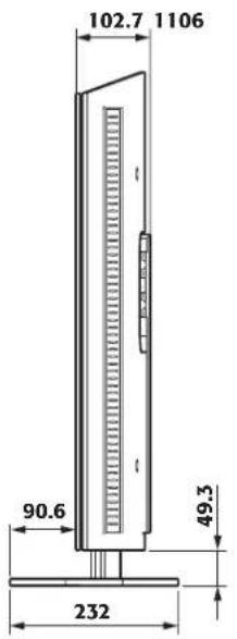
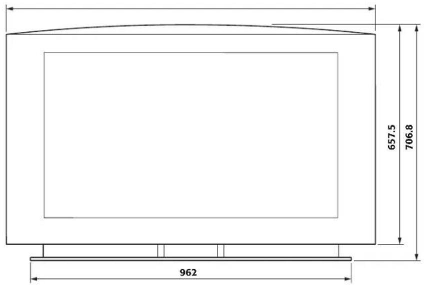
Unit of measurement: mm
DIGIOPTIC™ IMAGE PROCESSOR

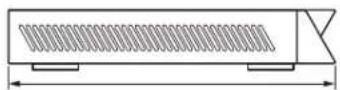
Unit of measurement: mm
flowchart
graph TD
    A["Backlight\nBrightness\nContrast\nColor\nTint\nSharpness\nFilter\nCinema Mode\nVideo Type\nNoise reduction"] --> B["Video • S-Video [NTSC"]\nYCrCb15kHz\nRGBS 15kHz]
    B --> C["Backlight\nBrightness\nContrast\nColor\nSharpness\nFilter\nFilter\nVideo Type\nNoise reduction"]
    C --> D["Video • S-Video [PAL, SECAM"]]
    D --> E["YCrCb"]
    E --> F["Brightness\nContrast\nSharpness\nSharpness Mode"]
    F --> G["RGBS\nGraphic RGB\nDVI-D\nHDMI™"]
    G --> H["Value\nFlesh tone correction\n■ On ▼ Off"]
    H --> I["■Not active ▼ Auto ▼ Manual"]
    I --> J["Flesh tone correction ▼ On ▼ Off"]
    J --> K["■Not active ▼ Auto ▼ Manual"]
flowchart
graph TD
    A["Image"] --> B["Aspect"]
    B --> C["Video • S-Video"]
    B --> D["YCrCb 15kHz RGBS 15kHz"]
    B --> E["YCrCb RGB Graphic RGB"]
    B --> F["DVI-D HDMI™"]
    G["Aspect"] --> H["Normal Anamorphic Letterbox Panoramic Pixel to Pixel User 1 User 2 User 3"]
    G --> I["Horizontal Vertical Screen control"]
    G --> J["Horizontal Vertical Screen control"]
    G --> K["Horizontal Vertical Screen control"]
    L["Aspect"] --> M["Color Temperature Gamma Correction Overscan Position Y/C Delay"]
    L --> N["Color Temperature Gamma Correction Overscan Position"]
    O["Aspect"] --> P["Color Temperature Gamma Correction Overscan Position Frequency Phase"]
    O --> Q["Color Temperature Gamma Correction Overscan Position Frequency Phase"]
Setup
Power ON
Test patterns
Initial Settings
Auto
Stand-by
Menu
flowchart
graph TD
    A["Language Source list\nF1/F2 keys\nSource info\nOSD background\nOSD Position\nOSD Timeout"] --> B{■ Yes □ No}
    B --> C["English\nItaliano\nFrançais\nDeusch\nEspañol\nPortuguês"]
    B --> D["Magnification F1 F2\nBlank\nColor temperature\nGamma correction"]
    D --> E["✓ 1 VIDEO 1 < VIDEO 1\n✓ 2 VIDEO 2 < VIDEO 2\n✓ 3 S-VIDEO 3 < S-VIDEO 3\n✓ 4 S-VIDEO 4 < S-VIDEO 4\n✓ 5 COMPONENT / RGBS 5 < COMP RGB 5\n✓ 6 COMPONENT / RGBS 6 < COMP RGB 6COMP RGB 6\n✓ 7 COMPONENT / RGBS 7 < COMP RGB 7\n✓ 8 COMPONENT / RGBS 8 < COMP RGB 8\n✓ 9 GRAPHICS RGB 9 < GRAPH RGB 9\n✓ 10 GRAPHICS RGB 10 < GRAPH RGB 10\n✓ 11 DVI-D 11 < DVI-D 11\n✓ 12 HDMI 12 < HDMI 12"]
    D --> F["Active Yes No Name"]
    F --> G["Edit source name"]
    G --> H["Cancel"]
    G --> I["Confirm"]
Memories
Memories
0 Auto
1 < S MEMORY 1 >
2 < S MEMORY 2 >
3 < S MEMORY 3 >
Save current settings
Save initial settings
Rename
Edit memory name
2、公司董事会会议决议公告
Cancel
Confirm


SUMMARY
| 1 INTRODUCTION 3 | |
| 2 IMPORTANT SAFETY INSTRUCTIONS 5 | |
| 3 UNPACKING 9 | |
| Pack contents 10 | |
| 4 INSTALLATION 11 | |
| Positioning the two units 11 | |
| Connecting the two units 14 | |
| Connecting the video sources 15 | |
| 5 SWITCHING ON AND OFF 18 | |
| Switching on/off from stand-by | 19 |
| 6 KEYPAD | 20 |
| 7 REMOTE CONTROL | 20 |
| 8 ON SCREEN MENUS | 21 |
| Inputs | 21 |
| Main Menu | 21 |
| Picture | 22 |
| Image | 23 |
| Set up | 25 |
| Menu | 25 |
| Memories | 27 |
| Info | 28 |
| Quick menus | 28 |
| Messages | 28 |
| 9 CLEANING AND MAINTENANCE | 29 |
| 10 TROUBLESHOOTING GUIDE | 29 |
| 11 OPTIONAL ACCESSORIES | 30 |
| 12 ADDITIONAL INFORMATION | 31 |
| A Technical specifications | 31 |
| B Dimensions | 33 |
| C On-screen menus layout | 34 |

SIM2 Multimedia Spa. • Viale Lino Zanussi, 11 • 33170 Pordenone - ITALY
Phone +39.434.383.253-256 • Fax +39.434.383260-261
www.sim2.com • e-mail: info@sim2.it
SIM2 USA Inc. • 10108 USA Today Way • 33025 Miramar FL - USA
Phone +1.954.4422999 • Fax +1.954.4422998
www.sim2usa.com • e-mail: sales@sim2usa.com
- In accordance with the manufacturer's constant product development programme, product specifications and design are subject to changes without
- INTRODUCTION
- IMPORTANT SAFETY INSTRUCTIONS
- CAUTION!
- LAMP WARNING
- CLASS 1 LASER PRODUCT
- PARTS LIST
- - Read this manual carefully and keep it in a safe place for future consultation.
- - Do not touch internal parts of the units.
- • Power supply disconnect device.
- - Connect the unit only to the type of power supply indicated.
- - Connection of the units to the mains power supply.
- - Changing the fuses.
- Before changing the fuse disconnect the unit from the mains power supply.
- - Be careful with cables.
- - Disconnect the unit from the mains power supply in the event of electrical storms and when not in use.
- - Avoid contact with liquids and exposure to humidity.
- - Prevent the units from overheating.
- - Never look directly at the projection lamp.
- - Position the unit on a stable surface.
- - Do not insert objects through the openings in the unit.
- UNPACKING
- PACK CONTENTS
- INSTALLATION
- POSITIONING THE TWO UNITS
- Positioning the DigiOptic™ Image Processor
- Positioning the screen unit
- WALL MOUNTING
- TABLETOP INSTALLATION WITH SUPPORT BASE (OPTIONAL)
- Caution! Do not supply power to the panel by plugging the power cable into the mains socket outlet until you have finished the installation procedure.
- CONNECTING THE TWO UNITS
- CONNECTING THE VIDEO SOURCES
- VIDEO 1 2 3
- S-VIDEO 4 5
- COMPONENT / RGBS 6789
- GRAPHICS RGB 10 11
- DVI-D 12
- HDMI
- CONTROL (RS232)
- SWITCHING ON AND OFF
- Power-up sequence
- SWITCHING ON AND OFF FROM STAND BY
- KEYPAD
- Menu
- Auto
- REMOTE CONTROL
- ON-SCREEN MENU
- INPUTS
- MAIN MENU
- PICTURE
- BRIGHTNESS
- CONTRAST
- COLOUR
- TINT
- SHARPNESS
- SHARPNESS MODE
- FILTER
- CINEMA MODE
- VIDEO TYPE
- NOISE REDUCTION
- IMAGE
- ASPECT
- COLOUR TEMPERATURE
- GAMMA CORRECTION
- OVERSCAN
- POSITION
- FREQUENCY/PHASE
- Y/C DELAY
- SETUP
- POWER ON
- TEST PATTERNS
- INITIAL SETTINGS
- LANGUAGE
- INPUTS LIST
- TEXT INSERT
- F1-F2 KEYS
- MAGNIFICATION
- BLANK
- SOURCE INFORMATION
- OSD BACKGROUND
- OSD TIMEOUT
- OSD POSITION
- MEMORIES
- Image Picture
- SAVING A MEMORY
- RECALL MEMORIES
- RESTORE MEMORIES
- RENAME MEMORIES
- RESTORE CURRENT VALUES
- INFO
- QUICK MENUS
- MESSAGES
- No Signal
- Out of range
- CLEANING AND MAINTENANCE
- TROUBLESHOOTING GUIDE
- No power (LEDs always OFF)
- No picture
- Image is disturbed, unstable or noisy
- Incomplete image along borders (vertical and horizontal)
- Image too dark, too pale or unnaturally coloured
- Graphic image with poor quality vertical detail
- Video Image showing colour misalignment on vertical details
- Remote control not working
- OPTIONAL ACCESSORIES
- ADDITIONAL INFORMATION
- A TECHNICAL SPECIFICATIONS
- Screen
- DISPLAY
- ELECTRONICS
- GENERAL
- Digioptic™ Image Processor
- B DIMENSIONS
- SUMMARY
Brand : Sim2
Model : HTL40 LINK
Category : Television