GCL1916W - Unspecified IOGEAR - Free user manual and instructions
Find the device manual for free GCL1916W IOGEAR in PDF.

User questions about GCL1916W IOGEAR
0 question about this device. Answer the ones you know or ask your own.
Ask a new question about this device
Download the instructions for your Unspecified in PDF format for free! Find your manual GCL1916W - IOGEAR and take your electronic device back in hand. On this page are published all the documents necessary for the use of your device. GCL1916W by IOGEAR.
USER MANUAL GCL1916W IOGEAR
| Safety Instructions 4 | |
| Rack Mounting 5 | |
| Conventions | 6 |
| Introduction | 7 |
| Package Contents 7 | |
| Features | 8 |
| Requirements | 9 |
| Operating Systems 9 | |
| Overview | 10 |
| Hardware Setup 14 | |
| Operation | 20 |
| OSD Operation 27 | |
| Mouse and Keyboard Emulation 30 | |
| Hotkey Operation 37 | |
| Keyboard Emulation 43 | |
| Firmware Upgrade Utility 45 | |
| Specifications Chart 50 | |
| Trouble Shooting 52 | |
| Appendix | 53 |
| Limited Warranty 55 | |
| Compliance Information 55 | |
| Contact | 55 |
| FCC Information | 56 |
Safety Instructions
- Read all of these instructions. Save them for future reference
■ This device is for indoor use only
■ Follow all warnings and instructions marked on the device
■ Do not place the device on any unstable surface (cart, stand, table, etc.). If the device falls, serious damage will result
■ Do not use the device near water
■ Do not place the device near, or over, radiators or heat registers
■ The device cabinet is provided with slots and openings to allow for adequate ventilation. To ensure reliable operation, and to protect against overheating, these openings must never be blocked or covered
■ The device should never be placed on a soft surface (bed, sofa, rug, etc.) as this will block its ventilation openings. Likewise, the device should not be placed in a built-in enclosure unless adequate ventilation has been provided
■ Never spill liquid of any kind on the device
■ Unplug the device from the wall outlet before cleaning. Do not use liquid or aerosol cleaners. Use a damp cloth for cleaning
■ The device should be operated from the type of power source indicated on the marking label. If you are not sure of the type of power available, consult your dealer or local power company
■ The device is designed for IT power distribution systems 100-240V single phase voltage
■ To prevent damage to your installation, it is important that all devices are properly grounded
■ The device is equipped with a 3-wire grounding type plug. This is a safety feature. If you are unable to insert the plug into the outlet, contact your electrician to replace your obsolete outlet. Do not attempt to defeat the purpose of the grounding-type plug. Always follow your local/national wiring codes
■ Do not allow anything to rest on the power cord or cables. Route the power cord and cables so that they cannot be stepped on or tripped over
If an extension cord is used with this device, make sure that the total Ampere ratings of all products used on this cord does not exceed the extension cord Ampere rating. Make sure that the total of all products plugged into the wall outlet does not exceed 15 Amperes.
■ To help protect your system from sudden, transient increases and decreases in electrical power, use a surge suppressor, line conditioner, or un-interruptible power supply (UPS)
■ Position system cables and power cables carefully; Be sure that nothing rests on any cable
■ Never push objects of any kind into or through cabinet slots. They may touch dangerous voltage points or short out parts resulting in a risk of fire or electrical shock
■ Do not attempt to service the device yourself. Refer all servicing to qualified service personnel
■ If the following conditions occur, unplug the device from the wall outlet and bring it to qualified service personnel for repair
o If the power cord or plug has become damaged or frayed, unplug the device from the wall outlet and replace with new power cord
o Liquid has been spilled into the device
o The device has been exposed to rain or water
o The device has been dropped, or the cabinet has been damaged
o The device exhibits a distinct change in performance, indicating a need for service
o The device does not operate normally when the operating instructions are followed
■ Only adjust those controls that are covered in the operating instructions. Improper adjustment of other controls may result in damage that will require extensive work by a qualified technician to repair
- Do not connect the Audio Jack connector marked "UPGRADE" to a public telecommunication network
- Avoid circuit overloads. Before connecting equipment to a circuit, know the power supply's limit and never exceed it. Always review the electrical specifications of a circuit to ensure that you are not creating a dangerous condition or that one does not already exist. Circuit overloads can cause a fire and destroy equipment.
Rack Mounting
■ Before working on the rack, please make sure that the stabilizers are secure to the rack, extended to the floor, and that the full weight of the rack rests on the floor. Install the front and side stabilizers on a single rack or front stabilizers for joined multiple racks before working on the rack.
■ Always load the rack from the bottom up and load the heaviest item in the rack first
■ Please make sure that the rack is level and stable before extending a device from the rack
■ Use caution when pressing the device rail release latches and sliding a device into or out of a rack; the slide rails can pinch your fingers
■ Do not overload the AC supply branch circuit that provides power to the rack. The total rack load should not exceed 80 percent of the branch circuit rating
■ Make sure that all equipment used on the rack – including power strips and other electrical connectors – is properly grounded
■ Ensure that proper airflow is provided to devices in the rack
■ Ensure that the operating ambient temperature of the rack environment does not exceed the maximum ambient temperature specified for the equipment by the manufacturer
■ Do not step on or stand on any device when servicing other devices in a rack
■ Caution: Slide/rail (LCD KVM) mounted equipment is not to be used as a shelf or a work space

text_image
Prohibition sign with no text, featuring a crossed-out document and a bottle iconConventions
This manual uses the following conventions
Monospaced Indicates text that you should key in
[] Indicates keys you should press. For example, [Enter] means to press the Enter key.
- Numbered lists represent procedures with sequential steps
■ Bullet lists provide information, but do not involve sequential
steps
→ Indicates selecting the option (on a menu or dialog box, for example), that comes next. For example, Start → Run means to open the Start menu, then select Run
Indicates critical information
Introduction
IOGEAR's GCL1908W/GCL1916W is an 18.5" Widescreen Short Depth VGA LCD KVM Console with an 8 or 16 port integrated KVM switch and an integrated keyboard - touch pad. The short-depth design fits all 19" equipment cabinets, suitable for shallow racks and limited space setups. In addition to saving valuable space on the rack, the GCL1908W/GCL1916W also provides a space-saving solution for special environment such as Outside Broadcast Vans (OB Vans) and compact control rooms.
The GCL1908W/GCL1916W has dedicated front end sliding consoles, compatible with IOGEAR's VGA KVM Switches GCS1808 or GCS1716, capable of controlling up to 128/256 computers when cascaded. This widescreen short depth VGA LCD KVM console has single rail design with an 18.5" widescreen LCD monitor, an integrated keyboard and touchpad. GCL1908W/GCL1916W offers Broadcast mode, enables the console to spread out entered commands to all connected computers, efficient in performing operations simultaneously. In addition, the Auto Scan feature allows for continuous monitoring specific group of connected computers and establishing a reliable working environment for users.
For enhanced information safety, the GCL1908W/GCL1916W provides two-level password security which restricts unauthorized users from viewing and controlling the computers. Users can choose to manage the computer from an external console. Also for added convenience, the GCL1908W/GCL1916W comes with an additional hot-pluggable USB mouse port that only supports HID device for keyboard and mouse.
As a feature-rich LCD KVM Switch, the GCL1908W/GCL1916W is aimed not just to achieve but exceed the requirements for space utility optimization, superior video quality (1366 x 768), adaptive deployment, and operational versatility, and thus is ideal for control rooms with limited space in any industry.
Package Contents
GCL1908W/GCL1916W
- 1 x 8/16-Port 18.5" Widescreen Short Depth VGA LCD KVM Console
- 1 x USB KVM Cable
- 1 x PS/2 KVM Cable
• 1 x Standard Rackmount Kit
• 1 x Firmware Upgrade Cable - 1 x Grounding Wire
- 1 x Power Cord
- 1 x Quick Start Guide
Please verify that all components are present and nothing was damaged in shipping. If you encounter a problem, contact your dealer.
Read this manual thoroughly and follow the installation and operation procedure to prevent any damage to the unit, and/or any of the devices connected to it.
Features
- Integrated LCD KVM console with 18.5" widescreen LCD monitor in a single rail housing with top and bottom clearance for smooth operation in a 1U high system rack
- Integrated 8/16 ports VGA KVM Switch
- Control up to 128/256 computers by cascading up to 2 levels with IOGEAR's GCS1808 or GCS1716
• LCD monitor supports resolution of 1366 x 768 @60Hz - Short depth design allows for rack-mounting in narrow spaces
• Supports VGA video input; supports an external console with USB/VGA connectors
• Built-in USB Type-A port on front panel for peripheral sharing HID devices - Dual Interface – Supports computers with PS/2 or USB Keyboards and Mice
• Auto PS/2 and USB interface detection - Keyboard and mouse emulation (PS/2 and USB) for smooth switching and simultaneously booting multiple computers even when the console's focus is elsewhere
- Console lock design enables the console drawer to remain securely locked away in position when not in use
- Computer selection via pushbuttons, hotkeys, and multilingual On Screen Display (OSD)
- Broadcast mode – enables to send commands from the console to all connected computers to perform simultaneous operations
- Two level password security – only authorized users can view and control computers
- Auto Scan Mode – enables continuous monitoring of user-selected computers
- Multilingual keyboard mapping supports English (US), English (UK), French, German, German (Swiss), Hungarian, Italian, Japanese, Korean, Russian, Spanish, Swedish, and Traditional Chinese
- Standard rack mount kit included
- Plug-n-Play
- Firmware Upgradable
- Hot Pluggable
Requirements
Computers
• VGA, SVGA, or MultiSync video graphics card with an HDB-15 port
- PS/2 mouse and keyboard ports (6-pin Mini-DIN) Type-A USB port
Cables
For optimum signal integrity, we recommend using high quality custom KVM cables sets that may be purchased separately. Please refer to the table below.
| Length Part Number |
| 2m G2L5202U, G2L5302U, G2L5202P, G2L5302P |
| 3m G2L5203U, G2L5303U, G2L5203P, G2L5303P |
| 5m G2L5205U, G2L5305U |
Operating Systems
Supported Operating Systems include Windows, Mac, Linux and Sun
Overview
GCS1908W Front View
text_image
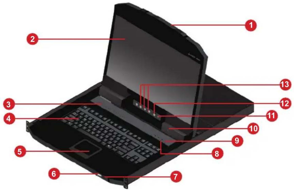
Labeled diagram of a laptop with numbered parts for identificationGCS1916W Front View

text_image
Labeled diagram of a laptop with numbered parts for identification| No. | Component Description | |
| 1 | Upper Handle with Release Bar | Pull to slide the LCD module outPush to slide the LCD module back in |
| 2 | LCD Module After sliding | the LCD module out, push the release bar on top of the handle to flip up the cover, accessing the LCD display |
| 3 | Port Selection Pushbutton / LEDs 8 for GCL1908W 16 for GCL1916W | Press the port pushbuttons to bring the KVM focus to the computer connected to the corresponding portAn Orange ON LINE LED lights up to indicate that the computer connected to its corresponding port is up and runningA Green SELECTED LED lights up to indicate that the computer connected to the corresponding port is selected for KVM control |
| 4 | Keyboard Standard 99-key keyboard | |
| 5 | Touchpad Standard mouse touchpad | |
| 6 | External Mouse Port | The USB port is available to connect a USB keyboard or mouse device for users who prefer to use external keyboard or mouse |
| 7 | Power LED | Lights green to indicate that the unit is receiving power |
| 8 | Lock LEDs The Num Lock | Caps Lock, Scroll Lock LEDs are located here |
| 9 | Reset Switch Located to | the right of the Lock LEDs.Press this recessed switch in with a small object to perform a system reset |
| 10 | Firmware Upgrade Port | The firmware upgrade cable will be connected to this 3.5mm audio jack to perform Firmware Upgrade |
| 11 | Firmware Upgrade Switch | During normal operation and while performing a firmware upgrade, this switch should be in NORMAL position.If a firmware upgrade operation does not complete successfully, this switch will be used to perform a firmware upgrade recovery.See Firmware Upgrade Recovery for details |
| 12 | LCD On/Off Button | Push this button to turn the LCD monitor on and off. The button lights up when the LCD monitor is offNote: This button lights up to indicate that the monitor is off, not the KVM switch |
| 13 | LCD Controls The buttons | to control the position and picture settings of the LCD display are located here |
GCS1908W Rear View

text_image
1 2 3 4 (GUL 5000) Power 8 7 6 5 4 3 2 1 (FL2-HM) ECGGCS1916W Rear View
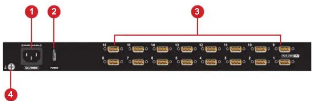
text_image
1 2 3 4 GCL 10000 16 15 14 13 12 11 10 9 8 7 6 5 4 3 2 1| No. | Component Description |
| 1 | Power Socket This is a standard 3-prong AC power socket. Connect power cord from an AC source to this socket |
| 2 | Power Switch This is a standard rocker switch that powers the GCL1908W/GCL1916W On and Off |
| 3 | KVM Port Section Connect the KVM cables to this portNote: the shape of these SPHD connectors have been specifically modified so that only KVM cables designed to work with this switch can be connected (see Cables for details)Do not attempt to use ordinary 15-pin VGA connector cables to link these ports to the computers. |
| 4 | Grounding TerminalConnect the grounding wire (used to ground the unit) into this port |
Before Installing
Please read Safety Instructions before proceeding with installation
The GCL1908W/GCL1916W is designed to work with USB and PS/2 interfaces. The LCD KVM Switch utilizes custom KVM cables that serve as intermediaries between the switch and the computers. A custom KVM cable is required for each computer. Please contact your dealer to find which custom KVM cables best fit your needs.
Please make sure that all devices including the GCL1908W/GCL1916W are powered OFF. Power cords of any computers that have the Keyboard Power On function must be unplugged.
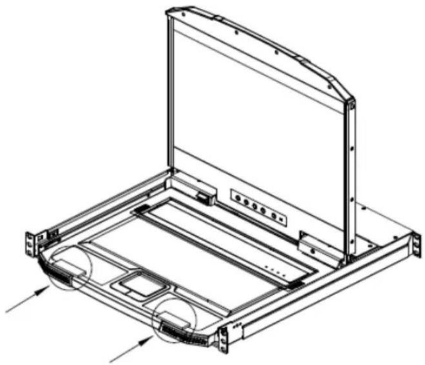
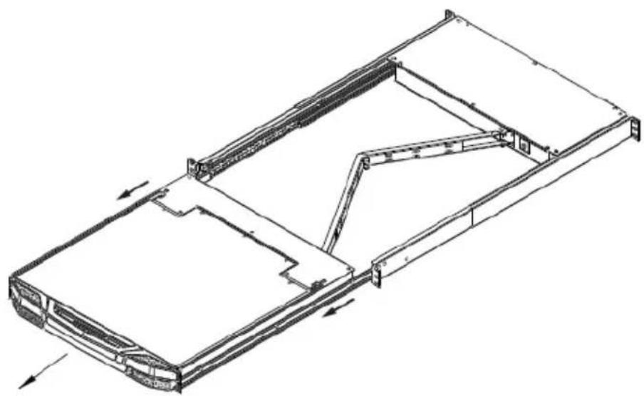
Packing material may be inserted from factory to protect GCL1908W/GCL1916W during shipping. Slide the LCD module out (see Opening / Closing the Console) until packing material is visible. Remove the packing material before installing the unit, as shown in diagram below
natural_image
Technical line drawing of a mechanical assembly with no visible text or symbolsThe GCL1908W/GCL1916W is designed for rack mounting. If the GCL1908W/GCL1916W is not rack mounted, please make sure to place it on a completely flat and firm surface before pulling the device in or out, preventing damage due to uneven force on the module

text_image
Place on Flat Surface × ○Standard Rack Mounting
Please use the included standard rack mounting kit to mount the GCL1908W/GCL1916W in a rack with a depth of 16.5" - 28.3"

text_image
I Bracket I BracketNote:
- We highly recommend two people to mount the module: one to hold it in place and the other person to screw the module in
- The included standard rack mounting kit does not include screws or cage nuts. Please contact your sales representative for additional screws or cage nuts
Please follow below steps to rack mount the GCL1908W/GCL1916W
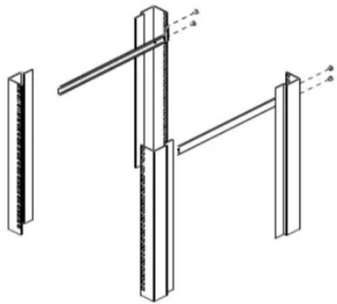
- Attach the left and right mounting brackets to the back of the rack, installing four screws into the tabs to secure the brackets in place
natural_image
Technical line drawing of a structural frame assembly with vertical supports and diagonal braces (no text or symbols)- While one person inserts the GCL1908W/GCL1916W into place by sliding its left and right side bars into the mounting brackets (on the rack), have the second person install four screws in the front tabs to secure the module to the front of the rack.

natural_image
Technical line drawing of a mechanical assembly with mounting brackets and internal components (no text or symbols)Note:
Please allow at least 2" on each side for proper ventilation and at least 5" at the back for the power cord and cable clearance
Grounding
To prevent damage to your installation, it is important that all devices be properly grounded. Use the included grounding wire to ground the GCL1908W/GCL1916W by connecting one end of the wire to the grounding terminal and the other end of the wire to a suitable grounded object

natural_image
Front view of a server rack with multiple ports and an AC power outlet, no visible text or labelsSingle Level Installation
In a single level installation, there are no additional switches cascaded from the first unit. To set up a single level installation, please follow below procedure
- Ground the GCL1908W/GCL1916W and make sure that the power has been turned off, including all computers that will be connected in this setup
- Use the included KVM cable sets (or the ones listed on under requirement) to connect any available KVM port to the keyboard, video and mouse ports on the computers being installed. Refer to KVM Cable Installation Diagrams on the following page
- Connect the power cable to an AC power source
- Turn the power to LCD console on
- Turn the power to the computers on
Single Level Installation Diagram

text_image
Diagram of a network switch or server rack with labeled ports and connectors, showing port numbers 1 through 5.Cable Connection Diagrams
KVM Cable Installation Diagrams
USB KVM Cable Connection

natural_image
Diagram of a computer tower connected to two cables, showing ports and connectors (no text or labels)PS/2 KVM Cable Connection

natural_image
Diagram of a server rack connected to three connected cables (no text or labels visible)Two Level Installation
To control even more computers, up to 8/16 additional switches can be cascaded from the first GCL1908W/GCL1916W. As many as 128 (GCL1908W) or 256 (GCL1916W) computers can be controlled form a single console in a complete cascade installation. Tables showing the relation between the number of computers and the number of switches needed to control them are provided in the Appendix
To set up a two level installation, please follow below procedure:
- Ground the master GCL1908W/GCL1916W and make sure that the power has been turned off to all computers that will be part of the installation.
- Using the included KVM cable, connect any available KVM port on the first level switch to the Console port on the second level unit
- Using a different KVM cable set (as listed under requirement), connect any available KVM port on the GCL1908W/GCL1916W installation to the keyboard, video, mouse ports of the computers being installed
- Repeat above steps for any additional units that will be added to the installation
- The Power On sequence requires that all slave units be powered on first. After they are powered on, the master unit must be powered on next. Only after all of the switches have been powered on in this sequence can the computers be powered on.
Note: The GCL1908W/GCL1916W can only be installed as the first switch in a two level installation as its LCD, keyboard and mouse are used as the console and all second level switches require an external console port to be cascaded
Two Level Installation Diagram
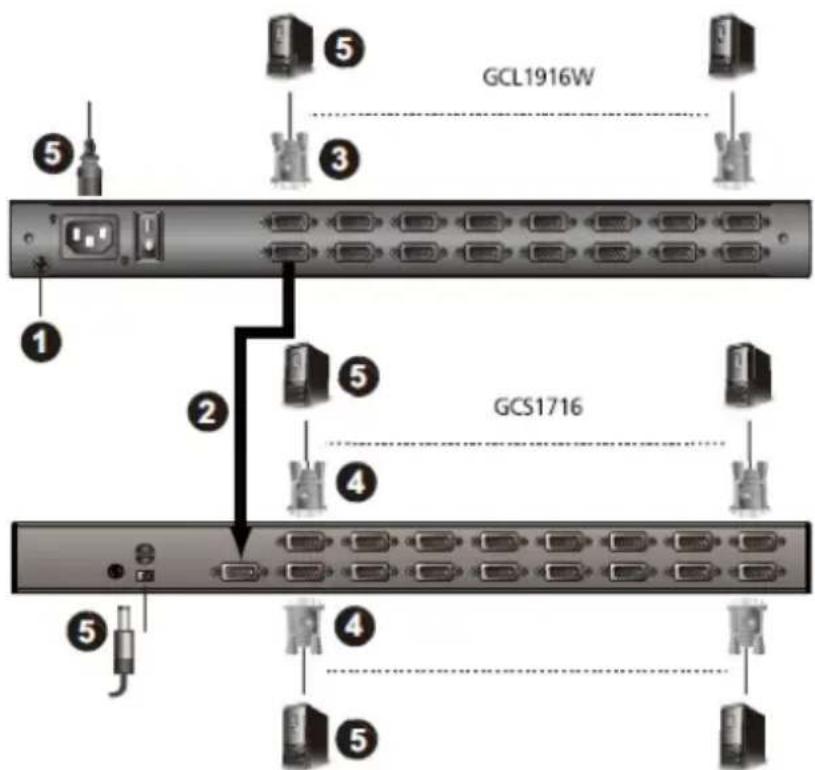
text_image
GCL1916W GCS1716Operation
Basic Operation
The GCL1908W/GCL1916W's console is a single rail console: the LCD display module and the keyboard/touch pad module can only slide in/out together. Please refer to the diagram below to open or close the console
- Pull on the Release Bar on the upper handle.

natural_image
Technical line drawing of a server rack frame (no text or symbols)- Slide the console module out until it clicks in place
natural_image
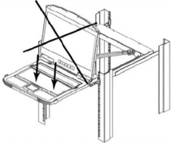
Technical line drawing of a mechanical assembly with internal components and directional arrows (no text or symbols)- Open the cover by pulling the Release Bar on the handle as pictured below

natural_image
Technical line drawings of a mechanical assembly with two views (top and side), showing internal components and mounting brackets (no text or symbols)- To close the console, lower the LCD Module until it lies flat, then slide the entire console in.

natural_image
Technical line drawing of a mechanical assembly with no visible text or symbolsOperating Precautions

The maximum load bearing capacity of the keyboard module is 66lb. Failure to heed below information can result in damage to the keyboard module.
| Right!Rest your hands and arms lightly on the keyboard module as you work. | |
 | |
 | Wrong!DO NOT lean your body weight on the keyboard moduleDO NOT place heavy objects on the keyboard module. |
LCD OSD Configuration
LCD Buttons
The LCD OSD allows you to set up and configure the LCD display. Four buttons are used to perform the configuration as described in the table below
| Button Function | |
| MENU Press this button to | invoke the Menu function and brings upthe Main Menu, if you have not already entered the LCD OSD Menu functionPress this button to bring up adjustment screen, if you have already entered the LCD OSD Menu function and reached a setting choice with the navigation buttons |
| ▶|▲ | When navigating through the menus, this button moves youRight or Up. When making an adjustment, it increases the value |
| ◀|▼ | When navigating through the menus, this button moves you Left or Down. When making an adjustment, it decreases the value |
| EXIT Press this button to | perform an auto adjustment, if you havenot already entered the LCD OSD Menu function. An auto adjustment automatically configures all the settings for the LCD panel to what the OSD considers their optimum values to bePress this button to exit the current menu and return to the previous menu, if you have already entered the LCD OSD Menu function. Us this button to leave an adjustment menu when you are satisfied with the adjustment madePress this button to exist the LCD OSD, if you are already at the Main Menu |
| PANEL POWER Press th | s button to turn the LCD monitor on and off. The button lights up when the LCD monitor is off.Note: The button lights up only indicating that the monitor off, not indicating the connected KVM switch |
LCD Adjustment Settings
An explanation of the LED OSD adjustment settings is given the below table
| Setting Explanation | |
| Brightness Adjusts the background black level of the screen image | |
| Contrast Adjusts the foreground white level of the screen image | |
| Phase If the pixel jitters or horizontal line noise is visible on the display, the LED may have the wrong phase setting. Adjust the phase setting to eliminate these problems | |
| Clock If a vertical banding is visible on the display, the LED may have the wrong clock setting. Adjust the clock setting to eliminate vertical banding | |
| H-Position Positions the display area on the LED panel horizontally (moves the display area left or right) | |
| V-Position Positions the display area on the LED panel vertically (moves the display area up or down) | |
| Color Temperature Adjusts the color quality of the display. You can adjust the warmth value, color balance, etc. The Adjust Color selection has a further submenu that lets you fine tune the RGB values. | |
| Language Selects the language that the OSD displays its menu in | |
| OSD Duration Lets you set the amount of time the OSD displays on the screen. If there is no input for the amount of time you choose, the OSD display turns off | |
| Reset Resets the adjustments on all menus and submenus to their factory default settings. Note: The Language setting does not return to the factory default, but remains at the one already set to. | |
Powering Off and Restarting
If it becomes necessary to Power Off the GCL1908W/GCL1916W (to upgrade the firmware for example), please follow below procedure
- Shut down all connected computers
Note: Unplug the power cords of all connected computers that have the Keyboard Power On function. Otherwise the GCL1908W/GCL1916W will still receive power from the computers
- Disconnect the GCL1908W/GCL1916W from its power source
- Wait 10 seconds, then connected the GCL1908W/GCL1916W power back in
- Turn the rear panel power switch back on
- After the GCL1908W/GCL1916W has started and recognize its station ID, turn all connected computers on
Note: If you need to shut down more than one station, power up the highest station first and work your way down to the lowest one
Hot Plugging
The GCL1908W/GCL1916W supports hot plugging – components can be removed and added to the console by unplugging their KVM cables from the ports without the need to shut the GCL1908W/GCL1916W down. In order for hot plugging to work properly, please follow below procedures:
Hot Plugging KVM Ports
In order for the OSD menus to correspond to the KVM port changes, you must manually reconfigure the OSD to reflect the new port information
Note: If the computer's OS does not support hot plugging, then this function may not work properly
Port Selection
The GCL1908W/GCL1916W provides 3 port selection methods to access the connected computers:
a. Manual
- Use the Port LED/Port pushbuttons located on the keyboard module to switch KVM focus to any port on the installation
b. On Screen Display (OSD) see OSD Operation
c. Hotkeys see Keyboard Port Operation
Port ID Numbering
Each port on a GCL1908W/GCL1916W installation is assigned a unique Port ID. You can directly access any computer on any level of the installation by specifying the Port ID that the computer is connected to – either via OSD (See OSD Operation) or with Hotkey port selection method (See Keyboard Port Operation)
- A computer connected to a master unit has a two digit Port ID (from 01-08 for the GCL1908W; from 01-16 for the GCL1916W) that corresponds to the KVM port number it is connected to
- A computer attached to a slave unit has a four digit Port ID. The first two digits represent the KVM port number on the slave unit that the computer is connected to. For example, a Port ID of 02-16 would refer to a computer that is connected to KVM port 16 of a slave unit that links back to KVM port 2 of the master unit.
OSD Overview
The On Screen Display (OSD) is a mouse and keyboard enabled – menu driven method to handle computer control and switching operations. All procedures start from the OSD main screen.
To go into OSD, press the OSD Hotkey twice
OSD Hotkey
The default hotkey is [Scroll Lock]. This hotkey can be changed to [Ctrl], please refer to Hotkey Summary Table for more information
OSD Login
The OSD incorporates a two level (administrator / user) password system. Before the OSD main screen displays, a login screen appears requiring a username and password.
If this is the first time you are using the OSD, or if the password function has not been set, simply press [Enter]. The OSD main screen will display under administrator mode. In this mode, you have administrator privileges, with access to all administrator and user functions, and can set up operations (including password authorization) if preferred.
It the password function has been set, you must provide an appropriate administrator / user password in order to access the OSD.
Manufacturing Number
The “MFG Number” (Manufacturing Number) is an internal serial number used by IOGEAR’s factory and technical support staff to identify products. This number does not affect product’s warranty. If your product requires after-sales services, you may provide the MFG Number to IOGEAR’s sales to technical support staff to identify the product and model number.
OSD Main Screen
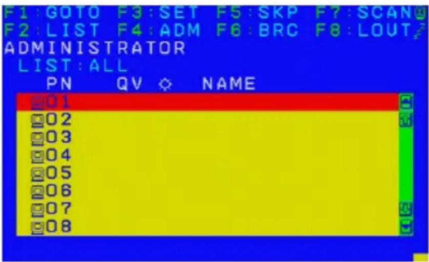
When OSD is invoked, below OSD screen will appear
text_image
F1: GOTO F3: SET F5: SKP F7: SCAN F2: LIST F4: ADM F6: BRC F8: LOUT ADMINISTRATOR LIST: ALL PN QV NAME 01 02 03 04 05 06 07 08Note:
The diagram depicts the administrator's main screen. The user main screen does not show the F4 (ADM) and F6 (BRC) functions, since these functions are reserved for the administrator and cannot be accessed by users
The OSD always starts in list view, with the highlight bar at the same position last time it was closed
Only the ports that have been set accessible by the administrator for the current logged-in user are visible (see Set Accessible Ports)
If the port list is collapsed, click on a switch number, or move the highlight bar to it, then press the right arrow key to expand the list. Similarly, to collapse a switch's port list, click on the switch number or move the highlight bar to it, then press the left arrow key to collapse the list
OSD Main Screen Headings
| PN This column lists | the port ID numbers for all the KVM ports on the installation.The simplest method to access a particular computer is to move the highlight bar to it, then press [Enter] |
| QV | If a port has been selected for quick view scanning (see Set Quick View Ports), an arrowhead displays in this column |
 | The computers that are powered on and are online have a sun symbol in this column |
| NAME If a port has been given a name (see Edit Port Names), its name appears in this column | |
OSD Navigation
- To dismiss the menu and deactivate OSD, click the X on the upper right corner of the OSD window, or press [Esc]
- To log out, click F8 at the top of the main screen or press [F8]
- To move up or down through the list one line at a time, click the Up and Down Triangle symbols ( ▲▼ ) or use the Up and Down arrow keys. If there are more list entries than what appears on the main screen, then the screen will scroll
- To move up or down through the list one screen at a time, click the Up and Down Arrow symbols (↑↓) or use the [Pg Up] and [Pg Dn] keys. If there are more list entries than what appears on the main screen, then the screen will scroll
- To activate a port, double-click it or move the highlight bar to the selected port then press [Enter]
• After executing any action, you will automatically go back to the menu one level above
OSD Functions
OSD functions are used to configure and control the OSD. For example, you can rapidly switch to any port, scan selected ports, limit the list you wish to view, designate a port as a quick view port, create or edit a port name or make OSD setting adjustments.
To access an OSD function:
Either click a function key field at the top of the main screen, or press a function key on the keyboard
In the submenus that appear, make your choice either by double-clicking it or by moving the highlight bar to the selection, then press [Enter]
Press [Esc] to return to the previous menu level
F1: GOTO
Clicking the F1 field or pressing [F1] activates the GOTO function. GOTO allows you to switch directly to a port either by keying in the Port Name or Port ID
To use the Port Name method, key in 1, key in Port Name, then press [Enter]
To use the Port ID method, key in 2, key in Port ID, then press [Enter]
Note: You can key in a partial name or port ID. In that case, the screen will show all of the connected computers that the user has View rights to (see Set Accessible Ports) that match the name or port ID pattern, regardless of the current list settings (see F2 LIST for details)
To return to the OSD main screen without making a choice, press [Esc]
F2: LIST
This function enables user to broaden or narrow the scope of which ports the OSD will display on the main screen. The submenu choices and their meanings are given in below table.
| Choice Meaning | |
| ALL Lists all of the ports on the installation that have been set accessible by the administrator for the current logged in user | |
| QUICK VIEW Lists only the ports that have been selected as quick view ports (see Set Quick View Ports) | |
| POWERED ON Lists only the ports that have their attached computers powered on | |
| QUICK VIEW + POWERED ON | Lists only the ports that have been selected as quick view ports (see Set Quick View Ports) and that have their connected computers powered on |
Move the highlight bar to the choice you want then press [Enter]. An icon appears before the choice to indicate that it is the currently selected one.
To exit LIST mode, press [Esc]
F3: SET
This function allows the administrator and each user to set up his own working environment. A separate profile for each is stored by the OSD and is activated according to the username that was provided during login.
To change a setting:
Double click or move the highlight bar to [F3] then press [Enter]
After an item is selected, a submenu with further choices appears. To make a selection, either double-click or move the highlight bar to the selection then press [Enter]. An icon appears before the selected choice to indicate which one it is. The settings are explained in the following table
| Setting Function | |
| OSD HOTKEY Selects which | hotkey activates the OSD function:[Scroll Lock][Scroll Lock] or [Ctrl][Ctrl]Since the [Ctrl] key combination may conflict with programs running on the computers, default OSD hotkey will be [Scroll Lock] combination |
| PORT ID DISPLAY POSITION | Allows each user to customize the position where the port ID appears on the screen. The default is the upper left corner, but users can choose to have it appear anywhere on the screen.Use the mouse or the arrow keys plus Pg Up, Pg Dn, Home, End, and 5 (on the numeric keypad with Num Lock off), to position the port ID display, then double-click or press [Enter] to lock the position and return to the Set submenu |
| PORT ID DISPLAY DURATION | Determines how long a port ID displays on the monitor after a port change has taken place. The choices are:3Seconds(default) and Always Off |
| PORT ID DISPLAY MODE | Selects how the port ID is displayed: the port number plus the port name (PORT NUMBER + PORT NAME) (default); the port number alone (PORT NUMBER); or the port name alone (PORT NAME) |
| SCAN DURATION Determining | es how long the focus dwells on each port as it cycles through the selected ports in the Auto Scan Mode (seeF7 SCAN)Key in a value from 1 – 255 seconds, then press[Enter]Default is 5 seconds; a setting of 0 disables the SCAN function |
| SCAN-SKIP MODE Selects | which computers will be accessed under skip mode (seeF5 SKP) and Auto Scan Mode (seeF7 Scan)Choices:ALL – All ports which have been set accessible (see Set Accessible Ports)QUICK VIEW – Only those ports which have been set accessible and have been selected as quick view ports (see Set Quick View Ports)POWERED ON – Only those ports which have been set accessible and are powered onQUICK VIEW + POWERED ON – Only those ports which have been set accessible and have been selected as quick view port and are powered on.The default is ALLNote: The quick view choices only show up on the administrator's screen, since only admin has Quick View setting rights (seeSet Quick View Ports) |
| SCREEN BLANKER If there | is no input from the console for the amount of time set with this function, the screen turns blank.Key in a value from 1 – 30 minutes then press[Enter]The default setting of 0 disables this function |
| HOTKEY COMMAND MODE | Enables/disables the hotkey command function in case a conflict with programs running on the computers occurs |
| HOTKEY Sets the keyboard | shortcut for invoking Hotkey ModeThe default:[Num Lock]+[-]Or another option is[Ctrl]+[F12] |
| OSD LANGUAGE Sets the language | language used in the OSDEnglish (default), German, Japanese, Simplified Chinese or Traditional Chinese |
| TOUCHPAD Enables/disables | les the touchpad function |
To exit SET mode, press [Esc]
F4: ADM
F4 is an administrator only function. This function allows the administrator to configure and control the overall operation of the OSD. To change a setting, double-click F4 or use the Up and Down Arrow keys to move the highlight bar to F4 then press [Enter]
After an item is selected, a submenu with further choices to select from appears. Double-click an item or move the highlight bar to the selection then press [Enter]. An icon appears before the selected item so that you know which one is being selected. The settings are explained in the following table
| Setting Function | |
| SET USER LOGIN This function is used to set usernames and passwords for the administrator and users:Usernames and passwords for one administrator and four users can be setAfter you select the administrator field or one of the user fields, a screen that allows you to key in the username and password appears. Usernames and passwords can be from 1 to 16 characters long and can consist of any combination of letters and number (A-Z, 9-0) and some additional keys (* () + : - , ? . / space)For each individual, key in the username and password, confirm the password, then press [Enter]To modify or delete a previous username and/or password, use the backspace key to erase individual letters or numbers. Press [Enter] when doneNote:Usernames and passwords are not case sensitive. Usernames are displayed in capital letters in the OSZ | |
| SET ACCESSIBLE PORTS This function allows the administrator to define user access to the computers on the installation on a port-by-port basis.For each user, select the target port, then press the [Spacebar] to cycle through the choices:F (full access)V (view only)Or blank.Repeat until all access rights have been set then press [Enter]The default is FF for all users on all portsNote:A blank setting means that no access rights are granted. The port will not show up on the user's LIST on the main screenThe administrator always has full access to all ports | |
| SET LOGOUT TIMEOUT If there is no input from the console for the amount of time set with this function, then the user is automatically logged out. A login is necessary before the console can be used again.This enables other users to gain access to the computers when the original user is no longer accessing them but has forgotten to log out.To set the timeout value, key in a number from 1 – 180 minutes, then press [Enter]The default setting of 0 disables this functionNote: This feature does not function if Set Login Mode is disabled, see SET LOGIN MODE | |
| EDIT PORT NAMES To help remember which computer is attached to a particular port,every port can be given a name. This function allows the administrator to create, modify or delete port namesTo edit a port name:Click the port or use the navigation keys to move the highlight bar to it,then press [Enter]Key in the new port name, or modify/delete the old one. The maximum number of characters allowed for the port name is 12.Legal characters include:All alpha characters: A – ZAll numeric characters: 0 – 9*( ) + : - , ? . / spaceCase does not matter, the OSD displays the port name in all capitals no matter how they were keyed inWhen you have finished editing, press [Enter] to have the change take effect. To abort the change, press [Esc] | |
| RESTORE DEFAULT VALUES | This function is used to undo all changes and return the setup to the original factory default settings (see OSD FACTORY DEFAULT SETTINGS) except for the port name list, username and password information, which are saved |
| CLEAR THE NAME LIST This function clears the port name list | |
| ACTIVATE BEEPER | Choices are Y (on) or N (off)When activated, the beeper sounds whenever a port is changedWhen activating the Auto Scan function (see F7 SCAN) or an invalid entry made on an OSD menu.The default is Y |
| SET QUICK VIEW PORTS This function lets the administrator select which ports to include as quick view ports:To select/deselect a port as a quick view port, double-click the port or use the navigation keys to move the highlight bar to the port then press [Spacebar]When a port has been selected as a quick view port, an icon display in the QV column of the LIST on the main screen. When a port is deselected, the icon disappearsIf one of the quick view options is chosen for the LIST view (see F2 LIST) only a port that has been selected here will be displayed on the listIf one of the quick view options is chosen for auto-scanning (see SCAN/SKIP MODE) only a port that has been selected here will be auto-scanned.The default has no ports selected for quick view |
| SET OPERATING SYSTEM This function allows the administrator to define the operating system for the computer connected to each KVM port. The default is WIN (PC compatible)To set the port operating system:From the list, select the port for which you wish to set the computer's operating systemSet the operating system by pressing [Spacebar] to cycle through WIN, MAC, SUN or OTHERPress [Esc] to exit. The operating system you selected assigned to the KVM port |
| FIRMWARE UPGRADE In order to upgrade the GCL1908W/GCL1916W firmware, you must first enable the Firmware Upgrade Mode with this settingWhen you bring up this menu, the current firmware versions levels are displayed. Select Y to enable Firmware Upgrade Mode or N to leave this menu without enabling it |
| SET KEYBOARD LANGUAGESets the language for the computer keyboard attached to the KVM portTo select a keyboard language, double-click it or use the navigation keys to move the highlight bar then press [Enter]Language Options: AUTO (default), ENGLISH (US), ENGLISH (UK), GERMAN (GER), GERMAN (SWISS), FRENCH, HUNGARIAN, ITALIAN, JAPANESE, KOREAN, RUSSIAN, SPANISH, SWEDISH, and TRADITIONAL CHINESE |
| SET LOGIN MODE This function allows the administrator to request users to login or not.When the login dialog box is disabled, the system disables the login/ logout function, If the system is restarted, the login/logout function remains disabled |
To exit ADM mode, press [Esc]
F5: SKP
Clicking the F5 field or pressing [F5] invokes SKIP (SKP) mode. This function enables you to easily skip backward or forward – switching the console focus from the currently active computer port to the previous or next available one
The Selection of computers to be available for skip mode switching is made with Scan-Skip mode setting under F3: SET function
When you are in skip mode
Press [←] to switch to the previous computer in the list
Press [→to switch to the next computer in the list
Note: when you skip, you only skip to the previous or next available computer that is in the Scan-Skip mode selection
If a port has been selected for Scan-Skip mode, when the focus switches to that port a left/right triangle symbol appears before it port ID display.
While skip mode is in effect, the console will not function normally. You must exit skip mode in order to regain control of the console
To exit skip mode, press [Spacebar] or [Esc]
F6: BRC
F6 is an administrator only function. Clicking the F6 field or pressing [F6] will invoke the Broadcast (BRC) mode. When this function is in effect, commands sent from the console are broadcast to all available computers on the installation.
This function is particularly useful for operations that need to be performed on multiple computers, such as performing a system wide shutdown, installing or upgrading software, etc.
While BRC mode is in effect, a speaker symbol appears before the port ID display of the port that currently has the console focus
While BRC mode is in effect, the mouse will not function normally. You must exit BRC mode in order to regain control of the mouse
To exit BRC mode, invoke the OSD with OSD hotkey then click the F6 field or press [F6] to turn BRC mode off and the speaker symbol will disappear
F7: AUTO SCAN
Clicking the F7 field or pressing [F7] invokes Auto Scan mode. This function allows you to automatically switch among the available computers at regular intervals so that you can monitor their activity without having to take the trouble of switching yourself.
The selection of computers to be included for auto-scanning is made with the Scan-Skip mode setting under the F3: SET function
The amount of time that each port displays for is set with the Scan Duration setting under the F3: SET function. When you want to sop at a particular location, press the [Spacebar] to stop scanning
If the scanning stops on an empty port or one where the computer is attached but powered Off, the monitor screen will be blank and the mouse and keyboard will have no effect. After the Scan Duration time is up, the scan function will move on to the next port
As each computer is accessed, an S appears in front of the port ID display to indicate that is being accessed under Auto Scan mode
While Auto Scan mode is in effect, the console will not function normally. You need to exit Auto Scan mode in order to regain control of the console
While you are in Auto Scan mode, you can paus the scanning in order to keep the focus on a particular computer either by pressing P or with a left-click of the mouse. See Invoking Auto Scan
To exit Auto Scan mode, press [Spacebar] or [Esc]
F8: LOGOUT
Clicking the F8 field or pressing [F8] will log you out of OSD control of the computers and blanks the console screen. This is different from simply pressing [Esc] when you are at the main screen to deactivate the OSD. With this function, you must log in all over again to regain access to the OSD, whereas with [Esc], all you have to do to reenter OSD is to tap the OSD hotkey
Note:
When you reenter the OSD after logging out, the screen stays blank except for the OSD main screen. You must input your username and password before you can continue
If you reenter the OSD after logging out and immediately use [Esc] to deactivate the OSD without having selected a port from the OSD menu, a null port message displays on the screen. The OSD hotkey will bring up the main OSD screen.
Hotkey Port Control
IOGEAR's GCL1908W/GCL1916W provides an extensive, easy-to-use, hotkey function for convenience in controlling and configuring KVM installation from the keyboard. The GCL1908W/GCL1916W provides the following hotkey port control features:
- Selecting the Active Port
• Auto Scan Mode Switching - Skip Mode Switching
• Computer Keyboard/Mouse Reset
The following settings can also be controlled in the Hotkey mode
- Setting the Beeper
- Setting the Quick Hotkey
- Setting the OSD Hotkey
- Setting the Port Operating System
- Restoring the OSD Default Values
Invoke Hotkey Mode
All hotkey operations begin by invoking Hotkey mode. Please make sure that the Hotkey Command Mode function is enabled and that you key in the appropriate Hotkey.
There are 2 possible keystroke sequences used to invoke Hotkey mode, though only one can be operational at any given time:
[Num Lock] + [-]
- Hold down [Num Lock]
- Press and release [-]
- Release [Num Lock]
[Ctrl] + [F12]
- Hold down [Ctrl]
- Press and release [F12]
- Release [Ctrl]
When Hotkey mode is active:
- A command line appears on the monitor screen. The command line prompt is the word Hotkey: in white text on a blue background and displays the subsequent hotkey information that you key in
- Ordinary keyboard and mouse functions are suspended – only hotkey compliant keystrokes (described in the following section) can be entered.
Press [Esc] to exit Hotkey mode
Select the Active Port
Each KVM port is assigned a port ID (see Port ID Numbering). You can directly access any computer on the installation with a hotkey combination that specifies the port ID of the KVM port that a computer is connected to. To access a computer using hotkeys:
- Invoke hotkey mode with [Num Lock] + [-] or [Ctrl] + [F12] combination
- Key in the port ID
The port ID numbers display on the command line as you key them in. If you make a mistake, use [Backspace] to erase the wrong number
- Press [Enter]
After you press [Enter], the KVM focus switches to the designated computer and you automatically exit hotkey mode
Note: In the hotkey mode, KVM focus will not switch to a port if an invalid switch or port number is entered. The hotkey command line will continue to display on the screen until you enter a valid switch and port number combination or exit hotkey mode.
Auto Scan Mode
Auto Scan automatically switches, at regular intervals, among all the KVM ports that have been set as accessible under Scan-Skip Mode, so that their activity can be monitored automatically. See Scan-Skip Mode for more information.
Invoking Auto Scan
To start Auto Scan, key in the following Hotkey combination:
- Invoke hotkey mode with the [Num Lock] + [-] or [Ctrl] + [F12] combination
- Press [A] then [Enter], then you will automatically exit hotkey mode and enter Auto Scan mode
- While you are in Auto Scan mode, you can pause the scanning in order to keep the focus on a particular computer either by pressing P or with a left-click of the mouse. During the time that auto-scanning is paused, the command line displays:
Auto Scan: Paused
Pausing when you want to keep the focus on a particular computer is more convenient than exiting Auto Scan because when you resume scanning, you start from where you left off. If, on the other hand, you exited and restarted, scanning would start over from the very first computer on the installation.
To resume Auto Scanning, press any key or left-click. Scanning continues from where it left off
- While Auto Scan mode is in effect, ordinary keyboard and mouse functions are suspended – only Auto Scan mode compliant keystrokes and mouse clicks can be entered. You must exit Auto Scan mode in order to regain normal control of the console.
Note: Auto Scan duration could be adjusted via OSD menu
- To exit Auto Scan mode press [Esc] or [Spacebar]. Auto-scanning stops when you exit Auto Scan mode.
Skip Mode
This feature allows you to switch between computers in order to monitor them manually. You can dwell on a particular port for as long as you like – as opposed to auto-scanning, which automatically switches after a fixed interval.
To invoke Skip mode, key in the following hotkey combination:
- Invoke hotkey mode with the [Num Lock] + [-] or [Ctrl] + [F12] combination
- Key in [Arrow]
- Where [Arrow] refers to one of the arrow keys. After you press an arrow, you automatically exit hotkey mode and enter Skip mode where you can switch ports as follows:
| ← | Skips to the first accessible port. See Scan/Skip Mode for more details |
| → | Skips to the next accessible port |
- Once you are in Skip mode, you can keep on skipping by pressing the arrow keys. You do not have to use [Num Lock] + [-] combination again
-
While Skip mode is in effect, ordinary keyboard and mouse functions are suspended – only Skip mode compliant keystrokes can be entered. You must exit Skip mode in order to regain normal control of the console.
-
To exit Skip mode, press [Esc] or [Spacebar]
Computer Keyboard / Mouse Reset
If the keyboard or mouse cease to function on the computer connected to the currently selected port, you can perform a keyboard / mouse reset on the computer. This function is essentially the same as unplugging and re-plugging the keyboard and mouse on the target computer. To perform a computer keyboard/mouse reset, key in the following hotkey combination:
- Invoke hotkey mode with the [Num Lock] + [-] or [Ctrl] + [F12]
- Press [F5]
After you press [F5], you will automatically exit Hotkey mode and regain keyboard and mouse control on the computer connected to the KVM port. If you fail to regain keyboard/mouse control on the computer after pressing [F5], perform a console keyboard and mouse reset. See Port Selection Pushbutton / LEDs for more detailed information.
Hotkey Beeper Control
The beeper is a hotkey that can be toggled on and off. To toggle the beeper, key in the following hotkey combination:
- Invoke hotkey mode with the [Num Lock] + [-] or [Ctrl] + [F12] combination
- Press [B]
After you press [B], the beeper toggles on or off. The command line displays Beeper On or Beeper Off for one second, then the message disappears and you automatically exit hotkey mode.
Quick Hotkey Control
The Quick Hotkey can be toggled between [Num Lock] + [-] or [Ctrl] + [F12] combination. To toggle the Quick Hotkey:
- Invoke hotkey mode with the [Num Lock] + [-] or [Ctrl] + [F12] combination
- Press [H]
After you press [H], the command line displays HOTKEY HAS BEEN CHANGED for one second then the message disappears and you automatically exit Hotkey mode
OSD Hotkey Control
The OSD Hotkey can be toggled between [Scroll Lock] [Scroll Lock], [Ctrl][Ctrl], or [Alt][Alt]. To toggle the OSD Hotkey, key in the following hotkey combination:
- Invoke hotkey mode with the [Num Lock] + [-] or [Ctrl] + [F12] combination
- Press [T]
After you press [T], the command line displays HOTKEY HAS BEEN CHANGED for one second then the message disappears and you automatically exit Hotkey mode.
Port OS Control
A port's operating system can be changed to match that of the computer attached to the port. To change a port's operating system, key in the following hotkey combination:
- Invoke hotkey mode with the [Num Lock] + [-] or [Ctrl] + [F12] combination
- Key in [Function], where [Function] refers to one of the function keys in the following table
| Key Description | |
| F1 Sets the Port OS to Windows | |
| F2 Sets the Port OS to Mac | |
| F3 Sets the Port OS to Sun | |
After pressing a function key, you automatically exit Hotkey mode
Set USB Speed
Users can use hotkeys to set the USB speed of the selected KVM port to low or full sped to comply with the connected computers
- Invoke hotkey mode with the [Num Lock] + [-] or [Ctrl] + [F12] combination
- Press [F11]
- Key in [Function], where [Function] refers to one of the function keys in the following table:
| Key Description | |
| L Set the KVM port to low | speed USB |
| F Set the KVM port to full | speed USB |
4. Press [Enter]
To set all KVM ports of the selected KVM station, add an [A] after the function key: Under Hotkey mode, press [F11][L][A][Enter] or [F11][F][A][Enter]
Restore Default Values
This administrator only hotkey restores the GCL1908W/GCL1916W default values. See Restore Default Values for more detailed information. To restore the default values, key in the following hotkey combination:
- Invoke hotkey mode with the [Num Lock] + [-] or [Ctrl] + [F12] combination
- Press [R]
- Press [Enter]
After you press [Enter], the command line displays RESET TO DEFAULT SETTING for three seconds, then the message disappears and you automatically exit Hotkey mode
Hotkey Summary Table
| Invoke HSM Hotkey Action | ||
| [Scroll] + [Scroll] | [Scroll Lock] | Activate OSD modeClick [Esc] to close the OSD and go back to the normal PC operation |
| [Scroll Lock] | ||
| [Num Lock] + [-]Or[Ctrl] + [F12] | [A] / [a] [Enter] Invokes | Auto Scan mode. The KVM focus cycles from port to port at 5-second intervalsAuto Scan duration could be adjusted via OSD menuWhen Auto Scan mode is in effect [P] or left-click pauses auto-scanning.When auto-scanning is paused, pressing any key or another left-click resumes auto-scanning |
| [Port ID][Enter] Switches access to the computer that corresponds to that Port ID (GCL1908W: 01 - 08; GCL1916W: 01 -16) | ||
| [B] Toggles the beeper on or off (Default Setting is on) | ||
| [Esc] or [Spacebar] Exists hotkey mode or to quit the Setting Mode | ||
| [F1] Set Windows keyboard emulation (Default Setting) | ||
| [F2] Set Mac keyboard emulation | ||
| [F3] Set Sun keyboard emulation | ||
| [F5] Performs a keyboard / mouse reset on the target computer | ||
| [H] / [h] Toggles the Quick Hotkey invocation keys between [Ctrl] + [F12] and [Num Lock] + [-] | ||
| [R] / [r] [Enter] This administrator only hotkey restores the switch's default values. See Restore Default Values | ||
| [F11] [F] [Enter] Set the selected KVM port to full speed USB | ||
| [F11] [L] [Enter] Set the selected KVM port to low speed USB | ||
| [F11] [F][A] [Enter] Set the selected KVM station to full speed USB | ||
| [F11] [L] [A] [Enter] Set the selected KVM station to low speed USB | ||
| [T] / [t] Toggles the OSD Hotkey between [Ctrl][Ctrl] and [Scroll Lock][Scroll Lock] | ||
| [←] | Invokes Skip mode and skips from the current port to the first accessible port previous to it | |
| [→] | Invokes Skip mode and skips from the current port to the next accessible port | |
Keyboard Emulation
Mac Keyboard Emulation
The PC compatible (101/104 key) keyboard can emulate the functions of Mac keyboard. The emulation mapping are listed in table below
| PC Keyboard Mac Keyboard | |
| [Shift] Shift | |
| [Ctrl] Ctrl | |
 |  |
| [Ctrl][1] |  |
| [Ctrl][2] |  |
| [Ctrl][3] | [Y6BY] |
| [Ctrl][4] |  |
| [Alt] Alt | |
| [Print Screen] F13 | |
| [Scroll Lock] F14 | |
 | [IMAGE] |
| [Enter] Return | |
| [Backspace] Delete | |
| [Insert] Help | |
  |
Note: When using key combinations, press and release the first key [Ctrl], then press and release the activation key.
Sun Keyboard
The PC compatible (101/104 key) keyboard can emulate the functions of the Sun keyboard when the Control key [Ctrl] is used in conjunction with other keys. The corresponding functions are shown in the table below
| PC Keyboard Sun Keyboard | |
| [Ctrl] [T] Stop | |
| [Ctrl] [F2] Again | |
| [Ctrl] [F2] Props | |
| [Ctrl][F4] Undo | |
| [Ctrl][F5] Front | |
| [Ctrl][F6] Copy | |
| [Ctrl][F7] Open | |
| [Ctrl][F8] Paste | |
| [Ctrl][F9] Find | |
| [Ctrl][F10] Cut | |
| [Ctrl] [F1] |  |
| [Ctrl] [F2] - |  |
| [Ctrl] [F3] + |  |
| [Ctrl] [F4] | ### |
| [Ctrl] [H] Help | |
| ### | Compose |
| ### | ◆ |
Note: When using key combinations, press and release the first key [Ctrl], then press and release the activation key.
Firmware Upgrade Configuration
GCL1908W/GCL1916W Windows based Firmware Upgrade Utility (FWUpgrade.exe) provides a smooth-automated process for firmware upgrade.
The Utility comes as part of a Firmware Upgrade Package that is specific for each device. New firmware upgrade packages are posted on our IOGEAR.COM website, as new firmware revisions become available. Please check the website regularly to find latest packages and information relating to firmware revisions and upgrades.
Before Starting Firmware Upgrade
In order to better perform a firmware upgrade, using a computer that is not connected to the GCL1908W/GCL1916W setup is recommended. To set GCL1908W/GCL1916W to Firmware Upgrade Mode:
- From a computer that is not part of the KVM installation, go to www.iogear.com/product/GCL1908W or www.iogear.com/product/GCL1916W to get a list of available Firmware Upgrade Packages
- Choose the Firmware Upgrade Package (usually the most recent one), and download the file to a computer that is not part of the KVM installation
- Use the included Firmware Upgrade Cable to connect a COM port from your computer to the Firmware Upgrade Port of the GCL1908W/GCL1916W
text_image
Firmware Upgrade Utility Welcome to the Firmware Upgrade Utility. Put your device into Firmware Upgrade Mode. Use the Firmware Upgrade Cable to connect its Firmware Upgrade Port to your computer (or connect via Ethernet). Agree to the License Agreement: Then Click Next. LICENSE AGREEMENT LICENSE GRANT ATEN International Co., Ltd. ("Licensor") grants to you a non-exclusive, non-transferable license to access and use FIRMWARE UPGRADE UTILITY (the "Product") during the "Term" set forth below. You may install the Product on a hard disk or other storage device; install and use the Product on a file server for use on a network for the purposes of (i) permanent installation onto hard disks or other storage devices or (ii) use of the Product over such network; and make backup copies of the Product. RESTRICTIONS You agree not to modify, adapt, translate, reverse engineer, recompile, disassemble or otherwise attempt to discover the source code of the Product, or create derivative works based on the Product, or remove any proprietary notices or labels on the Product, including copyright, trademark or patent pending notices. You may not sublicense the Product or otherwise allow others to use the Product licensed to you. Help About < Back Next > Cancel- From your GCL1908W/GCL1816W console, login to the OSD as the administrator and select the F4 ADM function.
- Scroll down to FIRMWARE UPGRADE. Press [Enter], then press [Y] to invoke Firmware Upgrade mode
When the GCL1908W/GCL1916W is in Firmware Upgrade Mode, the Num Lock, Caps Lock and Scroll Lock LEDs will continuously flash on and off
To exit Firmware Upgrade Mode, see Firmware Upgrade Mode
Starting Firmware Upgrade
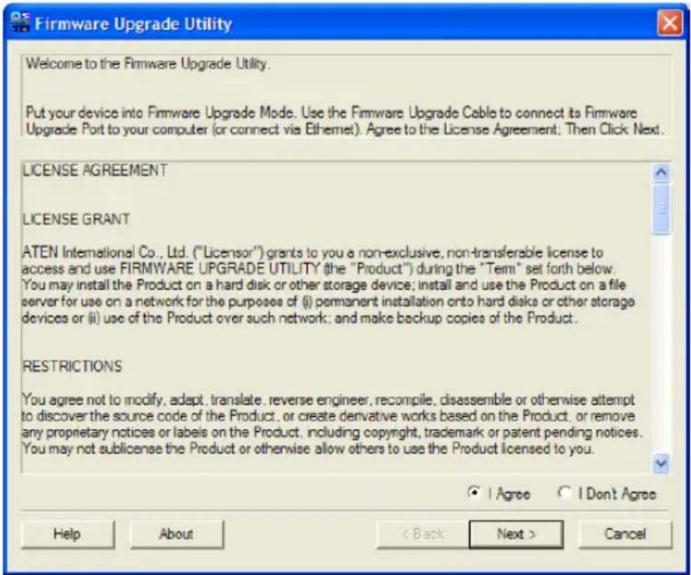
- With the GCL1908W/GCL1916W on Firmware Upgrade Mode, run the downloaded Firmware Upgrade Package file from your computer – either by double clicking the file icon or by opening a command line and keying the full path and filename

text_image
Firmware Upgrade Utility Welcome to the Firmware Upgrade Utility. Put your device into Firmware Upgrade Mode. Use the Firmware Upgrade Cable to connect its Firmware Upgrade Port to your computer (or connect via Ethernet). Agree to the License Agreement; Then Click Next. LICENSE AGREEMENT LICENSE GRANT ATEN International Co., Ltd. ("Licensor") grants to you a non-exclusive, non-transferable license to access and use FIRMWARE UPGRADE UTILITY (the "Product") during the "Term" set forth below. You may install the Product on a hard disk or other storage device; install and use the Product on a file server for use on a network for the purposes of (i) permanent installation onto hard disks or other storage devices or (ii) use of the Product over such network; and make backup copies of the Product. RESTRICTIONS You agree not to modify, adapt, translate, reverse engineer, recompile, disassemble or otherwise attempt to discover the source code of the Product, or create derivative works based on the Product, or remove any proprietary notices or labels on the Product, including copyright, trademark or patent pending notices. You may not sublicense the Product or otherwise allow others to use the Product licensed to you. ● I Agree ○ I Don't Agree Help About < Back Next > Cancel- Read and Agree to the License Agreement (enable the "I Agree" radio button)
- Click Next. The Firmware Upgrade Utility main screen appears

text_image
Firmware Upgrade Utility If Check Firmware Version is checked, the utility compares the device's firmware level with the upgrade files. If the device's version is newer, the utility lets you decide whether to continue or not. If it is not checked, the utility performs the upgrade directly. Click Next to begin. Device List: MAIN : 001-001 IO1 : 001-002 IO2 : 001-003 Status Messages: > Loading & testing files ... > Loading & testing files: OK > Searching for devices ... Device Description ✓ Check Firmware Version Progress... Help View Log < Back Next > CancelThe Utility inspects your installation. All devices capable of being upgraded by the package are listed under the Device List panel
- Click Next to perform the upgrade.
a. If the Check Firmware Version is enabled, the Utility compares the device's firmware level with that of the upgrade files. If it finds that the device's version is higher than the upgrade version, it brings up a dialog box informing you of the situation and gives the option to continue with the upgrade

text_image
Warning The firmware (Ver 1.0.086) is not newer than current firmware (Ver 1.0.086) in device IO1 : 001-002 Continue the upgrade? (Yes/No) Yes Nob. If Check Firmware Version is disabled, the Utility installs the upgrade files without checking whether they are at higher level or not
c. As the Upgrade proceeds, status messages appear in the Status Messages panel and the progress towards completion is shown on the Progress bar
Firmware Upgrade Succeeded
After the upgrade has completed, a screen appears to inform you that the procedure was successful

text_image
Firmware Upgrade Utility The Firmware upgrade was successful. Click Finish to close the utility. Device List: MAIN : 001-001 IO1 : 001-002 IO2 : 001-003 Status Messages: > Loading & testing files ... > Loading & testing files: OK > Searching for devices ... > Preparing firmware upgrade ... > Firmware version is not newer than device IO1 : 001-002 > Firmware version is not newer than device IO2 : 001-003 > Preparing firmware upgrade: OK > Upgrading device MAIN : 001-001 ... > Upgrading device MAIN : 001-001: OK > Upgrading device IO1 : 001-002 ... > Upgrading device IO1 : 001-002: OK > Upgrading device IO2 : 001-003 ... > Upgrading device IO2 : 001-003: OK > Firmware upgrade: OK Device Description Device F/W: Ver 1.0.086 Upgrade F/W: Ver 1.0.081 MID: 001-003 Check Firmware Version Progress... Help View Log Back Finish CancelClick Finish to close the Firmware Upgrade Utility
If the firmware upgrade fails, the Upgrade Succeeded screen will not appear.
Possible reasons for firmware upgrade failure are:
- When a firmware upgrade was manually aborted
- When the unit's firmware becomes corrupted for some reason and unable to be operated
- When a firmware upgrade procedure is interrupted
To recover a failed firmware upgrade, do the following:
- Power OFF the GCL1908W/GCL1916W
- Connect the Firmware Upgrade Cable to the Firmware Upgrade Port
- Slide the Firmware Upgrade Switch to the Recover position
- Power ON the GCL1908W/GCL1916W and repeat the Firmware Upgrade Procedure
- After the GCL1908W/GCL1916W has been successfully upgraded, power the KVM console OFF, and slide the Firmware Upgrade Switch back to the Normal position.
- Then, power the GCL1908W/GCL1916W back on again
Exiting the Firmware Upgrade Mode
To exit the Firmware Upgrade Mode, please do the following:
- Slide the Firmware Upgrade Recovery Switch to NORMAL position
- Turn the GCL1908W/GCL1916W power off and restart according to the instructions given in Powering Off and Restarting
| Function GCL1908W GCL19 | 16W | |
| Computer Connections | ||
| Direct 8 16 | ||
| Maximum thru Cascade 128 256 | ||
| Console Selection OSD, Hotkey, Pushbutton | ||
| Connectors | ||
| KVM Ports x SPHD Female (Yellow) 16 x SPHD Female (Yellow) | ||
| USB Port 1 x USB Type-A Female | ||
| Firmware Upgrade 1 x 3.5mm | Audio Jack Female (Black) | |
| Power 1 x 3-prong AC Socket | ||
| Switches | ||
| Reset 1 x Semi-recessed pushbutton | ||
| Firmware Upgrade 1 x Slide | ||
| Power 1 x Rocker | ||
| LCD Power | 1 x Pushbutton | |
| LCD Adjustment | 4 x Pushbutton | |
| Port Selection | 8 x Pushbutton | 16 x Pushbutton |
| LEDs | ||
| On Line | 8 (Orange) | 16 (Orange) |
| Selected | 8 (Green) | 16 (Green) |
| Power | 1 x KVM Console (Dark Green)1 x LCD (Orange) | |
| Lock | 1 x Num Lock (Green)1 x Caps Lock (Green)1 x Scroll Lock (Green) | |
| Emulation | ||
| Keyboard/Mouse | PS/2, USB | |
| Video | ||
| Input Video Resolution 1366 x 768 @60Hz | ||
| Panel Spec | ||
| LCD Module | 18.5" TFT-LCD | |
| Resolution | 1366 x 768 @60Hz | |
| Response Time | 5ms | |
| Viewing Angle | 170degree (H), 160degree (V) | |
| Contrast Ratio 700:1 | ||
| Pixel Pitch 0.3mm x 0.3mm | ||
| Support Color 16.7M colors | ||
| Luminance 200 cd/m2 | ||
| Scan Interval 1-255 seconds | ||
| Maximum Input Power Rating | 100-240 V AC, 50-60Hz, 1A | |
| Power Consumption AC | 110V:14.1W:70BTU | AC220V:14.9W:74BTU |
| Environmental | ||
| Operating Temperature 0-40 C | ||
| Storage Temperature -20-60 C | ||
| Humidity 0-80% RH Non-condensing | ||
| Physical Properties | ||
| Housing Metal + Plastic | ||
| Weight 23.1lb 23.32lb | ||
| Dimensions (L x W x H) 17.69" x 23" x 1.69" | ||
| Body Dimension (L x W x H) 18.92" x 24.87" x 1.69" | ||
Note
- For some rack mount products, please note that the standard physical dimensions of W x D x H are expressed using a L x W x D format
- Body Dimensions exclude I/O ports, handles and mounting brackets
Trouble Shooting
Troubleshooting
| Symptom Action | |
| Some characters entered from the keyboard do not display correctly | The keyboard layout setting for the port does not match the keyboard you are using. On your switch, please change the keyboard layout setting for the port to match the layout of the keyboard you are using |
| Cannot use the special keys on Sun external keyboard to control Sun computers | Please use the Sun keyboard emulation keystrokes to achieve all Sun keyboard functions |
Appendix
The following tables indicate the relationship between the number of switches and the maximum number of computers they can control
GCL1908W to Compatible 8-port Switches
| Switches Computers Switches Computers Switches Computers | |
| 1 8 4 29 7 50 | |
| 2 15 5 36 8 57 | |
| 3 22 6 43 9 64 |
GCL1908W to Compatible 16-port Switches
| Switches Computers Switches Computers Switches Computers | |
| 1 8 4 53 7 98 | |
| 2 23 5 68 8 113 | |
| 3 38 6 83 9 128 |
GCL1916W to Compatible 8-port Switches
| Switches Computers | Switches Computers | Switches Computers | |
| 1 16 7 58 13 100 | |||
| 2 23 58 65 14 107 | |||
| 3 30 69 72 15 114 | |||
| 4 37 10 79 16 121 | |||
| 5 44 11 86 17 128 | |||
| 6 51 12 93 -- |
GCL1916W to Compatible 16-port Switches
| Switches Computers Switches Computers Switches Computers | ||||
| 1 16 7 106 13 | 196 | |||
| 2 31 58 121 14 | 211 | |||
| 3 46 69 136 15 | 226 | |||
| 4 61 10 151 16 | 241 | |||
| 5 76 11 166 17 | 256 | |||
| 6 91 12 181 - - | ||||
Supported KVM Switches
The table below lists KVM switches that are compatible with the GCL1908W/GCL1916W and the type of expansion they use. These KVM switches are sold separately. Please contact your sales representative for more details
| Expansion Type B | Brand Model Name | ||
| Cascade IOGEAR | GCS1808 8-Port | PS/2 USB Combo | VGAKVMP Switch |
| GCS1716 16-Port | PS/2 USB Combo VGAKVMP Switch |
OSD Factory Default Settings
The factory default settings are as follows:
| Setting Default | |
| OSD Hotkey [Scroll Lock][Scroll Lock] | |
| Port ID Display Position Upper Left Corner | |
| Port ID Display Duration 3 Seconds | |
| Port ID Display Mode Port Number + Port Name | |
| Scan Duration 5 Seconds | |
| Scan-Skip Mode All | |
| Screen Blanker 0 (Disabled) | |
| Logout Timeout 0 (Disabled) | |
| Beeper | Y (Activated) |
| Accessible Ports | F (Full) For all users on all ports |
Limited Warranty
Warranty Information
This product carries a 3 Year Limited Warranty. For the terms and conditions of this warranty, please go to https://www.iogear.com/support/warranty
Register online at https://www.iogear.com/registration
Important Product Information
Product Model ____
Serial Number
Contact
WE'RE HERE TO HELP YOU! NEED ASSISTANCE SETTING UP THIS PRODUCT?
Make sure you:
- Visit www.iogear.com for more product information
- Visit www.iogear.com/support for live help and product support
IOGEAR
www.iogear.com
iogear.custhelp.com
support@iogear.com
FEDERAL COMMUNICATIONS COMMISSION STATEMENT:
This equipment has been tested and found to comply with the limits for a Class A digital device, pursuant to part 15 of the FCC Rules. These limits are designed to provide reasonable protection against harmful interference when the equipment is operated in a commercial environment. This equipment generates, uses, and can radiate radio frequency energy and, if not installed and used in accordance with the instruction manual, may cause harmful interference to radio communications. Operation of this equipment in a residential area is likely to cause harmful interference in which case the user will be required to correct the interference at his own expense.
FCC Caution: Any changes or modifications not expressly approved by the party responsible for compliance could void the user's authority to operate this equipment.
Warning: Operation of this equipment in a residential environment could cause radio interference.
This device complies with Part 15 of the FCC Rules. Operation is subject to the following two conditions:
(1) this device may not cause harmful interference, and
(2) this device must accept any interference received, including interference that may cause undesired operation.
CE Statement
This device has been tested and found to comply with the following European Union directives: Electromagnetic Capability (2014/30/EU) and Low Voltage (2006/95/EC).
⚠ WARNING: This product may expose you to chemicals including Cadmium which is known to the State of California to cause cancer, birth defects or other reproductive harm. For more information, go to www.P65Warnings.ca.gov
