
SN0108CO-AX-E - NAS ATEN - Free user manual and instructions
Find the device manual for free SN0108CO-AX-E ATEN in PDF.

| Product Type | Serial Console Server (8-port) |
| Model | SN0108CO-AX-E |
| Serial Ports | 8 x RJ-45 Female (RS-232) |
| Ethernet Ports | 2 x RJ-45 (10/100/1000 Mbps) |
| Power Supply | Dual AC power inputs (100-240V~, 50/60Hz, 1A) |
| Power Consumption | 14.1W (110V) / 14W (220V) |
| Dimensions (L x W x H) | 43.72 x 32.98 x 4.40 cm (19" 1U) |
| Weight | 4.45 kg |
| Housing | Metal |
| Operating Temperature | 0°C to 40°C |
| Storage Temperature | -20°C to 60°C |
| Humidity | 0% to 80% RH (non-condensing) |
| Serial Connector Type | RJ-45 with DTE/DCE auto-sensing (Cisco pinout) |
| Management Interfaces | Web browser, Telnet/SSH, local console, Laptop USB Console |
| Security Features | TLS 1.2, RSA 2048-bit certificates, FIPS 140-2, IP/MAC filter, RADIUS/TACACS+/LDAP/AD support |
| Operating Modes | Console Management, Console Direct, Real COM Port, TCP Server/Client, UDP, Virtual Modem |
| Max Concurrent Users per Port | Up to 16 connections |
| Out-of-Band Access | Modem dial-in/dial-back/dial-out, USB console, dual LAN redundancy |
| Included Accessories | 1 Laptop USB Console Cable, 2 Power Cords, Mounting Kit, 2 Lok-U-Plugs, Foot Pad Set, User Instructions |
| Mounting | 19" rack mount (1U), front or rear |
Frequently Asked Questions - SN0108CO-AX-E ATEN
User questions about SN0108CO-AX-E ATEN
0 question about this device. Answer the ones you know or ask your own.
Ask a new question about this device
Download the instructions for your NAS in PDF format for free! Find your manual SN0108CO-AX-E - ATEN and take your electronic device back in hand. On this page are published all the documents necessary for the use of your device. SN0108CO-AX-E by ATEN.
USER MANUAL SN0108CO-AX-E ATEN
natural_image
Front view of a black ATEN Terminal Console Server with ports and indicator lights (no readable text or symbols beyond branding)EMC Information
FEDERAL COMMUNICATIONS COMMISSION INTERFERENCE STATEMENT: This equipment has been tested and found to comply with the limits for a Class A digital device, pursuant to Part 15 of the FCC Rules. These limits are designed to provide reasonable protection against harmful interference when the equipment is operated in a commercial environment. This equipment generates, uses, and can radiate radio frequency energy and, if not installed and used in accordance with the instruction manual, may cause harmful interference to radio communications. Operation of this equipment in a residential area is likely to cause harmful interference in which case the user will be required to correct the interference at his own expense.
This device complies with Part 15 of the FCC Rules. Operation is subject to the following two conditions: (1) this device may not cause harmful interference, and (2) this device must accept any interference received, including interference that may cause undesired operation.
FCC Caution: Any changes or modifications not expressly approved by the party responsible for compliance could void the user's authority to operate this equipment.
Warning: Operation of this equipment in a residential environment could cause radio interference.
KCC Statement:
This product is RoHS compliant.

Battery Safety Notice

- There is a risk of explosion if the battery is replaced with an incorrect type. Dispose of used batteries according to the relevant instructions.
Be sure to register your product at our online support center:
International http://eservice.aten.com
Telephone Support
For telephone support, call this number:
| International 886-2-86 | 92-6959 |
| China 86-400-810-0-8 | 10 |
| Japan 81-3-5615-581 | 1 |
| Korea 82-2-467-6789 | |
| North America 1-888- | 999-ATEN ext 4988 |
| 1-949-428-1111 |
User Notice
All information, documentation, and specifications contained in this manual are subject to change without prior notification by the manufacturer. The manufacturer makes no representations or warranties, either expressed or implied, with respect to the contents hereof and specifically disclaims any warranties as to merchantability or fitness for any particular purpose. Any of the manufacturer's software described in this manual is sold or licensed as is. Should the programs prove defective following their purchase, the buyer (and not the manufacturer, its distributor, or its dealer), assumes the entire cost of all necessary servicing, repair and any incidental or consequential damages resulting from any defect in the software.
The manufacturer of this system is not responsible for any radio and/or TV interference caused by unauthorized modifications to this device. It is the responsibility of the user to correct such interference.
The manufacturer is not responsible for any damage incurred in the operation of this system if the correct operational voltage setting was not selected prior to operation. PLEASE VERIFY THAT THE VOLTAGE SETTING IS CORRECT BEFORE USE.
Package Contents
The Serial Console Server package consists of:
SN0108CO / SN0116CO
1 SN0108CO / SN0116CO Serial Console Server
1 Laptop USB Console Cable
2 Power Cords
1 Mounting Kit
2 Lok-U-Plugs
1 Lok-U-Plug Installation Tool
1 Foot Pad Set (4 pcs.)
1 User Instructions*
SN0108COD / SN0116COD
1 SN0108COD / SN0116COD Serial Console Server
1 Laptop USB Console Cable
1 Mounting Kit
1 Foot Pad Set (4 pcs.)
1 User Instructions*
SN0132CO / SN0148CO
1 SN0132CO / SN0148CO Serial Console Server
1 Laptop USB Console Cable
2 Power Cords
1 Mounting Kit
1 Foot Pad Set (4 pcs.)
1 User Instructions*
SN0132COD / SN0148COD
1 SN0132COD / SN0148COD Serial Console Server
1 Laptop USB Console Cable
1 Mounting Kit
1 Foot Pad Set (4 pcs.)
1 User Instructions*
SN9108CO / SN9116CO
1 SN9108CO / SN9116CO Serial Console Server
1 Power Cord
1 Mounting Kit
1 Lok-U-Plug
1 Lok-U-Plug Installation Tool
1 Foot Pad Set (4 pcs.)
1 User Instructions*
*Features may have been added since this manual was published. Please visit our website to download the most up-to-date version of the manual
Check to make sure that all of the components are present and in good order. If anything is missing, or was damaged in shipping, contact your dealer. Read this manual thoroughly and follow the installation and operation procedures carefully to prevent any damage to the Serial Console Server or to any other devices on the installation.
Copyright © 2018 ATEN® International Co., Ltd.
Altusen and the Altusen logo are registered trademarks of ATEN International Co., Ltd. All rights reserved. All other brand names and trademarks are the registered property of their respective owners.
Contents
EMC Information ....ii
Battery Safety Notice....iii
Telephone Support iv
User Notice iv
Package Contents v
SN0108CO / SN0116CO....v
SN0108COD / SN0116COD ......v
SN0132CO / SN0148CO v
SN0132COD / SN0148COD vi
SN9108CO / SN9116CO ...... vi
Contents ...... vii
About This Manual ..... xii
Overview ..... xii
Conventions xiii
Terminology .....xiv
Chapter 1. Introduction
Overview 1
Features 3
System Accessibility and Availability. 3
Serial Console Management 3
Security 4
System Management 4
Serial Device Management 5
Language 5
Requirements 6
DTE/DCE Auto-Sensing 7
Browsers 8
Components 9
SN0108CO / SN0108COD Front View 9
SN0116CO / SN0116COD Front View 9
SN0132CO / SN0132COD Front View 11
SN0148CO / SN0148COD Front View 11
SN9108CO Front View 13
SN9116CO Front View 13
SN0108CO Rear View 15
SN0116CO Rear View 15
SN0108COD Rear View (DC Power) 16
SN0116COD Rear View (DC Power) 16
SN0132CO Rear View 17
SN0148CO Rear View 17
SN0132COD Rear View (DC Power) 18
SN0148COD Rear View (DC Power) 18
SN9108CO Rear View 19
SN9116CO Rear View 19
Chapter 2.Hardware Setup
Before You Begin 21
Stacking and Rack Mounting 21
Stacking 21
Rack Mounting 23
Rack Mounting - Front. 23
Rack Mounting - Rear 25
Serial Console Server Installation 27
SN0108CO / SN0116CO / SN0132CO / SN0148CO Installation . . . . 27
SN9108CO / SN9116CO Installation 30
Chapter 3. Super Administrator Setup
Overview....33
First Time Setup 33
Local Login 33
Laptop USB Console (LUC) Login - SNViewerUSB ..... 34
Console Login - HyperTerminal. 34
Local Console Main Menu....35
Remote Login 36
Telnet Login....36
PuTTY Login 36
Browser Login 37
Setup 38
Network Setup. 38
Changing the Super Administrator Login 39
Chapter 4. The User Interface
Overview 41
Access 41
Local Console Operation 42
Remote Operation 43
Web Browser Login....43
The Web Browser Main Page 44
Page Components 44
The Tab Bar 46
SNViewer 47
SNViewer Control Panel 47
Control Panel Functions 48
Data Import 49
Encode 50
The Message Board 50
Message Display Panel....50
Compose Panel ....50
User List Panel ....50
Macros 51
Terminal Settings 52
Terminal Application 54
Telnet Menu-Driven Text UI. 54
Chapter 5. Port Operating Modes
Overview 55
Operating Mode 56
Console Management 56
Real COM Port 56
TCP Server / TCP Client (Serial Tunnel)....56
TCP Server (RAW TCP) 56
TCP Client 57
UDP Mode....57
Virtual Modem 57
Console Management Direct. 58
Disabled 58
Chapter 6. Port Access
Overview 59
The Sidebar 60
The Sidebar Tree Structure. 60
Filter 61
Connections 62
Telnet/SSH 63
Port Attributes 63
Favorites 65
History....65
Preferences....66
Sessions 67
Access....68
Properties 70
Save & Copy 71
Port Buffering 72
Operating Mode 73
Alert Strings....74
Command Filters 75
Chapter 7.User Management
Overview 81
Users 82
Adding Users 82
Modifying User Accounts 85
Deleting User Accounts 85
Groups 86
Creating Groups 86
Modifying Groups 88
Deleting Groups 88
Users and Groups 89
Assigning Users to a Group From the User's Notebook 89
Removing Users From a Group From the User's Notebook ..... 91
Assigning Users to a Group From the Group's Notebook ..... 92
Removing Users From a Group From the Group's Notebook ..... 93
Device Assignment 94
Assigning Device Permissions under User Settings 94
Assigning Device Permissions under Group Settings 96
Chapter 8.Device Management
Devices....97
General 97
Mounted Devices. 98
Network 100
IP Installer 101
Service Ports 101
Network Configuration 102
ANMS 105
Event Destination 105
Authentication and Authorization 109
CC Management Settings 113
OOBC 114
Enable Dial Back 117
Enable Dial Out 117
Security 119
Login Failures 119
Security Level 120
Working Mode 120
IP/MAC Filter 121
Account Policy 123
Association 124
Date/Time 125
Current System Time 125
New System Time 126
Time Zone....126
Chapter 9.Log
Overview....127
System Log....127
Filter 128
Log Notification Settings 130
Chapter 10. Maintenance
Overview....131
Backup / Restore....131
Backup 132
Restore 132
Firmware Upgrade ....133
Certificates 134
Private Certificate 134
Certificate Signing Request 136
Appendix
Safety Instructions....139
General 139
DC Power 142
Rack Mounting 143
Technical Support 144
International 144
North America 144
Specifications 145
SN0108CO / SN0116CO 145
SN0108COD / SN0116COD 146
SN0132CO / SN0148CO 147
SN0132COD / SN0148COD 148
SN9108CO / SN9116CO 149
IP Address Determination 150
The Local Console 150
IP Installer 150
Browser 151
IPv6 152
Link Local IPv6 Address 152
IPv6 Stateless Autoconfiguration .....153
Virtual Modem Details 154
AT Command Set Support 154
Port Forwarding 156
Clear Login Information 157
Pin Assignment 158
DCE Mode Pin Assignment 158
DTE Mode Pin Assignment .....158
DB-9/DB-25 Interface 159
DB-9....159
DB-25. 159
Limited Warranty....160
About This Manual
This User Manual is provided to help you get the most from your Serial Console Server system. It covers all aspects of installation, configuration and operation. An overview of the information found in the manual is provided below.
Overview
Chapter 1, Introduction, introduces you to the Serial Console Server. Its purpose, features and benefits are presented, and its front and back panel components are described.
Chapter 2, Hardware Setup, provides step-by-step instructions for setting up your installation, and explains some basic operation procedures.
Chapter 3, Super Administrator Setup, explains the procedures that the super administrator employs to set up the Serial Console Server network environment, and change the default username and password.
Chapter 4, The User Interface, describes the layout and explains the components of the Serial Console Server user interface. Describes how to log in to the Serial Console Server with each of the available access methods: from a local console, an Internet browser, and Windows application (AP) programs.
Chapter 5, Port Operating Modes, describes the port operating modes, including Console Management and Console Management Direct modes for device control; and Real COM Port, Virtual Modem, TCP Server, TCP Client, and UDP Mode for Serial-to-Ethernet connectivity and applications that require COM ports, serial tunneling, or where TCP/UDP Socket functionality is needed.
Chapter 6, Port Access, describes the Port Access page and how to configure the options it provides regarding port and power outlet manipulation.
Chapter 7, User Management, shows super administrators and administrators how to create, modify, and delete users and groups, and assign attributes to them.
Chapter 8, Device Management, shows super administrators how to configure and control overall Serial Console Server operations.
Chapter 9, Log, explains how to install and configure the Log Server.
Chapter 10, Maintenance, explains how to backup, restore, and upgrade the Serial Console Server and its firmware, as well as providing information about private certificates.
An Appendix, at the end of the manual provides technical and troubleshooting information.
Conventions
This manual uses the following conventions:
Monospaced Indicates text that you should key in.
[ ] Indicates keys you should press. For example, [Enter] means to press the Enter key. If keys need to be chorded, they appear together in the same bracket with a plus sign between them: [Ctrl+Alt].
- Numbered lists represent procedures with sequential steps.
◆ Bullet lists provide information, but do not involve sequential steps.
→ Indicates selecting the option (on a menu or dialog box, for example), that comes next. For example, Start → Run means to open the Start menu, and then select Run.

Indicates critical information.
Terminology
Throughout the manual we make reference to the terms Local and Remote in regard to the operators and equipment deployed in a Serial Console Server installation. Depending on the point of view, users and servers can be considered Local under some circumstances, and Remote under others:
♦ Serial Console Server’s Point of View
- Remote users – We refer to a user as a Remote user when we think of him as someone who logs into the Serial Console Server over the net from a location that is remote from the Serial Console Server.
- Local Console – a computer connected directly to the Serial Console Server by a physical connection.
- Servers, Serial Device, or Port Device – any device attached to the Serial Console Server’s ports via cable.
- User’s Point of View
- Local client users – We refer to a user as a Local user when we think of him as sitting at his computer performing operations on the devices connected to the Serial Console Server that is remote from him.
When we describe the overall system architecture we are usually speaking from the Serial Console Server's point of view – in which case the users are considered remote. When we speak about operations users perform via the browser, viewers, and AP programs over the net, we are usually speaking from the user's point of view – in which case the Serial Console Server and the devices connected to it are considered remote.
| International http://www.aten.com |
| North America http://www.aten.com/us/en/ |
Overview
The SN01xxCO and SN91xxCO Series features Cisco pin-outs and auto-sensing DTE/DCE function, providing a direct connection to Cisco network switches (and other compatible devices) without rollover cables for even more time-saving IT infrastructure deployment. In addition, the SN01xxCO and SN91xxCO models support online detection of connected serial devices (including terminal blocks) for device status monitoring. A notification email alert will be sent to the administrator when connected devices are offline.
With dual Ethernet ports and power supplies, the SN01xxCO supports power redundancy as well as failover, or dual IP addresses access, ensuring 24/7 availability of access to serial devices. The SN01xxCO Series also offers dual DC (see Note) options for more flexible implementation.
Note: Available with DC power at customer's request (SN0108COD / SN0116COD / SN0132COD / SN0148COD).
Available in 8-, 16-, 32- and 48-port models, the serial console servers offer both in-band and out-of-band (OOB) remote serial console access to servers and network devices via a direct Telnet/SSH client and Java viewer. The OOB management enables IT administrators to manage network devices (e.g. router, switch, UPS) in server rooms using management networks that are separated from the main/production networks. Where access difficulty occurs in the production network, the administrators can still access them via the console server. The serial console servers offer out-of-band access methods such as direct console connection from a local computer, USB console connection from a laptop, PSTN connection via modem, or hybrid network connection via the dual LAN ports (one connected to the production network and the other connected to the management network).
Implemented with various security technologies such as TLS 1.2 data encryption, RSA 2048-bit certificates, configurable user permissions for port access and control, local/remote/third-party authentication and authorization, IP/MAC address filter, and FIPS 140-2 certified cryptography, the SN01xxCO and SN91xxCO serial console servers assure administrators the security for easy and high-level access. For instance, access rights and privileges can be applied to 8/16/32/48 serial ports individually. Data encryption is provided to
ensure that information and control are always protected. Logging and alerting of system events help to quickly resolve issues and mitigate risks. While secured by the above examples, the consolidated password authentication simplifies management.
The SN01xxCO and SN91xxCO Series are used to connect serial devices to an Ethernet network to allow access and control of demanding applications that manage industrial control, data acquisition, environment monitoring, remote facility operations and equipment management. Multiple operational modes are available to administrators including Console Management, Console Management Direct, Real Com Port, TCP Server/Client, UDP Server/Client, and Virtual Modem. Furthermore, the SN01xxCO Series works in tandem with ATEN's PDU (see Note) remote power management systems. Both can be utilized through ATEN's CC2000 software to provide centralized serial device access and integrated power management.
Note: PON port reserved for PG Series PDU.
With their comprehensive features, the SN01xxCO and SN91xxCO Series help to maximize IT productivity, increase scalability, as well as reduce installation and operational costs with easy and secure remote management of serial devices. The serial console servers save you time and money by allowing administrators to manage their data centers from practically anywhere – minimizing travel and MTTR (Mean Time to Repair) costs, ensuring the highest availability for data center services.
Features
System Accessibility and Availability
- Secure in-band and out-of-band remote serial console access
◆ Browser access with an intuitive GUI
◆ Terminal-based access with a menu-driven UI - Modem dial-in/dial-back/dial-out access
- Front USB ports for storage or USB-based PC cards*
♦ Laptop USB Console (LUC) port for local console access via laptop* - Dual Ethernet ports allow fail control or dual IP address access*
- Dual power supply*
Note: SN01xxCO only.
Serial Console Management
- Auto-sensing DTE/DCE feature supports a direct connection to Cisco network switches (and other compatible devices) without rollover cables for more convenient IT infrastructure deployment
- Online/Offline detection of connected serial devices (including terminal blocks) – automatically send event notifications when the devices are offline for device status monitoring
- Convenient and simple serial device access via selectable Telnet/SSH and third-party clients such as PuTTY
- Easy port access via selectable ActiveX or Java serial viewer
- Comprehensive viewer functions – copy/paste, logging, data import, macros, broadcasting and message board
- Sun Solaris ready – Sun “break-safe”
- Alert Strings – whenever one of the pre-defined strings matches the message sent from the serial devices, you will be informed by serial console server via SNMP Trap alert and/or an email
- Command filter – administrators can restrict users to execute only predefined commands
- Multiple users can simultaneously access the same port – up to 16 connections per port
- Modes for simultaneous access – Exclusive/Occupy/Share
- Integrates with ATEN PDU* products for power management of each port (SN01xxCO only)
Note: PON port reserved for PG Series PDU.
Security
◆ Supports secure login from browsers with TLS 1.2 data encryption and RSA 2048-bit certificates
◆ Configurable user permissions for port access and control
◆ Local and remote authentication and login
- Third-party authentication via RADIUS, TACACS+, LDAP/AD and Kerberos
◆ IP and MAC address filter for enhanced security protection
- High-Grade Security – supports FIPS 140-2 level 1 security standards that use an embedded FIPS 140-2 certified OpenSSL cryptographic module (Certificate #1747, #2398, #2473)
System Management
- System configuration via web browser, Telnet/SSH client and local console
◆ System log and event login - Event Destination – Event logs will be saved to Log server, Syslog server, and USB drive*
- SNMP agent
- Event notification – supports notification of SMTP email, SNMP Trap, and SMS* (with additional mobile devices)
◆ Backup / Restore system configuration and upgradeable firmware - Multi-browser support – Internet Explorer, Chrome, Firefox
◆ NTP for time server synchronization
IPv4 / IPv6 support - Integrates into CC2000 software for centralized data center management
- Integrates into CCVSR software for user session recording
Note: SN01xxCO only.
Serial Device Management
- Versatile serial operating modes – Console Management, Console Management Direct, Real Com Port, TCP Server/Client, UDP Server/Client, and Virtual Modem
Real COM driver for Windows 2000 or higher and Windows Server 2003/2008
Real TTY driver for Linux
◆ Fixed TTY driver for UNIX
◆ Supports baud rates of 300, 600, 1200, 1800, 2400, 4800, 9600, 19200, 28800, 38400, 57600, 115200, 230400 bps
Language
- Multi-language web-based GUI – available in English, German, Japanese, Korean, Russian, Simplified Chinese and Traditional Chinese
Note: Fixed TTY Driver Supports 1) OpenServer (Sco Unix); 2) UnixWare 7, SVR 5; 3) UnixWare 2.1, SVR 4.2; 4) QNX 4.25, QNX 6; 5) FreeBSD; 6) Solaris 10; 7) AIX 5.x; 8) HP-UX 11i.
Requirements
- The devices that connect to the Serial Console Server must support the following serial protocol:
◆ RS-232 (protocol or terminal operations) - For Console Management operating mode; Telnet/SSH client, a third party client such as PuTTY, or web browser must be installed
- For the browser-based WinClient ActiveX, SNViewer for console operating mode, and DirectX 8 must be present, and at least 2MB of memory must be available after installation.
- For the browser-based Java Viewer SNViewer for console management operating mode, Java Runtime Environment (JRE) 8 or higher must be installed, and at least 2MB of memory must be available after installation. Java is available for free download from the Sun Java website:
http://java.sun.com
- The Virtual COM port driver (Real COM port) support requires Windows 2000 or higher.
- Under Vista (32-bit version), only the administrator can install the Virtual Port Management Utility – ordinary users can only operate the mapped Real COM ports.
- The current Linux TTY driver supports kernels 2.2, 2.4, 2.6 (up to 2.6.39), and 3.1 (up to 3.1.5-23).
- The Fixed TTY driver for UNIX supports: Unix, OpenServer; Unix Ware 7, SVR 5; Unix Ware 2.1, SVR 4.2; QNX 4.25, QNX 6; FreeBSD; Solaris 10; AIX 5.x; and HP-UX 11i.
- For the Log Server, you must have the Microsoft Jet OLEDB 4.0 or higher driver installed.
DTE/DCE Auto-Sensing
To connect to RJ45 cosole ports
- With Cisco pinouts and auto-sensing DTE/DCE feature, serial console server can connect to Cisco switches (and other compatible devices) with straight-through Cat 5e cables.
- For serial port pin outs, please refer to Pin Assignment on page 158.
To connect to DB9 or DB25 device interface
- Serial console server can connect to PC COM port (DB9) with Cisco Console Cable.
- If you wish to make a DB9 or DB25 adapter, please refer to DB-9/DB-25 Interface on page 159.
Browsers
Supported browsers for logging into the device include the following:
| Browser Version | |
| IE 11 and higher | |
| Chrome 70 and higher | |
| Firefox 63 and higher | |
| Safari 12 and higher |
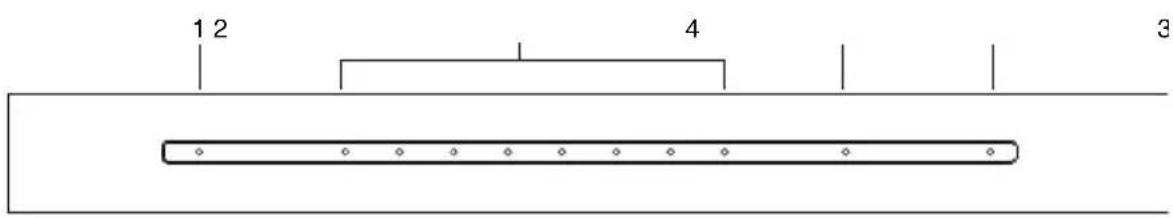
Components
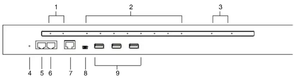
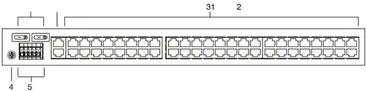
SN0108CO / SN0108COD Front View
SN0116CO / SN0116COD Front View
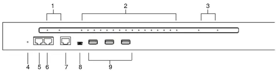
No. Component Description
1 Power LEDs Lights when the unit is powered up and ready to operate.
2 Port LEDs The Port
- Flashes Green: Active – data is being transmitted through the port
3 LAN LEDs Primary and Secondary 10/100/1000 Mbps LAN LEDs.
◆ RED: 10 Mbps
◆ RED + GREEN (ORANGE): 100 Mbps
◆ GREEN: 1000 Mbps
- Flashes to indicate that the Serial Console Server is being accessed over the LAN.
No. Component Description
| 4 | Reset Switch | Note: This switch is recessed and must be pushed with a small object such as the end of a paper clip, or a ballpoint pen.◆ Pressing and releasing this switch when the unit is running performs a system reset.◆ Pressing and holding this switch in for more than three seconds when the unit is running resets its configuration to the factory default settings.Note: This does not clear User Account information.See Clear Login Information, page 157, for information on clearing user account information.◆ Pressing and holding this switch while powering on the switch returns the unit to its factory default firmware level, rather than the firmware version that the switch has been upgraded to. This allows you to recover from a failed firmware upgrade and gives you the opportunity to try upgrading the firmware again.Note: This operation should only be performed in the event of a firmware upgrade failure that results in the device becoming inoperable. |
5 PON Port Reserved.
| 6 Modem Port For dial in connection should the unit be unavailable over the network. See Serial Console Server Installation, page 27, step 6 for installation details. | |
| 7 Local Console Port | This RJ45 port allows for local administration and access through a serial terminal connection to a computer. An SA0141 (DTE to DTE) adapter (included in the package) is required for this connection. |
| 8 Laptop USB Console Port | This mini-USB port allows a PC or laptop to be connected for local access and control. Connect to a PC or laptop to automatically launch a terminal emulator to access the SN text menu. |
| 9 USB Ports These three Type A female USB ports can be used to connect USB devices, such as USB storage devices (pen drive / hard drive), USB hubs and USB SIM card Reader. | |
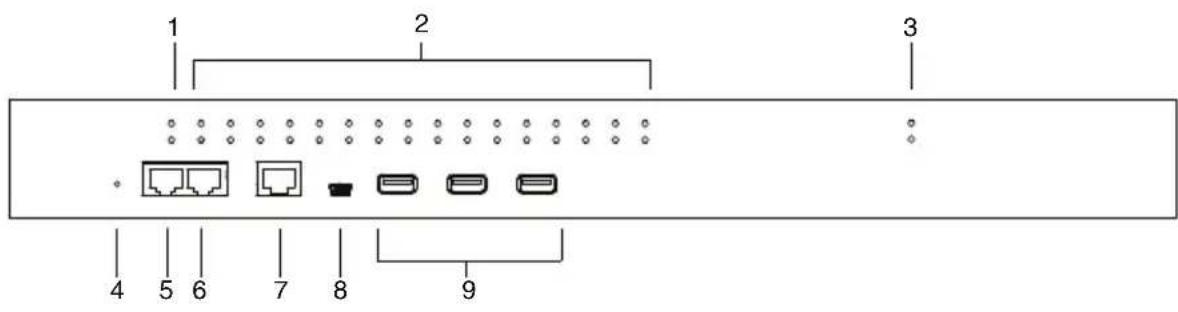
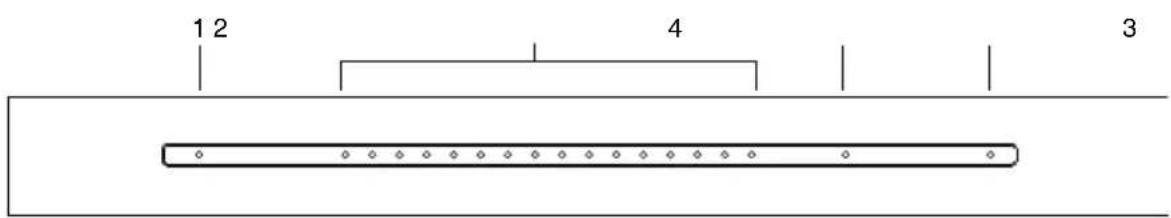
SN0132CO / SN0132COD Front View
SN0148CO / SN0148COD Front View
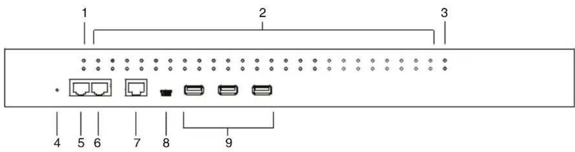
No. Component Description
1 Power LEDs Lights when the unit is powered up and ready to operate.
2 Port LEDs The Port LEDs provide status information about their corresponding serial ports.
- Lights Green: Online – the serial device attached to the port is powered on and ready.
- Flashes Green: Active – data is being transmitted through the port
3 LAN LEDs Primary and Secondary 10/100/1000 Mbps LAN LEDs.
◆ RED: 10 Mbps
◆ RED + GREEN (ORANGE): 100 Mbps
◆ GREEN: 1000 Mbps
- Flashes to indicate that the Serial Console Server is being accessed over the LAN.
No. Component Description
| 4 | Reset Switch | Note: This switch is recessed and must be pushed with a small object such as the end of a paper clip, or a ballpoint pen. |
| Pressing and releasing this switch when the unit is running performs a system reset.Pressing and holding this switch in for more than three seconds when the unit is running resets its configuration to the factory default settings.Note: This does not clear User Account information.See Clear Login Information, page 157, for information on clearing user account information. | ||
| Pressing and holding this switch while powering on the switch returns the unit to its factory default firmware level, rather than the firmware version that the switch has been upgraded to. This allows you to recover from a failed firmware upgrade and gives you the opportunity to try upgrading the firmware again.Note: This operation should only be performed in the event of a firmware upgrade failure that results in the device becoming inoperable. |
5 PON Port Reserved.
| 6 Modem Port For dial in connection should the unit be unavailable over the network. See Serial Console Server Installation, page 27, step 6 for installation details. | |
| 7 Local Console Port | This RJ45 port allows for local administration and access through a serial terminal connection to a computer. An SA0141 (DTE to DTE) adapter (included in the package) is required for this connection. |
| 8 Laptop USB Console Port | This mini-USB port allows a PC or laptop to be connected for local access and control. Connect to a PC or laptop to automatically launch a terminal emulator to access the SN text menu. |
| 9 USB Ports These three Type A female USB ports can be used to connect USB devices, such as USB storage devices (pen drive / hard drive), USB hubs and USB SIM card Reader. | |
SN9108CO Front View
SN9116CO Front View
No. Component Description
1 Power LED Lights when the unit is powered up and ready to operate.
2 Port LEDs The Port LEDs provide status information about their corresponding serial ports.
- Lights Green: Online – the serial device attached to the port is powered on and ready.
- Flashes Green: Active – data is being transmitted through the port
3 LAN LED Primary and Secondary 10/100/1000 Mbps LAN LEDs.
◆ RED: 10 Mbps
◆ RED + GREEN (ORANGE): 100 Mbps
◆ GREEN: 1000 Mbps
- Flashes to indicate that the Serial Console Server is being accessed over the LAN.
No. Component Description
4 Reset Switch
Note: This switch is recessed and must be pushed with a small object such as the end of a paper clip, or a ballpoint pen.
- Pressing and releasing this switch when the unit is running performs a system reset.
- Pressing and holding this switch in for more than three seconds when the unit is running resets its configuration to the factory default settings.
Note: This does not clear User Account information. See Clear Login Information, page 157, for information on clearing user account information.
- Pressing and holding this switch while powering on the switch returns the unit to its factory default firmware level, rather than the firmware version that the switch has been upgraded to. This allows you to recover from a failed firmware upgrade and gives you the opportunity to try upgrading the firmware again.
Note: This operation should only be performed in the event of a firmware upgrade failure that results in the device becoming inoperable.
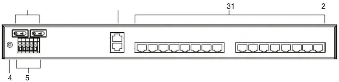
SN0108CO Rear View
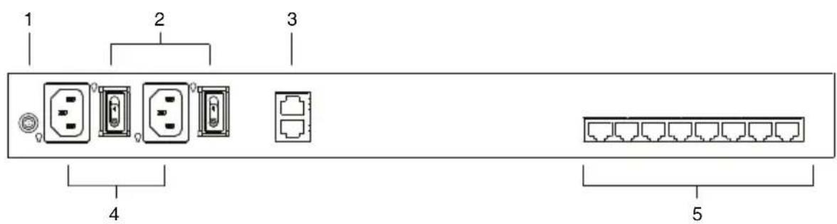
SN0116CO Rear View

| No. Component Description | |
| 1 Grounding Terminal | The grounding wire that is used to ground the unit attaches here. |
| 2 Power Switches | These standard rocker switches power the unit on and off. |
| 3 LAN Ports The cables that connect the unit to the primary and the backup network interfaces (10/100/1000 Mbps) plug in here. | |
| 4 Power Sockets The power cable(s) plugs in here. | |
| 5 Serial Ports The Cat 5e cables that connect to the serial devices or RJ45-to-Serial adapters plug in here. | |
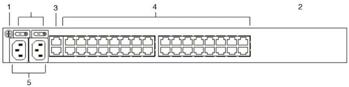
SN0108COD Rear View (DC Power)
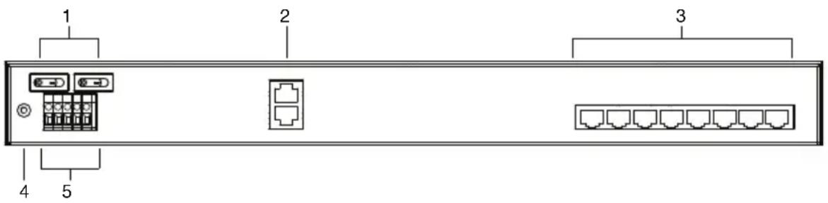
SN0116COD Rear View (DC Power)
No. Component Description
| 1 Power Switches | These standard rocker switches power the unit on and off. |
| 2 LAN Ports The cables that connect the unit to the primary and the backup network interfaces (10/100/1000 Mbps) plug in here. | |
| 3 Serial Ports The Cat 5e cables that connect to the serial devices or RJ45-to-Serial adapters plug in here. | |
| 4 Grounding Terminal | The grounding wire that is used to ground the unit attaches here. |
| 5 DC Terminal Block | The electric leads from your power source connect to this DC terminal block. |
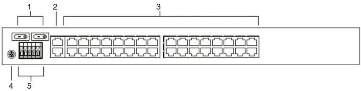
SN0132CO Rear View
SN0148CO Rear View
| No. Component Description | |
| 1 Grounding Terminal | The grounding wire that is used to ground the unit attaches here. |
| 2 Power Switches | These standard rocker switches power the unit on and off. |
| 3 LAN Ports The cables that connect the unit to the primary and the backup network interfaces (10/100/1000 Mbps) plug in here. | |
| 4 Serial Ports The Cat 5e cables that connect to the serial devices or RJ45-to-Serial adapters plug in here. | |
| 5 Power Sockets The power cable(s) plugs in here. | |
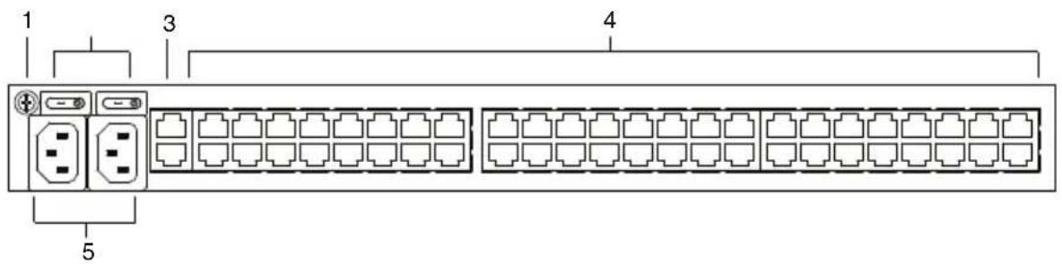
SN0132COD Rear View (DC Power)
SN0148COD Rear View (DC Power)
| No. Component Description | |
| 1 Power Switches | These standard rocker switches power the unit on and off. |
| 2 LAN Ports The cables that connect the unit to the primary and the backup network interfaces (10/100/1000 Mbps) plug in here. | |
| 3 Serial Ports The Cat 5e cables that connect to the serial devices or RJ45-to-Serial adapters plug in here. | |
| 4 Grounding Terminal | The grounding wire that is used to ground the unit attaches here. |
| 5 DC Terminal Block | The electric leads from your power source connect to this DC terminal block. |
SN9108CO Rear View
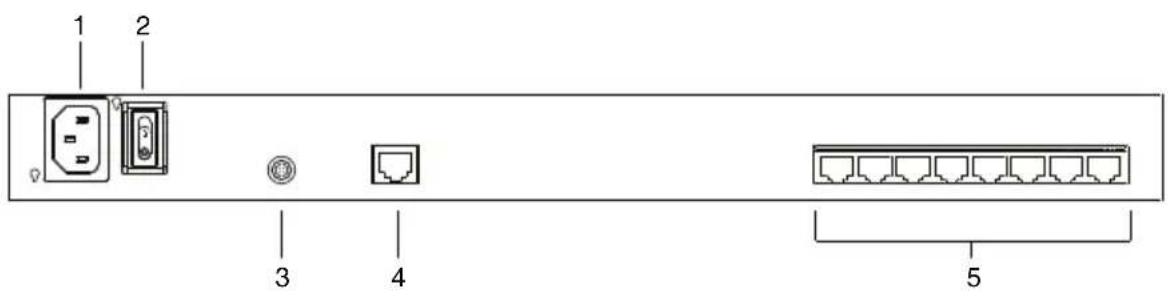
SN9116CO Rear View
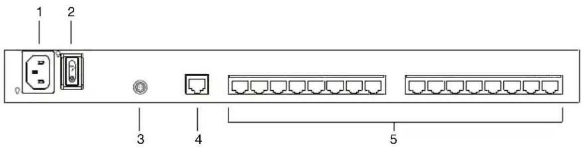
No. Component Description
1 Power Socket The power cable(s) plugs in here.
2 Power Switch This standard rocker switches power the unit on and off.
3 Grounding Terminal The grounding wire that is used to ground the unit attaches here.
4 LAN Port The cable that connect the unit to the network interface (10/100/1000 Mbps) plugs in here.
5 Serial Ports The Cat 5e cables that connect to the serial devices or RJ45-to-Serial adapters plug in here.
This Page Intentionally Left Blank
Before You Begin

-
Important safety information regarding the placement of this device is provided on page 139. Please review it before proceeding.
-
Make sure that the power to any device that you connect to the installation has been turned off. You must unplug the power cords
Stacking and Rack Mounting
The Serial Console Server can be stacked on the desktop or rack mounted in a variety of ways. The following sections take you through the procedures for each method.
Stacking
The Serial Console Server can be placed on any appropriate level surface that can safely support its weight plus the weight of its attached cables. To place the device, or to stack units if you are daisy-chaining them, remove the backing material from the bottom of the rubber feet that came with your package, and stick them onto the device's bottom panel at the corners, as shown in the diagram, on the following page:
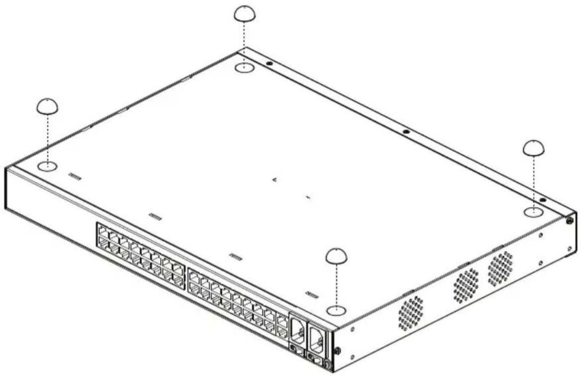
natural_image
Isometric line drawing of a server rack with ports and ventilation slots (no text or labels)Note: To ensure adequate ventilation, allow at least 5.1 cm on each side, and 12.7 cm behind the unit for power cord and cable clearance.
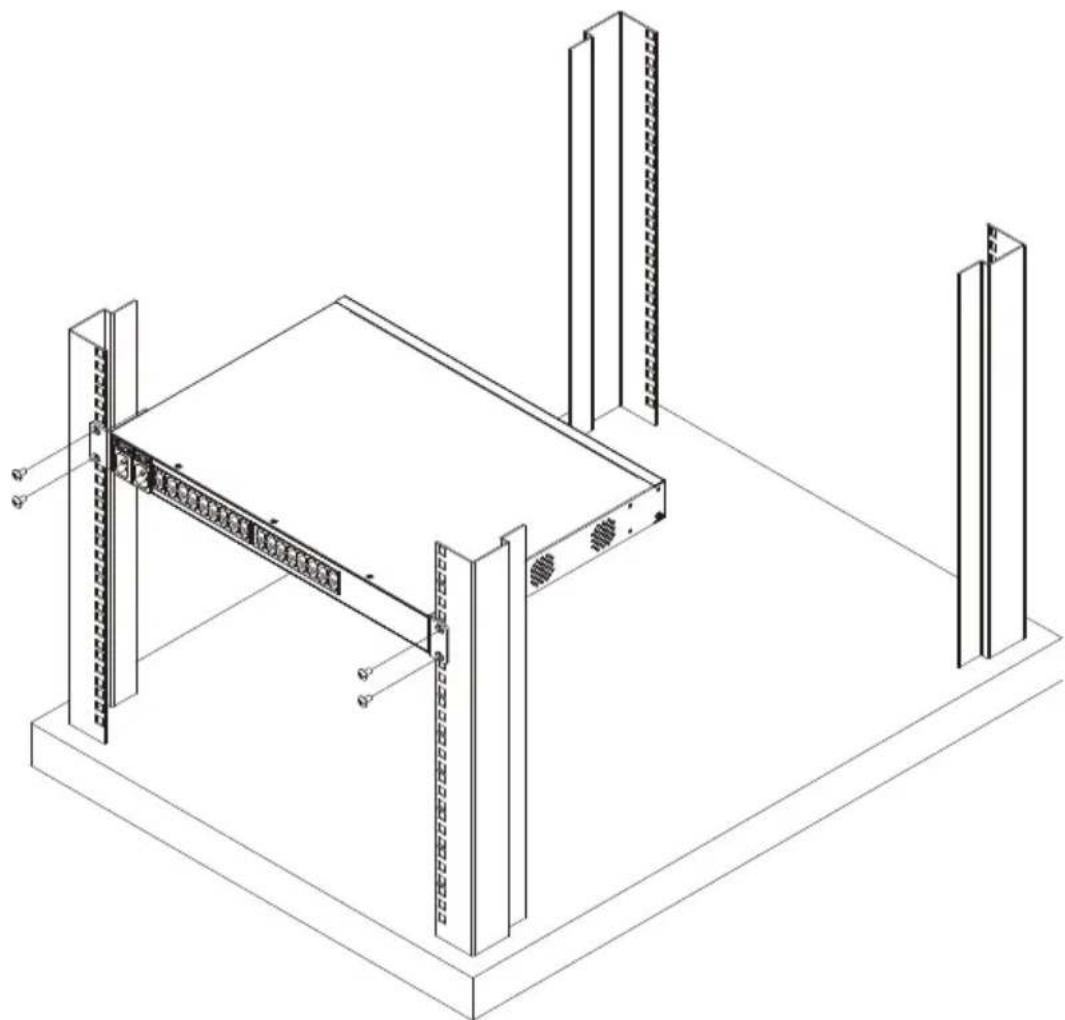
Rack Mounting
The Serial Console Server can be mounted in a 19" (1U) rack. The mounting brackets can screw into either the front or the back of the unit so that it can attach to the front or the back of the rack.
Rack Mounting - Front
To mount the unit at the front of the rack, do the following:
- Remove the two screws at the front of the unit.

natural_image
Isometric line drawing of a rectangular electronic device with ports and ventilation slots (no text or symbols)- Use the M3 x 8 Phillips head hex screws supplied with the rack mount kit to screw the rack mounting brackets into the front of the unit.
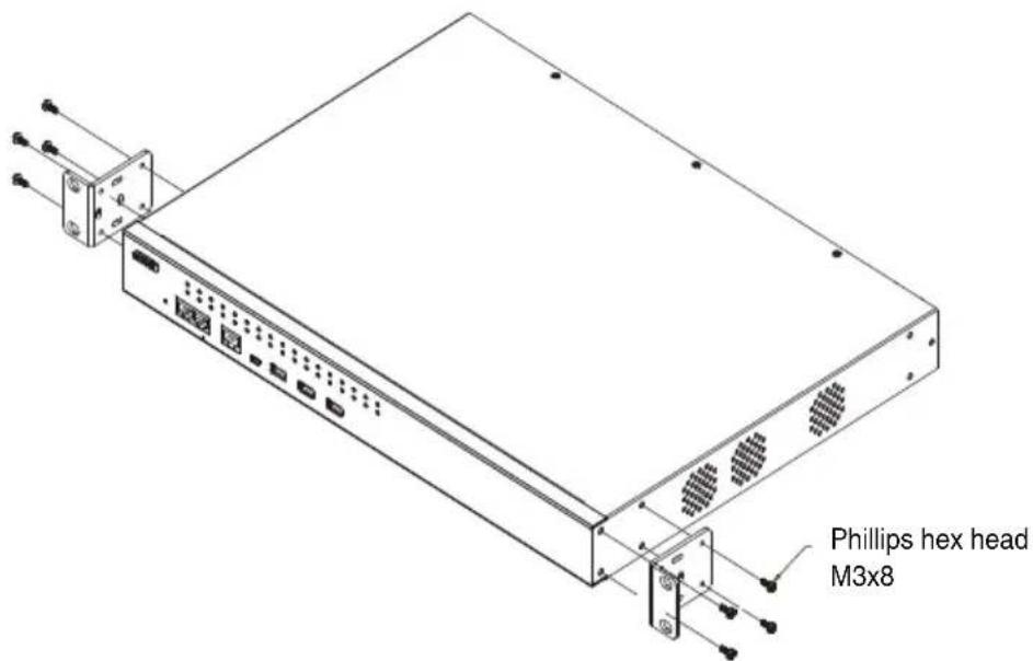
- Position the device in the front of the rack and align the holes in the mounting brackets with the holes in the rack.
- Screw the mounting brackets to the rack.
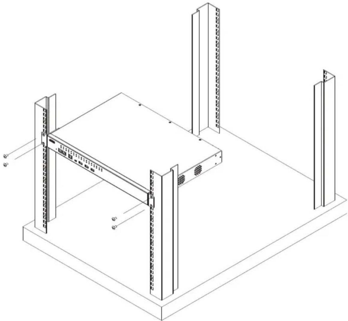
natural_image
Isometric line drawing of a server rack with vertical supports and mounting points (no text or symbols)Note: Cage nuts are provided for racks that are not pre-threaded.
Rack Mounting - Rear
To mount the unit at the rear of the rack, do the following:
- Remove the two screws at the rear of the unit.
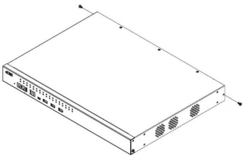
natural_image
Isometric line drawing of a rectangular electronic device with ports and ventilation slots (no text or symbols)- Use the M3 x 8 Phillips head hex screws supplied with the rack mounting kit to screw the rack mounting brackets into the rear of the unit.
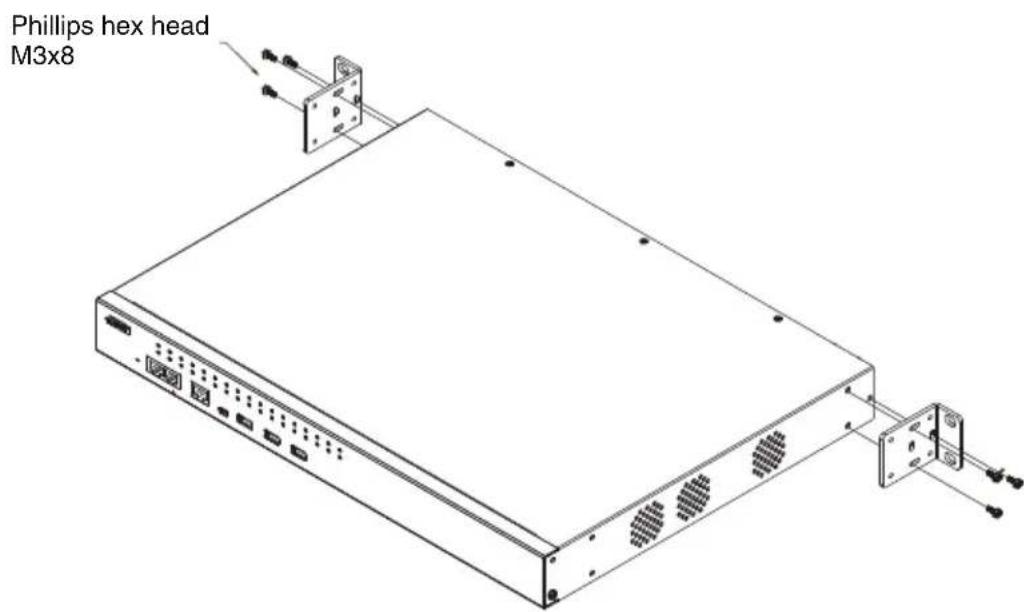
-
Position the device in the rack and align the holes in the mounting brackets with the holes in the rack.
-
Screw the mounting brackets to the rear of the rack.
natural_image
Isometric line drawing of a structural frame assembly with vertical supports and mounting points (no text or symbols)Note: Cage nuts are provided for racks that are not pre-threaded.
Serial Console Server Installation
SN0108CO / SN0116CO / SN0132CO / SN0148CO Installation
To set up your SN0108CO / SN0116CO / SN0132CO / SN0148CO installation, refer to the Installation Diagram on page 29. The numbers in the diagram correspond to the numbers of the instruction steps, below:
- Use a grounding wire to ground the unit by connecting one end of the wire to the Serial Console Server's grounding terminal (located on the back panel), and the other end of the wire to a suitable grounded object.
Note: Do not omit this step. Proper grounding helps to prevent damage to the unit from surges or static electricity.
- For each server or serial device with a DB-9 connector, connect a Cisco Console Cable or a Cat 5e cable with RJ-45-to-DB-9(F) adapter between its serial port and any available RJ-45 port on the Serial Console Server's rear panel.
Note: Refer to DB-9/DB-25 Interface on page 159 for pin assignments.
- Connect a Cat 5e cable between a Cisco Network Switch (or any compatible network switch) and any available RJ-45 port on the Serial Console Server's rear panel.
Note: For a compatible network switch, please make sure the RJ-45 port pin definition of the target device matches the Serial Console Server.
-
Connect the Serial Console Server to the network by connecting both the primary and backup LAN ports, located on the unit's rear panel, to the network with Cat 5e cables.
-
(Optional) If you choose to install a serial modem for OOB operation, connect a Cisco Console Cable to a null modem adapter. Plug the DB-9 connector into the Modem and the RJ-45 connector into the Modem Port on the Serial Console Server's front panel.
-
(Optional) Connect a Cat 5e cable between an ATEN PDU and the PON Port on the Serial Console Server's front panel for power management.
-
(Optional) If you wish to use a console terminal connection, use a Cisco Console Cable to connect between the Serial Console Server's Local
Console Port on the front panel and the DB-9 connector of a console terminal (or a computer).
For the console terminal or computer without DB-9 connector, you can use a Cat 5e cable with UC232B to connect between the Local Console Port and the USB port of the console terminal (or the computer).
Note: The UC232B USB to RJ-45 (RS-232) Console Adapter is sold separately. Contact you ATEN dealer for product information.
- (Optional) If you are using a laptop USB console to control the Serial Console Server locally, use the laptop USB console cable included in the package to connect the laptop to the LUC port on the Serial Console Server's front panel.
- (Optional) If you are using USB devices (such as USB storage devices) with your Serial Console Server, connect them to these three Type A female USB ports.
- For AC models: Use the AC power cord provided with this package to connect the SN0108CO/SN0116CO/SN0132CO/SN0148CO's Power Socket to an AC power source. For DC models: Connect the DC power source to the SN0108COD/SN0116COD/SN0132COD/SN0148COD's DC terminal block.
- Turn on the power switch.
SN0108CO / SN0116CO / SN0132CO / SN0148CO Installation Diagram
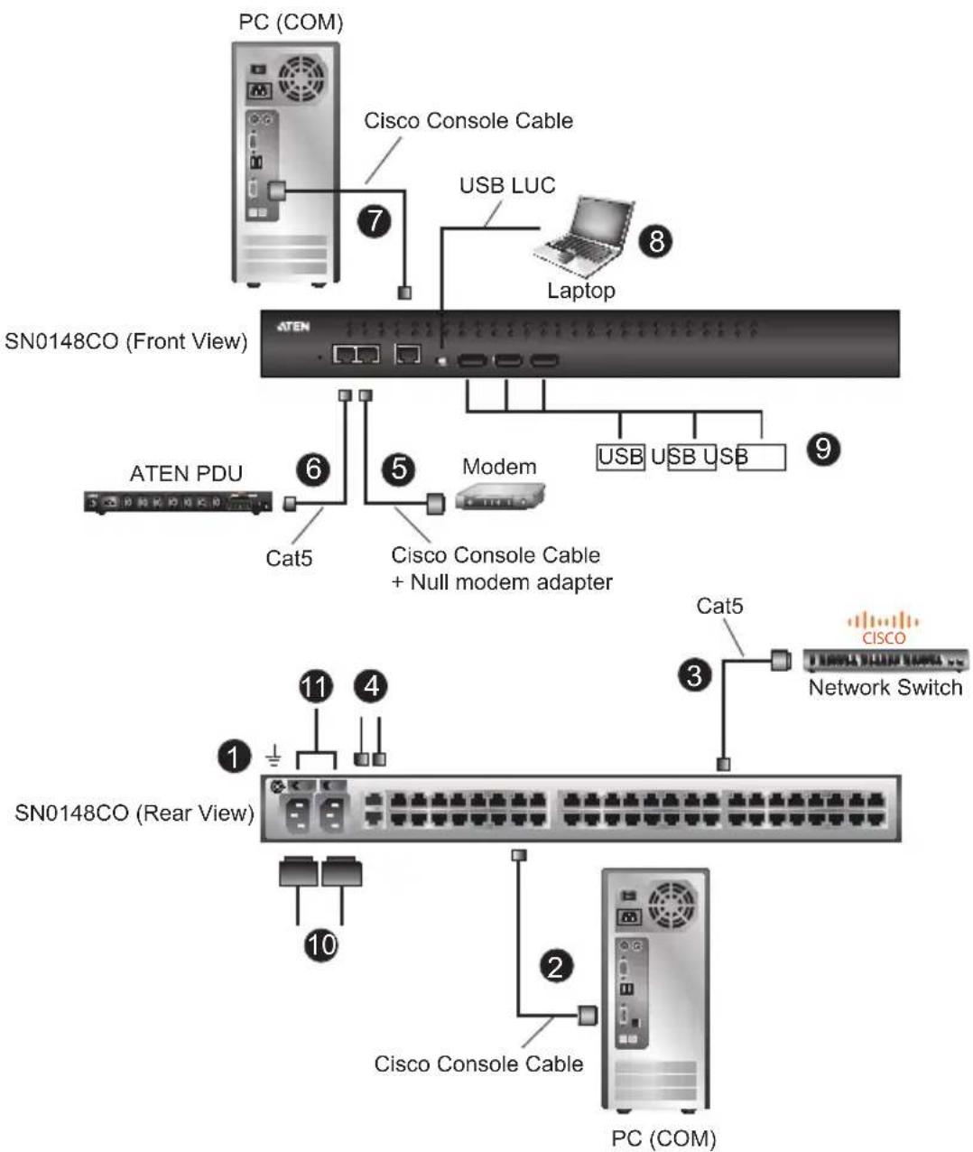
Note: The example above shows a SN0148CO Serial Console Server. The SN0108CO / SN0116CO / SN0132CO units have the same ports and switches but with slightly different layouts. See Components, page 9 for details.
SN9108CO / SN9116CO Installation
To set up your SN9108CO / SN9116CO installation, refer to the Installation Diagram on page 31. The numbers in the diagram correspond to the numbers of the instruction steps, below:
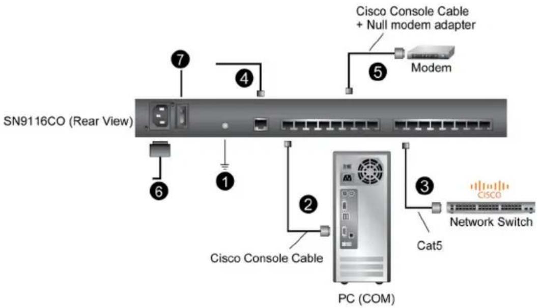
- Use a grounding wire to ground the unit by connecting one end of the wire to the Serial Console Server's grounding terminal (located on the back panel), and the other end of the wire to a suitable grounded object.
Note: Do not omit this step. Proper grounding helps to prevent damage to the unit from surges or static electricity.
- For each server or serial device with a DB-9 connector, connect a Cisco Console Cable or a Cat 5e cable with RJ-45-to-DB-9(F) adapter between its serial port and any available RJ-45 port on the Serial Console Server's rear panel.
Note: Refer to DB-9/DB-25 Interface on page 159 for pin assignments.
- Connect a Cat 5e cable between a Cisco Network Switch (or any compatible network switch) and any available RJ-45 port on the Serial Console Server's rear panel.
Note: For a compatible network switch, please make sure the RJ-45 port pin definition of the target device matches the Serial Console Server.
- Connect the Serial Console Server to the network by connecting the LAN port to the network with Cat 5e cables.
- (Optional) If you choose to install a serial modem for OOB operation, connect a Cisco Console Cable to a null modem adapter. Plug the DB-9 connector into the Modem and the RJ-45 connector into any available RJ-45 port on the Serial Console Server's front panel.
- For AC models: Use the AC power cord provided with this package to connect the SN9108CO/SN9116CO's Power Socket to an AC power source.
- Turn on the power switch.
SN9108CO / SN9116CO Installation Diagram
This Page Intentionally Left Blank
Overview
This chapter discusses the administrative procedures that the Super Administrator performs to get the Serial Console Server set up for the first time.
First Time Setup
Once the Serial Console Server has been cabled up, the Super Administrator needs to set up the unit for operation. This involves setting the network parameters, and changing the default Super Administrator login. The most convenient way to do this for the first time is from a local console (local VT console or a local computer running terminal application software, such as Microsoft HyperTerminal), or a Laptop USB Console (LUC) running the SNViewerUSB application (SN0108CO / SN0116CO / SN0132CO / SN0148CO only). Setup can also be done remotely over the Web via the GUI using the unit's IP address.
Note: For remote methods of setting up the network, see IP Address Determination, page 150.
Local Login
You can log in locally from a computer or laptop (SN0108CO / SN0116CO / SN0132CO / SN0148CO only) connected directly to the Serial Console Server (see Serial Console Server Installation, page 27). There are two methods for logging in locally SNViewerUSB and HyperTerminal.
The local login Main Menu is the text based equivalent of the browser based configuration and control functions described throughout this manual. You can reference the detailed information provided for the web browser version (Browser Login, page 37) as you work your way through the sub-menus to configure the settings discussed in this chapter.
Laptop USB Console (LUC) Login - SNViewerUSB
The SNViewerUSB application appears automatically when a Laptop USB Console (LUC) connection (SN0108CO / SN0116CO / SN0132CO / SN0148CO only) has been established, and you will be prompted to log in, as shown here:
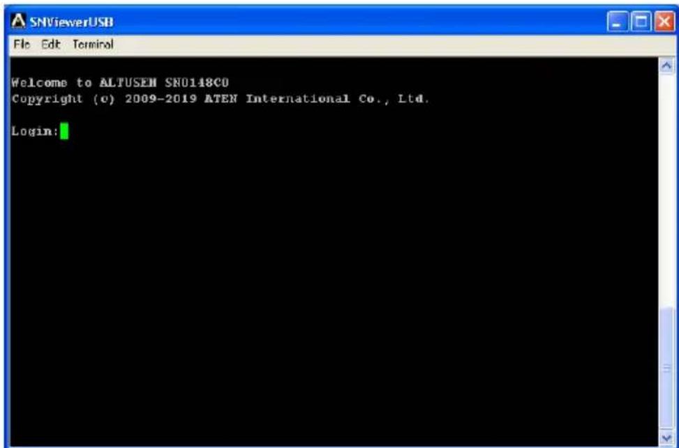
Since this is the first time you are logging in, use the default Username: administrator; and the default Password: password.
Console Login - HyperTerminal
Once a physical connection from a computer to the Serial Console Server has been made you can establish a HyperTerminal session using the instructions below.
- Open HyperTerminal, and configure the port settings for the COM1 port:
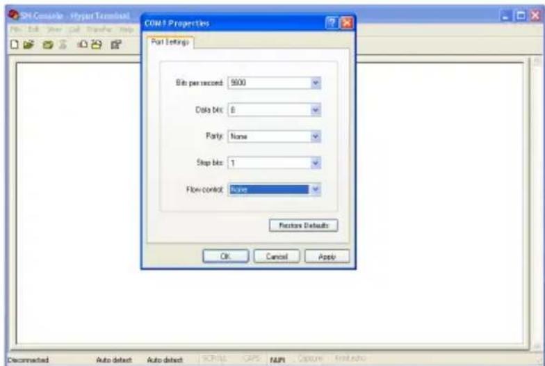
Bits per Second: 9600, Data Bits: 8, Parity: None, Stop bits: 1, Flow Control: None.
- When configured correctly the login prompt appears, as shown here:
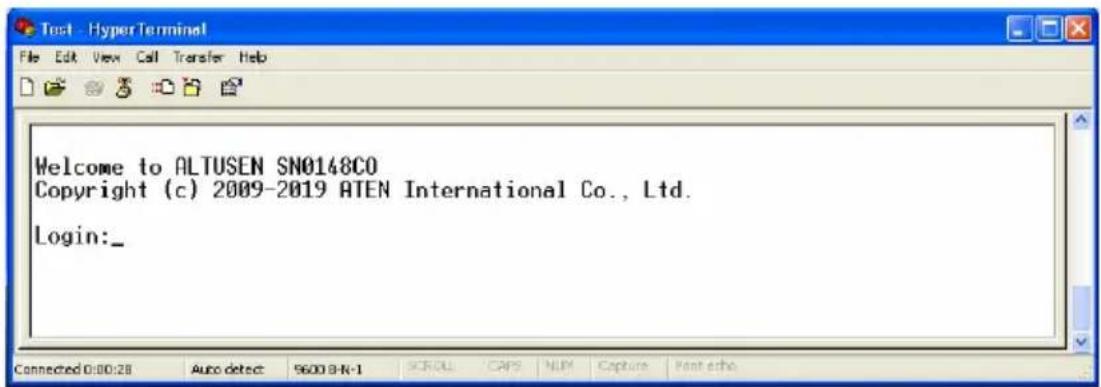
Since this is the first time you are logging in, use the default Username: administrator; and the default Password: password.
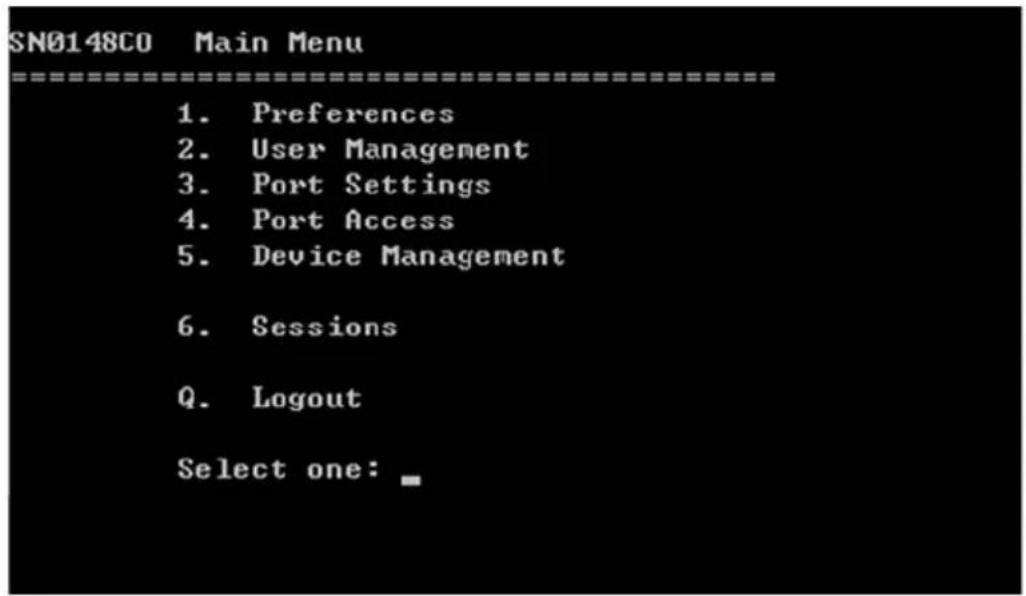
Local Console Main Menu
After you log in via HyperTerminal or SNViewerUSB the text based menu appears:
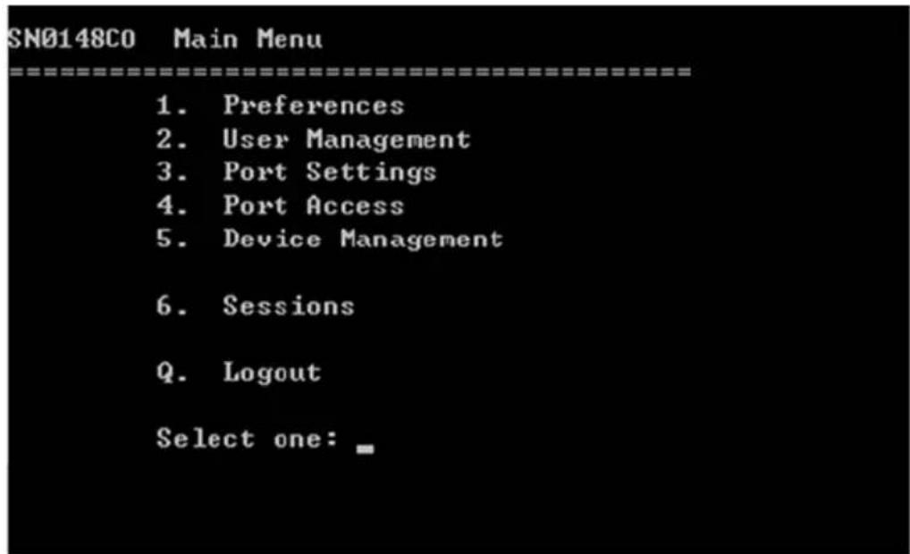
The Main Menu is the text based equivalent of the browser based configuration and control functions described throughout this manual. You can reference the information provided for the browser version as you work your way through the sub-menus.
Remote Login
You can log in remotely from a computer running Telnet, PuTTY, or via Web Browser.
The remote login Main Menu for Telnet and PuTTY are a text based equivalent of the browser based GUI and control functions as described throughout this manual. You can reference the detailed information provided for the web browser version (Browser Login, page 37) as you work your way through the text sub-menus and configure the settings discussed in this chapter.
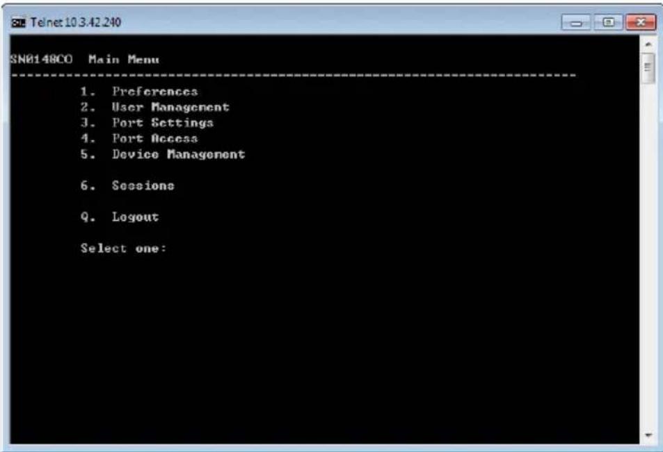
Telnet Login
Start Telnet, type “open 192.168.0.60”, press Enter, and a login prompt will appear, as show here:
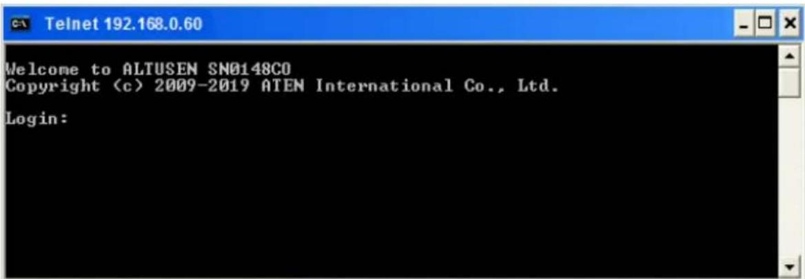
Since this is the first time you are logging in, use the default Username: administrator; and the default Password: password.
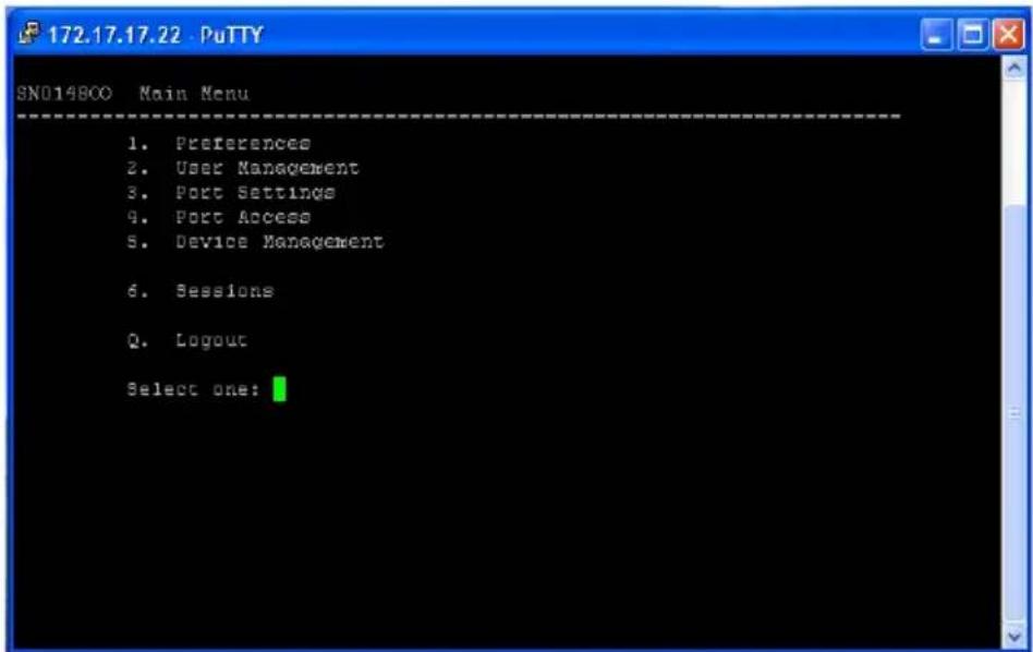
PuTTY Login
Start PuTTY, enter the Serial Console Server's default IP address (192.168.0.60), click Open, and a login prompt will appear, as shown here:
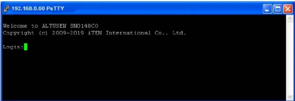
Since this is the first time you are logging in, use the default Username: administrator; and the default Password: password.
Browser Login
Once the Serial Console Server has been connected to the LAN, it can be accessed via an Internet browser running on any platform. To access the Serial Console Server, do the following:
-
Open the web browser and specify the default IP address (192.168.0.60) of the Serial Console Server in the browser's location bar, and press Enter.
-
When a Security Alert dialog box appears, accept the certificate, it can be trusted.
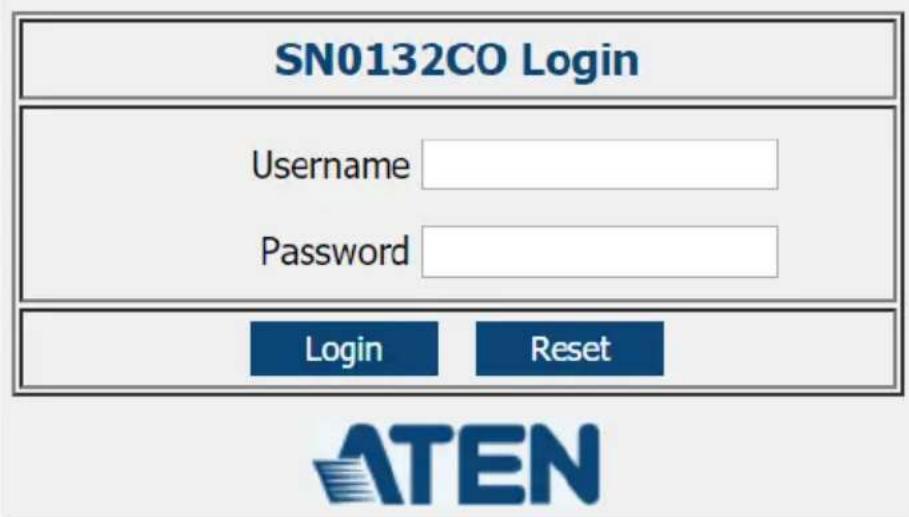
Once you accept the certificate(s), the login page appears:
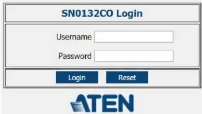
- Since this is the first time you are logging in, use the default Username: administrator; and the default Password: password.
Note: For security purposes, you should change these to a unique Username and Password. (See Changing the Super Administrator Login, page 39 for details.)
After you successfully log in, the Main Page appears:
![Port List Port Number Port Name Status Busy Operating Mode Operation Port [01] COM1 - - Console Management SSH Dump Buffer -/5101 [02] COM2 - - Console Management SSH Dump Buffer -/5102 [03] COM3 - - Console Management SSH Dump Buffer -/5103 [04] COM4 - - Console Management SSH Dump Buffer -/5104 [05] COM5 - - Console Management SSH Dump Buffer -/5105 [06] COM6 - - Console Management SSH Dump Buffer -/5106 [07] COM7 - - Console Management SSH Dump Buffer -/5107 [08] COM8 - - Console Management SSH Dump Buffer -/5108 [09] COM9 - - Console Management SSH Dump Buffer -/5109 [10] COM10 - - Console Management SSH Dump Buffer -/5110 [11] COM11 - - Console Management SSH Dump Buffer -/5111 [12] COM12 - - Console Management SSH Dump Buffer -/5112 [13] COM13 - - Console Management SSH Dump Buffer -/5113 ATEN International Co., Ltd. All rights reserved.](/content/2026/06/1204310/images/a213f0da1da0211f80ebf113e7aca20b8785e97e599ffabb33aa64303d2d5c29.jpg)
Setup
Network Setup
To set up the network, do the following:
- Click the Device Management tab.
- Select the Network tab.
![Port Access User Management Device Management Log Maintenance ATEN Welcome to the SN0132CO SN0132C0 [01]COM1 [02]COM2 [03]COM3 [04]COM4 [05]COM5 [06]COM6 [07]COM7 [08]COM8 [09]COM9 [10]COM10 [11]COM11 [12]COM12 [13]COM13 [14]COM14 Network Information IP Installer Enabled View Only Disabled Service Ports HTTP Port: 80 HTTPS Port: 443 SSH Port: 22 Telnet Port: 23 Base Socket: 5001 Network Configuration Enable Redundant NIC Select a network adapter [Redundant(eth0, eth1)] IPv4 Configuration IPv6 Configuration Obtain IP address automatically Obtain IP address automatically Set IP address manually Set IP address manually Show ATEN International Co., Ltd. All rights reserved.](/content/2026/06/1204310/images/bf4efe4eaf41f9f093ea7d526f85c4041066f7467777d1e38eed6df9b9d8a5c5.jpg)
- Fill in the fields according to the information provided under Network, page 100.
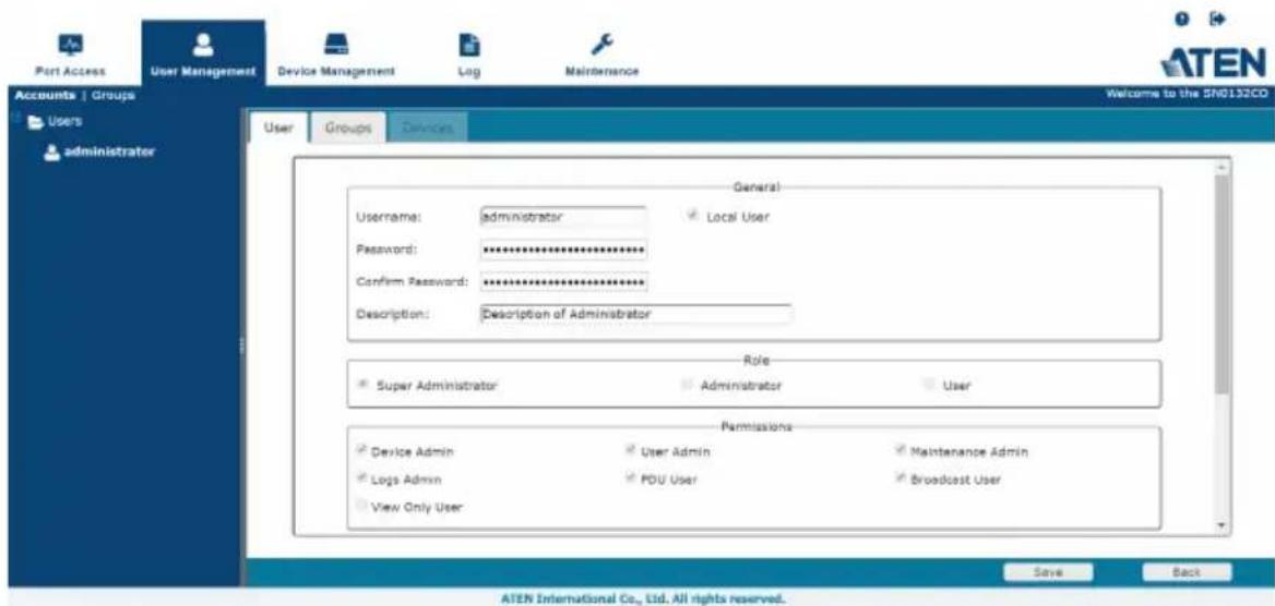
Changing the Super Administrator Login
To change the default Super Administrator Username and Password, do the following:
- At the top of the screen, click the User Management tab.
The User Management page has a list of Users and Groups in the Sidebar at the left, and a more detailed list of users – with more information about them – in the large central panel. Since this is the first time the page is being accessed, only the Super Administrator appears:

- Click on the account in the left panel or select it in the central panel, then click Modify (at the bottom of the page.)
The User Information page appears:
-
Change the Username and Password to something unique.
-
Enter the password again in the Confirm Password field to confirm it is correct.
- Click Save (located at the bottom of the page).
- When the dialog box informing you that the change completed successfully appears, Click OK.
Overview
Once you have successfully logged in, the Serial Console Server's Main Page appears. The look of the page varies slightly, depending on which method you used to log in. Each of the interfaces is described in the sections that follow.
Access
The Serial Console Server can be accessed from a local console (locally connected computer or laptop) running terminal application software (such as Microsoft HyperTerminal) or the SNViewerUSB application; or from a remote computer using Telnet (SSH), PuTTY, or web-based browser (see First Time Setup, page 33 for details).
No matter which access method you choose, the Serial Console Server's authentication procedure requires you to submit a valid username and password. If you supply invalid login information, the authentication routine will return an Invalid Username or Password, or Login Failed message. If you see this type of message, log in again with a correct username and password.
Note: If the number of invalid login attempts exceeds a specified amount, a timeout period is invoked. You must wait until the timeout period expires before you can attempt to log in again. See Login Failures, page 119 for further details.
Local Console Operation
When a local console is attached (SN0108CO / SN0116CO / SN0132CO / SN0148CO only, see page 27), you can use the HyperTerminal or SNViewerUSB application to log in (See Local Login, page 33 for details). Simply key in your valid Username and Password, then hit [Enter] to bring up the Local Console Main Page.
The Main Menu is the text based equivalent of the browser based configuration and control functions described throughout this manual. You can reference the information provided for the browser version as you work your way through the sub-menus.
Note: 1. As with the browser version, access to many of these sub-menus are restricted by the user's permissions. If you select a submenu that you are not authorized for, nothing happens.
2. Some of the sub-menus do not have an Exit choice. In these cases, you can return to the previous menu without making changes by pressing Enter twice.
3. You can bring up the Main Menu at any time during your session.
4. This menu can also be accessed from remote terminal sessions, such as Windows Telnet Client, and PuTTY.
When you have finished with your session, bring up the Main Menu and press Q to log out. After you are offline, you can simply close the window.
Remote Operation
You can access the Serial Console Server remotely using a web browser, or text based terminal application such as Telnet or PuTTY, as described below.
Web Browser Login
Serial Console Server units can be accessed via an Internet browser running on any platform. To access the Serial Console Server, do the following:
-
Open the browser and specify the IP address (See Browser Login, page 37 for details) of the Serial Console Server you want to access in the browser's location bar.
-
When a Security Alert dialog box appears, accept the certificate – it can be trusted. If a second certificate appears, accept it as well.
Once you accept the certificate(s), the login page appears:
- Provide your username and password (see Browser Login, page 37), then click Login to bring up the Web Browser Main Page, described on the next page.
The Web Browser Main Page
To ensure multi-platform operability, access to the Serial Console Server can be accomplished with most standard web browsers. The chapters following this one give detailed information about each section of the web browser. Once users log in and are authenticated (see page 43), the Web Browser Main Page comes up, with the Port Access page displayed:
![Port List Port Number Port Name States Busy Operating Holdt Operation Port [01] COM1 - - Consola Management SSH Dump Buffer -/9101 [02] COM2 - - Consola Management SSH Dump Buffer -/9102 [03] COM3 - - Consola Management SSH Dump Buffer -/9103 [04] COM4 - - Consola Management SSH Dump Buffer -/9104 [05] COM5 - - Consola Management SSH Dump Buffer -/9105 [06] COM6 - - Consola Management SSH Dump Buffer -/9106 [07] COM7 - - Consola Management SSH Dump Buffer -/9107 [08] COM8 - - Consola Management SSH Dump Buffer -/9108 [09] COM9 - - Consola Management SSH Dump Buffer -/9109 [10] COM10 - - Consola Management SSH Dump Buffer -/9110 [11] COM11 - - Consola Management SSH Dump Buffer -/9111 [12] COM12 - - Consola Management SSH Dump Buffer -/9112 [13] COM13 - - Consola Management SSH Dump Buffer -/9113 ATEN International Co., Ltd. All rights reserved.](/content/2026/06/1204310/images/8a254bc72f142cfe45b6cd7737a40464cb1bf43f74815c03d8d01a18c20eb2f0.jpg)
Note: The screen depicts a Super Administrator's page. Depending on a user's type and permissions, not all of these elements appear.
Page Components
The web page screen components are described in the table, below:
| No. | Item Description | |
| 1 | Tab Bar The tab bar contains | the Serial Console Server main operation categories. The items that appear in the tab bar are determined by the user's type, and the authorization options that were selected when the user's account was created. |
| 2 | Menu Bar The menu bar contains | operations operational sub-categories that pertain to the item selected in the tab bar. The items that appear in the menu bar are determined by the user's type, and the authorization options that were selected when the user's account was created. |
| 3 | Sidebar The Sidebar provides | a tree view listing of ports that relate to the various tab bar and menu bar selections. Clicking a node in the Sidebar brings up a page with the details that are relevant to it.There is a Filter button at the bottom of the Sidebar that lets you expand or narrow the scope of the ports that appear in the tree. |
| 4 | About About provides information regarding the Serial Console Server's current firmware version. | |
| 5 | Logout Click this button to log out of your Serial Console Server session. | |
| 6 | Welcome Message | If this function is enabled (see Welcome Message, page 67), a welcome message displays here. |
| 7 | Interactive Display Panel | This is your main work area. The screens that appear here reflect your menu choices and Sidebar node selection. |
The Tab Bar
The number and type of icons that appear on the Tab Bar at the top of the page are determined by the user's type (Super Administrator, Administrator, User) and the permissions assigned when the user's account was created. The chapters following this one give detailed information about each section of the web browser. The functions associated with each of the icons are explained in the table below:
| Icon Function | |
 | Port Access: The Port Access page is used to access and control the devices on the Serial Console Server installation. This page is available to all users. Port Access is discussed on page 59. |
 | User Management: The User Management page is used to create and manage Users and Groups. It can also be used to assign devices to them. This tab is available to the Super Administrator, as well as administrators and users who have been given User Management permission. The tab doesn't appear for other administrators and users. User Management is discussed on page 81. |
 | Device Management: The Device Management page is used to configure and control the overall operation of the Serial Console Server. This page is available to the Super Administrator, as well as administrators and users who have been given Device Management permission. The tab doesn't appear for other administrators and users. Device Management is discussed on page 97. |
 | Log: The Log page displays the contents of the log file. The Log page is discussed on page 127. |
 | Maintenance: The Maintenance page is used to install new firmware; backup and restore configuration and account information; restore default values; and import Certificates. This page is available to the Super Administrator (and Administrators and Users with Maintenance permission). The icon doesn't display on the page of ordinary administrators and users. The Maintenance page is discussed on page 131. |
There are two small icons at the extreme right of the page. Their functions are described in the table, below:
| Icon Function | |
 | Click this icon to bring up a panel with information about the Serial Console Server's firmware version. |
 | Click this icon to log out and end your Serial Console Server session. |
SNViewer
The SNViewer is the main application used to access serial devices via web browser. The SNViewer opens from the Port Access - Connections page, when you click the Telnet or SSH button for a serial device (see Telnet/SSH, page 63 for details). When the SNViewer opens there is a Control Panel toolbar that appears when your mouse moves over it, which allows you to configure your session, as shown here:
![SNViewer 80 * 24 Welcome to ALTUSEN S Copyright (c) 2009-2 10.3.42.178 5001 On Line Login:administrator Password: Connected to Port: 1 Press [Ctrl+ d] to go to the Suspend Menu.](/content/2026/06/1204310/images/7ab5202dbdb6229938d707b6cffa0f80e87d503fc0a225d9b5693ded05561b18.jpg)
SNViewer Control Panel
The SNViewer provides a Control Panel that is hidden at the upper center of the screen, and becomes visible when your mouse moves over it. The panel consists of three rows: an icon row at the top, and two text rows below it:

- By default, the upper text row shows the width and height of the window size. As the mouse pointer moves over the icons in the icon bar, however, the information in the upper text row changes to describe the icon's function. In addition, if a message from another user is entered in the message board, and you have not opened the message board in your session, the message board window will pop open automatically.
- The lower row shows the IP address and port of the device you are accessing on the left side, and the connection status on the right.
Control Panel Functions
The Control Panel functions are described below and in the following sections:
| Icon Function | |
 | This is a toggle. Click to make the Control Panel appear Always On Top - i.e., always displays on top of the SNViewer screen. Click again to have it display in Auto Hide mode- allowing it to only appear when the mouse is moved over it. |
 | Use this to copy the selected text on the screen. |
 | Use this to copy all text that is displayed on the screen. |
 | Use this to paste the copied text. |
 | Use this icon to toggle Logging on / Logging off. This starts a log file of characters sent from the serial device to the SNViewer. You must first create and import a text based log file (See Terminal Settings, Others - Log File, page 53). |
 | Use this to browse for data files to import (see Data Import, page 49). |
 | Use this to change the page encoding (see Encode, page 50). |
 | Use this icon to enable broadcasting. Broadcasting allows you to access and make changes on a single port and the same changes will be made across all Broadcast Ports. Before using the broadcast function, set the Broadcast Timeout and Broadcast Ports (see Preferences, page 66 for details). For broadcasting to work, you must first access a port set as a Broadcast Port and then click the Broadcast icon on the control panel. |
 | Click to send a Break command. |
| Icon Function | |
 | Use this to reset the terminal to its default settings. |
 | Click to bring up the Message Board (see The Message Board, page 50). |
 | Click to open a window and create a list of custom text macros (see Macros, page 51). |
 | Use this to change the font, color and other SNViewer settings (see Terminal Settings, page 52). |
 | Use this button to adjust the width of the SNViewer window. |
 | Click to exit the viewer. |

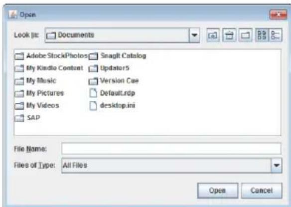
Data Import
The Data Import page opens a standard browse menu to import data files, as shown below:

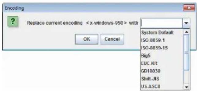
Encode
Encoding allows you select which type of encoding you want to use. Make your selection from the drop down menu and click OK, as shown below:

The Message Board
The Serial Console Server supports multiple user logins, which may cause access conflicts. To alleviate the problem, a message board has been provided, which allows users to communicate with each other:
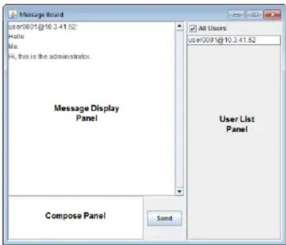
Message Display Panel
Messages that users post to the board are display in this panel.
Compose Panel
Key in the messages that you want to post to the board in this panel. Click Send to post the message to the board.
User List Panel
The username and IP address of all the logged in users are listed in this panel.
If you check All Users, messages are posted to all users. To post a message to one individual user, select the user's name before sending your message.
If a user's name is selected, and you want to post a message to all users, select All Users before sending your message.

Macros
Macros allow you to create custom text macros to use within the SNViewer application. When you click the Macros icon the following screen appears:
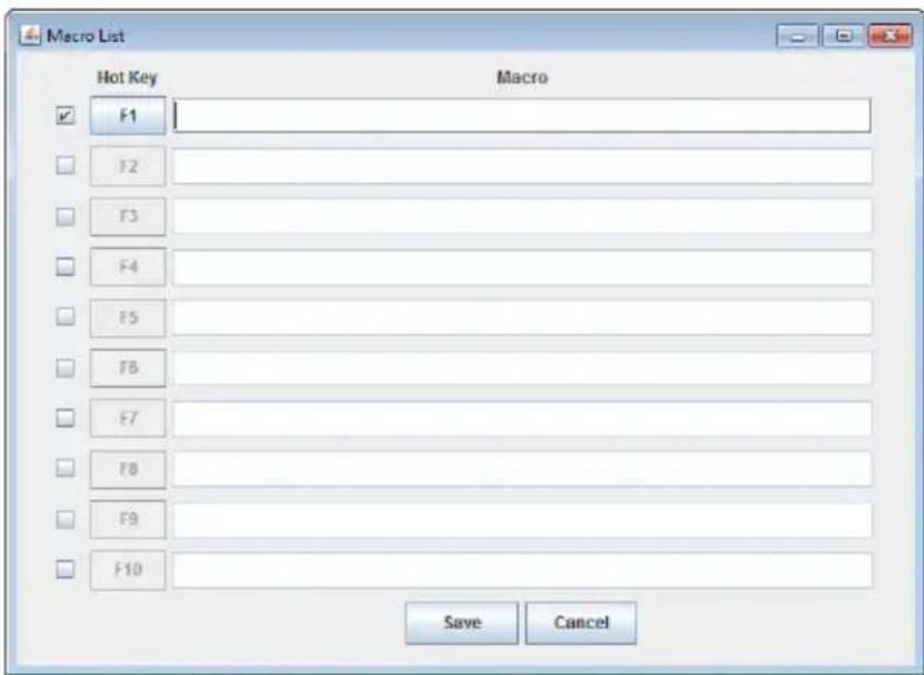
Simply check a box, type in the text macro and click Save. Use the associated function key (F1-F12) to run the custom text macro(s) you created. Terminal Application
You can log in remotely using a text based terminal application such as Telnet, or PuTTY. For information on how to connect and login, see Remote Login, page 36 for details.
The Telnet and PuTTY Main Menus are the text based equivalent of the browser based configuration and control functions described throughout this manual. You can reference the information provided for the browser version as you work your way through the sub-menus. Once you login, the following text based menu's appear:

Terminal Settings
The Terminal Settings page allows you make changes to the appearance of the terminal window, as described below:
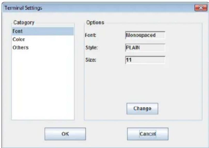
| Category Description | |
| Font | Click Change to configure the SNViewer's Font settings. You can change the Font type, Size, and Style. On the right side of the window you can view an example of the font you have set. |
| Color | Select an Option: Foreground color, Background Color, Cursor Text color, or Cursor Color, and Click Change to adjust the color settings. Use the HSL, Swatches, and HSV tabs to make detailed adjustments and select the colors.Below the tab is a Preview section you can use to see how the color change will look.Click OK to save the changes; Cancel to remove the changes and exit; or Reset to revert to the default color settings. |
| Category Description |
| Others Use this section to set: |
| ◆ Implicit CR in every LF: Checking this box adds an extra Carriage Return when the [Enter] key is used, so the cursor returns flush on the left margin. Use this function if the text is not lining up on the left margin after you hit [Enter]. |
| ◆ Backspace is Delete Key |
| ◆ Local echo: An echo is a response from the serial device of character(s) that have been input. |
| ◆ Auto: Characters that are typed in are echoed but not displayed on the screen. |
| ◆ Force On: Characters that are typed in are echoed and displayed on the screen as they are entered. Passwords are displayed on the screen if this mode is used. |
| ◆ Force Off: Characters are not echoed from the serial device. |
| ◆ Buffer Size: This is the maximum size of the Log file. |
| ◆ Log File: The log file generates a log of characters sent from the connected serial device to the SNViewer. The log must first be created as a text file using an external editor such as Note or Microsoft Word, then opened here. Next you must turn Logging on from the SNViewer Control Panel (see Control Panel Functions, page 48). |
Terminal Application
You can log in remotely using a text based terminal application such as Telnet, or PuTTY. For information on how to connect and login, see Remote Login, page 36 for details.
The Telnet and PuTTY Main Menus are the text based equivalent of the browser based configuration and control functions described throughout this manual. You can reference the information provided for the browser version as you work your way through the sub-menus. Once you login, the following text based menu's appear:
Telnet Menu-Driven Text UI
PuTTY Menu-Driven Text UI
Chapter 5
Port Operating Modes
Overview
To cover a broad range of serial applications, the Serial Console Server's COM ports support several port operating modes. These include Console Management and Console Management Direct modes for device control; and Real COM Port, Virtual Modem, TCP Server, TCP Client, and UDP Mode for Serial-to-Ethernet connectivity and applications that require COM ports, serial tunneling, or where TCP/UDP Socket functionality is needed. An explanation of the functions performed by the various operating modes is provided in the sections that follow.
![Port Access User Management Device Management Log Maintenance Connections | Favorites | History | Preferences | Sessions | Access | Properties SN0132CO [01]COM1 [02]COM2 [03]COM3 [04]COM4 [05]COM5 [06]COM6 [07]COM7 [08]COM8 [09]COM9 [10]COM10 [11]COM11 [12]COM12 [13]COM13 [14]COM14 Show ATEN International Co., Ltd. All rights reserved. Properties Port Buffering Operating Mode Console Management Console Management General: Real COM Port TCP Server TCP Client Max Set UDP Mode Virtual Modem Suspended Console Management Direct Disabled Accessories: 10 sec Occupy Timeout: 10 sec Layout Timeout: 0 min (0-180) Exit Macro: Connection Protocol: SSH Telnet Out CRLF Translations: Enabled Alert Strings Command Filters Save&Copy Save](/content/2026/06/1204310/images/5c5762a9abf7bdd81adf8334fb56b2fdf5aaa8eb158c6278ec21f24dedea5d26.jpg)
The Operating Mode is selectable from the Port Access - Properties page, under the Operation Mode tab, as shown above. From this page you can set the Port Operating Modes that are discussed in this chapter. See Operating Mode, page 73, for further details on configuring all the settings.
Operating Mode
For detailed information about the settings in each of the Operating Modes, see Operating Mode, page 73.
Console Management
Console Management mode is the most common Operating Mode used, allowing users to establish Telnet or SSH sessions to the Serial Console Server to manage the serial devices. In this mode users can log in using the web browser's built in SNViewer application via Telnet or SSH; remotely via Telnet or PuTTY; or directly using the HyperTerminal or SNViewerUSB applications.
For information about configuring Console Management settings, see page 73.
Note: Be sure that the Socket entry specified on the Network page corresponds to the port that the device listens on. 5001 is the Serial Console Server's default setting (see Network, page 100, and Base Socket, page 101).
Real COM Port
This mode is used in conjunction with a virtual COM port driver installed on the remote user's local computer. When the Serial Console Server's COM port is set to this mode, the device connected to the port appears as if it were a device directly connected to a COM port on the remote user's local computer.
This mode is useful with devices such POS terminals, Bar Code Readers, Serial printers, etc. since it allows you to use software that was written for pure serial communication applications.
The Serial Console Server comes with Real COM drivers for Windows systems and TTY drivers for Linux systems.
For information about configuring Real COM Port settings, see page 73.
TCP Server / TCP Client (Serial Tunnel)
TCP (Transmission Control Protocol) provides a reliable transport layer for transmitting serial data over the TCP protocol via socket programming.
TCP Server (RAW TCP)
In TCP Server (RAW TCP) mode, data transmission is bidirectional. In this mode, the host computer initiates contact with the Serial Console Server and requests a connection to its serial port.
Once the connection is established, the host receives data from the serial device. From this point on, data can be transmitted between the host and the device in both directions.128-bit/256-bit SSL (TLS v1.0 / TLS v1.1 / TLS v1.2) data encryption is supported in this operating mode.
The Serial Console Server supports simultaneous connections from up to 16 host computers in this mode, allowing multiple computers to communicate with the serial device at the same time.
For information about configuring TCP Server settings, see page 76.
Note: Be sure that the Socket entry specified on the Network page corresponds to the port that the device listens on. 5301 is the Serial Console Server's default setting. (see Network, page 100, and Base Socket, page 101).
TCP Client
In TCP Client mode, when serial data comes into the Serial Console Server's serial port, the Serial Console Server initiates contact with the host computer and begins sending serial data to the to the host. The Serial Console Server can send data to up to 16 host computers simultaneously, and supports 128-bit/256-bit SSL (TLS v1.0 / TLS v1.1 / TLS v1.2) data encryption in this operating mode.
For information about configuring TCP Client settings, see page 76.
UDP Mode
UDP (User Datagram Protocol) Mode is faster and more efficient at communications than TCP. In UDP mode, communications are bilateral. A serial device can send data to, and receive data from, up to 16 host computers via the Serial Console Server's COM port.
Because it doesn't perform error checking in the thorough way that TCP does, UDP is more suitable for real time applications (such as message display) than the slower TCP which is optimized for data accuracy.
For information about configuring UDP Mode settings, see page 78.
Virtual Modem
In Virtual Modem mode, the Serial Console Server's COM port emulates a modem. The port acts as if it were a real modem for communication with a remote server. This allows software designed to transmit data over a serial modem-to-modem link, to perform serial operations over a TCP/IP Ethernet connection. In this mode, the Serial Console Server “dials into” the remote
server's IP specifying the appropriate port address for the transmission. For example: atd 10.0.100.101:5000
A detailed description of the data structures and related functions of the Serial Console Server's virtual modem function is provided on page 154.
For information about configuring Virtual Modem settings, see page 78.
Note: 128-bit/256-bit SSL (TLS v1.0 / TLS v1.1 / TLS v1.2) data encryption is supported in this operating mode.
Console Management Direct
In this mode, users establish a Telnet or SSH session directly from a PC to a server or serial device connected to a port. There is no need to log in to the Serial Console Server via web browser to establish the connection. Users can log in to a serial device using Telnet, SSH or PuTTY directly from a PC.
For information about configuring Console Management Direct settings, see page 78.
Disabled
In this mode, the serial port on the Serial Console Server is disabled.
Chapter 6
Port Access
Overview
Once you have logged in from a web browser, the Main Screen appears with the Port Access - Connections page displayed:
![Port List Port Number Port Name Status Busy Operating Mode Operation Port [01] COM1 - - Console Management SSH Dump Buffer -/5101 [02] COM2 - - Console Management SSH Dump Buffer -/5102 [03] COM3 - - Console Management SSH Dump Buffer -/5103 [04] COM4 - - Console Management SSH Dump Buffer -/5104 [05] COM5 - - Console Management SSH Dump Buffer -/5105 [06] COM6 - - Console Management SSH Dump Buffer -/5106 [07] COM7 - - Console Management SSH Dump Buffer -/5107 [08] COM8 - - Console Management SSH Dump Buffer -/5108 [09] COM9 - - Console Management SSH Dump Buffer -/5109 [10] COM10 - - Console Management SSH Dump Buffer -/5110 [11] COM11 - - Console Management SSH Dump Buffer -/5111 [12] COM12 - - Console Management SSH Dump Buffer -/5112 [13] COM13 - - Console Management SSH Dump Buffer -/5113 ATEN International Co., Ltd. All rights reserved.](/content/2026/06/1204310/images/fae5b2c9daddcc968177ea24565fdd4087fbc273374c358f4ee81041e7bb629e.jpg)
The Connections page is organized into several main areas. All the devices, ports, and outlets that a user is permitted to access are listed in the Sidebar at the left of the page.
After selecting a port in the Sidebar, clicking entries on the menu bar opens information and configuration pages related to the item selected in the Sidebar.
The Sidebar
All connected Serial Console Servers, port devices and PDU devices – including their ports and outlets – are listed in a tree structure in the Sidebar at the left of the screen:
![SN0132CO [01]COM1 [02]COM2 [03]COM3 [04]COM4 [05]COM5 [06]COM6 [07]COM7 [08]COM8 [09]COM9 [29]COM29 [30]COM30 [31]COM31 [32]COM32](/content/2026/06/1204310/images/805756bf3accf6de85aff3b20fc01cf37f524e7301540fc9933fe18d7fb821d9.jpg)
The Sidebar Tree Structure
The characteristics of the Sidebar tree structure are:
- Users are only allowed to see the devices and ports that they have access permission for.
- Ports become green to show that the serial device is online.

- Ports become green and a green tick is shown when they are accessed by a user.

- Ports and child devices can be nested under their parent devices. Click the + in front of a device to expand the tree and see the ports nested underneath it. Click the - to collapse the tree and hide the nested ports.
Filter
A “Show” is displayed on the bottom-left hand corner of the page. It is a filter function that allows you to control the number and type of ports that display in the Sidebar. When you click “Show”, the bottom of the panel changes to look similar to the image below:
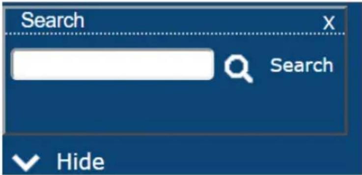
The meanings of the choices are explained in the following table:
| Choices Explanation | |
| Search | If you key in a search string and click Search, only port names that match the search string display in the tree. Wildcards (? for single characters; * for multiple characters) and the keyword or are supported, so that more than one port can show up in the list.For example:1. If you key in Web*, both Web Server 1 and Web Server 2 show up in the list.2. If you key in W*1 or M*2, both Web Server 1 and Mail Server 2 show up in the list. |
Connections
The main panel on the Connections page displays the Port List. From here you can select and connect to the serial devices via the port they are connected to.
| Port Number | Port Name | Status | Busy | Operating Mode | Operation | Port | ||
| [01] | COM1 | - | - | Console Management | Tainet | SSH | Dump Buffer | 5001/5101 |
| [02] | COM2 | - | - | Console Management | SSH | Dump Buffer | -/5102 | |
| [03] | COM3 | - | - | Console Management | SSH | Dump Buffer | -/5103 | |
| [04] | COM4 | - | - | Console Management | SSH | Dump Buffer | -/5104 | |
| [05] | COM5 | - | - | Console Management | SSH | Dump Buffer | -/5105 | |
| [06] | COM6 | - | - | Console Management | SSH | Dump Buffer | -/5106 | |
| [07] | COM7 | - | - | Console Management | SSH | Dump Buffer | -/5107 | |
| [08] | COM8 | - | - | Console Management | SSH | Dump Buffer | -/5108 | |
| [09] | COM9 | - | - | Console Management | SSH | Dump Buffer | -/5109 | |
| [10] | COM10 | - | - | Console Management | SSH | Dump Buffer | -/5110 | |
| [11] | COM11 | - | - | Console Management | SSH | Dump Buffer | -/5111 | |
| [12] | COM12 | - | - | Console Management | SSH | Dump Buffer | -/5112 | |
| [13] | COM13 | - | - | Console Management | SSH | Dump Buffer | -/5113 | |
| Heading Description | |
| Port Number This column represents the physical port that the device is connected to on the rear of the Serial Console Server. | |
| Port Name This column shows the port name which can be changed from the Port Access - Properties page (See page 70 for details). | |
| Status | This column shows the On or Off status of a device connected to the port. If no device is connected to the port a “-” will appear. |
| Busy | This column will show Busy when the port is being accessed by a user through the Serial Console Server. |
| Operation Mode | This column lists the Work Mode that the port is set to for access. The most common setting is Console Management, which is set on the Port Access - Properties page, under the Operation Mode tab (See Operating Mode, page 73 for details).Note: Console Management is the means of accessing a serial device for operations on it. |
| Operation | Lists Console Management access methods: Telnet and SSH for managing a port device. Clicking either one opens the SNViewer application to manage that serial device (See Telnet/SSH, page 63, below). Dump Buffer: This button allows you to dump and view the buffer log of activity conducted on the device. Click to save the log. (See Save & Copy, page 71 for details). |
| Port Shows the respective Telnet and SSH Port number configured for access to the serial device (See Service Ports, page 101 for details). | |
Telnet/SSH
To access a serial device connected to the Serial Console Server, click the port's Telnet or SSH button from the Port Access - Connections page:
![Port List Port Number Port Name Status Busy Operating Mode Operation Port [01] COM1 - - Console Management Tenest: SSH Dump Buffer 001/101 [02] COM2 - - Console Management SSH Dump Buffer -/$102 [03] COM3 - - Console Management SSH Dump Buffer -/$103 [04] COM4 - - Console Management SSH Dump Buffer -/$104 [05] COM5 - - Console Management SSH Dump Buffer -/$105 [06] COM6 - - Console Management SSH Dump Buffer -/$106 [07] COM7 - - Console Management SSH Dump Buffer -/$107 [08] COM8 - - Console Management SSH Dump Buffer -/$108 [09] COM9 - - Console Management SSH Dump Buffer -/$109 [10] COM10 - - Console Management SSH Dump Buffer -/$110 [11] COM11 - - Console Management SSH Dump Buffer -/$111 [12] COM12 - - Console Management SSH Dump Buffer -/$112 [13] COM13 - - Console Management SSH Dump Buffer -/$113 ATEN International Co., Ltd. All rights reserved.](/content/2026/06/1204310/images/e1709ba3995dbcfb83c5fe8c8b4e86c1347812978709f823c2508351d6dcd415.jpg)
The Serial Console Server opens SNViewer to start your session with the serial device, and a screen similar to the one below appears:
![Welcome to ALTUSEN SN0146 Copyright (c) 2009-2012 ATEN International Co., Lt Login: administrator Password: Connected to Port: 1 Press [Ctrl+ d] to go to the Suspend Menu.](/content/2026/06/1204310/images/b7a1f38ec14e971f10ec10895fb05a71f6ee0632c04b339dbdd250c79f488d1d.jpg)
From the SNViewer can you login and perform management activities on the serial device. For more information on using the SNViewer, see SNViewer, page 47 for details.
Port Attributes
Clicking a device on the sidebar from the Port Access - Connections page brings up the Port Attributes page with detailed information about the device and Power Over the Net™ reboot options, as shown here:
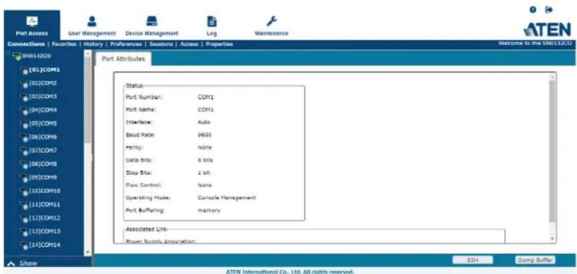
From here you can use the Telnet, SSH, and Dump Buffer buttons at the bottom of the page.
Favorites
The Favorites tab allows you to keep all the connections that you access most frequently in one convenient place. To add a port to Favorites, right-click on it from the sidebar and select Add to Favorites, or select a port and click Add. The layout and functions available on the Favorites tab are exactly the same as those found on the Port List tab (See Connections, page 62 for details).
![Favorites ID Port Number Port Name Status Busy Operating Mode Operation 01 [01] COM1 - - Console Management SSH Dump Buffer 02 [02] COM2 - - Console Management SSH Dump Buffer 03 [03] COM3 - - Console Management SSH Dump Buffer Add Delete](/content/2026/06/1204310/images/30d075a626a4bcf2081282131ed1680ccc3bdbaa72691de82dd450409a576c6f.jpg)
History
The History page provides a record of each time that a port was accessed. It provides quick access to the most recently used ports. You can access a port shown in the main panel by clicking it's Telnet or SSH button.
![History Port Number Port Name Status Bus# Operating Mode Time Operation [04] COM4 - - Console Management 10/30/2018 20:50:01 SSH Dump Buffer [03] COM3 - - Console Management 10/30/2018 20:50:04 SSH Dump Buffer [06] COM8 - - Console Management 11/16/2018 14:25:54 SSH Dump Buffer [07] COM7 - - Console Management 11/16/2018 14:26:06 SSH Dump Buffer [01] COM1 On - Real COM Port 12/24/2018 19:06:09 Dump Buffer [02] COM2 On - Console Management 12/26/2018 14:13:14 Talnat SSH Dump Buffer Delete](/content/2026/06/1204310/images/90f0b81e6e1be7611993e07df1d9cdd06755899f925cc8768364bbd3383a4485.jpg)
- If there are more entries than there is room on the screen, a scroll bar appears to let you scroll up and down to see the entire record.
- To clear the record, click the Delete button at the bottom right of the page.
- You can change the sort order by clicking the column headings.
Preferences
The Preferences page allows users to set up their own, individual, working environments. The Serial Console Server stores a separate configuration record for each user profile, and sets up the working configuration according to the Username that was keyed into the Login dialog box:
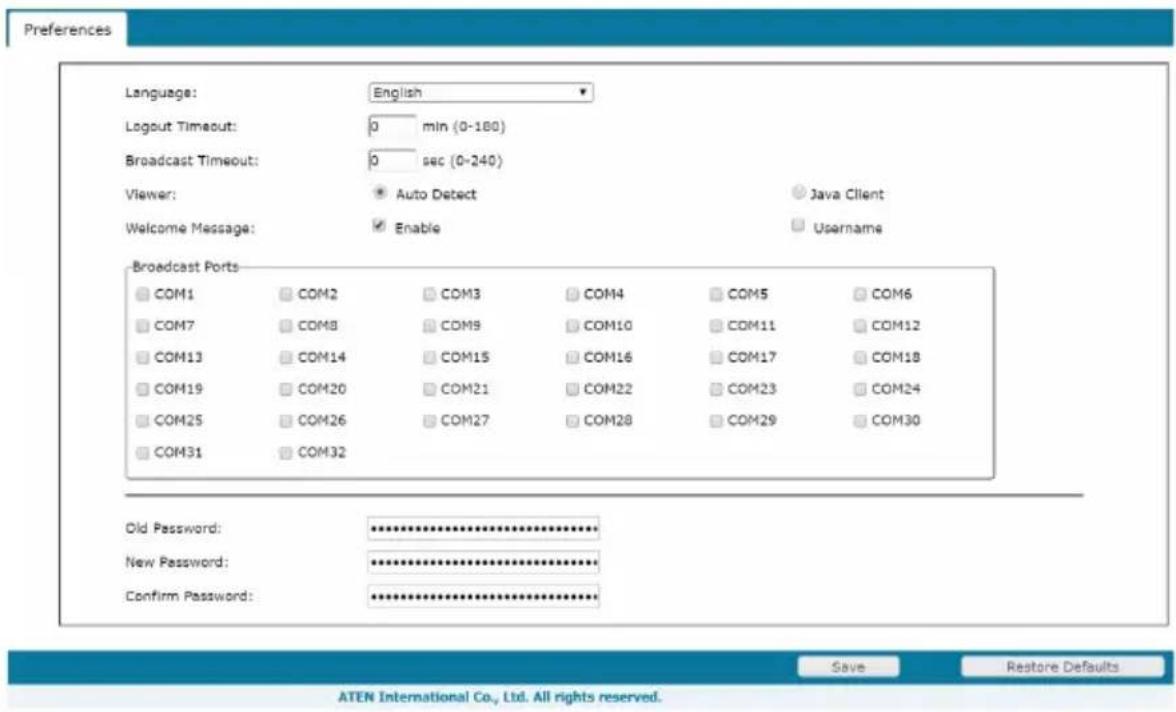
The page settings are explained in the following table:
| Setting Function | |
| Language Select the | language that the web GUI uses. |
| Logout Timeout If there is no user input for the amount of time set with this function, the user is automatically logged out. Once logged out, a login is necessary before the Serial Console Server can be accessed again. | |
| Broadcast Timeout If there is no user input for the amount of time set here, the Broadcast function is automatically ended. Key in a value from 0–240 seconds. A setting of 0 (zero) has the same effect as disabling the function.For more information on the Broadcast function, see Broadcast Ports within this table. | |
| Viewer You can choose which viewer is used when accessing a serial device:◆ Auto Detect will select the appropriate viewer based on the web browser used; WinClient for Windows Internet Explorer, Java Client for other web browsers (ex. Firefox).◆ Java Client will open the Java based viewer regardless of the web browser being used. | |
| Setting Function | |
| Welcome Message | You can choose to hide or show the Welcome Message and/or User Name displayed in the submenu bar. The default is disabled. |
| Broadcast Ports Select | the ports to receive broadcast commands by selecting the boxes. Selecting Broadcast Ports allows you to access and make changes on a single port and the same change will be made across all Broadcast Ports.Note: For broadcasting to work, you must access a Broadcast Port using the SNViewer and turn Broadcast on from the Control Panel (See Control Panel Functions, page 48). |
| Save Click Save to save any changes made to the Preferences settings. | |
| Changing a Password | ♦ In the Browser GUI, to change a user's password, key in the old password and new password into their input boxes; key the new password into the Confirm input box, then click Change Password to apply the change. |
Sessions
The Session page lets the administrator and users with User Management permissions see at a glance which users are currently logged into the Serial Console Server, and provides information about each of their sessions.
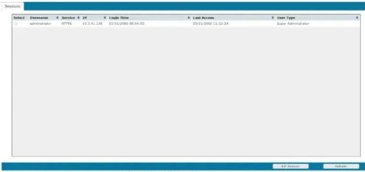
Note: 1. The Session page is not available for ordinary users.
-
Users with User Management permissions can only see the sessions of ordinary users.
-
The sort order of the information displayed can be changed by clicking the column headings.
The meanings of the headings at the top of the page are fairly straightforward.
| Heading Description | |
| Username Refers to the user that logged in. | |
| Service Displays the type of session (HTTP, HTTPS) established to log in. | |
| IP Refers to the IP address that the user has logged in from. | |
| Login Time Indicates the date and time the user logged in. | |
| Last Access Indicates when the user last accessed the system for use. | |
| User Type Lists the type of user who has logged in: SA (Super Administrator), Administrator (Administrator), or Normal user (User). |
This page also gives the administrator the option of forcing a user logout by checking the Select box for the user and clicking Kill Session at the bottom of the main panel.
Access
Administrators use the Access page to set user and group access and configuration rights for Serial Console Server ports and PDU devices. The Access page only appears for those users with User Management permissions and is not available for other users. Access rights can be set on a user-by-user or a group-by-group basis. See User Management, page 81, to setup groups and users.
![Port Access User Management Device Management Log Maintenance Connections | Favorites | History | Preferences | Sessions | Access | Properties SN9116CD [01]COM1 [02]COM2 [03]COM3 [04]COM4 [05]COM5 [06]COM6 [07]COM7 [08]COM8 [09]COM9 [10]COM10 [11]COM11 [12]COM12 [13]COM13 [14]COM14 Show User Access Group Access Users No Access View Only Full Access Config Power Supply hanrykuo * * * * jacksanweng * * * * jassanhui * * * jessicachan * * * maggidku ATEN International Co., Ltd. All rights reserved.](/content/2026/06/1204310/images/2f2a0eeec0c7b703a3af97ba3637e2e9b3c134a505a1aca0211a5ca0d859d7a3.jpg)
![Port Access User Management Device Management Log Maintenance Connections | Favorites | History | Preferences | Sessions | Access | Properties SN9116CD [01]COM1 [02]COM2 [03]COM3 [04]COM4 [05]COM5 [06]COM6 [07]COM7 [08]COM8 [09]COM9 [10]COM10 [11]COM11 [12]COM12 [13]COM13 [14]COM14 User Access Group Access Groups No Access View Only Full Access Config Power Supply OperatorA * # OperatorB * # OperatorC * # Save ATEN International Co., Ltd. All rights reserved.](/content/2026/06/1204310/images/eccf993cc6820c33b01cad4fb4bda3da3453c874518c28e659cc7f946835cc79.jpg)
Use the radio buttons to configure access rights on the User Access and Group Access page. The meaning of the columns are given in the table, below:
| User Access Each User created on the Serial Console Server (excluding Super Administrator accounts) is listed to set access and configuration rights for each device listed on the sidebar. Select a device from the Sidebar to set the access and configuration rights of each User. | ||
| Group Access Each Group created on the Serial Console Server is listed to set access and configuration rights for each device listed on the sidebar. Select a device from the Sidebar to set the access and configuration rights of each Group. | ||
| Access Rights The Access columns are where access rights are set. The meaning of each is explained below. | ||
| Config Sets or denies permission for the user to make changes to a port's configuration settings. A check mark(√) indicates that the user has permission; an empty box means that the user does not have permission. | ||
| Power Supply This column permits/restricts the configuration and power operation of ports that have Power Over the NetTM devices connected to them. A check mark(√) indicates that the user has permission; an empty box means that the user does not have permission. |
Properties
When you click the Properties tab, the Port Settings List page appears:
| Port Number | Port Name | Operating Mode | Properties |
| [01] | COM1 | Console Management | 96.00,N.B.1,None |
| [02] | COM2 | Console Management | 96.00,N.B.1,None |
| [03] | COM3 | Console Management | 96.00,N.B.1,None |
| [04] | COM4 | Console Management | 96.00,N.B.1,None |
| [05] | COM5 | Console Management | 96.00,N.B.1,None |
| [06] | COM6 | Console Management | 96.00,N.B.1,None |
| [07] | COM7 | Console Management | 96.00,N.B.1,None |
| [08] | COM8 | Console Management | 96.00,N.B.1,None |
| [09] | COM9 | Console Management | 96.00,N.B.1,None |
| [10] | COM10 | Console Management | 96.00,N.B.1,None |
| [11] | COM11 | Console Management | 96.00,N.B.1,None |
| [12] | COM12 | Console Management | 96.00,N.B.1,None |
| [13] | COM13 | Console Management | 96.00,N.B.1,None |
| [14] | COM14 | Console Management | 96.00,N.B.1,None |
| [15] | COM15 | Console Management | 96.00,N.B.1,None |
| [16] | COM16 | Console Management | 96.00,N.B.1,None |
| [17] | COM17 | Console Management | 96.00,N.B.1,None |
| [18] | COM18 | Console Management | 96.00,N.B.1,None |
| [19] | COM19 | Console Management | 96.00,N.B.1,None |
| [20] | COM20 | Console Management | 96.00,N.B.1,None |
| [21] | COM23 | Console Management | 96.00,N.B.1,None |
| [22] | COM22 | Console Management | 96.00,N.B.1,None |
| [23] | COM23 | Console Management | 96.00,N.B.1,None |
| [24] | COM24 | Console Management | 96.00,N.B.1,None |
When a port is double clicked from the Port Settings List or from the Sidebar, the Properties page appears and looks similar to the one below:
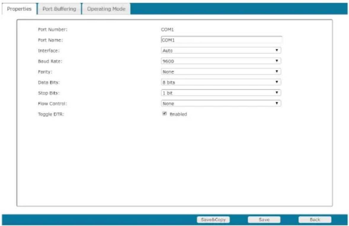
This panel allows you to make configuration settings for the selected port, as explained in the table below:
| Setting Meaning |
| Port ID Each port on the Serial Console Server has a port ID number. The value in this field indicates the port that is being configured. |
| Setting Meaning | |
| Port Name | You can give a port an appropriate name by editing the Port Name field. |
| Interface | Choose between Auto (default), DTE or DCE. |
| Baud Rate | This sets the port's data transfer speed. Choices are from 300–230400 (drop down the list to see all options). Set this to match the baud rate setting of the connected device. Default is 9600 (which is a default setting for many serial devices). |
| Data Bits This sets the number of bits used to transmit one character of data.Choices are: 5, 6, 7 and 8. Set this to match the data bit setting of the connected device. Default is 8 (which is a default setting for many serial devices). | |
| Parity This bit checks the integrity of the transmitted data. Choices are: None; Odd; Even. Set this to match the parity setting of the connected device. Default is None (which is a default setting for many serial devices). | |
| Stop Bits This indicates that a character has been transmitted. Set this to match the stop bit setting of the connected device. Choices are: 1, 1.5, and 2. Default is 1 (which is a default setting for many serial devices). | |
| Flow Control This allows you to choose how the data flow will be controlled.Choices are: None, Hardware (RTS/CTS), and XON/XOFF. Set this to match the flow control setting of the connected device. Default is None. | |
| Toggle DTR Enabling this parameter allows the DTR signal to toggle between enabled and disabled. A check mark (√) enables Toggle DTR. | |
Save & Copy
At the bottom right side of each Properties page you can click Save to save the settings for the selected port, or Save&Copy which allows you to copy and save the current port settings for any/all other ports, as shown here:
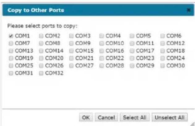
Simply select the ports you want to save the current setting to and click OK.
Port Buffering
Port Buffering creates a log of activity conducted when a port is accessed. You can save the log to memory on the Serial Console Server, or to a USB drive. A USB drive provides more storage space, while the Serial Console Server is limited to it's internal memory.
Note: USB drive is only supported on SN01xxCO models.
To enable Port Buffering, from the drop-down menu: select Memory, NFS, Syslog Server or select a mounted USB drive. Select Disable to disable Port Buffering. Use the check box to enable/disable Time Stamps.
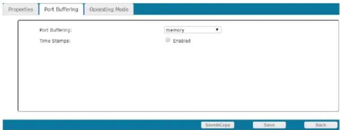
If you selected a mounted USB drive, addition information is provided:
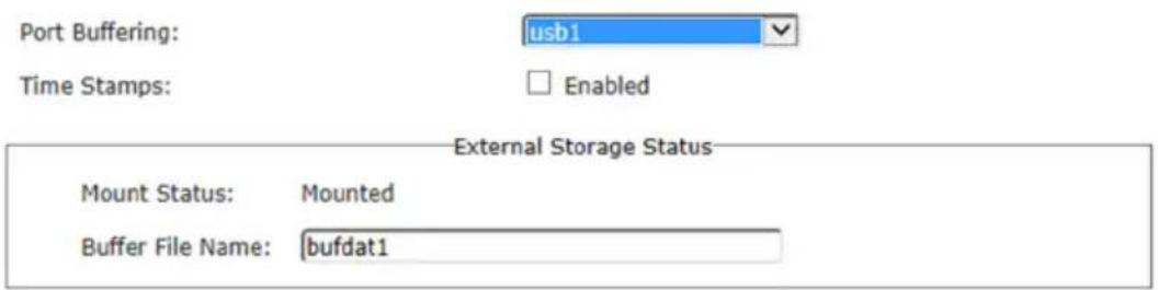
The Buffer File Name allows you to customize the file name of the log saved to the USB drive.
For more information on Syslog Server, NFS and mounted USB drive, please refer to Devices on page 97.
Operating Mode
The Operating Mode page allows you to configure settings for access and management of each port. This determines how each serial device is accessed via operating modes. For a detailed explanation of each Operating Mode, see Operating Mode, page 56
Operating Mode – This sets the mode you use to access the port device for management. The most common setting is Console Management, which allows for Telnet/SSH sessions from the Port Access - Connections page. Select the port’s work mode from the drop-down menu.
Note: See Port Operating Modes, page 55, for full details of the different port operating modes that are available from the drop-down list.
- Console Management
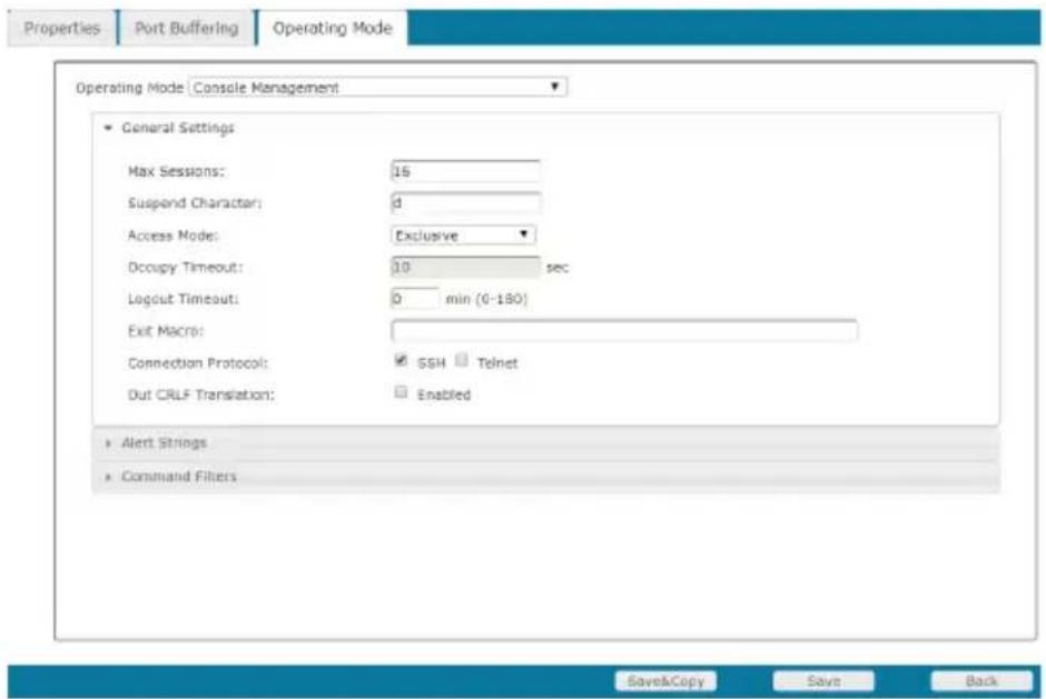
| Setting Meaning | |
| Max Sessions Set the maximum number of concurrent sessions here. | |
| Suspend Character | The Suspend character is used to bring up the Suspend Menu in Telnet sessions. Valid characters are A-Z, except H, I, J, and M - which may not be used. |
| Access Mode | Defines how the port is to be accessed when multiple users have logged on, as follows:Exclusive:The first user to access the port has exclusive control over the port. No other users can view the port. TheTimeoutfunction does not apply to ports which have this setting.Occupy:The first user to access the port has control over the port. However, additional users may view the port. If the user who controls the port is inactive for longer than the time set in theTimeoutbox, port control is transferred to the next user who makes a change on the system.Share:Users simultaneously share control over the port. Input from the users is placed in a queue and executed chronologically. |
| OccupyTimeout | If there is no input on this port for the amount of time set with this function, the port is released for use by another user. |
| LogoutTimeout | Some applications do not require a user to login and in such a situation theOccupyTimeoutsetting will not work since the timer is set according to the user's operations. In such a case, use the Logout Timeout option. With this feature, if there is no user input for the amount of time set, the user is automatically logged out. Once logged out, a login is necessary before the device can be accessed again. |
| Exit Macro Set | the Exit Macro here.You can create a macro that will execute when exiting the serial device. |
| ConnectionProtocol | Use the check boxes to enable/disable SSH and Telnet connection protocols. |
| CRLFTranslation | This allows you to select whether to send a Carriage Return and Line Feed signal (CRLF). |
Alert Strings
The Port Alert Strings dialog box provides a way for you to be informed about problems that occur on the devices connected to the Serial Console Server's ports.
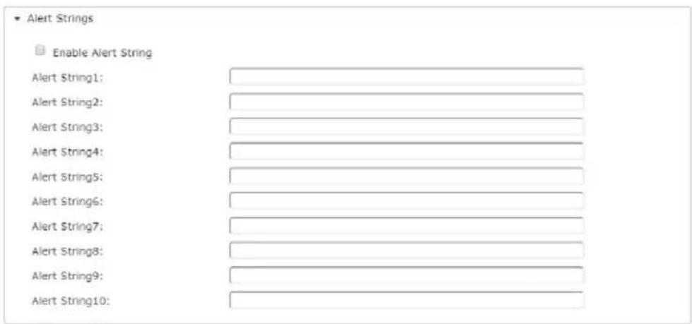
When a device has a problem – such as a critical error that requires a reboot, or an SNMP Trap event has been triggered – debug messages can be sent through its serial port to the Serial Console Server's COM port.
When the Serial Console Server receives such a message, it can send an SNMP Trap alert and/or an email to inform the user specified here of the problem. You can specify up to 10 types of alerts.
After setting up this page, whenever one of the specified alerts is generated, you will be informed of its occurrence.
Command Filters
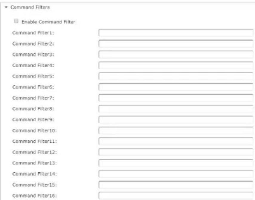
On this page you can specify up to 16 command filters.
Real COM Port
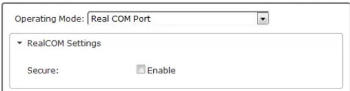
Check Enable to encrypt all data being transferred through the session.
TCP Server
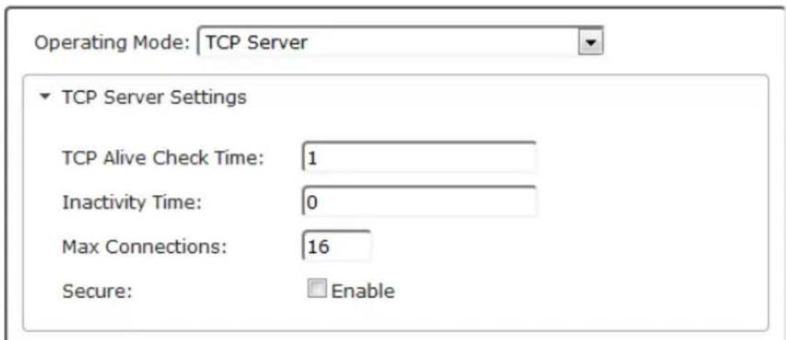
| Setting | Meaning |
| TCP Alive Check Time | This setting defines how often the Serial Console Server should check the TCP socket connection to the host computer to determine whether it is up, or if it has gone down. Enter the number of minutes the Serial Console Server should wait before checking the TCP connection to the host computer. |
| Inactivity Time | This setting defines how long to wait when there is no data transferred between the Serial Console Server and host computer before the connection drops. Enter the number of minutes that can pass before the Serial Console Server drops the connection. |
| Max Connections | Enter the maximum number of concurrent connections allowed. The Serial Console Server can establish up to 16 connections simultaneously. |
| Secure | Check Enable to encrypt all data being transferred through the session. |
TCP Client
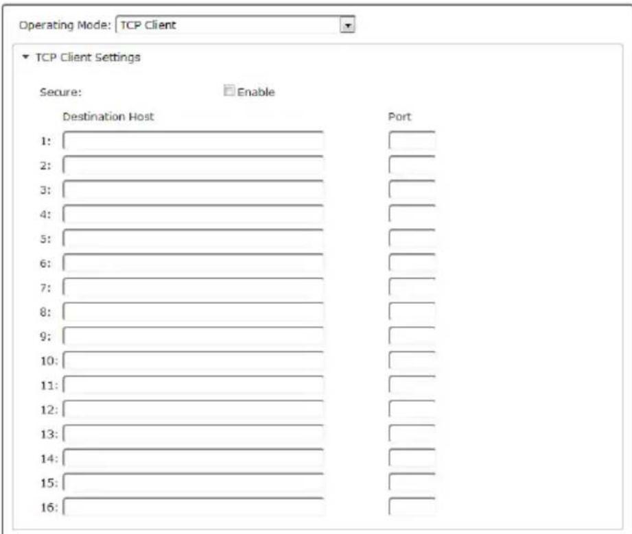
| Setting Meaning | |
| Secure | Check Enable to encrypt all data being transferred through the session. |
| Destination Host / Port | Key-in the IP address and service port of Destination Host or another Serial Console Server (TCP Server) to create a serial tunnel for transmitting the data by between. The Serial Console Server can send data to up to 16 host computers simultaneously. |
◆ UDP Mode

| Setting | Meaning |
| Host Start IP / Host End IP and Port | Use this setting to establish connections via the UDP protocol. Enter a single or range of IP addresses and the TCP/IP port number. |
Virtual Modem
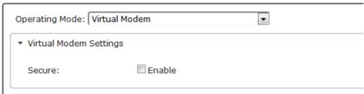
Check Enable to encrypt all data being transferred through the session.
- Console Management Direct
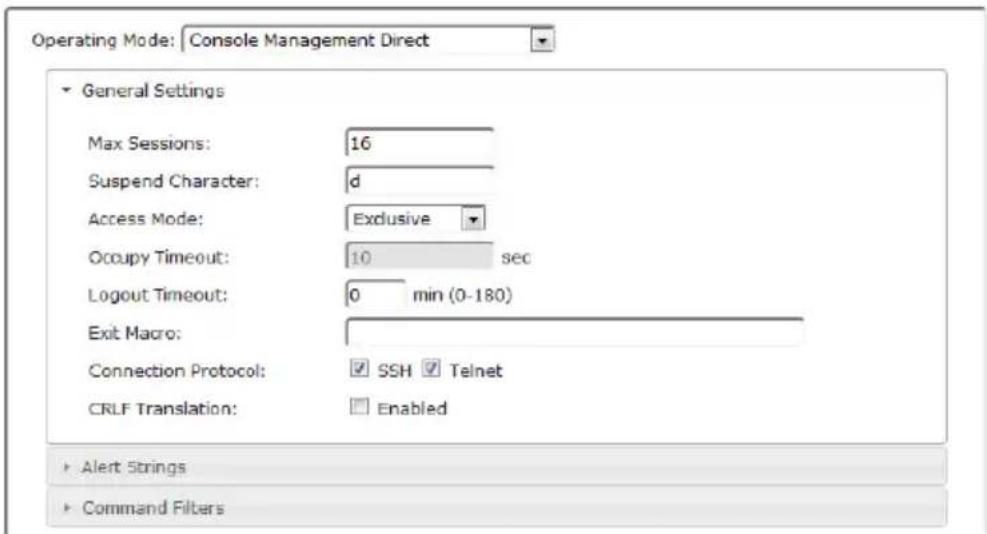
| Setting Meaning | |
| Max Sessions Set the maximum number of concurrent sessions here. | |
| Suspend Character | The Suspend character is used to bring up the Suspend Menu in Telnet sessions. Valid characters are A-Z, except H, I, J, and M - which may not be used. |
| Access Mode Defines how the port is to be accessed when multiple users have logged on, as follows:Exclusive: The first user to access the port has exclusive control over the port. No other users can view the port. The Timeout function does not apply to ports which have this setting.Occupy: The first user to access the port has control over the port. However, additional users may view the port. If the user who controls the port is inactive for longer than the time set in the Timeout box, port control is transferred to the next user who makes a change on the system.Share: Users simultaneously share control over the port. Input from the users is placed in a queue and executed chronologically. | |
| Occupy Timeout | If there is no input on this port for the amount of time set with this function, the port is released for use by another user. |
| Logout Timeout | Some applications do not require a user to login and in such a situation the Occupy Timeout setting will not work since the timer is set according to the user's operations. In such a case, use the Logout Timeout option. With this feature, if there is no user input for the amount of time set, the user is automatically logged out. Once logged out, a login is necessary before the device can be accessed again. |
| Exit Macro Set the Exit Macro here.You can create a macro that will execute when exiting the serial device. | |
| Connection Protocol | Use the check boxes to enable/disable SSH and Telnet connection protocols. |
| Setting | Meaning |
| CRLF Translation | This allows you to select whether to send a Carriage Return and Line Feed signal (CRLF). |
For information regarding the Alert Strings and Command Filters, see page 74.
◆ Disabled
Select this option to disable use of the serial port on the Serial Console Server.
Chapter 7
User Management
Overview
When you select the User Management tab the screen comes up with the Accounts page displayed:
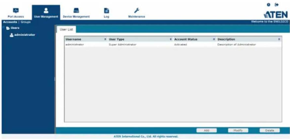
The page is organized into two main areas: the Sidebar at the left, and the large main panel at the right.
- Users and groups appear in the panel at the left of the page. The large panel at the right provides more detailed information at-a-glance for each.
- The Browser GUI has separate menu bar entries for Accounts (Users) and Groups. Depending on the menu item selected, either Users or Groups are listed in the Sidebar.
- In the Browser GUI, the sort order of the information displayed can be changed by clicking the main panel column headings.
- The buttons below the main panel are used to manage users and groups, as shown in the sections that follow.
Users
The Serial Console Server supports three user types, as shown in the table bellow:
| User Type Role | |
| Super Administrator Access and manage ports and devices. Manage Users, and Groups. Configure the overall installation. Configure personal working environment. | |
| Administrator Access and manage authorized ports and devices. Manage Users and Groups. Configure personal working environment. | |
| User Access authorized ports and devices. Manage authorized ports and devices; configure personal working environment.Note: Users who have been given permission to do so, may also manage other users. | |
Adding Users
To add a user, and assign user permissions, do the following:
- Select Users in the Sidebar.
- Click Add at the bottom of the main panel. The User notebook opens, with the User tab selected:
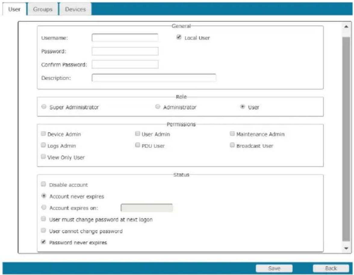
- Enter the required information in the appropriate fields. A description of each of the fields is given in the table below:
| Field Description | |
| Username From 1 to | 16 characters are allowed depending on the Account Policy settings. See Account Policy, page 123. |
| Password From 0 to | 16 characters are allowed depending on the Account Policy settings. See Account Policy, page 123. |
| Confirm Password To | be sure there is no mistake in the password, you are asked to enter it again. The two entries must match. |
| Description Additional | information about the user that you may wish to include. |
| Role There are three | categories: Super Administrator, Administrator and User. There is no limitation on the number of accounts that can be created in each category.◆ The Super Administrator is responsible for the overall installation configuration and maintenance; user management; and device and port assignments. The Super Administrator's permissions are automatically assigned by the system and cannot be altered.◆ The Administrators default permissions include everything except Device Admin and User Admin, but the permissions can be altered for each Administrator by checking or unchecking any of the permissions checkboxes.◆ The Users default permissions include PDU User and Broadcast User, but the permissions can be altered for each User by checking or unchecking any of the permissions checkboxes. |
| Permissions | ◆ Enabling Device Admin allows a user to configure and control the settings for overall Serial Console Server operations (see Device Management, page 97).◆ Enabling User Admin allows a user to create, modify, and delete user and group accounts.◆ Enabling Maintenance Admin allows a user to perform all the Maintenance operations available under the Maintenance tab (see Maintenance, page 131).◆ Enabling Logs Admin allows a user to access the system log (see Log, page 127).◆ Enabling PDU User allows users to configure Power Over the NetTM devices◆ Enabling Broadcast User allows the use of Broadcasting◆ Enabling View Only User limits users to only being able to view the display of connected devices. They cannot control port access, nor can they input any keyboard or mouse signals to the devices they view. |
| Status Status allows you to control the user's account and access to the installation, as follows:◆ Disable Account lets you suspend a user's account without actually deleting it, so that it can be easily reinstated in the future.◆ If you don't want to limit the time scope of the account, select Account never expires; if you do want to limit the amount of time that the account remains in effect, select Account expires on, and key in the expiration date.◆ To require a user to change his password at the next logon, select User must change password at next logon. This can be used by the administrator to give the user a temporary password to log in for the first time, and then let the user set the password of his choice for future logins.◆ To make a password permanent, so that the user cannot change it to something else, select User cannot change password.◆ For security purposes, administrators may want users to change their passwords from time to time.◆ If not, select Password never expires. This allows users to keep their current passwords for as long as they like.◆ If so, select Password expires after, and key in the number of days allowed before the password expires. Once the time is up, a new password must be set. | |
- At this point you can assign the new user to a group by selecting the Groups tab – the Groups page is discussed on page 89. You can also assign the user's port access rights by selecting the Devices tab – the Devices page is discussed on page 94.
Note: Optionally, you can skip this step now to add more users and create groups, and come back to it later.
- When your selections have been made click Save.
-
When the Operation Succeeded message appears, click OK.
-
Click Users in the Sidebar to return to the main screen. The new user appears in the Sidebar list and in the main panel, as well.
-
The Sidebar Users list can expand and collapse. If the list is expanded, click the minus symbol (−) next to the Users icon to collapse it; if it is collapsed there is a plus symbol (+) next to the icon. Click the plus symbol to expand it.
- The icon for super administrators has two black bands; the icon for administrators has one red band.
- The large main panel shows the user’s name; the description that was given when the account was created; and whether the account is currently active or has been disabled.
Modifying User Accounts
To modify a user account, do the following:
- In the Sidebar User list, click the user's name
- or -
In the main panel, select the user's name
-
Click Modify.
-
In the User page that comes up, make your changes, then click Save.
Note: The User page is discussed on page 82; the Groups page is discussed on page 89, the Devices page is discussed on page 94.
Deleting User Accounts
To delete a user account do the following:
- In the main panel, select the user's name.
- Click Delete.
- Click OK.
Groups
Groups allow administrators to easily and efficiently manage users and devices. Since device access rights apply to anyone who is a member of the group, administrators need only set them once for the group, instead of having to set them for each user individually. Multiple groups can be defined to allow some users access to specific devices, while restricting other users from accessing them.
Creating Groups
To create a group, do the following:
- Select Groups on the menu bar.
- Click Add at the bottom of the main panel. The Group notebook opens, with the Group tab selected:
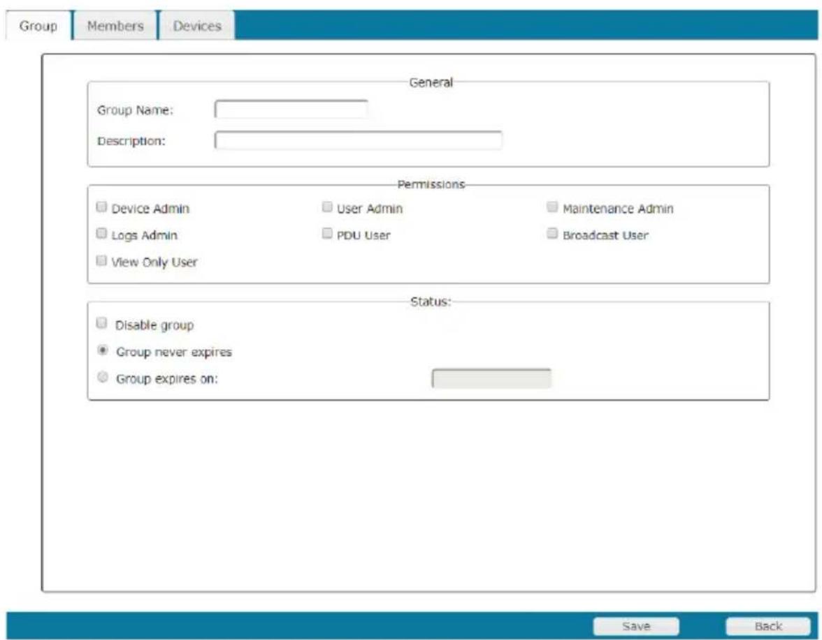
- Enter the required information in the appropriate fields. A description of each of the fields is given in the table below:
| Field Description | |
| Group Name A maximum of | 16 characters is allowed. |
| Description Additional information about the user that you may wish to include. A maximum of 63 characters is allowed. | |
| Permissions Permissions and restrictions for groups are set by checking the appropriate boxes. These are the same permissions as the ones specified for Users. See Permissions, page 83 for details | |
- At this point you can assign users to the group by selecting the Members tab – the Members page is discussed on page 92. You can also assign the group's port access rights by selecting the Devices tab – the Devices page is discussed on page 94.
Note: Optionally, you can skip this step now to add more groups and assign users to them, and come back to it later.
-
When your selections have been made click Save.
-
When the Operation Succeeded message appears, click OK.
-
Click Group in the Sidebar to return to the main screen. The new group appears in the Sidebar Group list and in the main panel.
- The Sidebar Group list can expand and collapse. If the list is expanded, click the minus symbol (−) next to the Users icon to collapse it; if it is collapsed there is a plus symbol (+) next to the icon. Click the plus symbol to expand it.
- The large main panel shows the group’s name, and the description that was given when the group was created
Repeat the above procedure to add additional groups.
Note: You must perform Step 7 before attempting to add a new group, or else the new group you are creating will replace the group you just finished creating.
Modifying Groups
To modify a group, do the following:
- In the Sidebar Group list, click the group's name
- or -
In the main panel, select the group's name.
-
Click Modify.
-
In the Group notebook that comes up, make your changes, then click Save.
Note: The Group page is discussed on page 86; the Members page is discussed on page 92, The Devices page is discussed on page 94.
Deleting Groups
To delete a group do the following:
- In the Sidebar, click the Groups icon.
- In the main panel, select the group's name.
- Click Delete.
- Click OK.
Users and Groups
There are two ways to manage users and groups: from the Users notebook; and from the Group notebook.
Note: Before you can assign users to groups, you must first create them. See Adding Users, page 82 for details.
Assigning Users to a Group From the User's Notebook
To assign a user to a group from the User's notebook, do the following:
- In the Sidebar User list, click the user's name
- or -
In the main panel, select the user's name
-
Click Modify.
-
In the User notebook that comes up, select the Groups tab. A screen, similar to the one below, appears:
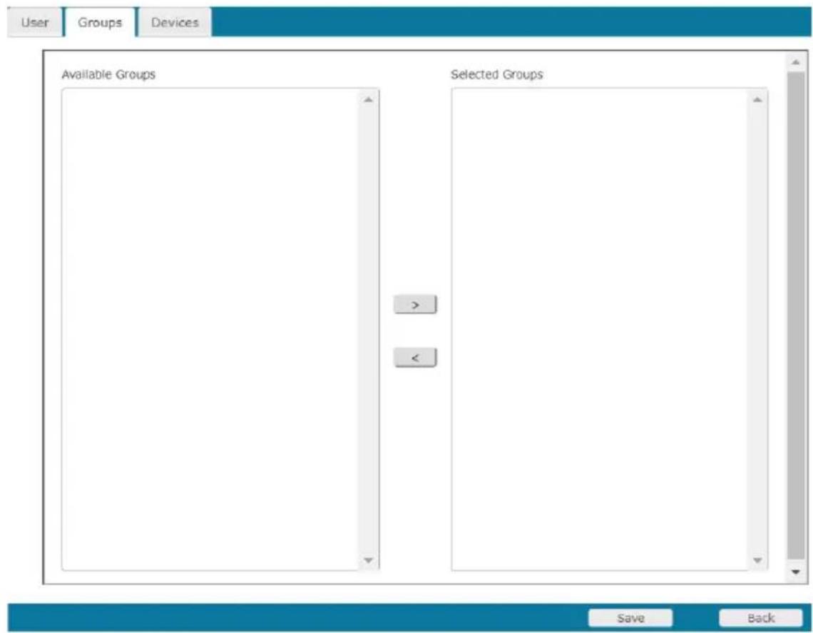
-
In the Available column, select the group that you want the user to be in.
-
Click the Right Arrow to put the group's name into the Selected column.
-
Repeat the above for any other groups that you want the user to be in.
- Click Save when you are done.
Note: If a user has permissions in addition to the ones assigned to the group, the user keeps those permissions in addition to the group ones.
Removing Users From a Group From the User's Notebook
To remove a user from a group from the User's notebook, do the following:
- In the Sidebar User list, click the user's name
- or -
In the main panel, select the user's name.
-
Click Modify.
-
In the User notebook that comes up, select the Groups tab. A screen, similar to the one below, appears:

-
In the Selected column, select the group that you want to remove the user from.
-
Click the Left Arrow to remove the group's name from the Selected column. (It goes back into the Available column.)
-
Repeat the above for any other groups that you want to remove the user from.
-
Click Save when you are done.
Assigning Users to a Group From the Group's Notebook
To assign a user to a group from the Group notebook, do the following:
- In the Sidebar Group list, click the group's name
- or -
In the main panel, select the group's name.
- Click Modify.
- In the Group notebook that comes up, select the Members tab. A screen, similar to the one below, appears:
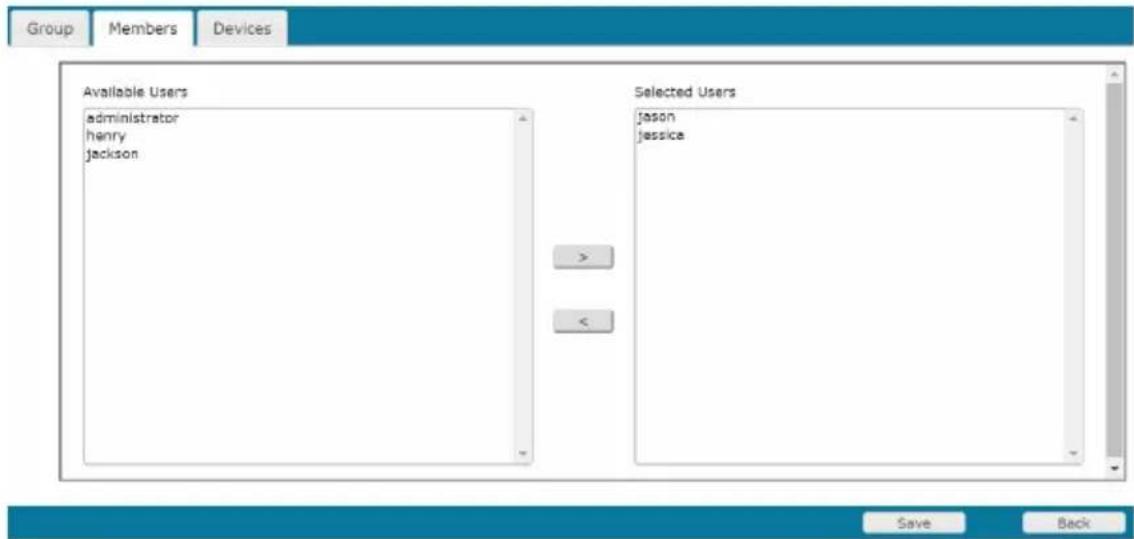
- In the Available column, select the user that you want to be a member of the group.
- Click the Right Arrow to put the user's name into the Selected column.
- Repeat the above for any other users that you want to be members of the group.
- Click Save when you are done.
Note: If a user has permissions in addition to the ones assigned to the group, the user keeps those permissions in addition to the group ones.
Removing Users From a Group From the Group's Notebook
To remove a user from a group from the Group's notebook, do the following:
- In the Sidebar Group list, click the group's name
-Or-
In the main panel, select the group's name.
-
Click Modify.
-
In the Group notebook that comes up, select the Members tab. A screen, similar to the one below, appears:
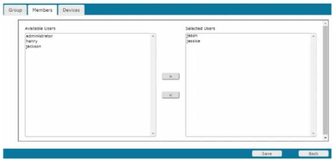
-
In the Selected column, select the user that you want to remove from the group.
-
Click the Left Arrow to remove the user's name from the Selected column. (It goes back into the Available column.)
-
Repeat the above for any other users that you want to remove from the group.
-
Click Save when you are done.
Device Assignment
When a user logs in to the Serial Console Server, the interface comes up with the Port Access page displayed. All the ports that the user is permitted to access are listed in the Sidebar at the left of the page. Access permissions for those ports and the devices connected to them are assigned on a port-by-port basis from the User or Group list on the Sidebar of the User Management page.
Assigning Device Permissions under User Settings
To assign a device permissions to a user from the User's notebook, do the following:
- In the Sidebar User list, click the user's name
-or-
In the main panel, select the user's name.
-
Click Modify.
-
In the User notebook that comes up, select the Devices tab. A screen, similar to the one below, appears:
![User Groups Devices Port Name No Access View Only Full Access Config Power Supply SN0132CO [01]COM1 # # # # # [02]COM2 # # # # [03]COM3 # # # # [04]COM4 # # # [05]COM5 # # # [06]COM6 # # # [07]COM7 # # # [08]COM8 # # # [09]COM9 # # # [10]COM10 # # # [11]COM11 # # # [12]COM12 # # # [13]COM13 # # # [14]COM14 # # # [15]COM15 # # # [16]COM16 # # # [17]COM17 # # # [18]COM18 # # [19]COM19 # # [20]COM20 # Save Back](/content/2026/06/1204310/images/7cc85ce7891a16e30aab836173cfad67c2c64129cdbb9c1fa9f506a8177eb975.jpg)
- Make your permission settings for each port according to the information provided below:
Name: Each port accessible to the user is listed under the Names column.
Access:
The Access column is where device access rights are set. Click the radio buttons in the rows that corresponds your choices. The meanings are described, below:
| Full Access | The user can view the remote screen and can perform operations on the remote server from his keyboard. |
| View Only | The user can only view the remote screen; he cannot perform any operations on it. |
| No Access | No access rights - the Port will not show up on the User's list on the Main Screen. |
Config:
The Config column is where a user's permission to make changes to a port's configuration settings are permitted/restricted. A check mark (√) indicates that the user has permission to make changes to the port's configuration settings; an empty box means that the user is denied permission to make configuration changes.
Power Supply: The Power Supply column permits/restricts the configuration and power operation of ports that have Power Over the Net ^™ devices connected to them. A check mark ( ) indicates that the user has permission; an empty box means that the user does not have permission.
Note: Reserved to be used with PG series PDU.
- When you have finished making your choices, click Save.
- In the confirmation popup that appears, click OK.
Note: In any of the columns, you can use Shift-Click or Ctrl-Click to select a group of ports to configure. Clicking to cycle through the choices on any one of the selected ports causes all of them to cycle in unison.
Assigning Device Permissions under Group Settings
To assign a device permissions to a Group of users, do the following:
- In the Sidebar Groups list, click the group's name
- or -
In the main panel, select the group's name.
- Click Modify.
- In the Groups notebook that comes up, select the Devices tab.
- The screen that comes up is the same one that appears in the User's notebook. The only difference is that whatever settings you make apply to all members of the group instead of just one individual member.
Make your device assignments according to the information described under Assigning Device Permissions under User Settings, page 94.
Devices
The Device Management page opens with the top level Serial Console Server selected in the Sidebar, with all its ports nested below, and the Device Information page displaying in the main panel:
![Device | Network | APPS | DOBC | Security | Association | Data/Time G013200 [06]COM1 [08]COM6 [08]COM5 [08]COM4 [08]COM5 [08]COM6 [07]COM7 [08]COM8 [08]COM9 [10]COM10 [11]COM11 [12]COM12 [13]COM13 [14]COM14 [15]COM15 [15]COM16 [17]COM17 [18]COM18 [19]COM19 [20]COM20 [20]COM21 Show Device Information General Device Name: GSS3.SUC3 Description: MPC: Network Interface: Source: MAC: 00157-M800VA qsv4 addr: 03.3.005.157, Mask:255.255.254.8 qsv4 addr: Mask: 200 @ DSS1 @ MSKAPL.LNC Power Supply Detection Power 1 Status: On Power 2 Status: Off PULFIRE Devices NPS Settings NPS Source NPS Name Status Auto Operation rml n% C# Mode1 rml7 n% C# Mode2 rml3 n% C# Mode3 rml4 n% C# Mode4 ATEN@ServiceCard Co., Ltd. All rights reserved.](/content/2026/06/1204310/images/5ad506de34d615f633670ab91916d71a268a3ce6d46966f6b5d83887d86996ac.jpg)
General
The General section of the Device Information page displays and allows you to set the Device Name and Description and view the Manufacturing (MFG) information of the Serial Console Server. The Network Interfaces section provides detailed information about it's network configurations.
Note: The “MFG Number” (Manufacturing Number) is an internal serial number used by ATEN’s factory and technical support staff to identify products. This number does not affect products’ warranty. If your product requires after-sales services, you may provide the MFG Number to ATEN’s sales or technical support staff to identify the product and model number.
The SN0108CO / SN0116CO / SN0132CO / SN0148CO are designed with two power supplies. The Power Supply Detection section provides information about the two Serial Console Server's power supplies.
- The icons for Power Supply 1 and Power Supply 2 display in gray when there is no power to the power supply - they display in blue when power is present.
- When the Power Supply Detection function is enabled (there is a check in the checkbox), when there is only one source of power, the Serial Console Server will beep to warn you of the problem. The default for this function is enabled.
If you are at the Local Console you will see a message asking you to confirm that your intention is to only have one power source. If your intention is to only have one source of power, there are two ways to stop the beeping:
1) You can disable power supply warnings by unchecking the checkbox. Do this if you want to disable this function on a permanent basis.
2) You can confirm your intention in the dialog box. Do this if you only want to disable the warning temporarily. With this method, the warning function will be back in effect after the next system reset.
Mounted Devices
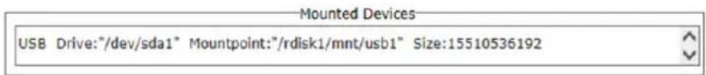
The Mounted Devices section displays information about USB and NFS storage devices connected for use. When a USB drive is plugged into the front of the Serial Console Server (SN0108CO / SN0116CO / SN0132CO / SN0148CO only), or NFS storage locations are set (see NFS Settings below), they appear here with detailed information about the mounted device.
NFS Settings
| NFS Settings | ||||
| NFS Name | Source | Status | Auto | Operation |
| nfs1 | N/A | ☐ | Mount | |
| nfs2 | N/A | ☐ | Mount | |
| nfs3 | N/A | ☐ | Mount | |
| nfs4 | N/A | ☐ | Mount | |
NFS (Network File System) allows you to mount storage devices across the network. You can mount up to 4 devices. Fill in the Source with the storage devices network location (IP Address or Network Name) including the full path of the location you want to mount. Next, click Mount to mount the NFS storage device. The Status column indicates N/A, Mounted, or Unmounted. Unmounted shows if the storage device is not accessible. If this happens make
sure the device is accessible on the network, and check that the Source information you typed in is correct. Check Auto to auto mount the NFS.
External USB Drive
| External USB Drive | |||
| USB Name | Source | Status | Operation |
| usb1 | USB3.0.FLASH DRIVE; Size: 15510536192 | Mounted | Unmount |
| usb2 | N/A | Mount | |
| usb3 | N/A | Mount | |
You can mount up to 3 external USB drives. Click Mount or Unmount to mount or unmount the drive. The Status column indicates N/A, Mounted, or Unmounted.
Syslog Settings for Port Logs
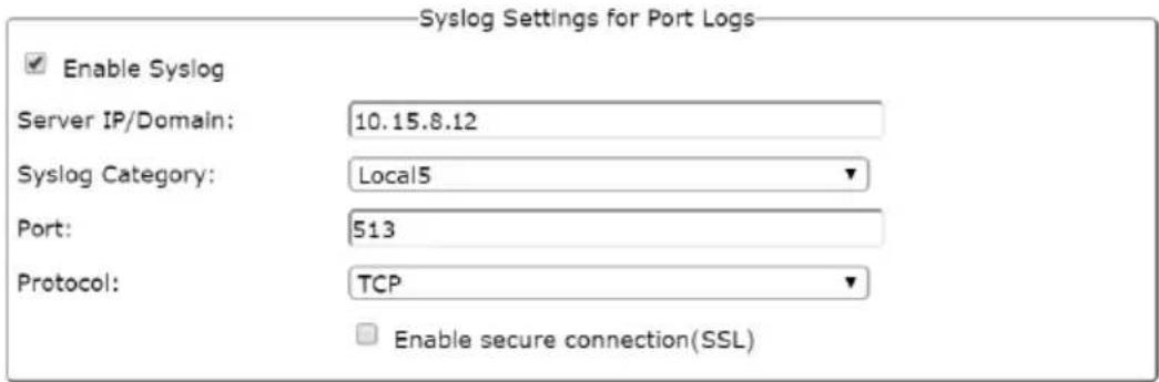
You can allow users to store logs on pre-defined Syslog servers.
To activate the function, check the “Enable Syslog” option to enable the function. When this function is activated, “Syslog server” option will then become available in the Port Buffering function.
Enter/select the server information in the fields shown in the diagram.
Network
The Network page is used to specify the network environment.
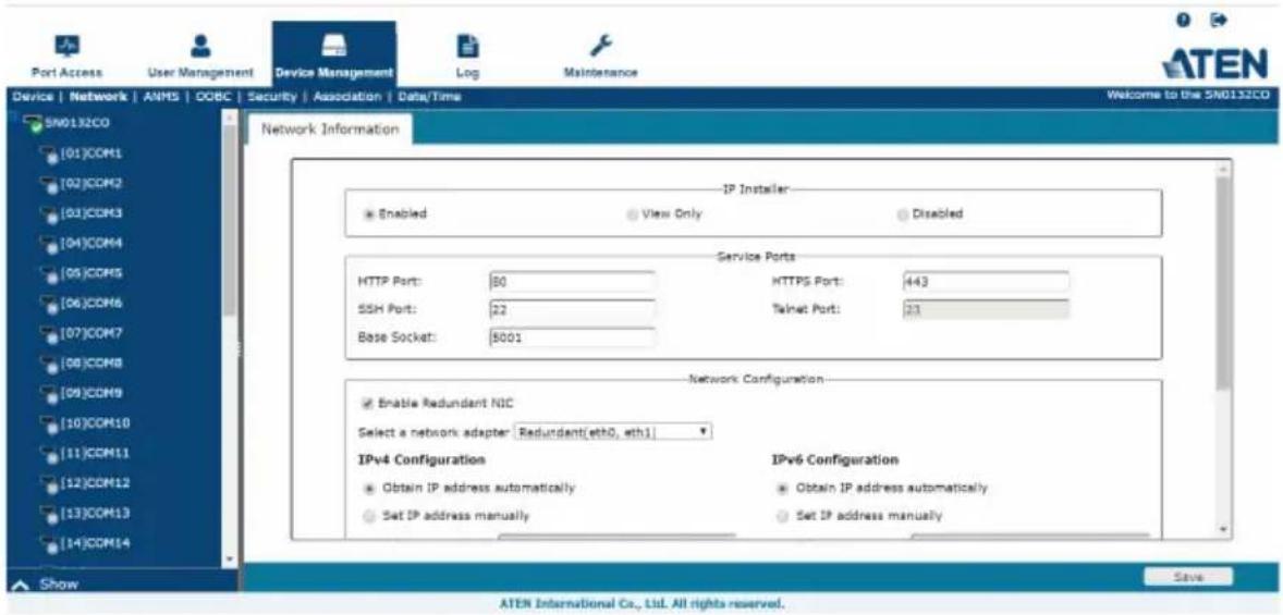
Each of the elements on this page is described in the sections that follow.
Note: The Enable Redundant NIC option is only available for SN0108CO / SN0116CO / SN0132CO / SN0148CO serial console servers.
IP Installer
The IP Installer is an external Windows-based utility for assigning IP addresses to the Serial Console Server.
Click one of the radio buttons to select Enable, View Only, or Disabled for the IP Installer utility. See IP Installer, page 150, for IP Installer details.
Note: 1. If you select View Only, you will be able to see the Serial Console Server in the IP Installer's Device List, but you will not be able to change the IP address.
- For security, we strongly recommend that you set this to View Only or Disable after each use.
Service Ports
As a security measure, if a firewall is being used, the Administrator can specify the port numbers that the firewall will allow. If a port other than the default is used, users must specify the port number as part of the IP address when they log in. If an invalid port number (or no port number) is specified, the Serial Console Server will not be found. An explanation of the fields is given in the table below:
| Field Explanation | |
| HTTP The port number for a browser login. The default is 80. | |
| HTTPS The port number for a secure browser login. The default is 443. | |
| SSH Port The port for SSH access. The default is 22. | |
| Telnet Port The port for Telnet access. The default is 23. | |
| Base Socket The port used to listen for and accept a TCP connection |
Note: 1. Valid entries for all of the Service Ports are from 1–65535.
-
Service ports cannot have the same value. You must set a different value for each one.
-
If there is no firewall (on an Intranet, for example), it doesn't matter what these numbers are set to, since they have no effect.
Network Configuration
♦ Redundant NIC\*
The SN0108CO / SN0116CO / SN0132CO / SN0148CO are designed with two network interfaces. If Enable Redundant NIC is enabled (the default), both interfaces make use of the IP address of network adapter eth0.
Under this configuration, the second interface is usually inactive. If there is a network failure on the first interface, the Serial Console Server automatically switches to the second interface.
- Redundant NIC Enabled – Single IP Address for Both Interfaces To enable the Redundant NIC function, do the following:
- Click to put a check in the Enable Redundant NIC checkbox.
- eth0 is selected in the network adapter listbox, and the listbox is disabled – you cannot configure eth1.
- Configure the IP and DNS server addresses for eth0 (see the sections below).
◆ Redundant NIC Not Enabled – Two IP Addresses
If you choose not to enable the Redundant NIC function, the two NICs can be configured with separate interfaces. Users can log into the SN0108CO / SN0116CO / SN0132CO / SN0148CO with either IP address. To set up the Serial Console Server with this configuration, do the following:
- If there is a check in the Enable Redundant NIC checkbox, click to remove it.
- In the network adapter listbox; select eth0.
- Configure the IP and DNS server addresses for eth0 (see the sections below).
- Drop down the network adapter listbox; select eth1.
- Configure the IP and DNS server addresses for eth1.
Note: Only available for SN0108CO / SN0116CO / SN0132CO / SN0148CO devices. To configure SN9108CO / SN9116CO serial console servers, see IPv4 Settings, page 103,
IPv4 Settings
IP Address:
IPv4 is the traditional method of specifying IP addresses. The Serial Console Server can either have its IP address assigned dynamically (DHCP), or it can be given a fixed IP address.
- For dynamic IP address assignment, select the Obtain IP address automatically radio button. (This is the default setting.)
- To specify a fixed IP address, select the Set IP address manually radio button and fill in the fields with values appropriate for your network.
Note: 1. If you choose Obtain IP address automatically, when the unit starts up it waits to get its IP address from the DHCP server. If it hasn't obtained the address after one minute, it automatically reverts to its factory default IP address (192.168.0.60 / 61.)
2. If the unit is on a network that uses DHCP to assign network addresses, and you need to ascertain its IP address, see IP Address Determination, page 150, for information./
DNS Server
- For automatic DNS Server address assignment, select the Obtain DNS Server address automatically radio button.
- To specify the DNS Server address manually, select the Set DNS server address manually radio button, and fill in the addresses for the Preferred and Alternate DNS servers with values appropriate for your network.
Note: Specifying the Alternate DNS Server address is optional.
IPv6 Settings
IP Address:
IPv6 is the new (128-bit) format for specifying IP addresses. (See IPv6, page 152 for further information.) The Serial Console Server can either have its IPv6 address assigned dynamically (DHCP), or it can be given a fixed IP address.
- For dynamic IP address assignment, select the Obtain IP address automatically radio button. (This is the default setting.)
- To specify a fixed IP address, select the Set IP address manually radio button and fill in the fields with values appropriate for your network.
DNS Server
- For automatic DNS Server address assignment, select the Obtain DNS Server address automatically radio button.
- To specify the DNS Server address manually, select the Set DNS server address manually radio button, and fill in the addresses for the Preferred and Alternate DNS servers with values appropriate for your network.
Note: Specifying the Alternate DNS Server address is optional.
ANMS
The ANMS (Advanced Network Management Settings) page is used to set up login authentication and authorization management from external sources. It is organized as a notebook with three tabs – each with a series of related panels, as described, below:
Event Destination
![Port Access User Management Device Management Log Maintenance ATEN Device | Network | ANMS | OOBC | Security | Association | Data/Time Welcome to the SN0132CD SN0132CD [01]COM1 [02]COM2 [03]COM3 [04]COM4 [05]COM5 [06]COM6 [07]COM7 [08]COM8 [09]COM9 [10]COM10 [11]COM11 [12]COM12 [13]COM13 [14]COM14 Event Destination Authentication & Authorization CC Management SNTP Settings Log Server Settings SNMP Settings Syslog Server SNS Settings External USB Drive Show ATEN International Co., Ltd. All rights reserved.](/content/2026/06/1204310/images/084dc18372f5c4fd6c0025cec64053222ad9cf474fff18e64508cf02e55e37d7.jpg)
- SMTP Settings
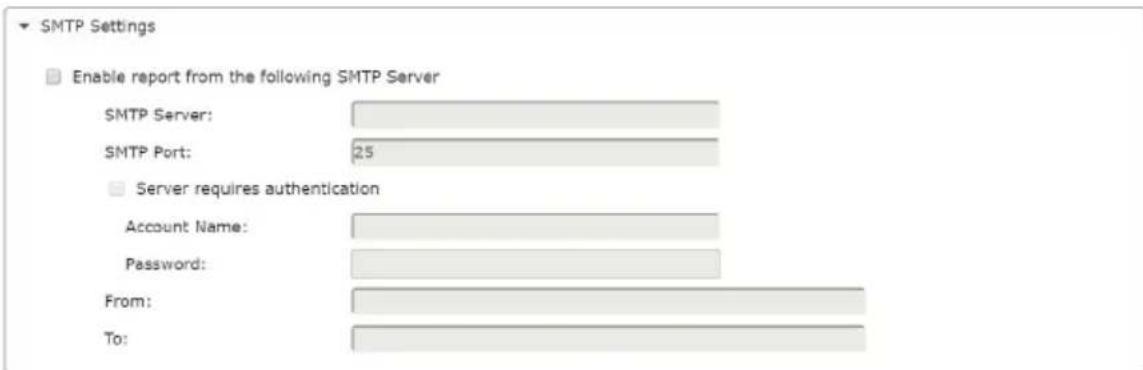
To have the Serial Console Server email reports from the SMTP server to you, do the following:
- Enable the Enable report from the following SMTP server, and key in either the IPv4 address, IPv6 address, or domain name of the SMTP server.
- Key in the SMTP port.
-
If your server requires authentication, put a check in the Server requires authentication checkbox, and key in the appropriate account information in the Account Name and Password fields.
-
Key in the email address of where the report is being sent from in the From field.
Note: 1. Only one email address is allowed in the From field, and it cannot exceed 64 Bytes.
2. 1 Byte = 1 English alphanumeric character.
- Key in the email address (addresses) of where you want the SMTP reports sent to in the To field.
Note: If you are sending the report to more than one email address, separate the addresses with a semicolon. The total cannot exceed 256 Bytes.
Log Server
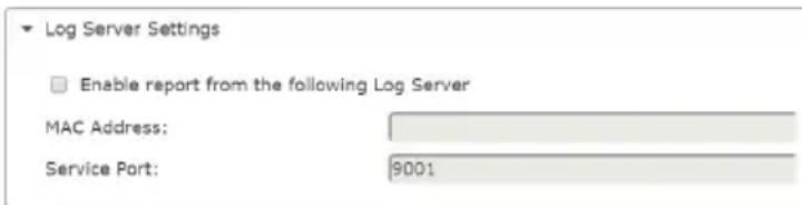
Important transactions that occur on the Serial Console Server, such as logins and internal status messages, are kept in an automatically generated log file.
- To enable this, put a check in the Enable report from the following Log Server checkbox.
- Specify the MAC address of the computer that the Log Server runs on in the MAC address field.
- Specify the port used by the computer that the Log Server runs on to listen for log details in the Service Port field. The valid port range is 1–65535. The default port number is 9001.
Note: The port number must different than the one used for the Program port.
SNMP Server
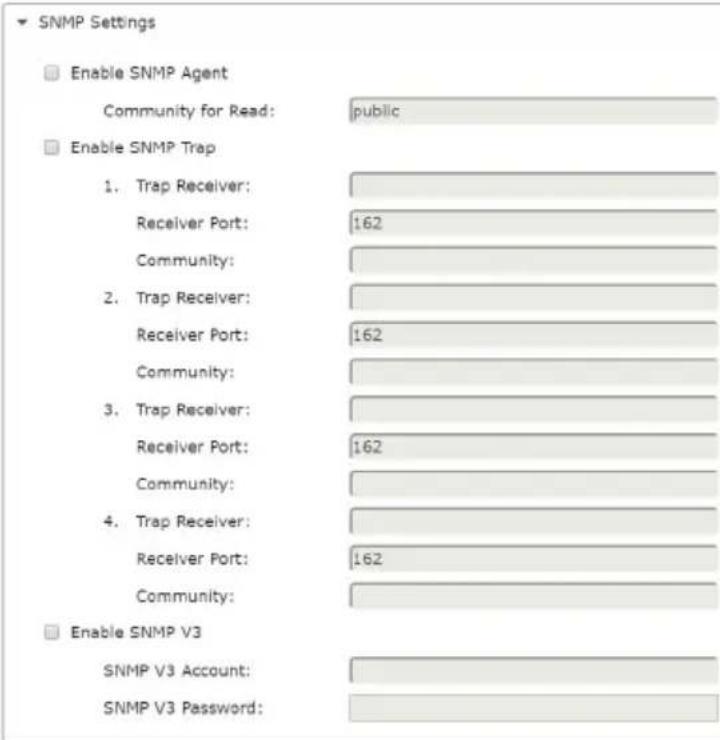
Up to four SNMP management stations can be specified. If you want to use SNMP trap notifications, do the following:
- Check Enable SNMP Trap and key in the Community.
- Key in the IP address(es) and the service port number(s) of the computer(s) to be notified of SNMP trap events. The valid port range is 1–65535. The default port number is 162.
Note: Make sure that the port number you specify here matches the port number used by the SNMP receiver computer.
- Key in the community value(s) if required for the SNMP version.
◆ To use SNMP V3, do the following:
- Check Enable SNMP V3.
- Key in the Community values.
- The client setting for the authorization protocol should only use SHA and AES-128 encryption.
♦ Syslog Server
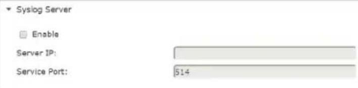
To record all the events that take place on Serial Console Server and write them to a Syslog server, do the following:
- Check Enable.
- Key in either the IPv4 address, IPv6 address, or domain name of the Syslog server.
- Key in the port number. The valid port range is 1-65535.
SMS Settings
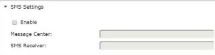
To receive notifications via SMS, do the following:
- Check Enable.
- Enter the telephone numbers for the Message Center and SMS Receiver.
Note: When you have made all your changes, remember to click Save at the bottom right corner of the page.
◆ External USB Drive
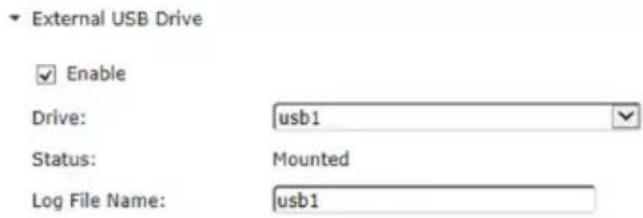
To record all the events that take place on Serial Console Server and write them to an external USB drive, do the following:
- Check Enable.
- Select the drive you wish to write the events to.
- Key in the file name for the log.
Authentication and Authorization
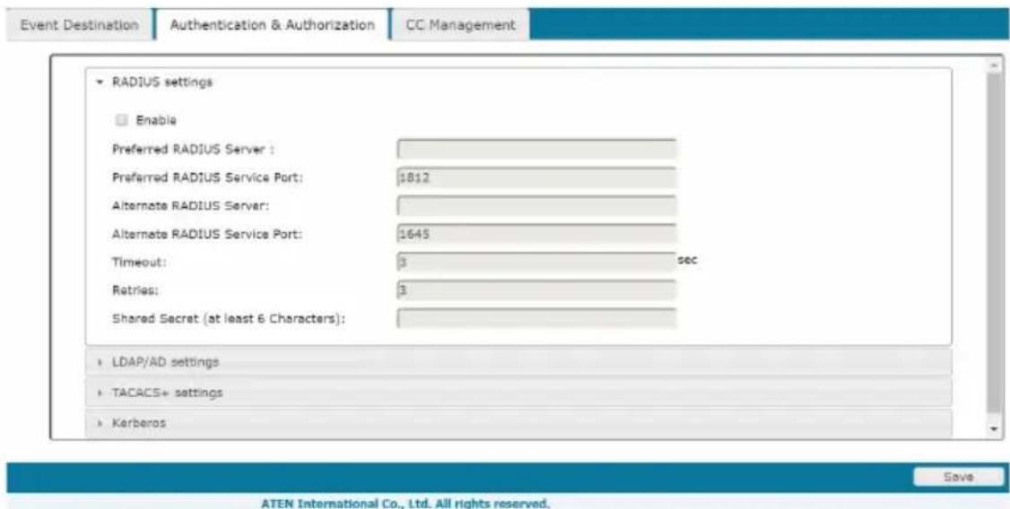
♦ RADIUS Settings
To allow authentication and authorization for the Serial Console Server through a RADIUS server, do the following:
- Check Enable.
- Fill in the IP addresses and service port numbers for the Preferred and Alternate RADIUS servers. You can use the IPv4 address, the IPv6 address or the domain name in the IP fields.
- In the Timeout field, set the time in seconds that the Serial Console Server waits for a RADIUS server reply before it times out.
- In the Retries field, set the number of allowed RADIUS retries.
-
In the Shared Secret field, key in the character string that you want to use for authentication between the Serial Console Server and the RADIUS Server. A minimum of 6 characters is required.
-
On the RADIUS server, Users can be authenticated with any of the following methods:
-
Set the entry for the user as su/xxxx
Where xxxx represents the Username given to the user when the account was created on the Serial Console Server. - Use the same Username on both the RADIUS server and the Serial Console Server.
- Use the same Group name on both the RADIUS server and the Serial Console Server.
- Use the same Username/Group name on both the RADIUS server and the Serial Console Server.
In each case, the user's access rights are the ones assigned that were assigned when the User of Group was created on the Serial Console Server. (See Adding Users, page 82.)
◆ LDAP / AD Settings
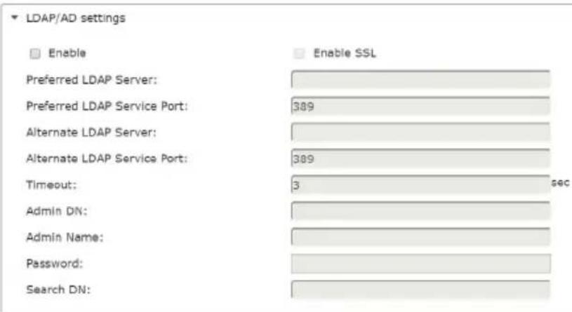
To allow authentication and authorization for the Serial Console Server via LDAP / AD, refer to the information in the table, below:
| Item Action | |
| Enable | Check the Enable checkbox to enable LDAP, and Enable SSL checkbox to enable LDAPS authentication and authorization. |
| LDAP Server IP and LDAP Service Port | Fill in the IP address and port number for the LDAP or LDAPS server.◆ You can use the IPv4 address, the IPv6 address or the domain name in the LDAP Server field.◆ For LDAP, the default port number is 389; for LDAPS, the default port number is 636. |
| Alternate LDAP Server and Alternate LDAP Service Port | Fill in the IP address and port number for the alternate LDAP or LDAPS server.◆ You can use the IPv4 address, the IPv6 address or the domain name in the Alternate LDAP Server field.◆ For an Alternate LDAP Service Port, the default port number is 389; for an Alternate LDAPS Service Port, the default port number is 636. |
| Admin DN Consult | the LDAP / LDAPS administrator to ascertain the appropriate entry for this field. For example, the entry might look like this:ou=kn4132,dc=aten,dc=com |
| Admin Name Key in the LDAP administrator's username. | |
| Admin Password Key in the LDAP administrator's password. | |
| Search DN Set the | distinguished name of the search base. This is the domain name where the search starts for user names. |
| Item Action | |
| Timeout | Set the time in seconds that the Serial Console Server waits for an LDAP or LDAPS server reply before it times out. |
On the LDAP / AD server, Users can be authenticated with any of the following methods:
- With MS Active Directory schema.
Note: If this method is used, the LDAP schema for MS Active Directory must be extended. Without schema – Only the Usernames used on the Serial Console Server are matched to the names on the LDAP / LDAPS server. User privileges are the same as the ones configured on the Serial Console Server.
- Without schema – Only Groups in AD are matched. User privileges are the ones configured for the groups he belongs to on the Serial Console Server.
- Without schema – Usernames and Groups in AD are matched. User privileges are the ones configured for the User and the Groups he belongs to on the Serial Console Server.
♦ TACACS+ Settings
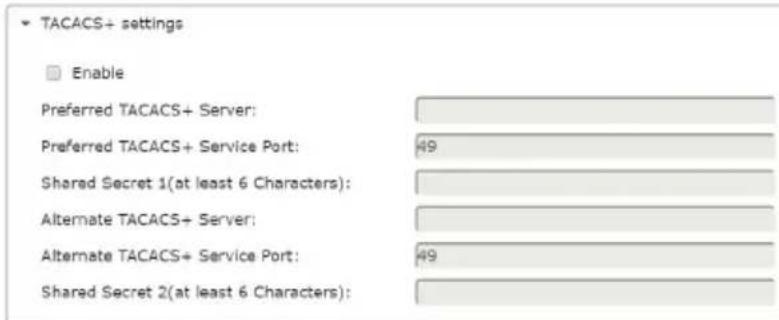
- Enable TACACS+ and enter the following information:
- Preferred TACACS+ Server
◆ Preferred TACACS+ Service Port - Shared Secret 1
Alternate TACACS+ Server
Alternate TACACS+ Service Port
Shared Secret 2
- Kerberos
- Kerberos
Enable
Kerberos Server:
Kerberos Service Port:
Kerberos Realm:

- Enable Kerberos and enter the following information:
- Kerberos Server
♦ Kerberos Service Port - Kerberos Realm
CC Management Settings
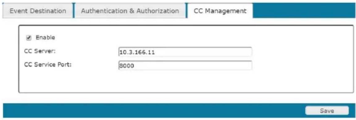
To allow authorization for the Serial Console Server through a CC (Control Center) server, check Enable and fill in the CC Server's IP address and Service port in the appropriate fields. You can use the IPv4 address, the IPv6 address or the domain name in the CC Server IP field.
Note: If this function is enabled, PON devices do not appear in the Sidebar, even if they are configured on the Serial Console Server. This is because they are managed via the CC server.
OOBC
In case the Serial Console Server cannot be accessed with the usual LAN-based methods, it can be accessed via the Serial Console Server's modem port or one of the serial ports (SN9108CO / SN9116CO) configured for a modem.
![Port Access User Management Device Management Log Maintenance ATEN Welcome to the SN013200 SN013200 [01]COM1 [02]COM2 [03]COM3 [04]COM4 [05]COM5 [06]COM6 [07]COM7 [08]COM8 [09]COM9 [10]COM10 [11]COM11 [12]COM12 [13]COM13 [14]COM14 Console Port Settings Baud Rate: 9600 Parity: None Data Bits: 9 bits Stop Bits: 1 bit Flow Control: None PPP Settings Modems Settings Initialization String: PPP Dial In Settings: Enable Dial In / Dial Back Enable Dial Back Show ATEN International Co., Ltd. All rights reserved.](/content/2026/06/1204310/images/56f8cbb6954018c464738e1298a067bfef842632e6de9dc3387082364bdbe4d2.jpg)
SN0108CO / SN0116CO / SN0132CO / SN0148CO
Console Port Settings
Baud Rate:
9600
Parity:
None
Data Bits:
8 bits
Stop Bits:
1 bit
Flow Control:
None
PPP Settings
Modem Settings
Initialization String:

PPP Dial In Settings
Enable Dial In / Dial Back
Enable Dial Back
Fixed Dial Back Number

Flexible Dial Back (Allow the caller to set the callback number)
PPP Server:
PPP Client:

PPP Dial Out Settings
Enable Dial Out
ISP Settings
Access Phone Number:
Username:
Password:

Dial Out Schedule
Every
2 Hours
Daily at
(HH:MM)
PPP online time:
30 minute(s)
Emergency dial out
PPP keeps online until network recovered
PPP online time
30 minute(s)
Mail Configuration
SMTP Server:
SMTP Port:
Server requires authentication
Account Name:
Password:
From:
To:
SN9108CO / SN9116CO
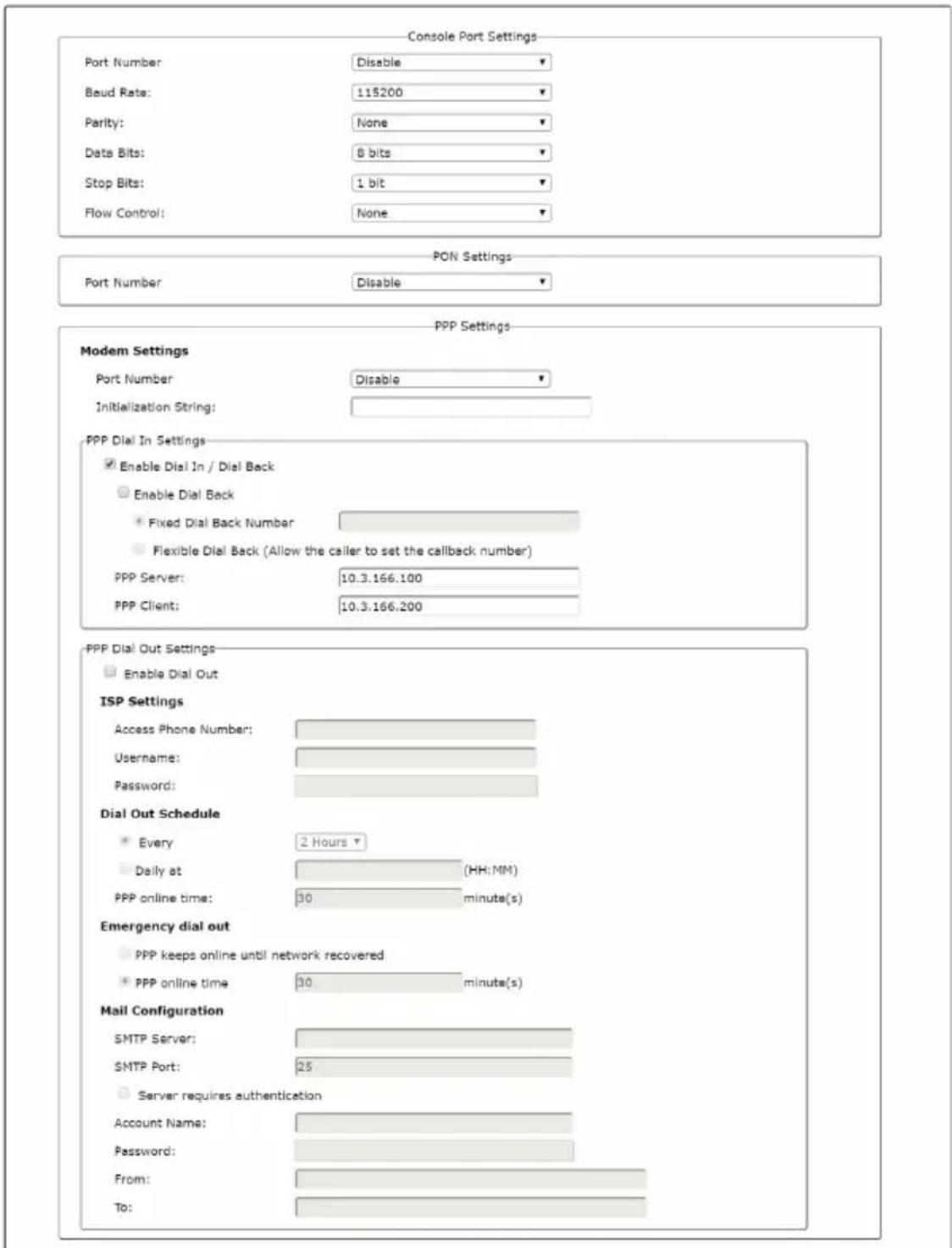
Select the Port Number that the Console, PON (reserved) and Modem is connected to on the rear of the SN9108CO / SN9116CO.
Enable Dial Back
When you enable Out of Band Access, the Enable Dial Back, and Enable Dial Out functions become available, as described in the sections that follow. As an added security feature, if this function is enabled, the Serial Console Server disconnects the calls that dial in to it, and dials back to one of the entries specified in the table below:
| Item Action | |
| Enable Fixed Number Dial Back | If Fixed Number Dial Back is enabled, when there is an incoming call, the Serial Console Server hangs up the modem and dials back to the modem whose phone number is specified in the Phone Number field.Key the phone number of the modem that you want the Serial Console Server to dial back to in the Phone Number field. |
| Enable Flexible Dial Back | If Flexible Dial Back is enabled, the modem that the Serial Console Server dials back to doesn't have to be fixed. It can dial back to any modem that is convenient for the user, as follows:1. Key the password that the users must specify in the Password field.2. When connecting to the Serial Console Server's modem, users specify the phone number of the modem that they want the Serial Console Server to dial back to as their Username, and specify the password set in the Password field for their password. |
Enable Dial Out
For the dial out function, you must establish an account with an Internet Service Provider, and use a modem to dial up to your ISP account. An explanation of the Enable Dial Out items is given in the table below:
| Item Action | |
| ISP Settings Specify the telephone number, account name (username), and password that you use to connect to your ISP. | |
| Item Action | |
| Dial Out Schedule | This entry sets up the times you want the Serial Console Server to dial out over the ISP connection.♦ Every provides a listing of fixed times from every hour to every four hours.♦ If you select Every two hours (for example), the Serial Console Server will start dialing out every two hours beginning at 00:00.♦ If you don't want the Serial Console Server to dial out on a fixed schedule, select Never from the list.♦ Daily at will dial out once a day at a specified time. Use the hh:mm format to specify the time.♦ PPP online time specifies how long you want the ISP connection to last before terminating the session and hanging up the modem. A setting of zero means it is always on line. |
| Emergency Dial Out | If the Serial Console Server gets disconnected from the network, or the network goes down, this function puts the Serial Console Server on line via the ISP dial up connection.♦ If you choose PPP stays online until network recovery, the PPP connection to the ISP will last until the network comes back up or the Serial Console Server reconnects to it.♦ If you choose PPP online time, the connection to the ISP will terminate after the amount of time that you specify is up. A setting of zero means it is always on line. |
| Dial Out Mail Configuration | This section provides email notification of problems that occur on the devices connected to the Serial Console Server's ports (see SMTP Settings, page 105).Note: This email notification differs from the one configured under SMTP Settings, page 105, in that it uses the ISP mail server rather than the internal company's mail server.♦ Key in the IPv4 address, IPv6 address, or domain name of your SMTP server in the SMTP Server IP Address field.♦ Key in the email address of the person responsible for the SMTP server (or some other equally responsible administrator), in the Email From field.♦ Key in the email address (addresses) of where you want the report sent to in the To field. If you are sending the report to more than one email address, separate the addresses with a comma or a semicolon.♦ If your server requires a secure SSL connection, put a check in the SMTP server requires secure connection (SSL) checkbox♦ If your server requires authentication, put a check in the SMTP server requires authentication checkbox, then key in the appropriate account name and password in the fields, below. |
When you have finished making your settings on this page, click Save.
Security
The Security page is divided into 4 main panels, as described in the sections that follow.
Login Failures
For increased security, the Login Failures section allows administrators to set policies governing what happens when a user fails to log in successfully.
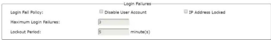
To set Login Failures, check one of the Login Fail Policy checkboxes. The meanings of the entries are explained in the table below:
| Entry Explanation | |
| Login Fail Policy This determines | what happens when a user fails to log in according to the security parameters that are set here. When a user exceeds the maximum login failures, you can set the Serial Console Server to:◆ Disable User Account◆ IP Address LockedThe amount of time the policy takes effect is set in the Lockout Period. |
| Maximum login Failures This field | sets the number of failed attempts a user is allowed before the Login Fail Policy is activated. |
| Lockout Period Sets the amount of time the User Account is disabled or IP Address is Locked before access will be reactivated. | |
Note: If a Login Fail Policy is not enabled, users can attempt to log in an unlimited number of times with no restrictions. For security purposes, we recommend that you enable this function and enable the lockout policies.
Security Level
For increased security, you can check or uncheck the boxes to High, Medium - high, Medium or Custom security features.
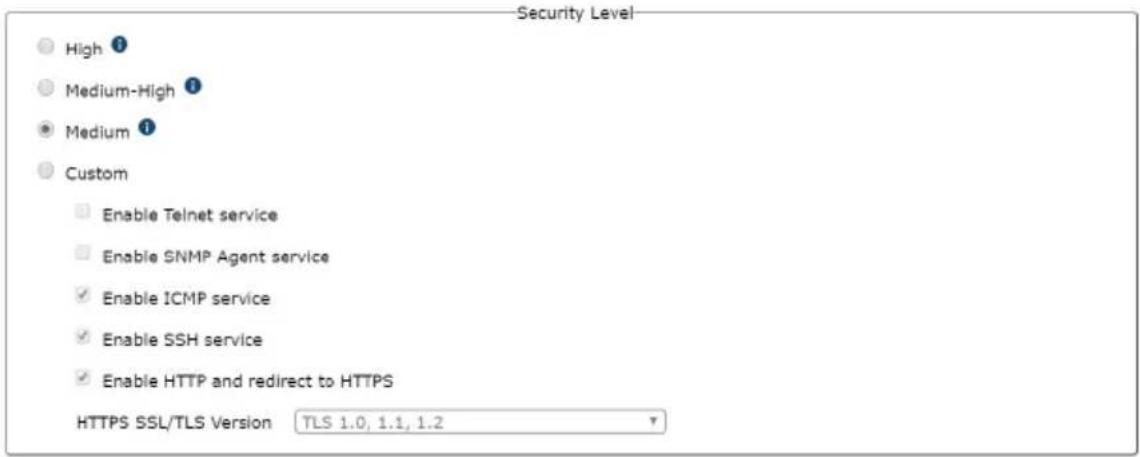
- High (Disable all services except: SSHv2, HTTPS(TLS v1.2))
- Medium-high (Enables SSHv2, redirect HTTP to HTTPS, HTTPS(TLS v1.2), ICMP)
- Medium (Enables SSHv2, redirect HTTP to HTTPS, HTTPS(TLS v1.0, 1.1, 1.2), SNMP Agent, ICMP) (Default)
- Custom: Click to check the following security options you wish to apply:
- Enable Telnet service
◆ Enable SNMP Agent service
- Enable ICMP service
◆ Enable SSH service (checked by default)
◆ Enable HTTP and redirect to HTTPS (checked by default)
- HTTPS SSL/TLS version: Select between “TLS 1.2”, ”TLS 1.0, 1.1, 1.2” (default), and “SSL 3.0, TLS 1.0, 1.1, 1.2”.
Working Mode
For increased security, you can check or uncheck the boxes to enable FIPS 140-2 for cryptographic modules.

IP/MAC Filter
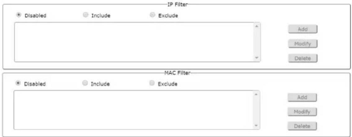
IP and MAC Filtering
IP and MAC Filters control access to the Serial Console Server based on the IP and/or MAC addresses of the client computers attempting to connect. A maximum of 100 IP filters and 100 MAC filters are allowed. If any filters have been configured, they appear in the IP Filter and/or MAC Filter list boxes.
To enable IP and/or MAC filtering, select one of the following radio buttons:
- If the Include button is selected, all the addresses within the filter are allowed access; all other addresses are denied access.
- If the Exclude button is selected, all the addresses within the filter are denied access; all other addresses are allowed access.
- Adding Filters
To add an IP filter, do the following:
- Click Add. A dialog box appears:
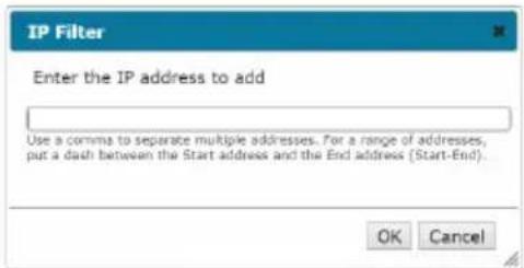
- Key the IP address you want to filter.
- After filling in the address, click OK.
- Repeat these steps for any additional IP addresses you want to filter.
To add a MAC filter, do the following:
- Click Add. A dialog box appears
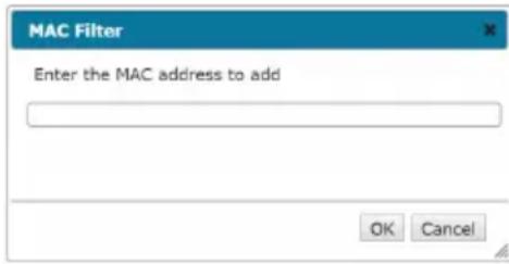
- Specify the MAC address in the dialog box, then click OK.
- Repeat these steps for any additional MAC addresses you want to filter.
◆ IP Filter / MAC Filter Conflict
If there is a conflict between an IP filter and a MAC filter – in other words, if a computer's address is allowed by one filter but blocked by the other – then the blocking filter takes precedence (the computer's access is blocked).
♦ Modifying Filters
To modify a filter, select it in the IP Filter or MAC Filter list boxes and click Modify. The Modify dialog box is similar to the Add dialog box. When it comes up, simply delete the old address(es) and replace it with the new one(s).
- Deleting Filters
To delete a filter, select it in the IP Filter or MAC Filter list box and click Delete.
Account Policy
In the Account Policy section, system administrators can set policies governing usernames and passwords.
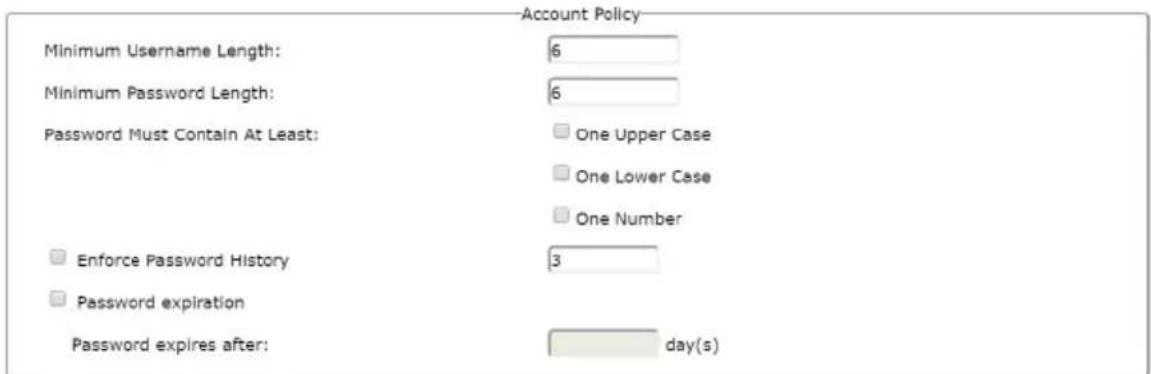
The meanings of the Account Policy entries are explained in the table below:
| Entry Explanation | |
| Minimum Username Length Sets | the minimum number of characters required for a username. Acceptable values are from 1–16. The default is 6. |
| Minimum Password Length Sets | the minimum number of characters required for a password. Acceptable values are from 0–16. A setting of 0 means that no password is required. Users can log in with only a Username. The default is 6. |
| Password Must Contain At Least | Checking any of these items requires users to include at least one uppercase letter, one lowercase letter or one number in their password.Note: This policy only affects user accounts created after this policy has been enabled, and password changes to existing user accounts. Users accounts created before this policy was enabled, and there is no change to the existing passwords, are not affected. |
| Enforce Password History Checking this box will require users to create a unique password that does not match the last x passwords they've used prior. X equals the number entered in the dialog box. | |
| Password Expiration Enter a value (in days) for all passwords to expire. | |
Association
The Association tab is currently reserved.
![Port Access User Management Device Management Log Maintenance ATEN Device | Network | ANMS | DOSC | Security | Association | Date/Time Welcome to the SN013200 SN013200 [01]COM1 [02]COM2 [03]COM3 [04]COM4 [05]COM5 [06]COM6 [07]COM7 [08]COM8 [09]COM9 [10]COM10 [11]COM11 [12]COM12 [13]COM13 [14]COM14 Power Management Summary POR Associate Settings Synchronization of On/OFF/Reboot: Power Supply Operation + Add Outlet Settings Confirmation Required: Power On Delay: sac Power Off Delay: soc Shutdown Method: MAC Address: POR Schedule Settings- Show](/content/2026/06/1204310/images/ca798b72434d344fa076924d1b2507bdb93975b150c69984c6655f1fec6568a8.jpg)
ATEN International Co., Ltd. All rights reserved.
Date/Time
The Date/Time dialog page sets the Serial Console Server time parameters:
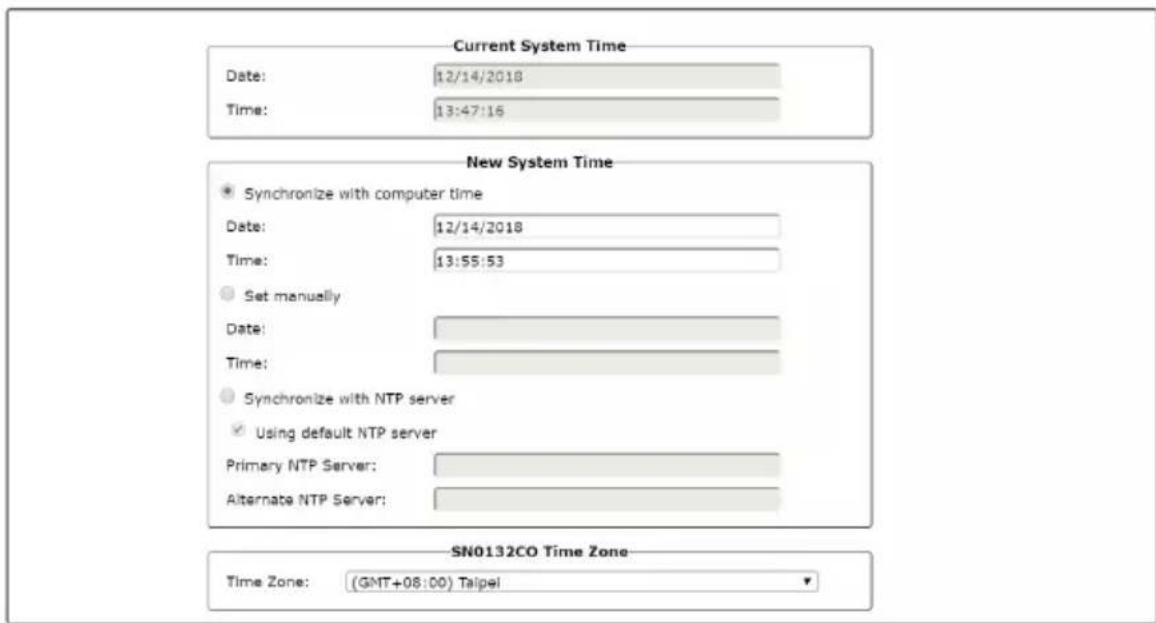
Set the parameters according to the information below.
Current System Time
This section displays the time and date that the switch is currently set to. The time and date fields are for information purposes and cannot be edited.
Note: In the Browser UI, the system time displays the time relative to the time zone that the web browser session originates from – not the time zone of the Switch. If the web browser session originates from a time zone that is different from the switch’s time zone, the time shown in the display will be different from the switch’s time.
New System Time
Use these fields to change the switch's time and date settings, as follows:
- To set the switch’s time and date to match the time and date of the computer you are logged in to, select the Synchronize with computer time radio button.
Note: Your computer's time and date are displayed in the fields just below the heading. These fields are for information purposes only.
- To set the time and date to values of your choosing, select the Set manually radio button and key the settings into their appropriate fields using the YYYY-MM-DD and HH:MM:SS formats.
Note: Date/time formats may differ depending on the selected interface language.
- To have the time automatically synchronized to a network time server, select the Synchronize with NTP server radio button:
- If you want to use your network’s default time server, put a check in the Using default NTP server checkbox.
- If you want to specify a time server, make sure that the Using default NTP server checkbox is unchecked, then key in the IP address of the time server of your choice in the Primary NTP Server field. If you want to configure an alternate time server, key in the IP address of the time server in the Alternate NTP Server field.
- Click Save to apply the changes.
Time Zone
- To establish the time zone that the Serial Console Server is located in, drop down the Time Zone list and choose the city that most closely corresponds to where it is located.
- Click Save to apply the changes.
Chapter 9 Log
Overview
The Serial Console Server logs all the events that take place on it. To view the contents of the log, click the Log tab. The device's System Log page appears:
![Log | Notification Setting SN0132CO [01]COM1 [02]COM2 [03]COM3 [04]COM4 [05]COM5 [06]COM6 [07]COM7 [08]COM8 [09]COM9 [10]COM10 [11]COM11 [12]COM12 [13]COM13 [14]COM14 System Log Time User Severity Log Information 2010-12-14 14:01:53 administrator Least Session stopped (Username: administrator, IP: 10.3.166.61, HTTPS Session: *****2dbc). 2010-12-14 13:44:58 administrator Least User (Username: administrator, IP: 10.3.41.138, HTTPS Session: *****55df) logged in successfully. 2010-12-14 13:44:58 administrator Least Session started (Username: administrator, IP: 10.3.41.138, HTTPS Session: *****55df). 2010-12-14 11:32:48 administrator Least User (Username: administrator, IP: 10.3.166.61, Session: *****2dbc) modified device setting. 2010-12-14 11:32:35 System Less Port (Port: 1) was offline. 2010-12-14 11:32:34 System Least Port (Port: 1) was online. 2010-12-14 11:32:33 System Less Port (Port: 1) was offline. 2010-12-14 11:32:27 System Least Port (Port: 1) was online. 2010-12-14 11:32:26 administrator Least Session stopped (Username: administrator, IP: 10.3.166.61, TELNET Session: *****563d). 2010-12-14 11:32:26 administrator Least User (Username: administrator, IP: 10.3.166.61, Session: *****563d) logged out. 2010-12-14 11:32:26 administrator Least Serial connection stopped (Username: administrator, Session: *****563d, Work mode: Console Management, Port: 1). 2010-12-14 11:32:26 System Less Port (Port: 1) was offline. 2010-12-14 11:31:59 administrator Least User (Username: administrator, IP: 10.3.166.61, Session: *****2dbc) modified device setting. 2010-12-14 11:31:51 administrator Least User (Username: administrator, IP: 10.3.166.61, Session: *****2dbc) modified device setting. Clear All Export Filter ATEN International Co., Ltd. All rights reserved.](/content/2026/06/1204310/images/cd3cc6b0e76bf8de22b8fc0c9b3b9e6fae11a2dfe08c0f7ee08aa21997684953.jpg)
System Log
The System Log page displays events that take place on the Serial Console Server, and provides a breakdown of the time, the severity, the user, and a description of each one. You can change the sort order of the display by clicking on the column headings.
The log file tracks a maximum of 512 events. When the limit is reached, the oldest events get discarded as new events come in. The purpose of the buttons at the bottom of the page are described in the table:
| Button Explanation | |
| Clear Log Clicking Clear Log | clears the log file. |
| Export Log | Clicking Export Log lets you save the contents of the log to a file on your computer. |
| Filter | Clicking Filter allows you to search for particular events by date or by specific words or strings, as described in the next section. |
Filter
Filter lets you narrow the log event display to ones that occurred at specific times; ones containing specific words or strings; or ones involving specific users. When you access this function, the log filter dialog box appears at the bottom of the page:
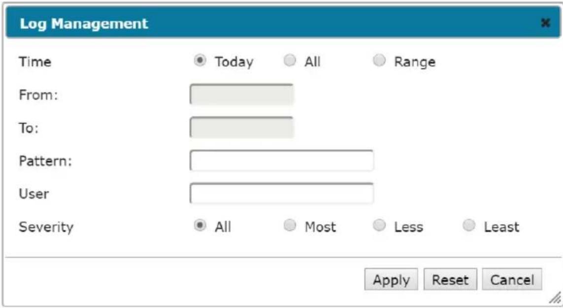
A description of the filter items is given in the table, below:
| Item Description | |
| Time This feature lets you filter for events that occurred at specific times, as follows:Today: Only the events for the current day are displayed.All: Select this radio button to filter results for all the records in the log file.Range: Select this radio button to filter results for records for a particular time period, then click theFromandTofields and a calendar will appear for you to select the dates. | |
| Pattern Filters for a particular word or string. Key the word or string into theInformationtext box. Only events containing that word or string are displayed. Wildcards (? for single characters; * for multiple characters) and the keywordorare supported. E.g., h*ds would return hands and hoods; h?nd would return hand and hind, but not hard; h*ds or h*ks would return hands and hooks. | |
| User Filters for specific users. Key in the user's Username; then clickApply. Only events containing that Username are displayed.Note: If theUserdoes not exist or the spelling is incorrect, no results will appear. | |
| Severity Filters based | on the severity rating of the event. Least severe events appear in black; Less severe events appear in blue; Most severe events appear in red.Check the radio button for the severity level that you want to display: All, Most, Less, or Least.Only events that match the severity level you specified appear in the display. |
| Apply Click to apply | the filter choices. |
| Reset Click this button | to clear the entries in the dialog box and start with a clean slate. |
| Cancel Click this button | to exit the log filter function without applying changes. |
Log Notification Settings
The Notification Settings page lets you decide which events trigger a notification:
Notification Setting
| Event | SNMP | Syslog | |
| ▸ Enable all system events | ✅ | ✅ | ✅ |
| ▸ Enable all authentication events | ✅ | ✅ | ✅ |
| ▸ Enable all user management events | ✅ | ✅ | ✅ |
| ▸ Enable all device management events | ✅ | ✅ | ✅ |
| ▸ Enable all system task events | ✅ | ✅ | ✅ |

The notifications are grouped into five groups: You can choose to enable the following:
All system events
◆ All authentication events
◆ All user management events
◆ All device management events
◆ All system task events
If you wish to turn on/off a particular notification, you may click on the icon to expand the groups to check/uncheck the individual notification:
Notification Setting
| Port online | ☑ | ☑ | ☑ |
| Port offline | ☑ | ☑ | ☑ |
| Alert String detected | ☑ | ☑ | ☑ |
| Got a DHCP address | ☑ | ☑ | ☑ |
| CC server connection success | ☑ | ☑ | ☑ |
| Enable all authentication events | ☑ | ☑ | ☑ |
| Login | ☑ | ☑ | ☑ |
| Login fail | ☑ | ☑ | ☑ |
| User locked | ☑ | ☑ | ☑ |
| IP address locked | ☑ | ☑ | ☑ |
| Logout | ☑ | ☑ | ☑ |
| Enable all user management events | ☑ | ☑ | ☑ |
| Enable all device management events | ☑ | ☑ | ☑ |
| Enable all system task events | ☑ | ☑ | ☑ |

Overview
The Maintenance function is used to upgrade firmware; backup and restore configuration and account information; and restore default values.
![Port Access User Management Device Management Log Maintenance Backup/Restore | Firmware Upgrade | Certificates SN0132CD [01]COM1 [02]COM2 [03]COM3 [04]COM4 [05]COM5 [06]COM6 [07]COM7 [08]COM8 [09]COM9 [10]COM10 [11]COM11 [12]COM12 [13]COM13 [14]COM14 Show ATEN International Co., Ltd. All rights reserved. Backup/Restore Password: Backup Backup Restore Filename: Choose File No file chosen Password: Options: Select All User Account User Define Device Configuration Network ANMS ODBC Security Port Configuration Backup/Restore](/content/2026/06/1204310/images/0f705c6f186919c8a313f9a38c2aa6ac8e0be0bd327b7e203def034b7d8f771b.jpg)
Backup / Restore
When you click on the Maintenance tab, it opens with the Backup/Restore page. This page gives you the ability to back up the Serial Console Server's configuration and user profile information:
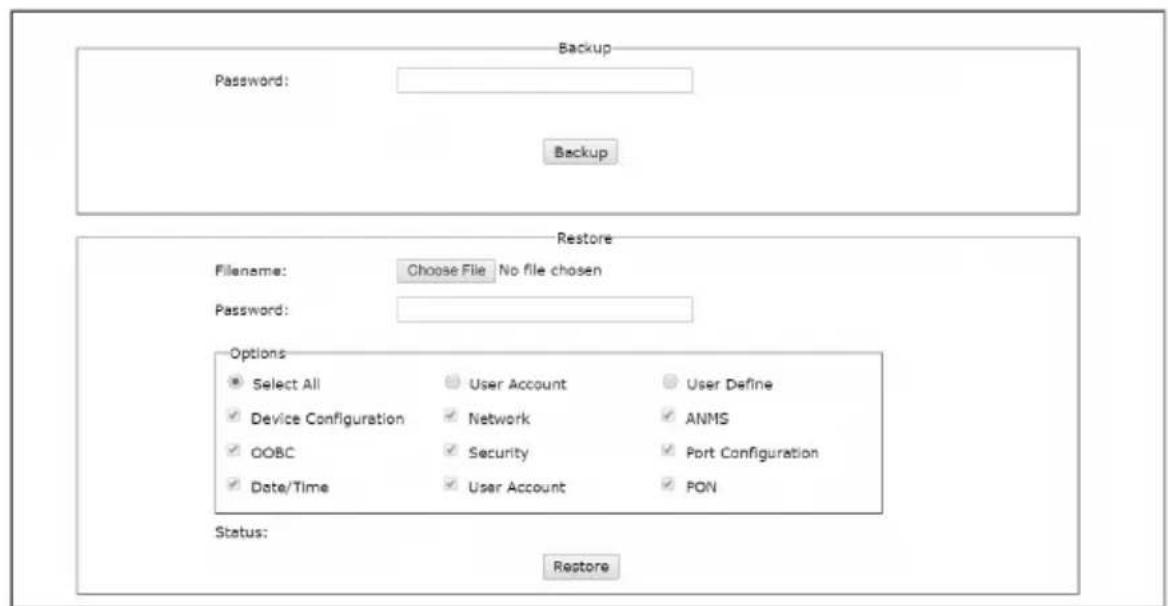
Backup
To backup the device's settings do the following:
- In the Password field, key in a password for the file.
Note: 1. Setting a password is optional. If you do not set one, the file can be restored without specifying a password.
2. If you do set a password, make a note of it, since you will need it to be able to restore the file.
- Click Backup.
- When the browser asks what you want to do with the file, select Save to disk; then save it in a convenient location.
Restore
To restore a previous backup, do the following:
- Click Browse; navigate to the file and select it.
Note: If you renamed the file, you can leave the new name. There is no need to return it to its original name.
- If you set a password when you created the file, key it in the Password field.
- Select as many of the options that are presented as you wish to restore.
- Click Restore.
After the file is restored, a message appears to inform you that the procedure succeeded.
Firmware Upgrade
This page can be used to upgrade the Serial Console Server's firmware. As new versions of the firmware become available, they can be downloaded from our website. Check the website regularly to find the latest information and packages.
To upgrade the main firmware, do the following:
- Download the new firmware file to your computer.
- Log in to the Serial Console Server and click the Maintenance tab. Then, open the Firmware Upgrade page:
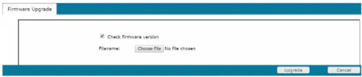
- Click Browse; navigate to the directory that the new firmware file is in and select the file.
-
Click Upgrade Firmware to start the upgrade procedure.
-
If you enabled Check Firmware Version the current firmware level is compared with that of the upgrade file. If the current version is equal to or higher than the upgrade version, a popup message appears, to inform you of the situation and stops the upgrade procedure.
- If you didn't enable Check Firmware Version, the upgrade file is installed without checking what its level is.
- As the upgrade proceeds, progress information is shown in the Progress bar.
-
Once the upgrade completes successfully, the Serial Console Server resets itself.
-
Log in again, and check the firmware version to be sure it is the new one.
Certificates
This page provides information on the Private Certificates:
![Port Access User Management Device Management Log Maintenance Backup/Restore | Firmware Upgrade | Certificates Welcome to the SN0132CD SN0132CD [01]COM1 [02]COM2 [03]COM3 [04]COM4 [05]COM5 [06]COM6 [07]COM7 [08]COM8 [09]COM9 [10]COM10 [11]COM11 [12]COM12 [13]COM13 [14]COM14 Private Certificate Name Description Issued To Common Name(CN) ATEN INTERNATIONAL CO.,LTD Organization(O) ATEN INTERNATIONAL CO.,LTD Organization Unit (OU) RSD Country(C) TW State or Province (ST).New Taipei City Locality (L) Sighih District Email Address (E): eserviciati@asp.com.tw. Show New Get CSR Import Restore Defaults ATEN International Co., Ltd. All rights reserved.](/content/2026/06/1204310/images/52424316f46460a2fcd3216b7d86bf6ee5fb72da28512e72bf9e446834ea54eb.jpg)
Private Certificate
When logging in over a secure (SSL) connection, a signed certificate is used to verify that the user is logging in to the intended site. For enhanced security, the Private Certificate section allows you to use your own private encryption key and signed certificate, rather than the default ATEN certificate.
There are two methods for establishing your private certificate: generating a self-signed certificate; and importing a third-party certificate authority (CA) signed certificate.
- Generating a Self-Signed Certificate
If you wish to create your own self-signed certificate, a free utility – openssl.exe – is available for download over the web.
- Obtaining a CA Signed SSL Server Certificate
For the greatest security, we recommend using a third party certificate authority (CA) signed certificate. To obtain a third party signed certificate, go to a CA (Certificate Authority) website to apply for an SSL certificate. After the CA sends you the certificate and private encryption key, save them to a convenient location on your computer.
- Importing the Private Certificate
To import the private certificate, do the following:
- Click Import from the bottom of the Private Certificate page, shown here:

- Click Browse to the right of Certificate Filename; and browse to where your certificate file is located; and select it.
- Click Import to complete the procedure.
Note: Clicking Restore Defaults returns the device to using the default ATEN certificate.
Certificate Signing Request
The Certificate Signing Request (CSR) section provides an automated way of obtaining and installing a CA signed SSL server certificate.

To perform this operation do the following:
- Click New. The following dialog box appears:
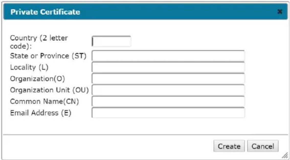
- Fill in the form – with entries that are valid for your site – according to the example information in the following table:
| Information Example | |
| Country (2 letter code) TW | |
| State or Province Taiwan | |
| Locality Taipei | |
| Organization Your Company. | Ltd. |
| Unit Tech Department | |
| Common Name mycompany.com | Note: This must be the exact domain name of the site that you want the certificate to be valid for. If the site's domain name is www.mycompany.com, and you only specify mycompany.com, the certificate will not be valid. |
| Email Address administrator@yourcompany.com | |
- After filling in the form (all fields are required), click Create.
A self-signed certificate based on the information you just provided is now stored on the CCVSR.
- Click Get CSR, and save the certificate file (csr.cer) to a convenient location on your computer.
This is the file that you give to the third party CA to apply for their signed SSL certificate.
-
After the CA sends you the certificate, save it to a convenient location on your computer.
-
Click Import from the lower menu bar and the Private Certificate window pops up, as shown here:
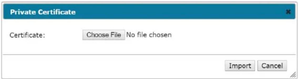
- Click Choose File to locate the certificate and select it as the Certificate Filename; then click Import to store it on the Serial Console Server.
Note: When you upload the file, the Serial Console Server checks the file to make sure the specified information still matches. If it does, the file is accepted; if not, it is rejected.
If you want to remove the certificate (to replace it with a new one because of a domain name change, for example), simply click Restore Defaults.
This Page Intentionally Left Blank
Safety Instructions
General
- This product is for indoor use only.
- Read all of these instructions. Save them for future reference.
◆ Follow all warnings and instructions marked on the device. - Do not place the device on any unstable surface (cart, stand, table, etc.). If the device falls, serious damage will result.
♦ Do not use the device near water. - Do not place the device near, or over, radiators or heat registers.
- The device cabinet is provided with slots and openings to allow for adequate ventilation. To ensure reliable operation, and to protect against overheating, these openings must never be blocked or covered.
- The device should never be placed on a soft surface (bed, sofa, rug, etc.) as this will block its ventilation openings. Likewise, the device should not be placed in a built-in enclosure unless adequate ventilation has been provided.
- Never spill liquid of any kind on the device.
- Unplug the device from the wall outlet before cleaning. Do not use liquid or aerosol cleaners. Use a damp cloth for cleaning.
- Avoid circuit overloads. Before connecting equipment to a circuit, know the power supply’s limit and never exceed it. Always review the electrical specifications of a circuit to ensure that you are not creating a dangerous condition or that one doesn’t already exist. Circuit overloads can cause a fire and destroy equipment.
- The device should be operated from the type of power source indicated on the marking label. If you are not sure of the type of power available, consult your dealer or local power company.
- To prevent damage to your installation it is important that all devices are properly grounded.
- The device is designed for IT power distribution systems with 230V phase-to-phase voltage.
- The device is equipped with a 3-wire grounding type plug. This is a safety feature. If you are unable to insert the plug into the outlet, contact your
electrician to replace your obsolete outlet. Do not attempt to defeat the purpose of the grounding-type plug. Always follow your local/national wiring codes.
- Do not allow anything to rest on the power cord or cables. Route the power cord and cables so that they cannot be stepped on or tripped over.
If an extension cord is used with this device make sure that the total of the ampere ratings of all products used on this cord does not exceed the extension cord ampere rating. Make sure that the total of all products plugged into the wall outlet does not exceed 15 amperes.
- To help protect your system from sudden, transient increases and decreases in electrical power, use a surge suppressor, line conditioner, or un-interruptible power supply (UPS).
- Position system cables and power cables carefully; Be sure that nothing rests on any cables.
- When connecting or disconnecting power to hot-pluggable power supplies, observe the following guidelines:
- Do not allow anything to rest on the power cord or cables. Route the power cord and cables so that they cannot be stepped on or tripped over. - If an extension cord is used with this device make sure that the total of the ampere ratings of all products used on this cord does not exceed the extension cord ampere rating. Make sure that the total of all products plugged into the wall outlet does not exceed 15 amperes. - To help protect your system from sudden, transient increases and decreases in electrical power, use a surge suppressor, line conditioner, or un-interruptible power supply (UPS). - Position system cables and power cables carefully; Be sure that nothing rests on any cables. - When connecting or disconnecting power to hot-pluggable power supplies, observe the following guidelines:
- Install the power supply before connecting the power cable to the power supply.
- Unplug the power cable before removing the power supply.
- If the system has multiple sources of power, disconnect power from the system by unplugging all power cables from the power supplies.
- Never push objects of any kind into or through cabinet slots. They may touch dangerous voltage points or short out parts resulting in a risk of fire or electrical shock.
- Do not attempt to service the device yourself. Refer all servicing to qualified service personnel.
- If the following conditions occur, unplug the device from the wall outlet and bring it to qualified service personnel for repair.
- The power cord or plug has become damaged or frayed.
- Liquid has been spilled into the device.
- The device has been exposed to rain or water.
- The device has been dropped, or the cabinet has been damaged.
- The device exhibits a distinct change in performance, indicating a need for service.
- The device does not operate normally when the operating instructions are followed.
- Only adjust those controls that are covered in the operating instructions. Improper adjustment of other controls may result in damage that will require extensive work by a qualified technician to repair.
DC Power
- The system relies on the protective devices in the building installation for protection against short-circuit, overcurrent, and earth (grounding) fault. Ensure that the protective devices in the building installation are properly rated to protect the system, and that they comply with national and local codes.
- Ensure that there is a readily accessible disconnect device incorporated in the building's installation wiring.
- A separate protective earthing terminal is provided on this product and shall be permanently connected to earth.
-
For the DC supply circuit, select a DC supply cable that is certified by UL, AWM VW-1 Style 1015, minimum 16 AWG, minimum 105^ , minimum 300V .
CAUTION: This equipment is designed to permit the connection of the earthed conductor of the DC supply circuit to the earthing conductor at the equipment. If this connection is made, all of the following conditions must be met: -
This equipment shall be connected directly to the DC supply system earthing electrode conductor or to a bonding jumper from an earthing terminal bar or bus to which the DC supply system earthing electrode conductor is connected.
- This equipment shall be located in the same immediate area (such as adjacent cabinets) as any other equipment that has a connection between the earthed conductor of the same DC supply circuit and the earthing conductor, and also the point of earthing of the DC system. The DC system shall not be earthed elsewhere.
- The DC supply source is to be located within the same premises as this equipment.
- Switching or disconnecting devices shall not be in the earthed circuit conductor between the DC source and the point of connection of the earthing electrode conductor.
- WARNING: This unit is intended for installation in restricted access areas. A restricted access area (server room, data center, etc.) is where access can only be gained by service personnel through the use of a special tool, lock and key, or other means of security, and is controlled by the authority responsible for the location.
Rack Mounting
- Before working on the rack, make sure that the stabilizers are secured to the rack, extended to the floor, and that the full weight of the rack rests on the floor. Install front and side stabilizers on a single rack or front stabilizers for joined multiple racks before working on the rack.
- Always load the rack from the bottom up, and load the heaviest item in the rack first.
- Make sure that the rack is level and stable before extending a device from the rack.
- Use caution when pressing the device rail release latches and sliding a device into or out of a rack; the slide rails can pinch your fingers.
- After a device is inserted into the rack, carefully extend the rail into a locking position, and then slide the device into the rack.
- Do not overload the AC supply branch circuit that provides power to the rack. The total rack load should not exceed 80 percent of the branch circuit rating.
- Make sure that all equipment used on the rack – including power strips and other electrical connectors – is properly grounded.
- Ensure that proper airflow is provided to devices in the rack.
- Ensure that the operating ambient temperature of the rack environment does not exceed the maximum ambient temperature specified for the equipment by the manufacturer
- Do not step on or stand on any device when servicing other devices in a rack.
Technical Support
International
- For online technical support – including troubleshooting, documentation, and software updates: http://support.aten.com
- For telephone support, see Telephone Support, page iv.
North America
| Email Support support@aten-usa.com | ||
| Online Technical Support | Troubleshooting Documentation Software Updates | http://www.aten-usa.com/support |
| Telephone Support 1-888-999-ATEN | ext 49881-949-428-1111 | |
When you contact us, please have the following information ready beforehand:
◆ Product model number, serial number, and date of purchase.
- Your computer configuration, including operating system, revision level, expansion cards, and software.
◆ Any error messages displayed at the time the error occurred.
◆ The sequence of operations that led up to the error.
◆ Any other information you feel may be of help.
Specifications
SN0108CO / SN0116CO
| Function SN0108CO SN0116CO | |||
| Serial Connections 8 16 | |||
| Connectors Serial 8 x | RJ45 Female 16 x RJ45 | Female | |
| LAN 2 x RJ45 | |||
| Power 2 x IEC 60320/C14 | |||
| PON 1 x RJ45 Female (Reserved) | |||
| Modem 1 x RJ45 Female | |||
| USB 3 x USB Type A Female | |||
| USB Console (LUC) 1 x | Mini USB | ||
| Local Console | 1 x RJ45 Female | ||
| Switches | Reset | 1 x Recessed Pushbutton | |
| Power | 2 x Rocker Switch | ||
| LEDs | Serial Port Status | 8 (Green) | 16 (Green) |
| 10 / 100 / 1000 Mbps | 2 (Red / Orange / Green) | ||
| Power | 2 (Blue) | ||
| I/P Rating | AC | 100-240V~; 50/60Hz; 1A | |
| Power Consumption | 110V/14.1W; 220V/14W | 110V/15.4W; 220V/14.9W | |
| Mode of Operation | Console Management, Console Management Direct, Real Com Port, TCP Server/Client, UDP Server/Client, Virtual Modem | ||
| Environment | Operating Temp. | 0-40°C | |
| Storage Temp. | -20-60°C | ||
| Humidity | 0-80% RH Noncondensing | ||
| Physical Properties | Housing | Metal | |
| Weight | 4.45 kg | 4.48 kg | |
| Dimensions L x W x H | 43.72 x 32.98 x 4.40 cm (19"1U) | 43.72 x 32.98 x 4.40 cm (19"1U) | |
SN0108COD / SN0116COD
| Function SN0108COD SN0116COD | |||
| Serial Connections 8 16 | |||
| Connectors Serial 8 x | RJ45 Female 16 x RJ45 Female | ||
| LAN 2 x RJ45 | |||
| Power 1 x 5-Pin Terminal Block (Green) | |||
| PON 1 x RJ45 Female (Reserved) | |||
| Modem 1 x RJ45 Female | |||
| USB 3 x USB Type A Female | |||
| USB Console (LUC) 1 x Mini USB | |||
| Local Console | 1 x RJ45 Female | ||
| Switches | Reset | 1 x Recessed Pushbutton | |
| Power | 2 x Rocker Switch | ||
| LEDs | Serial Port Status | 8 (Green) | 16 (Green) |
| 10 / 100 / 1000 Mbps | 2 (Red / Orange / Green) | ||
| Power | 2 (Blue) | ||
| I/P Rating | DC | 36-48 V DC; 1.6 A in 5-Pin Terminal Block | |
| Power Consumption | DC48V/15.79W | DC48V/16.22W | |
| Mode of Operation | Console Management, Console Management Direct, Real Com Port, TCP Server/Client, UDP Server/Client, Virtual Modem | ||
| Environment Operating | Temp. | 0-40°C | |
| Storage Temp. | -20-60°C | ||
| Humidity | 0-80% RH Noncondensing | ||
| Physical Properties | Housing | Metal | |
| Weight | 4.46 kg | 4.5 kg | |
| Dimensions L x W x H | 43.72 x 32.85 x 4.40 cm | ||
SN0132CO / SN0148CO
| Function SN0132CO SN0148CO | |||
| Serial Connections 32 48 | |||
| Connectors Serial 32 x RJ45 Female 48 x RJ45 | Female | ||
| Switches | Reset | 1 x Recessed Pushbutton | |
| Power | 2 x Rocker Switch | ||
| LEDs | Serial Port Status | 32 (Green) | 48 (Green) |
| 10 / 100 / 1000 Mbps | 2 (Red / Orange / Green) | ||
| Power | 2 (Blue) | ||
| I/P Rating | AC 100-240V~; 50 | -60Hz; 1.8A | |
| Power Consumption | 110V/20.2W; 220V/21W | 110V/25.8W; 220V/26.2W | |
| Mode of Operation | Console Management, Console Management Direct, Real Com Port, TCP Server/Client, UDP Server/Client, Virtual Modem | ||
| Environment | Operating Temp. | 0–40°C | |
| Storage Temp. | -20–60°C | ||
| Humidity | 0–80% RH Noncondensing | ||
| Physical Properties | Housing | Metal | |
| Weight | 4.84 kg | 4.92 kg | |
| Dimensions L x W x H | 43.84 x 32.77 x 4.40 cm | ||
SN0132COD / SN0148COD
| Function SN0132COD SN0148COD | |||
| Serial Connections 32 48 | |||
| Connectors Serial 32 x RJ45 Female | (Black) | 48 x RJ45 Female (Black) | |
| Switches | Reset | 1 x Recessed Pushbutton | |
| Power | 2 x Rocker Switch | ||
| LEDs | Serial Port Status | 32 (Green) | 48 (Green) |
| 10 / 100 / 1000 Mbps | 2 (Red / Orange / Green) | ||
| Power | 2 (Blue) | ||
| I/P Rating | DC | 36-48 V DC; 1.6 A in 5-Pin Terminal Block | |
| Power Consumption | DC48V/22.1W | DC48V/27.3W | |
| Mode of Operation | Console Management, Console Management Direct, Real Com Port, TCP Server/Client, UDP Server/Client, Virtual Modem | ||
| Environment Operating | Temp. | 0–40°C | |
| Storage Temp. | -20–60°C | ||
| Humidity | 0–80% RH Noncondensing | ||
| Physical Properties | Housing | Metal | |
| Weight | 4.99 kg | 5.06 kg | |
| Dimensions L x W x H | 43.84 x 32.77 x 4.40 cm | ||
SN9108CO / SN9116CO
| Function SN9108CO SN9116CO | |||
| Serial Connections 8 16 | |||
| Connectors Serial 8 x RJ45 Female 16 x RJ45 Female | |||
| LAN 1 x RJ45 | |||
| Power 1 x IEC60320/C14 | |||
| Switches Reset 1 x Recessed Pushbutton | |||
| Power 1 x Rocker Switch | |||
| LEDs Serial Port Status | 8 (Green) | 16 (Green) | |
| 10 / 100 / 1000 Mbps | 1 (Red / Orange / Green) | ||
| Power | 1 (Blue) | ||
| I/P Rating | AC | 100-240V~, 50/60 Hz, 1A | |
| Power Consumption | 110V/9.7W; 220V/9.6W | 110V/10.9W; 220V/11.6W | |
| Mode of Operation | Console Management, Console Management Direct, Real Com Port, TCP Server/Client, UDP Server/Client, Virtual Modem | ||
| Environment | Operating Temp. | 0–40°C | |
| Storage Temp. | -20–60°C | ||
| Humidity | 0–80% RH Noncondensing | ||
| Physical Properties | Housing | Metal | |
| Weight | 3.12 kg | 3.16 kg | |
| Dimensions L x W x H | 43.72 x 21.76 x 4.40 cm(19"1U) | 43.72 x 21.76 x 4.40 cm(19"1U) | |
IP Address Determination
If you are an administrator logging in for the first time, you need to access the Serial Console Server in order to give it an IP address that users can connect to. There are three methods to choose from. In each case, your client computer must be on the same network segment as the Serial Console Server. After you have connected and logged in you can give the Serial Console Server its fixed network address. (See Network, page 100.)
The Local Console
The easiest way to assign an IP address is from the local console. Refer to First Time Setup, page 33, for details on the procedure involved.
IP Installer
For client computers running Windows, an IP address can be assigned with the IP Installer utility. The utility can be obtained from the Download area of our website. Look under Driver/SW, and the model of your Serial Console Server. After downloading the utility to your client computer, do the following:
- Unzip the contents of IPInstaller.zip to a directory on your hard drive.
- Go to the directory that you unzipped the IPInstaller program to and run IPInstaller.exe. A dialog box similar to the one below appears:
![Network Device IP Installer Device list: Device Name Model Name MAC Address IP Address SN0132 00-10-74-61 Protocol: IPv4 Network adapter: MAC: 50e5.43ed-e0-6d, IP: 10.3.41.141 IPv4 settings Obtain an IPv4 address automatically [DHCP] Use the following IPv4 address: IP address 0 0 0 0 Subnet mask 0 0 0 0 Default gateway: 0 0 0 0 Obtain DNS server address automatically Use the following DNS server addresses: Preferred DNS server: . . . . Alternate DNS server: . . . . IPv6 settings Obtain an IPv6 address automatically [DHCP] Use the following IPv6 address: IPv6 address Subnet prefix length: Default gateway: Obtain DNS server address automatically Use the following DNS server addresses: Preferred DNS server: Alternate DNS server:](/content/2026/06/1204310/images/2d114541fc460180f35aa3807a0cae2005bf8f60b588992193f1d3534dd5bb46.jpg)
- Select the Serial Console Server in the Device List.
Note: 1. If the list is empty, or your device doesn't appear, click Enumerate to refresh the Device List.
2. If there is more than one device in the list, use the MAC address to pick the one you want. The Serial Console Server MAC address is located on its bottom panel.
4. Select either Obtain an IP address automatically (DHCP), or Specify an IP address. If you chose the latter, fill the IP Address, Subnet Mask, and Gateway fields with the information appropriate to your network.
5. Click Set IP.
6. After the IP address shows up in the Device List, click Exit. See IP Installer, page 101 for more information.
Browser
- Set your client computer's IP address to 192.168.0.XXX Where XXX represents any number or numbers except 60. (192.168.0.60 is the default address of the Serial Console Server.)
- Specify the Serial Console Server's default IP address (192.168.0.60) in your browser, and you will be able to connect.
- Assign a fixed IP address for the Serial Console Server that is suitable for the network segment that it resides on.
- After you log out, reset your client computer's IP address to its original value.
IPv6
At present, the Serial Console Server supports three IPv6 address protocols: Link Local IPv6 Address, IPv6 Stateless Autoconfiguration, and Stateful Autoconfiguration (DHCPv6).
Link Local IPv6 Address
At power on, the Serial Console Server is automatically configured with a Link Local IPv6 Address (for example, fe80:210:74ff:fe61:1ef). To find out what the Link Local IPv6 Address is, log in with the Serial Console Server IPv4 address and open the Device Management → Device Information page. The address is displayed in the General list box (see page 97).
Once you have determined what the IPv6 address is, you can use it when logging in from a browser or the Win and Java Client AP programs.
For example:
If you are logging in from a browser, you would key in
http://[fe80:2001:74ff:fe6e:59%5]
for the URL bar.
If you are logging in with the AP program, you would key:
fe80:2001:74ff:fe6e:59%5
for the IP field of the Server panel (see Remote Login, page 36).
Note: 1. To log in with the Link Local IPv6 Address, the client computer must be on the same local network segment as the Serial Console Server
2. The %5 is the %interface used by the client computer. To see your client computer's IPv6 address: from the command line issue the following command: ipconfig /all. The % value appears at the end of the IPv6 address.
IPv6 Stateless Autoconfiguration
If the Serial Console Server network environment contains a device (such as a router) that supports the IPv6 Stateless Autoconfiguration function, the Serial Console Server can obtain its prefix information from that device in order to generate its IPv6 address. For example, 2001:74ff:fe6e:59.
As above, the address is displayed in the General list box of the Device Management Device Information page (see page 97).
Once you have determined what the IPv6 address is, you can use it when logging in from a browser or the Win and Java Client AP programs.
For example:
If you are logging in from a browser, you would key in
http://[2001:74ff:fe6e:59]
for the URL bar.
If you are logging in with the AP program, you would key:
2001:74ff:fe6e:59
for the IP field of the Server panel.
Virtual Modem Details
The Serial Console Server's Virtual Modem function emulates a hardware modem to provide high speed serial modem functionality over an Ethernet LAN or WAN using TCP/IP rather than over slower, less-reliable, telephone lines.
AT Command Set Support
The Serial Console Server supports a subset of the standard Hayes command set, as well as some extended commands, as shown in the following table:
| Command | Operation Response | |
| +++ Return to command mode. The escape character can be changed by modifying the S2 register. | none | |
| A/ Repeat at the last command string If successful: OK[CR][LF] | If failure: ERROR[CR][LF] | |
| ATA[CR] Answer mode. Allow virtual modem to listen for a TCP connection on the provided listen port: 5301. | If successful: OK[CR][LF]If failure: ERROR[CR][LF] | |
| ATD(T) Remote IP:Remote Port[CR] | Try to establish a TCP connection and connect to the specified remote host.e.g. ATDT10.0.0.72:50001Note:The SN3101 accepts T and P additions to the ATD command, but ignores them. | If successful: CONNECT[CR][LF]If connection failure:NO CARRIER[CR][CF]If other error:ERROR[CR][LF] |
| ATEn[CR] Where n represents a numeric character (0 or 1.):E0: disable command echoE1: enable command echo | If successful: OK[CR][LF]If failure: ERROR[CR][LF] | |
| ATH[CR] Hang up current TCP connection if a connection is active.Note: ATH, ATH0, and ATH1 all act the same. | If successful: OK[CR][LF]If failure: ERROR[CR][LF] | |
| ATIn[CR] Inquiry command. (Where n represents a numeric character; 0 or 1.):E0: Display ATEN International Co. Ltd.E1: Display Serial Console Server | If successful: OK[CR][LF]If failure: ERROR[CR][LF] | |
| ATOn[CR] Return to on-line data mode. (Where n represents a numeric character; 0 or 1.)If the modem is in the on-line command mode, the modem enters on-line data mode. If the modem is in the off-line command mode (no TCP connection established), an ERROR is returned.O0, O1: If there is an active connection, switch the modem to data mode. | If an active TCP connection:OK[CR][LF]Otherwise:ERROR[CR][LF] | |
| ATQn[CR] Result code control command. (Where n represents a numeric character; 0 or 1.)Q0: Enable result code to DTE (default)Q1: Disable result code to DTE. | If successful: OK[CR][LF]If failure: ERROR[CR][LF] | |
| ATSn?[CR] Reports the value of the S register. (Where n is the register's number.) | If successful: OK[CR][LF]If failure: ERROR[CR][LF] | |
| ATSn=v[CR] Sets the S register's value. (Where n is the register's number; and v is the S register value.) | If successful: OK[CR][LF]If failure: ERROR[CR][LF] | |
| ATVn[CR] Result code return type. (Where n represents a numeric character; 0 or 1.)V0: Response is:[CR][LF]V1: Response is:[CR][LF] | If successful: OK[CR][LF]If failure: ERROR[CR][LF] | |
(Continued from previous page.)
| Command | Operation Response | |
| ATZ[CR] | Reset modem command.Close active connections and reset the S registers and general option status to their saved values. | If successful: OK[CR][LF]If failure: ERROR[CR][LF] |
| AT&Cn[CR] | DCD option. (Where n represents a numeric character; 0 or 1.)&C0: DCD is ON at all times.&C1: DCD matches the state of the TCP connection. | If successful: OK[CR][LF]If failure: ERROR[CR][LF] |
| AT&Dn[CR] | DTR option. (Where n represents a numeric character; 0 - 3.)&D0:DTR is assumed to be ON. Modem ignores the DTR line.&D1:DTR OFF causes the modem to switch to command mode without disconnecting.&D2:DTR OFF switches modem to command mode; hangs up; and disables auto answer. (Default)&D3DTR OFF initializes the modem. | If successful: OK[CR][LF]If failure: ERROR[CR][LF] |
| AT&F[CR] | Restore factory configuration.Reset S registers and general option status to default values. | If successful: OK[CR][LF]If failure: ERROR[CR][LF] |
| AT&W[CR] | Save configuration.Write the current configuration settings into memory, including the S register values and general option status. | If successful: OK[CR][LF]If failure: ERROR[CR][LF] |
| ATB[CR] | None OK[CR][LF] | |
| ATC[CR] | None OK[CR][LF] | |
| ATL[CR] | None OK[CR][LF] | |
| ATM[CR] | None OK[CR][LF] | |
| ATN[CR] | None OK[CR][LF] | |
| ATX[CR] | None OK[CR][LF] | |
| ATY[CR] | None OK[CR][LF] | |
| ATW[CR] | None OK[CR][LF] | |
| Other AT Commands | None OK[CR][LF] |
Port Forwarding
For devices located behind a router, port forwarding allows the router to pass data coming in over a specific port to a specific device. By setting the port forwarding parameters, you tell the router which device to send the data that comes in over a particular port to.
For example, if the Serial Console Server connected to a particular router has an IP address of 192.168.1.180, you would log into your router's setup program and access the Port Forwarding (sometimes referred to as Virtual Server) configuration page. You would then specify 192.168.1.180 for the IP address and the port number you want opened for it (9000 for internet access, for example).
Since configuration setup can vary somewhat for each brand of router, refer to the router's User Manual for specific information on configuring port forwarding for it.
Distance vs Baud Rate
The serial ports support different baud rates, which, in turn, determine the distance of the serial port connection.
Refer to the table below:
| Baud Rate Distance | |
| 300 90m (295ft) | |
| 9,600 (default) 30m (98ft) | |
| 115,200 3m (9ft) | |
| 230,400 1.5m (4ft) |
Clear Login Information
If you are unable to perform an Administrator login (because the Username and Password information has become corrupted or you have forgotten it, for example) you can clear the login information with the following procedure.
Note: Performing this procedure also returns all settings to their defaults.
To clear the login information (and return all settings to their defaults), do the following:
- Power off the Serial Console Server and remove its housing.
- Use a jumper cap to short the mainboard jumper labeled J11 (for SN0132CO/SN0148CO as shown in the diagram below) or J17 (for SN9108CO/SN9116CO/SN0108CO/SN0116CO).
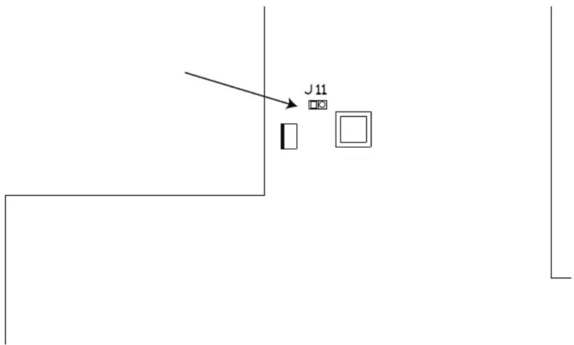
- Power on the Serial Console Server.
- When the LEDs flash, power off the Serial Console Server.
-
Remove the jumper cap from J11 (SN0132CO/SN0148CO) or J17 (SN9108CO/SN9116CO/SN0108CO/SN0116CO).
-
Close the housing and start the Serial Console Server. After powering on the unit, you can use the default Super Administrator Username and Password (see First Time Setup, page 33), to log in.
Pin Assignment
The Serial Console Server has DTE/DCE auto-sensing feature to connect directly to Cisco network switches and other compatible devices.
The pin assignment for the serial ports under different mode is shown below:
DCE Mode Pin Assignment
| Pin Definition | |
| 1 | CTS |
| 2 | DSR |
| 3 | RxD |
| 4 | GND |
| 5 | GND |
| 6 | TxD |
| 7 | DTR |
| 8 | RTS |
DTE Mode Pin Assignment
| Pin Definition | |
| 1 | RTS |
| 2 | DTR |
| 3 | TxD |
| 4 | GND |
| 5 | GND |
| 6 | RxD |
| 7 | DSR |
| 8 | CTS |
DB-9/DB-25 Interface
If you wish to use DB-9 or DB-25 interface, please refer to the tables below:
DB-9
| RJ-45 Pin Signal DB-9F Pin Signal | |||
| 1 | C | T | S 7 |
| 2 | D | S | R 4 |
| 5 | GND | ||
| 3 RxD 3 TxD | |||
| 4 | G | N | D 5 |
| 6 TxD 2 RxD | |||
| 7 | D | T | R 1 |
| 6 | DSR | ||
| 8 | R | T | S 8 |
DB-25
| RJ-45 Pin Signal DB-25F Pin Signal | |||
| 1 | C | T | S |
| 2 | D | S | R |
| 5 | GND | ||
| 3 RxD 2 TxD | |||
| 4 | G | N | D |
| 6 TxD 3 RxD | |||
| 7 | D | T | R |
| 8 | DSR | ||
| 8 | R | T | S |
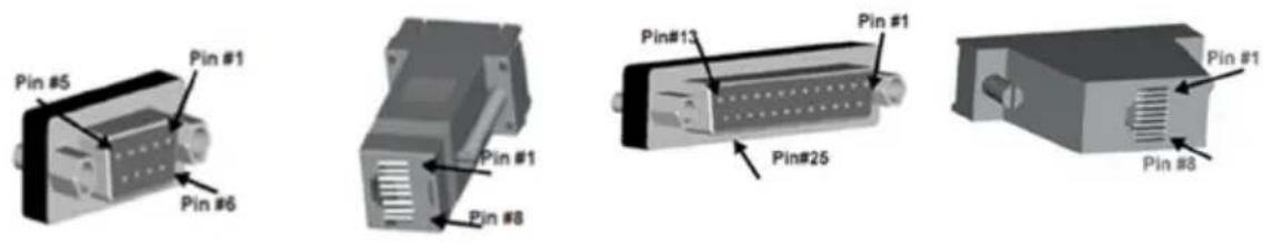
Limited Warranty
ATEN warrants its hardware in the country of purchase against flaws in materials and workmanship for a Warranty Period of two [2] years (warranty period may vary in certain regions/countries) commencing on the date of original purchase. This warranty period includes the LCD panel of ATENLCD KVM switches. Select products are warranted for an additional year (see A+ Warranty for further details). Cables and accessories are not covered by the Standard Warranty.
What is covered by the Limited Hardware Warranty
ATEN will provide a repair service, without charge, during the Warranty Period. If a product is detective, ATEN will, at its discretion, have the option to (1) repair said product with new or repaired components, or (2) replace the entire product with an identical product or with a similar product which fulfills the same function as the defective product. Replaced products assume the warranty of the original product for the remaining period or a period of 90 days, whichever is longer. When the products or components are replaced, the replacing articles shall become customer property and the replaced articles shall become the property of ATEN.
To learn more about our warranty policies, please visit our website:
http://www.aten.com/global/en/legal/policies/warranty-policy/
- EMC Information
- KCC Statement:
- Battery Safety Notice
- Telephone Support
- User Notice
- Package Contents
- SN0108CO / SN0116CO
- SN0108COD / SN0116COD
- SN0132CO / SN0148CO
- SN0132COD / SN0148COD
- SN9108CO / SN9116CO
- Contents
- Chapter 1. Introduction
- Chapter 2.Hardware Setup
- Chapter 3. Super Administrator Setup
- Chapter 4. The User Interface
- Chapter 5. Port Operating Modes
- Chapter 6. Port Access
- Chapter 7.User Management
- Chapter 8.Device Management
- Chapter 9.Log
- Chapter 10. Maintenance
- Appendix
- About This Manual
- Overview
- Conventions
- Terminology
- Features
- System Accessibility and Availability
- Serial Console Management
- Security
- System Management
- Serial Device Management
- Language
- Requirements
- DTE/DCE Auto-Sensing
- To connect to RJ45 cosole ports
- To connect to DB9 or DB25 device interface
- Browsers
- Components
- No. Component Description
- SN0132CO / SN0132COD Front View
- SN0148CO / SN0148COD Front View
- SN9108CO Front View
- SN9116CO Front View
- Reset Switch
- SN0108CO Rear View
- SN0116CO Rear View
- SN0132CO Rear View
- SN0148CO Rear View
- SN9108CO Rear View
- SN9116CO Rear View
- Before You Begin
- Stacking and Rack Mounting
- Stacking
- Rack Mounting
- Rack Mounting - Front
- Rack Mounting - Rear
- Serial Console Server Installation
- SN0108CO / SN0116CO / SN0132CO / SN0148CO Installation
- SN0108CO / SN0116CO / SN0132CO / SN0148CO Installation Diagram
- SN9108CO / SN9116CO Installation
- First Time Setup
- Local Login
- Laptop USB Console (LUC) Login - SNViewerUSB
- Console Login - HyperTerminal
- Local Console Main Menu
- Remote Login
- Telnet Login
- PuTTY Login
- Browser Login
- Setup
- Network Setup
- Changing the Super Administrator Login
- Access
- Local Console Operation
- Remote Operation
- Web Browser Login
- The Web Browser Main Page
- Page Components
- The Tab Bar
- SNViewer
- SNViewer Control Panel
- Control Panel Functions
- Data Import
- Encode
- The Message Board
- Message Display Panel
- Compose Panel
- User List Panel
- Macros
- Terminal Settings
- Terminal Application
- Telnet Menu-Driven Text UI
- PuTTY Menu-Driven Text UI
- Chapter 5
- Port Operating Modes
- Operating Mode
- Console Management
- Real COM Port
- TCP Server / TCP Client (Serial Tunnel)
- TCP Server (RAW TCP)
- TCP Client
- UDP Mode
- Virtual Modem
- Console Management Direct
- Disabled
- Chapter 6
- Port Access
- The Sidebar
- The Sidebar Tree Structure
- Filter
- Connections
- Telnet/SSH
- Port Attributes
- Favorites
- History
- Preferences
- Sessions
- Properties
- Save & Copy
- Port Buffering
- - Console Management
- Alert Strings
- Command Filters
- TCP Server
- ◆ UDP Mode
- - Console Management Direct
- ◆ Disabled
- Chapter 7
- User Management
- Users
- Adding Users
- Modifying User Accounts
- Deleting User Accounts
- Groups
- Creating Groups
- Modifying Groups
- Deleting Groups
- Users and Groups
- Assigning Users to a Group From the User's Notebook
- Removing Users From a Group From the User's Notebook
- Assigning Users to a Group From the Group's Notebook
- Removing Users From a Group From the Group's Notebook
- Device Assignment
- Assigning Device Permissions under User Settings
- Assigning Device Permissions under Group Settings
- Devices
- General
- Mounted Devices
- NFS Settings
- External USB Drive
- Syslog Settings for Port Logs
- Network
- IP Installer
- Service Ports
- Network Configuration
- ♦ Redundant NIC\*
- IPv4 Settings
- IP Address:
- DNS Server
- IPv6 Settings
- ANMS
- Log Server
- SNMP Server
- ♦ Syslog Server
- SMS Settings
- ◆ External USB Drive
- Authentication and Authorization
- ♦ RADIUS Settings
- ◆ LDAP / AD Settings
- - Kerberos
- CC Management Settings
- OOBC
- SN0108CO / SN0116CO / SN0132CO / SN0148CO
- Modem Settings
- PPP Dial In Settings
- PPP Dial Out Settings
- ISP Settings
- Dial Out Schedule
- Emergency dial out
- Mail Configuration
- Enable Dial Back
- Enable Dial Out
- Login Failures
- Security Level
- Working Mode
- IP/MAC Filter
- Account Policy
- Association
- Date/Time
- Current System Time
- New System Time
- Time Zone
- Chapter 9 Log
- System Log
- Log Notification Settings
- Backup / Restore
- Backup
- Restore
- Firmware Upgrade
- Certificates
- Private Certificate
- Certificate Signing Request
- Safety Instructions
- DC Power
- Technical Support
- International
- Specifications
- IP Address Determination
- The Local Console
- Browser
- IPv6
- Link Local IPv6 Address
- IPv6 Stateless Autoconfiguration
- Virtual Modem Details
- AT Command Set Support
- Port Forwarding
- Distance vs Baud Rate
- Clear Login Information
- Pin Assignment
- DB-9/DB-25 Interface
- Limited Warranty
- What is covered by the Limited Hardware Warranty
Brand : ATEN
Model : SN0108CO-AX-E
Category : NAS