Monte Carlo 120 X3M12S - Cap Whispair - Free user manual and instructions
Find the device manual for free Monte Carlo 120 X3M12S Whispair in PDF.

User questions about Monte Carlo 120 X3M12S Whispair
0 question about this device. Answer the ones you know or ask your own.
Ask a new question about this device
Download the instructions for your Cap in PDF format for free! Find your manual Monte Carlo 120 X3M12S - Whispair and take your electronic device back in hand. On this page are published all the documents necessary for the use of your device. Monte Carlo 120 X3M12S by Whispair.
USER MANUAL Monte Carlo 120 X3M12S Whispair
natural_image
Black-and-white portrait of a woman with long hair, hand press her finger to lips down (no text or symbols visible)whispair
AIR ENGINEERED
OPERATING AND INSTALLATION INSTRUCTIONS
FOR WHISPAIR RANGEHOODS
UTILISING REMOTE FAN MOTOR UNITS
| spair | whispair | whispair | whispair |
| whispair | whispair | whispair | whispair |
| whispair | whispair | whispair | whispair |
| whispair | whispair | whispair | whispair |
| whispair | whispair | whispair | whispair |
| whispair | whispair | whispair | whispair |
| whispair | whispair | whispair | |
| whispair | whispair | whispair | |
| whispair | whispair | whispair | |
| whispair | whispair | whispair | |
| whispair | whispair | whispair | |
| whispair | whispair | whispair | |
| whispair | whispair | whispair | |
| whispair | whispairs | whispairs | |
| whispair | whispairs | whispairs | |
| whispairs | whispairs | whispairs | |
| whispairs | whispairs | whispairs | |
| whispairs | whispairs | whispairs | |
| whispairs | whispairs | whispairs | |
| whispairs | whispairs | whispairs | |
| whispairs | whispairs | whispairs | |
| whispairs | whispairs | whispairs |
text_image
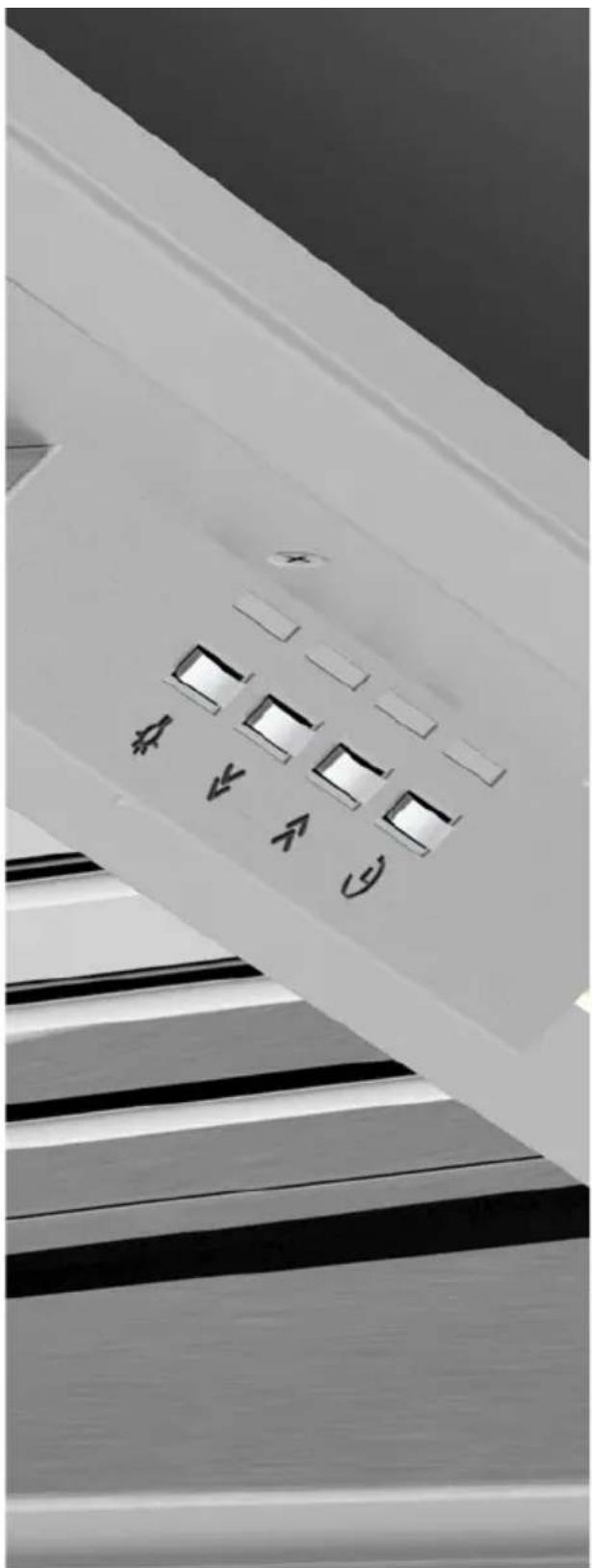
Black-and-white photo of a ceiling-mounted electronic component with multiple labeled buttons and directional arrows indicating function keys.ENVIRONMENTAL TIP
Information on disposal for users
Most of the packing materials are recyclable. Please dispose of those materials through your local recycling depot or by placing them in a appropriate collection bin.
If you wish to discard this product, please contact your local authorities and ask for the correct method of disposal.
CONGRATULATIONS
Congratulations and thank you for choosing a Whispair rangehood.
To avoid the risks that are always present when you use an electrical appliance it is important that the rangehood is installed correctly and that you read the safety instructions carefully to avoid misuse and hazards.
We recommend that you keep this instruction booklet for future reference and pass it on to any future owners.
IMPORTANT INFORMATION
AFTER UNPACKING THE RANGEHOOD PLEASE REVIEW YOUR NEW ITEM TO ENSURE THAT IT HASN'T BEEN DAMAGED IN TRANSIT OR IS MISSING ANY COMPONENTS. FAILURE TO REPORT ANY ISSUE WITHIN 72 HOURS OF RECEIPT OF YOUR ITEM MAY RESULT IN ADDITIONAL CHARGES.

natural_image
Repeating pattern of black rectangular bars on white background (no text or symbols)TO AVOID THE RISK OF INJURY OR DAMAGE TO THE PRODUCT IT IS ESSENTIAL TO READ THESE INSTRUCTIONS PRIOR TO INSTALLATION AND USE

natural_image
Row of identical black rectangular shapes on white background (no text or symbols)CARTON 1 - HOOD UNIT
You will be supplied with one of the four hood unit options detailed below.
OPTION 1 - INTEGRATED HOOD
MODELS INCLUDED:
X3M06S5, X3M09S5, X3M12S5, X3MD09S5, X3MD12S5 and X3W12S5
INCLUDED IN THE CARTON:
- Main hood housing including switch control and led lighting
- Baffle filters
- Grease trap
- Cabinet installation screws
- Operating & installation guide
OPTION 2 - WALL HUNG CANOPY HOOD
MODELS INCLUDED:
X5L09S5, X5S09S5, X5V09S5, X5R09S5, X5R09W5, X5M10S5, X5V12S5, X5N12S5 and X5N15S5
INCLUDED IN THE CARTON:
- Main hood housing including switch control and led lighting
- Baffle filters
- Grease trap
- Stainless steel chimney (2x)
- Chimney bracket
- Wall mounting bracket
- Fixing screws
- Operating & installation guide
OPTION 3 - ISLAND HUNG CANOPY HOOD
MODELS INCLUDED:
X7C12S5, X7P04B5, X7P04W5, X7S09S5, X7V09S5, X7R09S5 and
X7N12S5 INCLUDED IN THE CARTON:
- Main hood housing including switch control and led lighting
- Baffle filters
- Grease trap
- Stainless steel chimney (1x)
- Ceiling (island) mounting plate
- Mounting Beams (2x)
- Threaded rod (4x) and nuts
- Fixing screws
- Operating & installation guide
OPTION 4 - CEILING MOUNT CASSETTE AND UNIVERSAL HUNG HOOD
MODELS INCLUDED:
X9C12S5, X9B12S5, X9B15S5 and X5C10S5
INCLUDED IN THE CARTON:
- Main hood housing including switch control and led lighting
- Baffle filters
- Grease trap
- Mounting Beams (2x)
- Threaded rod (4x) and nuts
- Fixing screws
- Operating & installation guide
CARTON 2 - FAN MOTOR UNIT
You will be supplied with one of the two fan motor unit options detailed below.
OPTION 1 - INLINE FAN SOLUTION (FIG. A)
MODELS INCLUDED:
IL-800 and IP-1140
Unit designed to be located in a roof space and then ducted to an external vent to the outside atmosphere.
INCLUDED IN THE CARTON:
- KLEENAIR Inline fan motor unit
- Mounting bracket
- Mounting screws for vent and fan motor unit
- Pipe Clamps - 200mm (4x)
- 200mm Flexi-duct (5 meters in length)
- Aluminium powder coated wall / eave vent
- Foam liner for wall / eave installation

natural_image
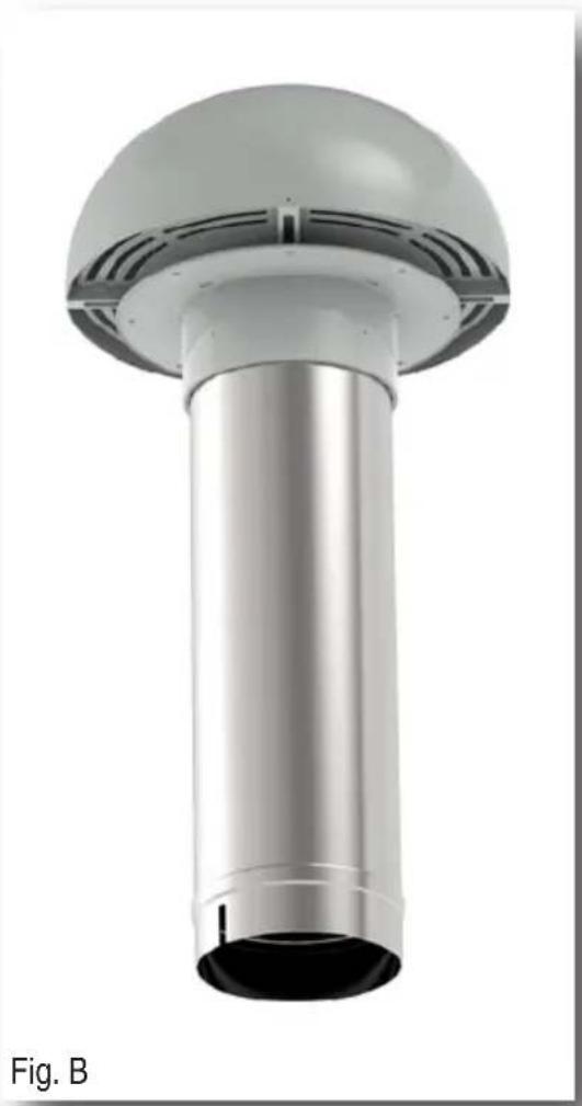
3D rendering of a mechanical component with a circular opening and flanged side (no text or symbols visible)OPTION 2 - EXTERNAL FAN SOLUTION (FIG. B)
MODELS INCLUDED:
EL-800, EP-1140 and EPP-2010.
Unit designed to be mounted externally either on an external wall vertically mounted or penetrating through the roof horizontally mounted.
INCLUDED IN THE CARTON:
- KLEENAIR External fan motor unit
- Pipe Clamps - 200mm (2x)
- 200mm Flexi-duct (5 meters in length)
- Mounting screws for wall installation
- Foam liner for wall installation
OPTIONAL INSTALLATION ACCESSORIES:
- HBX200TILE - 200mm Tile Roof Install Kit Includes roof flashing for tile roof, 200mm duct mounting brackets (2x), threaded rod (2x) and nuts (4x).
- HBX200MET - 200mm Metal Roof Install Kit Includes roof flashing for metal roof, 200mm duct mounting brackets (2x), threaded rod (2x) and nuts (4x).
- HBX200DUCT - 200mm Duct Extension Kit Includes 200mm Flexi-duct (5 meters length), 200mm inner connector and pipe clamps (2x).
natural_image
3D rendering of a metallic cylindrical pipe or duct with a dome-shaped top, labeled 'Fig. B' (no text or symbols on the structure itself)This rangehood is a domestic appliance which has been manufactured and tested to comply with Australian and New Zealand Standard AS/NZS 60335.2.31 and is designed to work under Australian and New Zealand conditions. The hoods are designed to remove bi-products of cooking – heat, steam, grease and odour.
This appliance is intended for domestic application only. Any other usage is at the owner's risk and could be dangerous. The manufacturer cannot be held liable for damage resulting from incorrect or improper use or operation. This unit is approved for electrical safety (Please refer RCM E4759).
WHISPAIR reserves the right to change the specification without notice.
All WHISPAIR performance figures are based upon standards developed by the Haus Group, which either comply or are in excess of the government regulated standards.

natural_image
A row of evenly spaced black rectangular bars on white background (no text or symbols)SAFETY
WARNING: The installation of WHISPAIR rangehoods must comply with the information in this guide. Failure to install the rangehood in accordance with these installation instructions may result in electrical hazards, injury, damage to your appliance and loss of warranty. Specifically, failure by the installer to install the screws or fixing devices in accordance with these installation instructions may result in electrical hazards. Please install the appliance as detailed in these instructions.
This appliance is not intended for use by persons (including children) with reduced physical, sensory or mental capabilities, or lack of experience and knowledge, unless they have been given supervision or instruction concerning use of the appliance by a person responsible for their safety.
Children should be supervised to ensure that they do not play with the appliance.
There shall be adequate ventilation of the room when the range hood is used at the same time as appliances burning gas or other fuels (not applicable to appliances that only discharge the air back into the room).
Exhausted air must not be discharged into a chimney or flue which may carry combustion products from other sources.
There is a fire risk if cleaning is not carried out in accordance with the instructions.
√ Baffle filters and grease trap must be regularly cleaned to reduce the risk of fire.
CAUTION: Accessible parts may become hot when used with cooking appliances and stainless steel baffle filter edge's can be sharp when handling and cleaning.
√ Ensure the rangehood is switched off and power source cable unplugged before carrying out maintenance, to avoid any possibility of electric shock.
√ Always use non-flammable materials to minimize the risk of fire.
Do not flambé under the range hood.
√ Always cover lit gas burners with pots or pans when cooker hood is in use.
If the supply cord is damaged, it must be replaced by the manufacturer, its service agent or similarly qualified persons in order to avoid a hazard.
√ Please ensure the hood is securely fixed to the support as detailed in this guide. The method of fixing stated is not to depend on the use of adhesives as they are not a means of reliable fixing.
The height of the underside of the hood body must be a minimum of 600mm above an electric cooktop, for a gas cooktop a minimum of 600mm above the highest part of the highest burner and a minimum height of 1200mm above BBQ cookers. If the instructions of the hob specify a greater distance than the minimum detailed, this shall be the minimum height for installation.

natural_image
A row of evenly spaced black rectangular shapes on white background (no text or symbols)WHISPAIR ducting is designed to ensure optimum performance for your rangehood. Please follow the installation instructions carefully.
Every WHISPAIR rangehood must be ducted to the Inline or Externally mounted KLEENAIR fan motor unit by the use of non-flammable ducting. The rangehood must not be ducted into a wall cavity or a ceiling space where a build-up of grease can occur and become a potential fire risk. Ensure the external outlet on the KLEENAIR unit is not covered and the air flow is not restricted in any way as this may result in reduced performance.
The duct must at all times have a cross sectional surface area equivalent to the hood outlet. The hood outlet has a circular cross section of 200mm in diameter or an approximate area of 31,400mm ^2 . Do not reduce the duct size at any time and avoid sharp bends. If the duct run is longer than six (6) metres, it may be necessary to enlarge the duct size to ensure optimum performance. The manufacturer does not guarantee performance when the duct length is greater than six (6) metres.
Ensure that all ducting is correctly fitted and sealed with pipe clips, duct tape or silicone to ensure that fumes do not escape prior to reaching the KLEENAIR fan motor unit.
The WHISPAIR extraction calculations are based upon a 50pa change of head of pressure loss and are used to factor the variance of air flow resistance through the ducting. 50pa is equivalent to approximately four (4) metres (the recommended length) of flexi ducting with one gentle bend, which is above and beyond the industry standard of one straight metre of ducting. The KLEENAIR LITE offers a powerful 800 cubic metres per hour (223 litres per second) of air movement. The KLEENAIR PRO offers 1140 cubic metres per hour (317 litres per second) whilst for serious users the KLEENAIR PRO PLUS boasts a market leading 2010 cubic metres per hour (558 litres per second).

THE RECOMMENDED DUCT LENGTH (INSTALLATION DISTANCE) IS 4 METRES.
THE MINIMUM INSTALLATION DISTANCE IS 3.5 METRES.
GENTLE BENDS IN THE DUCTING ARE RECOMMENDED AS IT ASSISTS IN MUFFLING NOISE FROM THE REMOTE FAN UNIT.

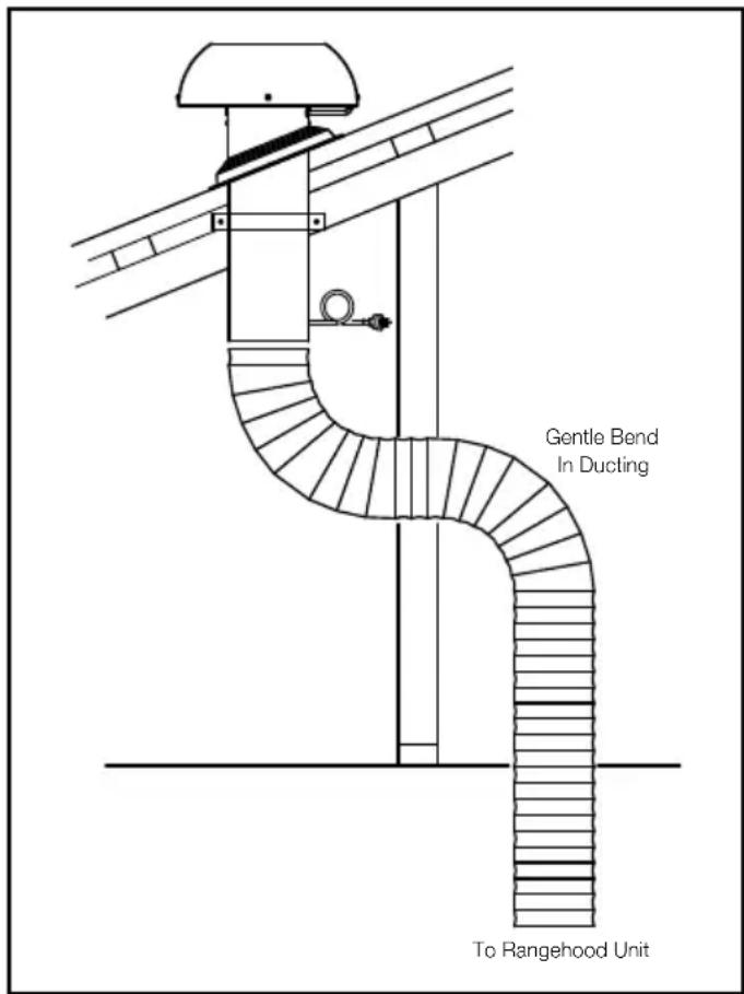
text_image
Gentle Bend In Ducting To Rangehood UnitAll KLEENAIR fan motor unit operates at maximum external sound pressure level between 43dB(A) and 76dB(A). The internal operation of the systems will have a varying sound level dependent on the style of hood, the motor option selected, the acoustics of the environment and the installation method used. It was established through testing, in accordance with the Australian Standards, that the internal noise level varied between 33dB(A) and 65dB(A) on the air movement settings available.
It is important to understand that whilst WHISPAIR rangehoods offer quieter operational noise levels due to the positioning of the motor remotely to the primary cooking environment, the noise levels as a consequence of air movement or 'wind' noise are equivalent to other premium hoods in the Australian and New Zealand market place, although it must be noted that the extraction levels are significantly higher.
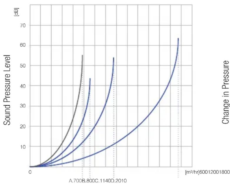
Extraction Level versus Noise Level
line
| [m³/hr] | Sound Pressure Level [dB] | Change in Pressure [m³/hr]60012001800 | | ------- | ------------------------- | ------------------------------------- | | 0 | 0 | 0 | | 2.7 | ~5 | ~3 | | 5.4 | ~25 | ~15 | | 8.1 | ~55 | ~45 | | 10.8 | ~45 | ~35 | | 13.5 | ~65 | ~60 |Cubic Meters / Hour of Air Movement
Extraction Level Comparison
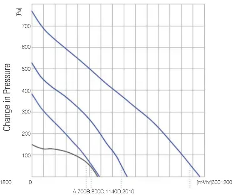
line
| Time (m³/hr) | Change in Pressure (Pa) | | ------------ | ------------------------ | | 0 | 750 | | 600 | 530 | | 1200 | 390 | | 1800 | 150 |Cubic Meters / Hour of Air Movement
A. Standard premium rangehood found in the Aus/NZ market offering 700 m ^3 /hr
B. KleenAir Lite Unit offering 800 m³/hr
C. KleenAir Pro Unit offering 1140 m³/hr
D. KleenAir Pro Plus Unit offering 2010 m³/hr
SERVICING
The installation and fitting of the rangehood should be done in such a way that will allow the unit to be removed if service is required. Additional costs incurred in the removal, such as damage to walls, are not covered under warranty.
It is expected that the stainless steel is cleaned with a quality non-abrasive stainless steel cleaner. The baffle filters and grease trap are removable and dishwasher safe. It is recommended that these items be cleaned regularly.
The KLEENAIR unit should be checked regularly to ensure that nothing is obstructing the air flow from the housing.
Integrated Hood
Models included: X3M06S5, X3M09S5, X3M12S5, X3MD09S5, X3MD12S5 and X3W12S5

natural_image
A row of evenly spaced black rectangular shapes on white background (no text or symbols)WARNING
DIMENSIONS ARE ACCURATE AT THE TIME OF PRINTING, HAUS GROUP RESERVES THE RIGHT TO CHANGE SPECIFICATIONS WITHOUT NOTICE. FOR BUILDING PURPOSES THE UNIT SHOULD BE PROVIDED TO THE CABINET MAKER / BUILDER / KITCHEN DESIGNER FOR EXACT MEASUREMENTS.

natural_image
A row of evenly spaced black rectangular shapes on white background (no text or symbols)STEP 1:
To install into your overhead cupboard, several holes may need to be cut into shelves to enable the ducting to exit the cabinetry. Ensure the hood is mounted as close to the centre of the cooking surface as possible.
NOTE:
The height of the underside of the hood body must be a minimum of 600mm above an electric cooktop, for a gas cooktop a minimum of 600mm above the highest part of the highest burner and a maximum height of 1000mm. If the instructions of the hob specify a greater distance than the minimum detailed, this shall be the minimum height for installation.
A comfortable installation height would be 700 - 750mm gap between the base of the rangehood and the highest part on your cooktop.
For installation over a BBQ, the hood must be installed a minimum of 1200mm above the cooking surface. Building codes that stipulate a minimum dimension may vary from state to state, please check with your local council prior to installation.
STEP 2:
Refer to Part 2: Motor Installation Guide.
STEP 3:
Remove the three (3) screw fixings from within the Main Chassis of the rangehood located along the rear chassis wall (located above the grease trap), along with two (2) screws on the left side and two (2) screws on the right side. Once the screws are removed, the Fascia will separate away from the Main Chassis.
STEP 4:
Fixing Holes are located on the returns of the main chassis. These Fixing Holes are used to secure the main chassis to the cabinetry.
STEP 5:
Place the Main Chassis in the cabinet ensuring that the hood is level and the controls and display will be visible when standing in front of the unit.
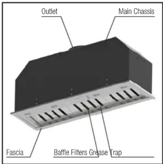
text_image
Outlet Main Chassis Fascia Baffle Filters Grease Trap
text_image
Step 3: Remove Fascia from Chassis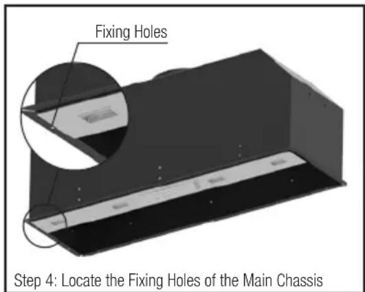
text_image
Fixing Holes Step 4: Locate the Fixing Holes of the Main ChassisSTEP 6:
Using the ten (10) fixing holes, screw the Main Chassis into position.
STEP 7:
Once the Main Chassis is secured into the cabinetry, the Fascia can then be slid back inside the Main Chassis. Replace the screws (removed in Step 3) to fix the Fascia back into positon.
STEP 8:
Attach the male power plug of the rangehood unit to mains power supply. Note to electricians: Standard 10 Amp General Power Outlet (GPO) required. Position GPO as close to the hood unit as possible.

text_image
Step 7: Insert Fascia into Main ChassisINSTALLING THE GREASE TRAP AND BAFFLE FILTERS:
All WHISPAIR hoods utilise removable baffle filters and grease trap. This filtration system is used to catch by-products such as grease and moisture from the air flow.
To install the baffle filters, simply locate the filter on the top ledge of the hood and then slide the filter on a downward angle to rest in the channel of the grease trap. Ensure the filter vane are aligned towards the rear of the hood.
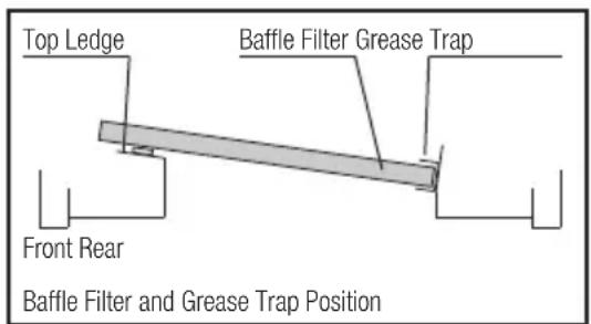
text_image
Top Ledge Baffle Filter Grease Trap Front Rear Baffle Filter and Grease Trap PositionMost by-products are captured and stored directly in the baffle filters however the grease trap may begin to fill when excess amounts of grease and condensate build up in the filter vanes.
The grease trap can be removed for cleaning by removing the two (2) screw fixings in the channel.
To clean your baffle filters and grease trap please wash with warm soapy water or simply place in the dishwasher for convenience. Please note, baffle filter edge's can be sharp and caution must be taken when removing and when cleaning by hand.
It is recommended the baffle filters and grease trap are cleaned every 4 weeks to reduce the risk of fire.
Wall Hung Canopy Hood
Models included: X5L09S5, X5S09S5, X5V09S5, X5V12S5, X5R09S5, X5R09W5, X5M10S5 and X5N12S5

natural_image
A row of evenly spaced black rectangular shapes on white background (no text or symbols)WARNING
DIMENSIONS ARE ACCURATE AT THE TIME OF PRINTING, HAUS GROUP RESERVES THE RIGHT TO CHANGE SPECIFICATIONS WITHOUT NOTICE. FOR BUILDING PURPOSES THE UNIT SHOULD BE PROVIDED TO THE CABINET MAKER / BUILDER / KITCHEN DESIGNER FOR EXACT MEASUREMENTS.

natural_image
A row of identical black rectangular shapes on white background, no text or symbols present.STEP 1:
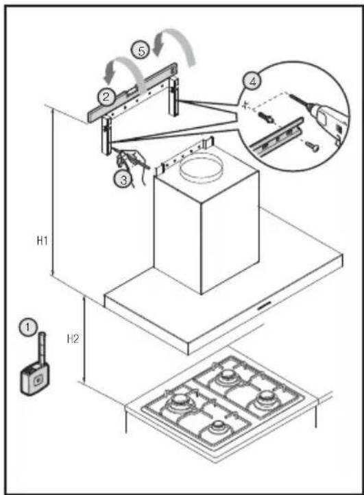
Measure the height (H1) of the hood from the base to the top of the Mounting Hooks. Ensure the hood is mounted as close to the centre of the cooking surface as possible.
NOTE:
The height (H2) of the underside of the hood body must be a minimum of 600mm above an electric cooktop, for a gas cooktop a minimum of 600mm above the highest part of the highest burner and a maximum height of 1000mm. If the instructions of the hob specify a greater distance than the minimum detailed, this shall be the minimum height for installation.
A comfortable installation height would be 700 - 750mm gap between the base of the rangehood and the highest part on your cooktop.
For installation over a BBQ, the hood must be installed a minimum of 1200mm above the cooking surface. Building codes that stipulate a minimum dimension may vary from state to state, please check with your local council prior to installation.
STEP 2:
Using a spirit level mark a vertical centre line on the wall where the Mounting Bracket needs to be positioned. It is recommended to centre the hood unit to the cooktop below.
STEP 3:
Mark a horizontal line on the wall for the Mounting Bracket position. Centre and mark the four (4) fixing points in the vertical section on the left and right side of the bracket. Drill and plug holes with suitable sized wall plugs (not provided).
STEP 4:
Fix the Mounting Bracket with four (4) suitable screws into the wall at the positions marked in step 3 to allow the body of the hood to be hung on the wall.
STEP 5:
Hang the hood on the wall ensuring the Mounting Hooks are securely positioned into the Mounting Bracket.
text_image
Technical diagram of a mechanical testing setup with labeled components and motion indicators
text_image
Wall Mounting Bracket Hood Fixing Holes (5x) - Step 6 Wall Fixing Holes (4x) - Step 4STEP 6:
Secure the hood to the wall by screw fixing through the five (5x) holes on the horizontal plate of the Mounting Bracket.
STEP 7:
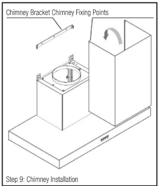
Secure the Chimney Bracket to the wall.
STEP 8:
Refer to Part 2: Motor Installation Guide.
STEP 9:
Place the stainless steel chimney on the hood and secure to the Chimney Bracket with the two (2) screws supplied. If the chimney is required to be shortened, new holes may need to be drilled to secure the chimney cover.
STEP 10:
Attach the male power plug of the rangehood unit to mains power supply. Note to electricians: Standard 10 Amp General Power Outlet (GPO) required. Position GPO as close to the hood unit as possible.
text_image
Chimney Bracket Chimney Fixing Points Step 9: Chimney InstallationINSTALLING THE GREASE TRAP AND BAFFLE FILTERS:
All WHISPAIR hoods utilise removable baffle filters and grease trap. This filtration system is used to catch by-products such as grease and moisture from the air flow.
To install the baffle filters, simply locate the filter on the top ledge of the hood and then slide the filter on a downward angle to rest in the channel of the grease trap. Ensure the filter vane are aligned towards the rear of the hood.

text_image
Top Ledge Baffle Filter Grease Trap Front Rear Baffle Filter and Grease Trap PositionMost by-products are captured and stored directly in the baffle filters however the grease trap may begin to fill when excess amounts of grease and condensate build up in the filter vanes.
The grease trap can be removed for cleaning by removing the two (2) screw fixings in the channel.
To clean your baffle filters and grease trap please wash with warm soapy water or simply place in the dishwasher for convenience. Please note, baffle filter edge's can be sharp and caution must be taken when removing and when cleaning by hand.
It is recommended the baffle filters and grease trap are cleaned every 4 weeks to reduce the risk of fire.
Island Hung Canopy Hood
Models included: X7C12S5, X7P04B5, X7P04W5, X7S09S5, X7V09S5, X7R09S5, X7R09W5 and X7N12S5

natural_image
A row of evenly spaced black rectangular shapes on white background (no text or symbols)WARNING
DIMENSIONS ARE ACCURATE AT THE TIME OF PRINTING, HAUS GROUP RESERVES THE RIGHT TO CHANGE SPECIFICATIONS WITHOUT NOTICE. FOR BUILDING PURPOSES THE UNIT SHOULD BE PROVIDED TO THE CABINET MAKER / BUILDER / KITCHEN DESIGNER FOR EXACT MEASUREMENTS.

natural_image
A row of identical black rectangular shapes on white background, no text or symbols present.STEP 1:
Using a weighted string line (plumb line), determine the central position of hood on the ceiling. Ensure the hood is mounted as close to the centre of the cooking surface as possible. Mark the position. Before making the cut out, check for obstructions like electrical cables, etc.
NOTE:
The height of the underside of the hood body must be a minimum of 600mm above an electric cooktop, for a gas cooktop a minimum of 600mm above the highest part of the highest burner and a maximum height of 1000mm. If the instructions of the hob specify a greater distance than the minimum detailed, this shall be the minimum height for installation.
A comfortable installation height would be 700 - 750mm gap between the base of the rangehood and the highest part on your cooktop.
For installation over a BBQ, the hood must be installed a minimum of 1200mm above the cooking surface. Building codes that stipulate a minimum dimension may vary from state to state, please check with your local council prior to installation.
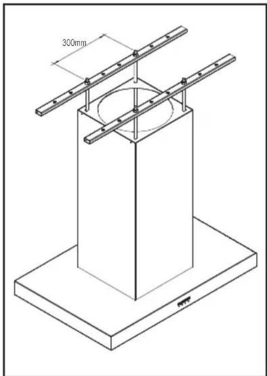
STEP 2:
Place the two (2) supplied supporting metal beams (1000mm long) with pre-drilled fixing holes perpendicular (90°) to the roof trusses.
STEP 3:
Fit the four (4) supplied 10mm threaded rod through the holes provided on the supporting metal beams and secure with nuts and washers provided. Ensure the rod drop height is sufficient to attach the hood and nut fixings but is not excessive that is will impede the placement of the filters.
STEP 4:
Feed the Ceiling Plate up the threaded rod and fix into position with nuts provided ensure a firm fit to the ceiling.
STEP 5 (OPTIONAL):
For additional stability add a second Ceiling Plate (optional) half way between the ceiling and the hood. This will give the mounting additional stability which may be beneficial for longer chimney runs.
text_image
300mm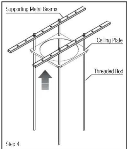
text_image
Supporting Metal Beams Ceiling Plate Threaded Rod Step 4STEP 6:
Refer to Part 2: Motor Installation Guide.
STEP 7:
Lift the stainless steel chimney into position and secure to the Ceiling Bracket with the four (4) screws supplied. If the chimney is required to be shortened, new holes may need to be drilled to secure the chimney cover.
STEP 8:
Attach the flexi-ducting to the top of the hood unit and fix into place with a stainless steel clamp (provided).
STEP 9:
Lift and attach the hood unit to the base of the threaded rod with the provided nuts and washers. Level the unit off by tensioning the 10mm nuts. Being mindful not to over tighten. Minimise how much threaded rod is below the nut. Excess threaded rod may interfere with the baffle filters.
STEP 10:
Feed any excess flexi-ducting back into the ceiling space ensuring that any excess gathering of ducting is pulled tight. Loose and gathered ducting will reduce the extraction levels.
STEP 11:
Attach the male power plug of the rangehood unit to mains power supply. Note to electricians: Standard 10 Amp General Power Outlet (GPO) required. Position GPO as close to the hood unit as possible.
INSTALLING THE GREASE TRAP AND BAFFLE FILTERS:
All WHISPAIR hoods utilise removable baffle filters and grease trap. This filtration system is used to catch by-products such as grease and moisture from the air flow.
To install the baffle filters, simply locate the filter on the top ledge of the hood and then slide the filter on a downward angle to rest in the channel of the grease trap. Ensure the filter vane are aligned towards the rear of the hood.
Most by-products are captured and stored directly in the baffle filters however the grease trap may begin to fill when excess amounts of grease and condensate build up in the filter vanes.
The grease trap can be removed for cleaning by removing the two (2) screw fixings in the channel.
To clean your baffle filters and grease trap please wash with warm soapy water or simply place in the dishwasher for convenience. Please note, baffle filter edge's can be sharp and caution must be taken when removing and when cleaning by hand.
It is recommended the baffle filters and grease trap are cleaned every 4 weeks to reduce the risk of fire.

text_image
Lift Chimney Into Position (Step 7) Lift Hood Into Position (Step 9)
text_image
Hood Mounting Points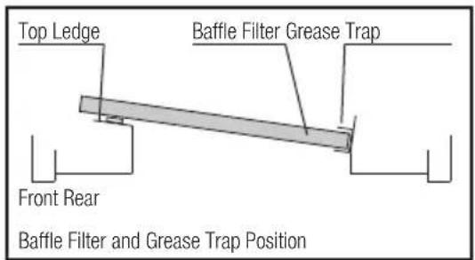
text_image
Top Ledge Baffle Filter Grease Trap Front Rear Baffle Filter and Grease Trap PositionCeiling Mounted Cassette and Universal Hung Hood
Models included: X9C12S5, X9B12S5, X9B15S5 and X5C10S5

natural_image
A row of evenly spaced black rectangular shapes on white background (no text or symbols)WARNING
DIMENSIONS ARE ACCURATE AT THE TIME OF PRINTING, HAUS GROUP RESERVES THE RIGHT TO CHANGE SPECIFICATIONS WITHOUT NOTICE. FOR BUILDING PURPOSES THE UNIT SHOULD BE PROVIDED TO THE CABINET MAKER / BUILDER / KITCHEN DESIGNER FOR EXACT MEASUREMENTS.

natural_image
A row of identical black rectangular shapes with no text or symbolsSTEP 1:
Using a weighted string line (plumb line), determine the central position of hood on the ceiling. Ensure the hood is mounted as close to the centre of the cooking surface as possible. Mark the position. Before making the cut out, check for obstructions like electrical cables, etc.
NOTE:
The height of the underside of the hood body must be a minimum of 600mm above an electric cooktop, for a gas cooktop a minimum of 600mm above the highest part of the highest burner. If you are installing a BBQ Alfresco specific model above a BBQ it must be installed at a minimum 1200mm above the BBQ cooking surface. The maximum recommended height for a cassette unit is 1500mm above the cooktop. If the instructions of the hob specify a greater distance than the minimum detailed, this shall be the minimum height for installation.
Building codes that stipulate a minimum dimension may vary from state to state, please check with your local council prior to installation.
STEP 2:
Place the two (2) supplied supporting metal beams (500mm long) with pre-drilled fixing holes perpendicular (90°) to the roof trusses.
STEP 3:
Fit the four (4) supplied 10mm threaded rod through the holes provided on the supporting metal beams and secure with nuts and washers provided. Ensure the rod drop height is sufficient to attach the hood and nut fixings but is not excessive that is will impede the placement of the filters.
STEP 4:
Refer to Part 2: Motor Installation Guide.
STEP 5:
Attach the flexi-ducting to the top of the hood unit and fix into place with a pipe clamp (provided).

natural_image
Technical line drawing of a rectangular structural frame with mounting holes and vertical supports (no text or symbols)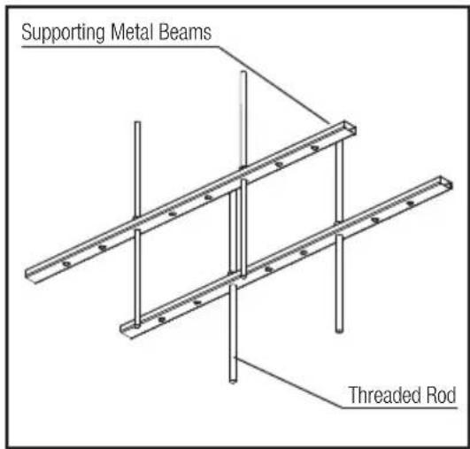
text_image
Supporting Metal Beams Threaded RodPART 1: HOOD INSTALLATION GUIDE
STEP 6:
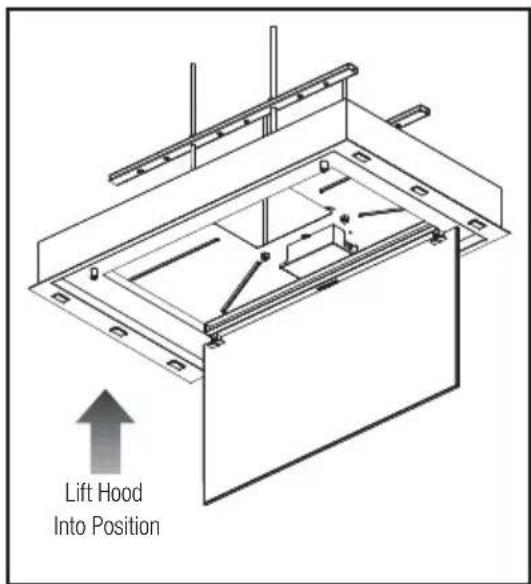
Lift and attach the hood unit to the base of the threaded rod with the provided nuts and washers. Secure the hood cassette firmly to the underside of the ceiling. Level the unit off by tensioning the 10mm nuts. Being mindful not to over tighten. Minimise how much threaded rod is below the nut. Excess threaded rod may interfere with the baffle filters.
STEP 7:
Feed any excess flexi-ducting back into the ceiling space ensuring that any excess gathering of ducting is pulled tight. Loose and gathered ducting will reduce the extraction levels.
STEP 8:
Attach the male power plug of the rangehood unit to mains power supply. Note to electricians: Standard 10 Amp General Power Outlet (GPO) required. Position GPO as close to the hood unit as possible.
text_image
Lift Hood Into PositionINSTALLING THE GREASE TRAP AND BAFFLE FILTERS:
All WHISPAIR hoods utilise removable baffle filters and grease trap. This filtration system is used to catch by-products such as grease and moisture from the air flow.
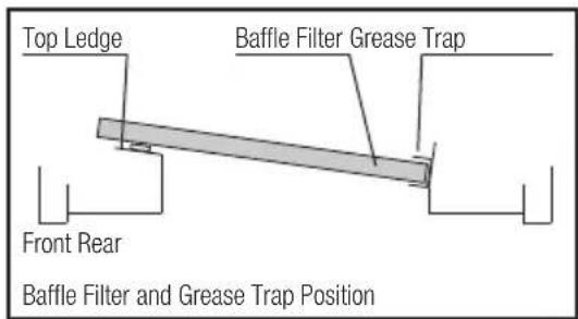
To install the baffle filters, simply locate the filter on the top ledge of the hood and then slide the filter on a downward angle to rest in the channel of the grease trap. Ensure the filter vane are aligned towards the rear of the hood.
text_image
Top Ledge Baffle Filter Grease Trap Front Rear Baffle Filter and Grease Trap PositionMost by-products are captured and stored directly in the baffle filters however the grease trap may begin to fill when excess amounts of grease and condensate build up in the filter vanes.
The grease trap can be removed for cleaning by removing the two (2) screw fixings in the channel.
To clean your baffle filters and grease trap please wash with warm soapy water or simply place in the dishwasher for convenience. Please note, baffle filter edge's can be sharp and caution must be taken when removing and when cleaning by hand.
It is recommended the baffle filters and grease trap are cleaned every 4 weeks to reduce the risk of fire.
PART 2: FAN MOTOR INSTALLTION GUIDE

EXTERNAL KLEENAIR
MOTOR SOLUTION
Roof (Upper) and
Wall (Lower) Mounted

natural_image
Technical line drawing of a curved pipe or duct system with structural components (no text or symbols)Roof
Flashing to suit
Metal or Tile Roof
(Optional Accessory)
Housing Mounts
(Optional Accessory)
Fan Power Supply
Attached to Internal Hood Unit
Ducting Pulled Tight
Gentle Bend In Ducting
200mm Ducting
Attached to Internal
Hood Unit Outlet
text_image
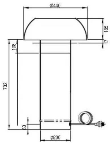
Ø440 185 17 108 702 30 Ø200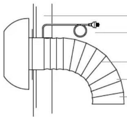
natural_image
Technical line drawing of a curved pipe or duct with internal divisions and a valve (no text or symbols)Wall
Fan Power Supply
Attached to Internal Hood Unit
Gentle Bend In Ducting
Ducting Pulled Tight
200mm Ducting
Attached to Internal Hood Unit Outlet

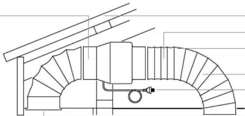
INLINE KLEENAIR
MOTOR SOLUTION
Eave (Upper) and
Wall (Lower) Vented
natural_image
Technical line drawing of a mechanical assembly with no visible text or symbolsRoof
Ducting Pulled Tight
200mm Ducting
Attached to Internal Hood Unit Outlet
Gentle Bend In Ducting
Fan Power Supply
Attached to Internal Hood Unit
Vent & Eave

text_image
390 200 159 30 70 314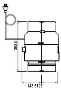
text_image
363.5 143.5125
natural_image
Technical line drawing of a mechanical component with curved internal structure and pipe connection (no text or symbols)Wall
Fan Power Supply
Attached to Internal Hood Unit
Gentle Bend In Ducting
Ducting Pulled Tight
200mm Ducting
Attached to Internal
Hood Unit Outlet
Vent
Inline Solution
Models included: IL-800 and IP-1140
Positioning your KLEENAIR Unit:
It is recommended that the KLEENAIR INLINE unit be mounted in a roof space or wall cavity. Please ensure that the KLEENAIR unit is positioned in an environment that is free of other gases to enable an efficient expulsion of the cooking by-products and to ensure that back draft of external gases doesn't take place.
Please ensure the fan motor is positioned away from other exhausts such as chimneys, gas flues, etc. The inline unit can be mounted so that it ducts directly through the wall or eave vent.
STEP 1:
Establish a suitable position in the roof or wall cavity for the KLEENAIR unit, ensuring that the distance between the KLEENAIR unit and the outside vent is no greater than 800mm. The KLEENAIR unit must be located a minimum of 3 metres from the hood unit.
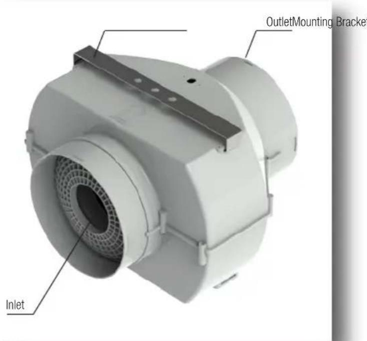
text_image
Inlet OutletMounting BracketSTEP 2:
Using the mounting bracket and screws, mount the KLEENAIR unit to a beam, truss or another appropriate structures in the roof or wall space through the rubber grommets. Hang the fan motor unit from the mounting bracket ensuring the mounting bracket is located at the top of the unit. Ensure the direction of airflow is toward the outside. The direction of airflow is marked on the KLEENAIR unit.
STEP 3:
Cut a 200mm diameter hole in the wall or eave to enable the mounting of the external vent. Please ensure that the hole is cut in a practical position to enable the flexi-duct to be secured. Attach the flexi-duct to the vent and then mount vent to the wall or eave.
STEP 4:
Attach the flexi-duct from the external vent to the outlet of the KLEENAIR unit using pipe clamps. To minimise inefficiencies and noise ensure the duct is pulled tight and the 200mm diameter is maintained.
STEP 5:
Attach flexi-duct from the KLEENAIR unit to the rangehood using pipe clamps. Ensure that the duct is pulled tightly to ensure that flexi-duct remains firm and stable during operation. Avoid sharp bends in the duct. Gentle bends in the ducting are recommended as it assists in muffling noise from the fan motor unit back to the rangehood. If the flexi-duct needs to be extended attach two flexi-duct ends using a rigid duct insert and secured by pipe clamps (Optional installation accessories HBX200DUCT).
STEP 6:
Attach the male plug of the KLEENAIR unit to the female plug of the rangehood to enable power supply to the fan motor unit. An extension lead (not supplied) of up to five meters may be added if required.
External Solution - Wall Mounted
Models included: EL-800, EP-1140 and EPP-2010
Positioning your KLEENAIR Unit:
It is recommended that when the KLEENAIR EXTERNAL UNIT is WALL mounted, it is positioned a minimum 1800mm above the ground surface with a downward clearance of 1200mm and with a radial clearance of 600mm. Please ensure that the KLEENAIR unit is positioned in an environment that is free of other gases to enable an efficient expulsion of the cooking bi-products and to ensure that back-draft of external gases doesn't take place.
Please ensure the fan motor is positioned away from other exhausts such as chimneys, gas fuses, etc. The unit can be mounted so that it ducts directly through the wall.
STEP 1:
Cut a 200mm diameter hole in the wall to enable the rigid duct on the back of the KLEENAIR unit to protrude. Please ensure that the hole is cut in a practical position to enable sufficient clearance around the fan motor unit.
STEP 2:
Remove the mounting bracket from your KLEENAIR unit by twisting the cover in an anti-clockwise direction. Mark at least four mounting points on the wall and pre-drill the holes required.
STEP 3:
The rigid duct may require cutting to suit your particular wall thickness. Attach the flexi-duct to the rigid duct on the back of the mounting bracket using the pipe clamps supplied.
STEP 4:
Fix the mounting bracket to the wall using the screws and wall plugs provided. Making sure to secure it at 90 degree's to the horizontal. A secondary mounting bracket (X1K.EWM) is available is additional clearance between the wall and outlet is required.
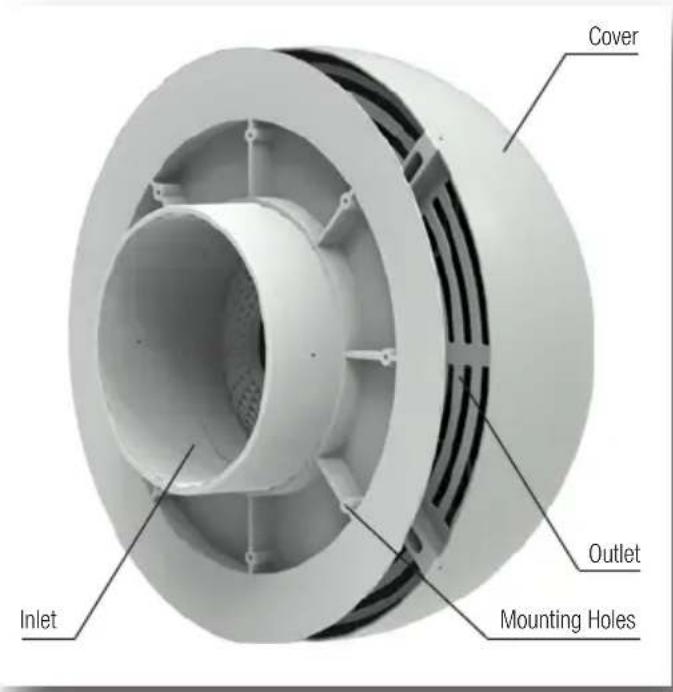
text_image
Cover Inlet Outlet Mounting Holes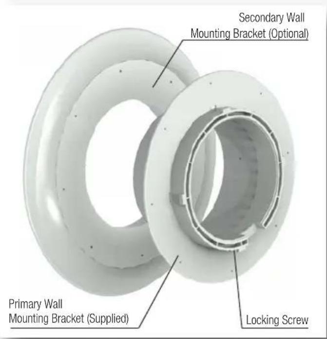
text_image
Secondary Wall Mounting Bracket (Optional) Primary Wall Mounting Bracket (Supplied) Locking ScrewSTEP 5:
Feed the power cable through the centre of the mounting bracket and return the KLEENAIR unit onto the mounting bracket and fix it by rotating the cover in a clockwise direction noting the locating points. Lock the cover into position by tightening the locking screw.
STEP 6:
Attach the male plug of the KLEENAIR unit to the female plug of the rangehood to enable power supply to the fan motor unit. An extension lead (not supplied) of up to five meters may be added if required.
External Solution - Roof Mounted
Models included: EL.800, EP.1140 and EPP.2010
Positioning your KLEENAIR Unit:
It is recommended that when the KLEENAIR EXTERNAL UNIT is ROOF mounted, it is positioned a minimum 2100mm above the ground surface with a radial clearance of 600mm. Please ensure that the KLEENAIR unit is positioned in an environment that is free of other gases to enable an efficient expulsion of the cooking by-products and to ensure that back-draft of external gases doesn't take place.
Please ensure the fan motor is positioned away from other exhausts such as chimneys, gas fuses, etc. The unit can be mounted so that it ducts directly through the roof and is mounted below the highest point of the roof line.
STEP 1:
Cut a 200mm diameter hole in the roof to enable the rigid duct on the base of the KLEENAIR unit to protrude down into the roof space. Please ensure that the hole is cut in a practical position to enable sufficient clearance around the fan motor unit. Affix the flashing (optional accessory X1IK.200TILE or X1IK.200MET) to the roof surface. Please ensure that the flashing is sealed thoroughly onto the rigid duct with silicone to prevent water leaks.
STEP 2:
Using standard 200mm pipe mounts (optional accessory), mount the rigid duct to beams, trusses or other appropriate structures in the roof space. Ensure the rigid duct protrudes past the top of the flashing by at least 75mm.
STEP 3:
Remove the mounting bracket from your KLEENAIR unit by rotating the cover in an anti-clockwise direction.
STEP 4:
Fix the mounting bracket to the rigid duct using the screws provided.
STEP 5:
Feed the power cable through the centre of the mounting bracket and return the KLEENAIR unit on to the mounting bracket and fix it by rotating the cover in a clockwise direction. Lock the cover into position by tightening the locking screw, which is located between the outlet and the mounting bracket.
STEP 6:
Attach the flexi-duct to the rigid duct using the pipe clamps supplied.
STEP 7:
Attach flexi-duct from the KLEENAIR unit to the rangehood using pipe clamps. Ensure that the duct is pulled tightly to ensure that flexi-duct remains firm and stable during operation. Avoid sharp bends in the duct. Gentle bends in the ducting are recommended as it assists in muffling noise from the fan unit back to the rangehood. If the flexi-duct needs to be extended, attach the two flexi-duct ends using a rigid duct insert, secured by pipe clamps or duct tape. (Optional Accessory - X1IK.200DUCT)
STEP 8:
Attach the male plug of the KLEENAIR unit to the female plug of the rangehood to enable power supply to the fan motor unit. An extension lead (not supplied) of up to five meters may be added if required.

text_image
Mounting Bracket Outlet Rigid Duct Inlet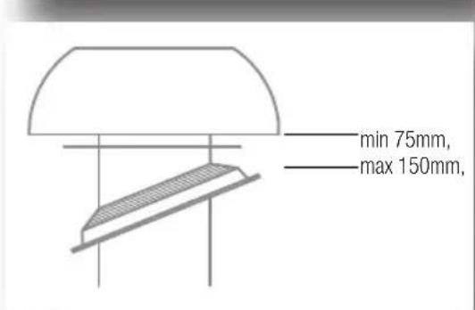
text_image
min 75mm, max 150mm,Operating your 4-button control panel
Models included: Electronic Control or Touch Control
TURNING THE EXTRACTION FUNCTION ON OR OFF:
- In standby mode, press button 2 or 3 to change the speed.
- The hood has three speed options and a 4th boost speed (4 speeds in total).
- The LED indicators directly above the buttons indicates the speed setting selected.
- To turn hood off, press button 2 repeatedly until hood returns to standby mode.
- Auto off function: After 2 hour of operation without alteration the fan motor will turn off (returned to standby).
TURNING THE LIGHT FUNCTION ON OR OFF:
Press button 1 to turn on or turn off the light independently in standby mode.
TURNING THE TIMER FUNCTION ON OR OFF:
In operating mode, press button 4 to engage the timer function, then press button 2 or 3 to adjust the delay time.
The default timer is set to 10mins and can be increased in increments of 10mins up to 1 hour (i.e. 4 pushes of button 3 will result in timer set to 50mins before shut off).
When the timer is first activated, the LED positioned behind button 4 (timer) will flash quickly to indicate the time setting i.e. for 30mins remaining the LED will blink 3 times quickly. When the timer function is engaged the (timer) LED positioned behind button 4 (timer) will blink slowly until the timer expires.

flowchart
graph TD
    A["Sun"] --> B["Down"]
    B --> C["Up"]
    C --> D["Down"]
    D --> E["1"]
    E --> F["2"]
    F --> G["3"]
It is recommended that your WHISPAIR rangehood and all of its items be cleaned regularly. Before any cleaning or maintenance work, disconnect the cooker hood from the mains power supply.
CLEANING THE STAINLESS STEEL HOOD UNIT
- It is expected that the stainless steel is cleaned with a quality non-abrasive stainless steel cleaner.
- Use a soft cloth for application.
- It is recommended that this is performed every 4 weeks.
CLEANING THE KLEENAIR FAN MOTOR UNIT
- The KLEENAIR unit should be checked regularly to ensure that nothing is obstructing the air flow from the housing.
- If there are obstructions, please remove the debris ensuring the product returns to the manufacturer's intended operating condition.
CLEANING THE BAFFLE FILTERS AND GREASE TRAP
- The baffle filters and grease trap can be removed from the mounted position within the hood and washed in the dishwasher or by hand.
- Use hot water and liquid detergent.
• After cleaning, leave the filters and trap to dry before placing back in the hood.
WARNING WHEN CHANGING THE LED LAMP
Please be aware that whilst in use LED lighting units may become hot and the surrounding area may remain hot for some time after switching off. Please allow the lamp area to cool before operating near the lighting.
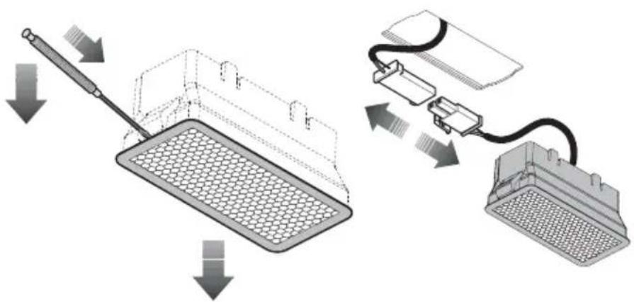
REPLACEMENT OF LED LAMP
• Make sure the main power supply into hood is disconnected at the GPO.
- Using a fine flat blade, wedge the LED unit from the insert whilst applying pressure to the locking tab.
- Disconnect the 12V connectors.
- Replace with a new unit and push back inside the cut outs in the fascia.
- Please replace only with a genuine unit available from Haus Group Australia Pty Ltd.
natural_image
Diagram showing a filtration device with a handle and connected to an electrical connector (no text or symbols present)WARRANTY
Every WHISPAIR rangehood comes with a 5-Year parts and labour warranty. This warranty is conditional upon the appliance being used only for personal, domestic and household purposes and installed and operated in accordance with WHISPAIR instructions.
The consumer is responsible for any charges associated with removal of the faulty unit and installation of the new unit.
The customer may also be responsible for any freight charges incurred in this change over process.
The installation of WHISPAIR rangehoods must comply with the information in the guide. Installation of the rangehood must be in a covered area, to avoid direct weathering. Failure to follow the guidelines will result in loss of warranty.
We recommend our customers use an authorised WHISPAIR installer.
Any imperfections in the finishes or in the natural materials used should not be considered as faults but a typical characteristic of these crafted products.
Should you ever need to make a warranty related enquiry about your WHISPAIR product, in Australia simply call Haus Group Australia on +61 (0) 3 8593 9600 or New Zealand on +64 (0) 9 887 6959 to speak with our friendly customer service team consultants. We suggest you have the following information close at hand to make the process as easy as possible:
- Model number of your complete rangehood and motor unit
- A copy of your WHISPAIR proforma invoice
- Address details of where the appliance has been installed
Any associated or ancillary costs to be incurred by you as a result of replacement or repair of your WHISPAIR rangehood under this guarantee shall, in all cases, be previously approved by Haus Group Australia Pty Ltd.
Please note: The benefits provided under this warranty are additional to other rights and remedies available to the customer under the Australian Customer Law.
YOUR STATUTORY RIGHTS
Our goods come with guarantees that cannot be excluded under the Australian Consumer Law. You are entitled to a replacement or a refund for a major failure and for compensation for any other reasonably foreseeable loss or damage. You are also entitled to have the goods repaired or replaced if the goods fail to be of acceptable quality and the failure does not amount to a major failure.
NOTES
NOTES
| whispair | whispair | whispair | whispair |
| whispair | whispair | whispair | whispair |
| whispair | whispair | whispair | whispair |
| whispair | whispair | whispair | whispair |
| whispair | whispair | whispair | whispair |
| whispair | whispair | whispair | whispair |
| whispair | whispair | Whispair | whispair |
| whispair | whispair | whispair | whispair |
| whispair | whispair | whispair | whispair |
| whispair | whispair | whispair | whispair |
| whispair | whispair | whispair | whispair |
| whispair | whispair | whispair | whispair |
| Whispair | whispair | whispair | whispair |
| whispair | whispair | whispair | whispair |
| whispair | whispair | whispair | whispair |
Print Version: W_16_S5_01
haus.
head office
Haus Group Australia Pty Ltd
2/2 Network Drive
CARRUM DOWNS Victoria Australia 3201
Australia
t. (AU) 03 8593 9600 f. (AU) 03 8593 9699
e. info@hausgroup.com.au