Power Pix DWC-D3361WTIR - Security Camera Digital Watchdog - Free user manual and instructions
Find the device manual for free Power Pix DWC-D3361WTIR Digital Watchdog in PDF.


| Product Type | Indoor Dome IR Camera |
| Image Sensor | 1/3" 760H CMOS Sensor Chip (760 Horizontal Pixels) |
| Horizontal Resolution | 690 TV Lines |
| Minimum Illumination | 0.0 Lux (F1.2, 30IRE) |
| S/N Ratio | 58dB (AGC off) |
| Lens Type | Varifocal Auto Iris Lens (2.8~12mm) |
| IR Distance | 100ft (30m) |
| Day/Night | True Day & Night with IR Cut Filter (TDN) |
| Wide Dynamic Range | Yes (WDR: Low/Middle/High) |
| Noise Reduction | 2D Digital Noise Reduction (2D DNR, Level 1~3) |
| Shutter Speed | 1/60~1/66,000 sec (Auto) |
| White Balance | ATW / OUTDOOR / INDOOR |
| Video Output | CVBS: 1.0Vp-p / 75Ω (BNC) |
| Power Requirement | Dual Voltage: 12VDC or 24VAC (Auto Sensing) |
| Power Consumption (IR off/on) | DC12V: 1.8W/4.3W; AC24V: 1.8W/4.3W |
| Operating Temperature | -10°C to 50°C (14°F to 122°F) |
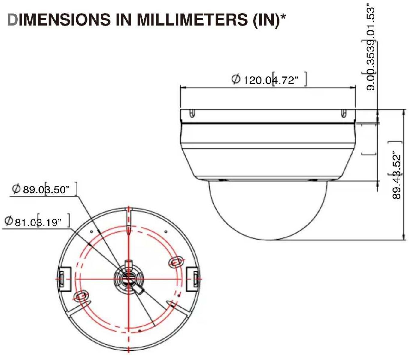
| Dimensions (Ø x H) | 120 x 89.4 mm (4.7 x 3.52 in) |
| Weight | 0.5 lbs (227 g) |
| Housing Material | Plastic |
| Mounting | Wall or ceiling mount (template and screws included) |
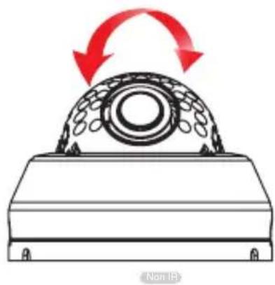
| Pan/Tilt/Rotation | 360° rotation, 360° pan, 55° (IR) / 65° (non-IR) tilt |
| Additional Features | AGC, AWB, smear cancellation, mirror (H/V), OSD joystick control |
| Warranty | 5 years (labor/parts) + 1 year on IR LEDs |
Frequently Asked Questions - Power Pix DWC-D3361WTIR Digital Watchdog
User questions about Power Pix DWC-D3361WTIR Digital Watchdog
0 question about this device. Answer the ones you know or ask your own.
Ask a new question about this device
Download the instructions for your Security Camera in PDF format for free! Find your manual Power Pix DWC-D3361WTIR - Digital Watchdog and take your electronic device back in hand. On this page are published all the documents necessary for the use of your device. Power Pix DWC-D3361WTIR by Digital Watchdog.
USER MANUAL Power Pix DWC-D3361WTIR Digital Watchdog
Indoor Dome IR Camera
DWC-D3361WTIR
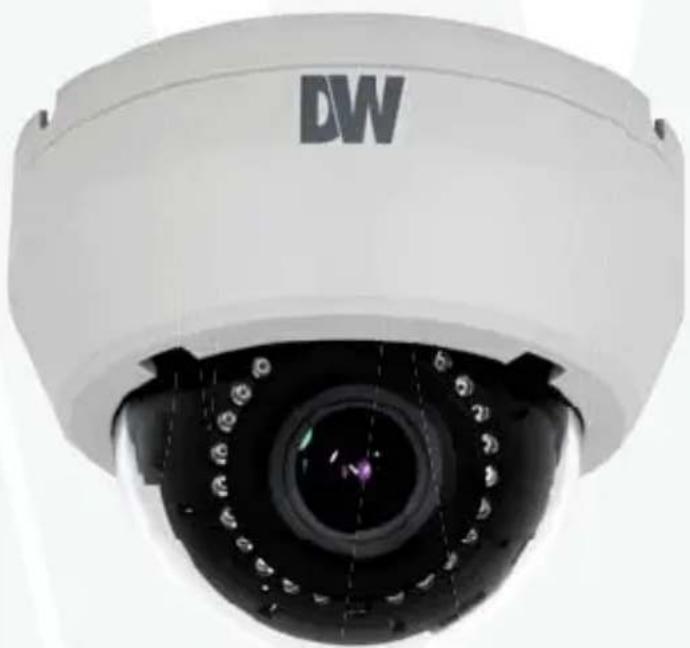
natural_image
Close-up of a white surveillance camera with 'DW' logo on the dome (no additional text or symbols visible)Power Pix
ABOUT MANUAL
Before installing and using the camera, please read this manual carefully.
Be sure to keep it handy for future reference.
12132013
PRECAUTIONS
■ Do not open or modify.
- Do not open the case except during maintenance and installation, for it may be dangerous and can cause damages.
■ Do not put objects into the unit.
- Keep metal objects and flammable substances from entering the camera.
It can cause fire, short-circuits, or other damages.
■ Be careful when handling the unit.
■ To prevent damages, do not drop the camera or subject it to shock or vibration.
■ Do not install near electric or magnetic fields.
■ Protect from humidity and dust.
■ Protect from high temperature.
- Be careful when installing near the ceiling of kitchen or a boiler room, as the temperature may rise to high levels.
■ Cleaning:
To remove dirt from the case, moisten a soft cloth with a soft detergent solution and wipe.
■ Mounting Surface:
The material of the mounting surface must be strong enough to support the camera.
FCC COMPLIANCE
This equipment has been tested and found to comply with the limits for a Class B digital device, pursuant to part 15 of the FCC rules. These limits are designed to provide reasonable protection against harmful interference, when the equipment is operated in a residential environment. This equipment generates, uses, and radiates radio frequency energy; and if it is not installed and used in accordance with the instruction manual, it may cause harmful interference to radio communications.
WARNING: Changes or modifications are not expressly approved by the manufacturer.
Table of contents
TABLE OF CONTENTS
Introduction Features 4
Parts and Descriptions 5
Dimensions 6
Installation ____ Inside the Box ____ 7
Mount Installation Instructions____ 8
Connecting to Monitors 9
Control Board 10
Adjusting the Camera Lens_ 11
Adjusting the Camera Angle 12 ____
Module OSD Menu 13-21
Troubleshooting 22
Warranty Information 23-24
Specifications 25-26
FEATURES\*
■ 1/3" 760H CMOS Sensor Chip (760 Horizontal Pixels)
690TVL
■ 2.8\~12mm Varifocal Auto Iris Lens
■ 100ft Range IR with Intelligent Camera Sync
■ TDN (True Day & Night) with IR Cut Filter
■ WDR (Wide Dynamic Range)
■ 2D DNR (2D Digital Noise Reduction)
■ Smear Cancelation
■ AGC / AWB
■ Easy Icon Driven OSD Menu with Built-in Joystick
■ Auto Sensing 24VAC/12VDC
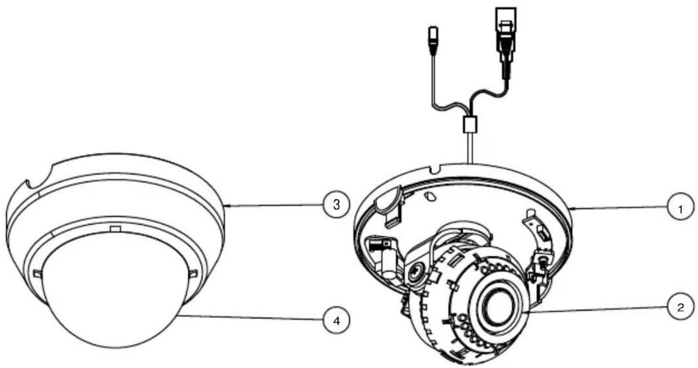
PARTS & DESCRIPTION\*
1 Bottom Case
2 Camera Gimbal
3 Upper Case
4 Dome Cover
other
| Dimension | Value | | ----------------- | ------------ | | Diameter (in inches) | 89.0 | | Width (in inches) | 81.0 | | Height (in inches) | 120.0 | | Thickness (in inches) | 9.0 | | Total Diameter | 120.0 | | Total Height | 89.4 |INSIDE THE BOX\*
Included with your Camera
1 User Manual
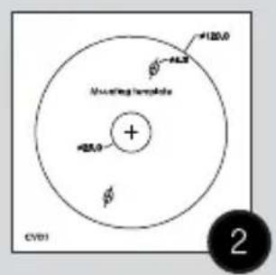
2 Mounting Template
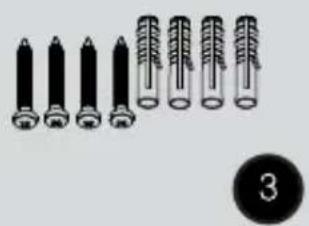
3 4 Machine Screws and 4 Dry Wall Anchors
4 L-Key
5 Secondary Video-BNC Cable
natural_image
Illustration of multiple cylindrical objects with metallic tips, arranged in two rows (no text or symbols)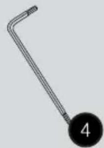
natural_image
Simple line drawing of a bent tool with a circular label containing the number 4 (no text or symbols on the tool itself)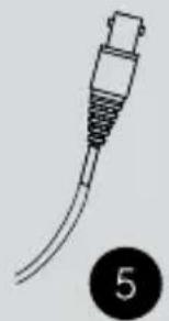
natural_image
Line drawing of a cable or connector with a looped end, labeled with number 5 (no text or symbols on the diagram itself)EASY INSTALLATION\*
natural_image
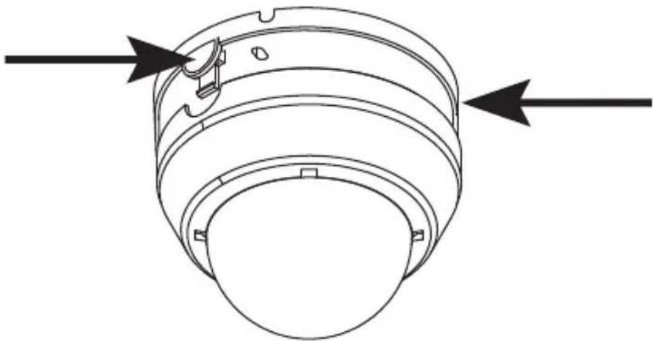
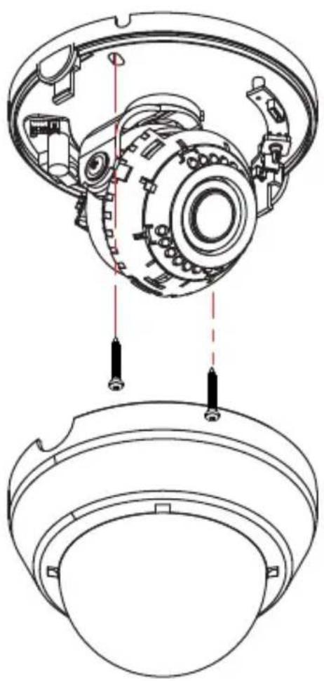
Technical line drawing of a cylindrical mechanical component with two directional arrows indicating flow or movement (no text or symbols)- To detach the camera's cover dome from the camera's module press the small buttons located at the sides of the cover dome. While pressing the buttons, disconnect the cover dome from the camera's base module.
- Use the camera or mounting template to mark and drill the necessary holes in the wall or ceiling.
- Pull wires through and make connections.
- Using the two (2) included screws, mount and secure the camera to the wall or ceiling.
- Adjust the camera's Pan and Tilt. See page 12 for more information.
- Use the joystick to adjust the OSD menu. See pages 13-21 for more information.
- Snap the camera's cover dome to the camera base to complete the installation.
natural_image
Technical diagram of a mechanical assembly showing internal components and mounting features (no text or labels)CONNECTING TO MONITORS\*
Use the diagram below to connect to a Monitor or CRT Monitor properly.
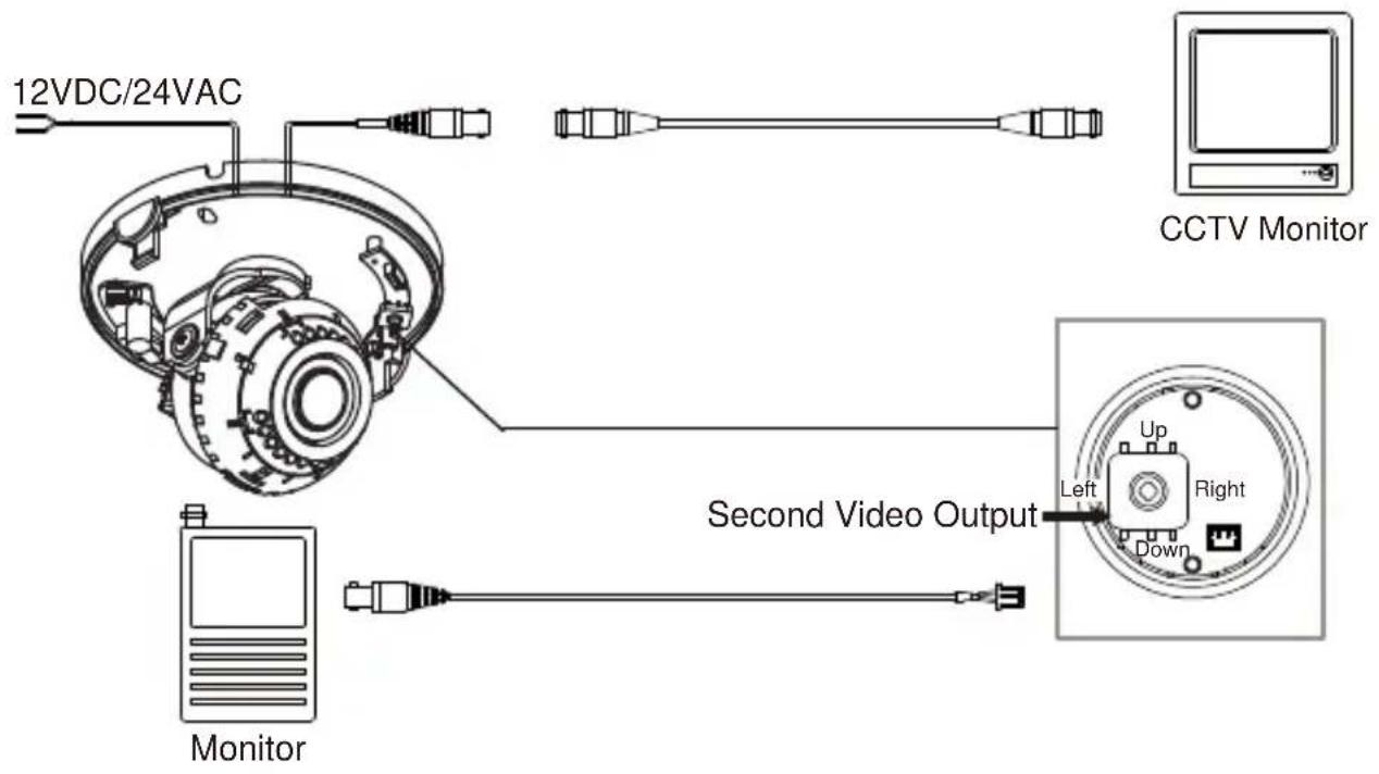
■ Power Connection - 12VDC/24VAC Dual Voltage (Auto Polarity Detection and Protection)
■ All cameras are equipped with a second video output for on-site configuration.
CONTROL BOARD*
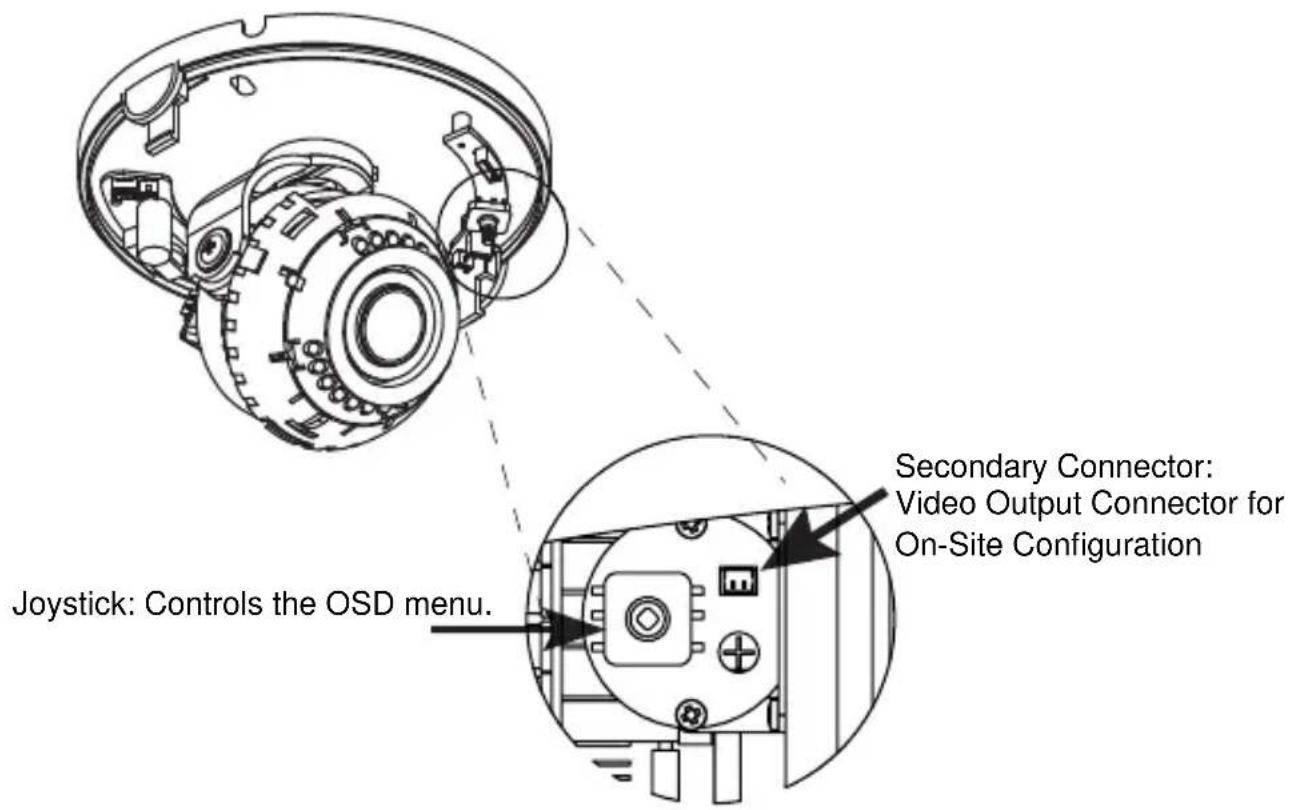
1 Remove the camera's lens cover by rotating it counter-clockwise.
② Use the Joystick to control the camera's OSD options.
ADJUSTING THE CAMERA LENS\*
Follow the instructions provided below to make any lens adjustments.
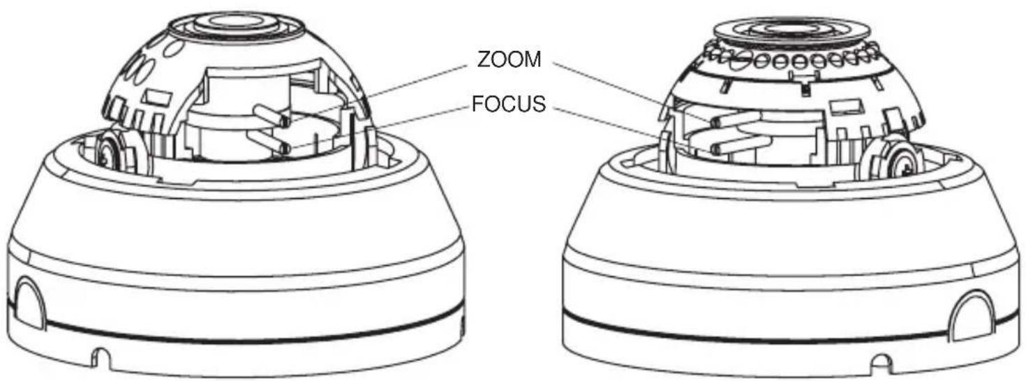
Non IR
Zoom: Wide ⇔ - → Tele
Focus: Far ⇔ - → Near
IR
To adjust the field of view, use the L-Key to turn the zoom screw (located on the bottom of the camera) counter-clockwise to zoom in, or clockwise to zoom out.
2 Adjust the focus the same way as described above AFTER the desired zoom position is established.
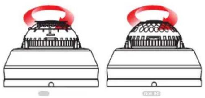
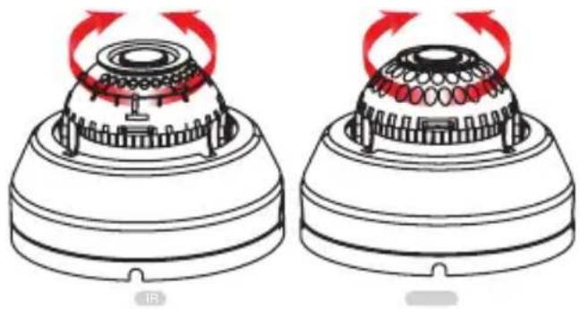
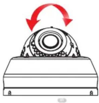
ADJUSTING THE CAMERA GIMBAL*
natural_image
Two identical diagrams showing a device with red light emitting a circular component, labeled 'Non-IRI' below (no text or symbols on the devices themselves)1 Rotation 360^
natural_image
Diagram of two mechanical components with red arrows indicating rotation or force direction (no text or symbols)2 Panning 360^
natural_image
Mechanical component diagram showing a rotating assembly with red arrows indicating rotational motion (no text or symbols)3 Tilting 55° IR LED
natural_image
Diagram of a mechanical bearing assembly with red arrows indicating rotational motion (no text or symbols)3 Tilting 65°
MODULE OSD MENU*
| EXPOSURE COLOR | DAY & NIGHT | |
 |  |  |
| SETUPFUNCTION | EXIT | |
 |  |  |

EXPOSURE
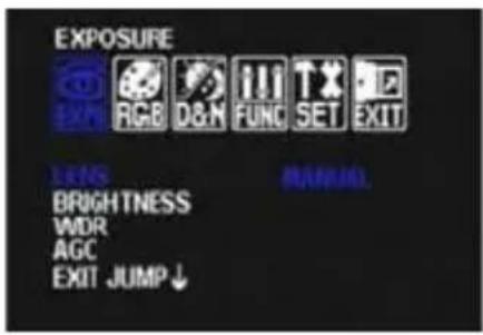
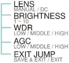
LENS
Manual Manual mode supports the fixed board lens or the manual iris lens.
DC DC mode supports the auto-iris varifocal lens.
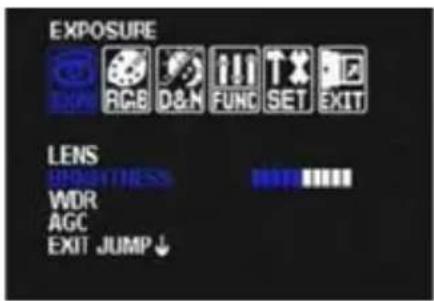
BRIGHTNESS
Adjust the camera's brightness from 0\~10. The higher the number, the brighter the image will appear.

EXPOSURE
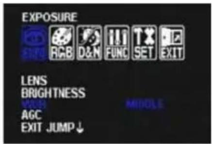
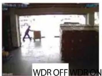
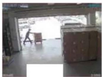
WDR (Wide Dynamic Range)
Enables the camera to capture clear images even when there are both very bright and very dark areas in the camera's field of view. Select from the following options: LOW / MIDDLE (Default) / HIGH.
natural_image
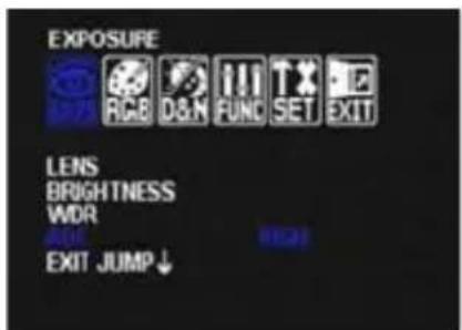
Interior view of a warehouse or storage room with a person walking through the doorway and stacked boxes on the floor (no visible text or symbols)AGC (Auto Gain Control)
AGC enhances the picture brightness in low light conditions. A higher level AGC setting makes the images brighter; however, it could increase the amount of noise. Set the AGC level from the following options: LOW / MIDDLE / HIGH (Default).

COLOR
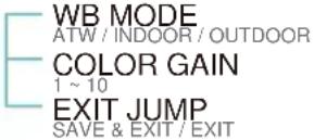
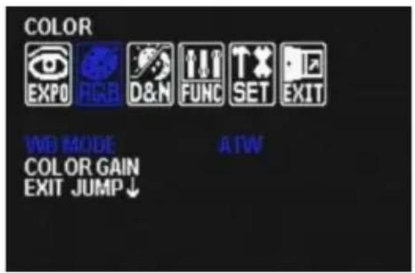
WB MODE
ATW Set as the camera's default value. Auto Tracking White Balance Control mode compensates for color temperature changes between 2500K and 9500K.
OUTDOOR Select this option if the camera is to be mounted outside in an open area.
INDOOR Select this option if the camera is to be mounted inside a closed area.
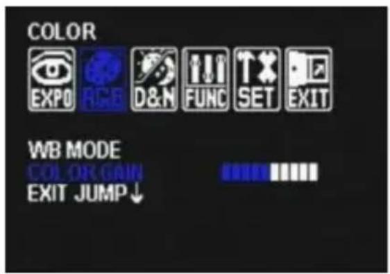
COLOR GAIN
Set the Color Gain level from 1\~10.

DAY & NIGHT
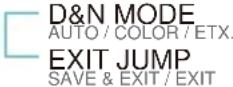
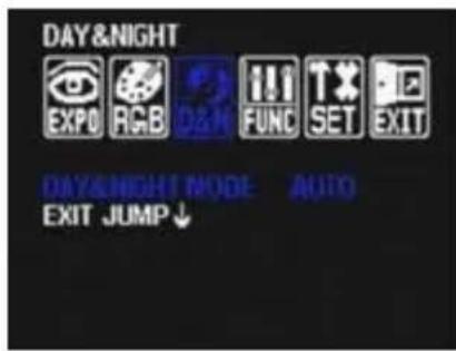
D&N MODE
AUTO In AUTO mode, camera switches between day and night automatically depending on light level.
COLOR If COLOR is selected, camera always stays in day/color mode.
EXT For best IR LEDs performance, select this option as default.

FUNCTION
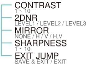
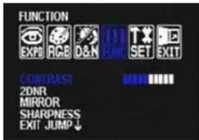
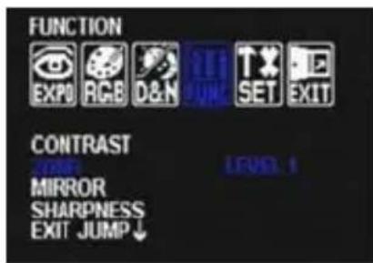
CONTRAST
1\~10 Set the level of contrast. The higher the contrast, the brighter the image will appar.
The lower the contrast, the darker the image will appear.
2D DNR (Digital Noise Reduction)
2D-DNR reduces the noise on the screen in low light conditions and allows for clearer images, even at night.
Select the 2D DNR level from 1\~3 (Set to Level 1 as default).

FUNCTION
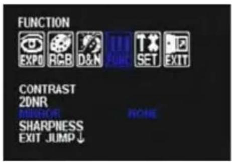
MIRROR
The mirror option allows you to flip the camera's image horizontally and vertically to adjust the camera's view after installation. Chose from the following options:
NONE / H / V / H, V.
V - Flip- turns the camera upside down.
H - Flip- Mirors the camera horizonatll.
H, V - Flip- turns the camera's image upside down and rotates is horizontally.

natural_image
Illustration of a blue teddy bear and a cartoon character with a fan-like head (no text or symbols)
natural_image
Two cartoon-style toys, one resembling a bear and the other a blue bear, displayed against a white background with a fan (no text or symbols visible)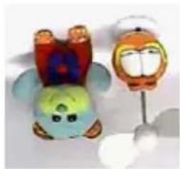
natural_image
Two cartoon-style figurines, one blue and green with a rainbow hat, the other orange and yellow with a smiling face (no text or symbols)V-FlipH - FlipNONE
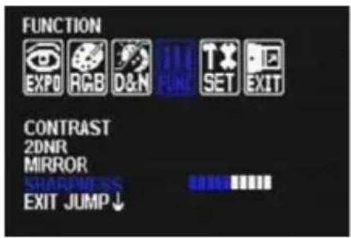
SHARPNESS
1 \~ 10 Sets the image sharpness. The higher the number, the sharper the image.

SETUP
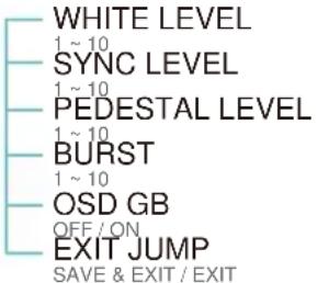
WHITE LEVEL
Adjust the camera's White Levels from 1 \~ 10. The higher the number, the stronger white colors in the camera's Field of View will appear. The camera is set by default to the optimal White Level and therefore it is recommended not to change the original settings.
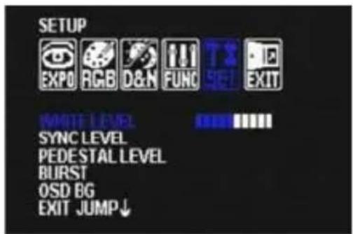
SYNC LEVEL.
Set the camera's sync signal level value from 1 to 10.1 10 The camera is set by default to the optimal sync signal and therefore it is recommended not to change the original settings.
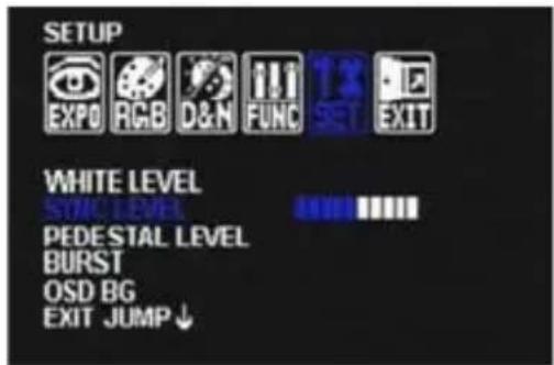
PEDESTAL LEVEL
Adjusts the camera's Brightness Levels from 1 \~ 10. The camera is set by default to the optimal Pedestal Level and therefore it is recommended not to change the original settings.


SETUP
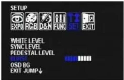
BURST
Setting the color signal level value from 1 to 10. The camera is set by default to the optimal burst level and therefore it is recommended not to change the original settings.
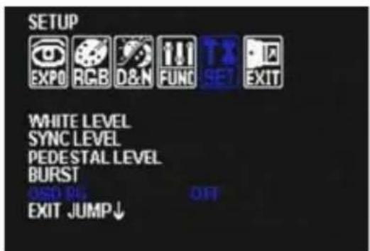
OSD BG
You can add a dark background behind the OSD to better view the OSD options when the camera's image is too bright and the OSD text is not seen properly.
If ON is selected, a semi-transparent square will appear in the center of the camera's display, allowing you to better view and manage your OSD options.

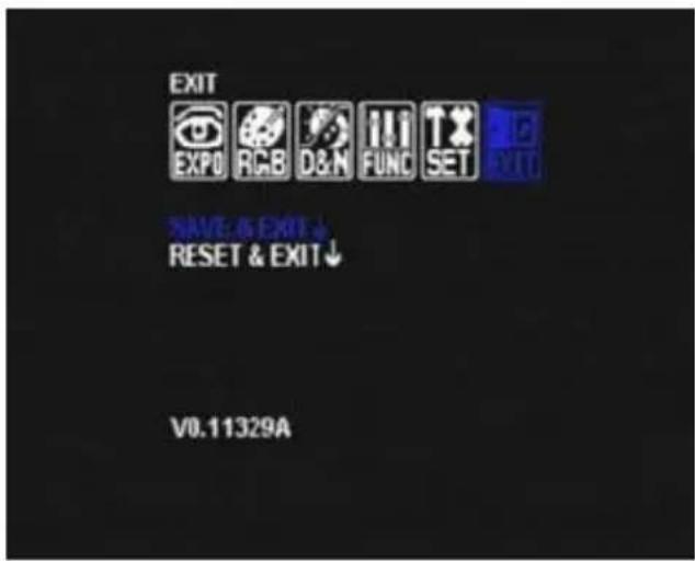
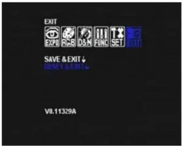
EXIT
EXIT
SAVE Exit the OSD menu after saving the recent changes.
RESET Exit the OSD menu adter resetting the camera to its default settings.
TROUBLESHOOTING
Before sending your camera for repair, check the following or contact our technical specialist.
FOR NO VIDEO
Check the coaxial cable and make sure it is connected securely.
Check the lens' iris adjustment at the camera's OSD menu.
Check the power supply and make sure the camera has the proper voltage and current.
FOR OUT-OF-FOCUS VIDEO
Check the clear dome cover and the lens for dirt or fingerprints. Use a soft cloth and gently clean. Check the lens' manual focal and zoom adjustment. The use of a field test monitor is recommended.
WARRANTY INFORMATION\*
Digital Watchdog (referred to as “the Warrantor”) warrants the Digital Watchdog Camera against defects in materials or workmanship as follows:
LABOR: For the initial five (5) years and one (1) year on IR LED from the original purchase date, if the camera is determined to be defective, the Warrantor will repair or replace the unit with a new or refurbished product at its option at no charge.
PARTS: In addition, the Warrantor will supply replacement parts for the initial five (5) years and one (1) year on IR LED.
To obtain warranty or out of warranty service, please contact a Technical Support Representative at 1-866-446-3595 Monday through Friday from 9:00AM to 8:00PM Eastern Standard Time.
A purchase receipt or other proof of the original purchase date is required before warranty service is rendered. This warranty only covers failures due to defects in materials and workmanship which arise during normal use. This warranty does not cover damage which occurs in shipment or failures which are caused by products not supplied by the Warrantor or failures which result from accident, misuse, abuse, neglect, mishandling, misapplication, alteration, modification, faulty installation, set-up adjustments, improper antenna, inadequate signal pickup, maladjustment of consumer controls, improper operation, power line surge, improper voltage supply, lightning damage, rental use of the product or service by anyone other than an authorized repair facility or damage that is attributable to acts of God.
LIMITS & EXCLUSIONS\*
There are no express warranties except as listed. The warrantor will not be liable for incidental or consequential damages (including damage to recording media without limitation) resulting from the use of these products or arising out of any breach of the warranty. All express and implied warranties, including the warranties of merchantability and fitness for particular purpose, are limited to the applicable warranty period set forth above.
Some states do not allow the exclusion or limitation of incidental or consequential damages, or limitatons on how long an implied warranty lasts, so the exclusions or limitations listed above may not apply to you. This warranty gives you specific legal rights, and you may also have other rights that vary from state-to-state.
If the problem is not handled to your satisfaction, then write to the following address:
Digital Watchdog, Inc.
ATTN: RMA Department
5436 W. Crenshaw Street
Tampa, FL 33634
Service calls which do not involve defective materials or workmanship as determined by the Warrantor, in its sole discretion, are not covered. Costs of such service calls are the responsibility of the purchaser.
SPECIFICATIONS*
| VIDEO | |
| Image Sensor 760H CMOS | |
| Total Pixels 756(H) X 504(V) | |
| Scanning System 2 : 1 Interlace | |
| Frequency 15.734KHz (H), 59.95Hz (V) | |
| Synchronization Internal | |
| Horizontal Resolution 690 TV Lines | |
| Minimum Illumination F1.2 (30IRE): 0.0 Lux | |
| S/N Ratio 58dB (AGC off) | |
| Video Output CVBS: 1.0Vp-p / 75 Ω | |
| LENS | |
| Focal Length 2.8~12 mm | |
| Lens Type Varifocal Auto Iris Lens | |
| IR Distance 100ft Range IR | |
| OPERATIONAL | |
| Shutter Speed 1/60~1/66,000, AUTO | |
| Brightness 1~10 | |
| WDR Low / Middle / High | |
| Auto Gain Control Low / Middle / High | |
| DNR Level 1 ~ 3 | |
| White Balance ATW/ OUTDOOR/ INDOOR | |
| OPERATIONAL | |
| Day and Night AUTO/ COLOR/ EXT | |
| Mirror NONE/ H/ V/ H,V | |
| Contrast 1~10 | |
| Sharpness 1 ~ 10 | |
| White Level 1~10 | |
| ENVIRONMENTAL | |
| Operating Temperature -10 | °C ~ 50°C (14°F ~ 122°F) |
| Operating Humidity Less than 90% (Non-Condensing) | |
| ELECTRICAL | |
| Power Requirement Dual Voltage (DC12V, 24VAC) | |
| Power Consumption DC12V: 1.8W, 150mA, LED On: 4.3W, 358mA | |
| AC24V: 1.8W, 75mA, LED On: 4.3W, 180mA | |
| MECHANICAL | |
| Housing Material Plastic | |
| Dimensions 120 x 89.4 mm (4.7 X 3.52 in) | |
| Weight 0.5 lbs | |
*Specification is subject to change without prior notice.
MEMO*
DW•DIGITAL WATCHDOG
Everything's Digital
5436 W Crenshaw St. Tampa, FL 33634
Tel: 866-446-3595 / 813-888-9555
Fax:813-888-9262
www.Digital-Watchdog.com
technicalsupport@dwcc.tv
Technical Support Hours : Monday-Friday
9:00am to 8:00pm EST
- Indoor Dome IR Camera
- Power Pix
- PRECAUTIONS
- FCC COMPLIANCE
- Table of contents
- FEATURES\*
- PARTS & DESCRIPTION\*
- INSIDE THE BOX\*
- Included with your Camera
- EASY INSTALLATION\*
- CONNECTING TO MONITORS\*
- ADJUSTING THE CAMERA LENS\*
- Non IR
- IR
- EXPOSURE
- LENS
- BRIGHTNESS
- WDR (Wide Dynamic Range)
- AGC (Auto Gain Control)
- COLOR
- WB MODE
- COLOR GAIN
- DAY & NIGHT
- D&N MODE
- FUNCTION
- CONTRAST
- MIRROR
- SHARPNESS
- SETUP
- WHITE LEVEL
- SYNC LEVEL.
- PEDESTAL LEVEL
- BURST
- OSD BG
- EXIT
- TROUBLESHOOTING
- FOR NO VIDEO
- FOR OUT-OF-FOCUS VIDEO
- WARRANTY INFORMATION\*
- LIMITS & EXCLUSIONS\*
- DW•DIGITAL WATCHDOG
Brand : Digital Watchdog
Model : Power Pix DWC-D3361WTIR
Category : Security Camera