DW LPR DWC-LPR650U - Security Camera Digital Watchdog - Free user manual and instructions
Find the device manual for free DW LPR DWC-LPR650U Digital Watchdog in PDF.


| Product Type | License Plate Recognition Bullet Camera |
| Brand | Digital Watchdog |
| Model | DW LPR DWC-LPR650U |
| Image Sensor | 1/3" CMOS, 2.1MP (1944x1092) |
| Resolution | 1920x1080 (1080p) at 30fps |
| Lens | 6~50mm P-Iris Varifocal |
| IR Distance | 115 ft (35 m) |
| Minimum Illumination | 0 Lux (B&W) at F1.6 |
| Video Output | BNC (Universal: HD-A/HD-TVI/HD-CVI/CVBS) |
| Shutter Speed | 1/30(25) ~ 1/30,000 sec |
| Day/Night | Black & White mode only |
| Signal-to-Noise Ratio | 55dB |
| Power Requirements | DC12V / AC24V Dual Voltage, 6.12W, 510mA |
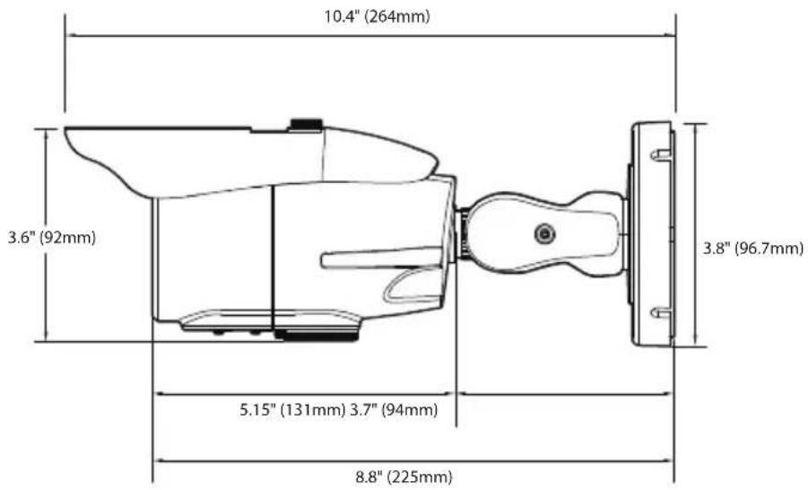
| Dimensions (Housing) | 10.4 x 3.81 in (264 x 96.7 mm) |
| Weight | 1.79 lbs (0.81 kg) |
| Operating Temperature | -4°F ~ 122°F (-20°C ~ 50°C) |
| Humidity | Up to 90% non-condensing |
| Ingress Protection | IP66 |
| Certifications | FCC, CE, ROHS |
| Warranty | 5 years (parts and labor), 1 year on IR LED |
| Key Features | LPR up to 50 mph, 13-30 ft capture range, Smart IR, Smart DNR, HME, BLC, DRC, varifocal lens, OSD via joystick/UTC |
| Cleaning Instructions | Use dry cloth; do not use liquid cleaners |
| Safety Precautions | Do not open; risk of electric shock. Use specified adapter only |
| User Serviceable Parts | None; refer servicing to qualified personnel |
Frequently Asked Questions - DW LPR DWC-LPR650U Digital Watchdog
User questions about DW LPR DWC-LPR650U Digital Watchdog
0 question about this device. Answer the ones you know or ask your own.
Ask a new question about this device
Download the instructions for your Security Camera in PDF format for free! Find your manual DW LPR DWC-LPR650U - Digital Watchdog and take your electronic device back in hand. On this page are published all the documents necessary for the use of your device. DW LPR DWC-LPR650U by Digital Watchdog.
USER MANUAL DW LPR DWC-LPR650U Digital Watchdog
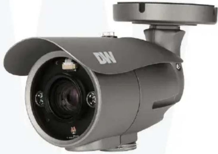
STAR-LIGHT Universal HD over Coax™ License Plate Recognition Bullet Camera
DWC-LPR650U
natural_image
Exterior view of a gray surveillance camera with visible lens and port (no text or symbols)User's Manual Ver. 08/17
Before installing and using the camera, please read this manual carefully. Be sure to keep it handy for future reference.
STAR-LIGHT™
Universal HD Super Low Light Cameras
Index
INTRODUCTION
02 Safety Information
07 Features
08 Part Name
09 Dimension
10 Product & Accessories
INSTALLION
11 Installation
12 Installation - License Plate Recognition Setup
14 Connecting to Monitors
15 Control Board
16 Adjusting the Camera angle
OSD MENU
17 Menu Tree
18 OSD Menu - Exposure
21 OSD Menu - Color
22 OSD Menu - Day&Night
23 OSD Menu - Function
24 OSD Menu - Motion
25 OSD Menu - Privacy
26 OSD Menu - Setup
28 OSD Menu - Exit
APPENDIX
28 Troubleshooting
29 Specifications
31 Limits & Exclusions
32 Warranty
Safety Information
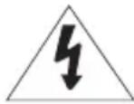
CAUTION
RISK OF ELECTRIC SHOCK. DO NOT OPEN
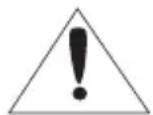
CAUTION:
TO REDUCE THE RISK OF ELECTRIC SHOCK, DO NOT REMOVE COVER (OR BACK) NO USER SERVICEABLE PARTS INSIDE. REFER SERVICING TO QUALIFIED SERVICE PERSONNEL.

This symbol indicates that dangerous voltage consisting a risk of electric shock is present within this unit.

This exclamation point symbol is intended to alert the user to the presence of important operating and maintenance (servicing) instructions in the literature accompanying the appliance
WARNING
To prevent damage which may result in fire or electric shock hazard, do not expose this appliance to rain or moisture.
WARNING
- Be sure to use only the standard adapter that is specified in the specification sheet. Using any other adapter could cause fire, electrical shock, or damage to the product
- Incorrectly connecting the power supply or replacing battery may cause explosion, fire, electric shock, or damage to the product.
- Do not connect multiple cameras to a single adapter. Exceeding the capacity may cause abnormal heat generation or fire.
- Securely plug the power cord into the power receptacle. Insecure connection may cause fire.
- When installing the camera, fasten it securely and firmly. A falling camera may cause personal injury.
- Do not place conductive objects (e.g. screw drivers, coins, metal things, etc.) or containers filled with water on top of the camera. Doing so may cause personal injury due to fire, electric shock, or falling objects.
Safety Information
- Do not install the unit in humid, dusty, or sooty locations.
Doing so may cause fire or electric shock.
- If any unusual smells or smoke come from the unit, stop using the product.
In such case, immediately disconnect the power source and contact the service center.
Continued use in such a condition may cause fire or electric shock.
- If this product fails to operate normally, contact the nearest service center.
Never disassemble or modify this product in any way.
- When cleaning, do not spray water directly onto parts of the product.
Doing so may cause fire or electric shock.
PRECAUTION
Operating
·Before using, make sure power supply and all other parts are properly connected.
- While operating, if any abnormal condition or malfunction is observed, stop using the camera immediately and contact your dealer.
Handling
- Do not disassemble or tamper with parts inside the camera.
- Do not drop the camera or subject it to shock or vibration as this can damage the camera.
- Clean the clear Lens cover with extra care. Scratches and dust can ruin the quality of the camera image.
Installation and Storage
- Do not install the camera in areas of extreme temperature, exceeding the allowed range.
- Avoid installing in humid or dusty environments.
- Avoid installing in places where radiation is present.
- Avoid installing in places where there are strong magnetic ŷelds and electric signals.
- Avoid installing in places where the camera would be subject to strong vibrations.
- Never expose the camera to rain or water.
Important Safety Instructions
- Read these instructions.
- All these safety and operating instructions should be read before the product is installed or operated.
- Keep these instructions.
- The safety, operating and use instructions should be retained for future reference.
- Heed all warnings.
- All warnings on the product and in the operating instructions should be adhered to.
- Follow all instructions.
- All operating and use instructions should be followed.
- Do not use this device near water.
- For example: near a bath tub, wash bowl, kitchen sink, laundry tub, in a wet basement; near a swimming pool; etc.
- Clean only with dry cloth.
- Unplug this product from the wall outlet before cleaning. Do not use liquid cleaners.
- Do not block any ventilation openings. Install in accordance with the manufacturer's instructions.
- Slots and openings in the cabinet are provided for ventilation, to ensure reliable operation of the product, and to protect it from over-heating. The openings should never be blocked by placing the product on bed, sofa, rug or other similar surface. This product should not be placed in a built-in installation such as a bookcase or rack unless proper ventilation is provided and the manufacturer's instructions have been adhere to.
-
Do not install near any heat sources such as radiators, heat registers, or other apparatus (including amplifiers) that produce heat.
-
Do not defeat the safety purpose of the polarized or grounding-type plug. A polarized plug has two blades with one wider than the other. A grounding type plug has two blades and a third grounding prong. The wide blade or the third prong are provided for your safety. If the provided plug does not fit into your outlet, consult an electrician for replacement of the obsolete outlet.
-
Protect the power cord from being walked on or pinched particularly at plugs, convenience receptacles, and the point where they exit from the apparatus.
Important Safety Instructions
- Only use attachments/accessories specified by the manufacturer.
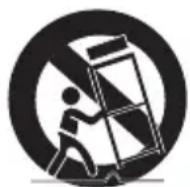
- Use only with cart, stand, tripod, bracket, or table specified by the manufacturer, or sold with the apparatus. When a cart is used, use caution when moving the cart/ apparatus combination to avoid injury from tip-over.
- Unplug this apparatus during lightning storms or when unused for long periods of time.
- Refer all servicing to qualified service personnel. Servicing is required when the apparatus has been damaged in any way, such as power supply cord or plug is damaged, liquid has been spilled or objects have fallen into the apparatus, the apparatus has been exposed to rain or moisture, does not operate normally, or has been dropped.
Disposal of Old Appliances
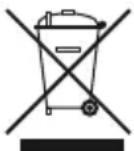
- When this crossed-out wheel bin symbol is attached to a product it means the product is covered by the European Directive 2002/96/EC.
-
All electrical and electronic products should be disposed of separately form the municipal waste stream stream in accordance to laws designated by the government or the local authorities.
-
The correct disposal of your old appliance will help prevent potential negative consequences for the environment and human health.
- For more detailed information about disposal of your old appliance, please contact your city office, waste disposal service or the shop where you purchased the product.
FCC
This equipment has been tested and found to comply with the limits for a Class A digital device, pursuant to part 15 of the FCC Rules.
These limits are designed to provide reasonable protection against harmful interference when the equipment is operated in a commercial environment.
This equipment generates, uses, and can radiate radio frequency energy and, if not installed and used in accordance with the instruction manual, may cause harmful interference to radio communications.
Operation of this equipment in a residential area is likely to cause harmful interference in which case the user will be required to correct the interference at his own expense.
Features
■ Universal HD over Coax™ Technology with HD-Analog, HD-TVI, HD-CVI and all Analog to 960H Signal Support
■ 2.1MP 1/3" Image Sensor at Real-time 30fps
■ HD Analog LPR™ License Plate Recognition Technology captures reflective license
■ plates up to 50mph with a 13'\~30' Capture Range
■ Reliable Performance under Any Lighting Conditions
■ External OSD and Lens Adjustment
■ Varifocal P-Iris Lens 6\~50mm
■ OSD Control Via Coaxial (UTC)
■ 115' Smart IR™ with Intelligent Camera Sync.
■ Smart DNR™ 3D Digital Noise Reduction
■ Highlight Masking Exposure (HME)
■ Auto Sensing 24VAC/12VDC with Line Lock
■ Easy Icon Driven OSD Menu with Built-in Joystick
■ Programmable Privacy Zones
■ Auto Gain Control (AGC)
■ Backlight Compensation (BLC)
■ Dynamic Range Compressor (DRC) Reveals Low Light Detail
■ No Fog or Condensation Under any Weather Conditions
■ IP66 Certified Weather and Tampering Resistant
5 Year Warranty
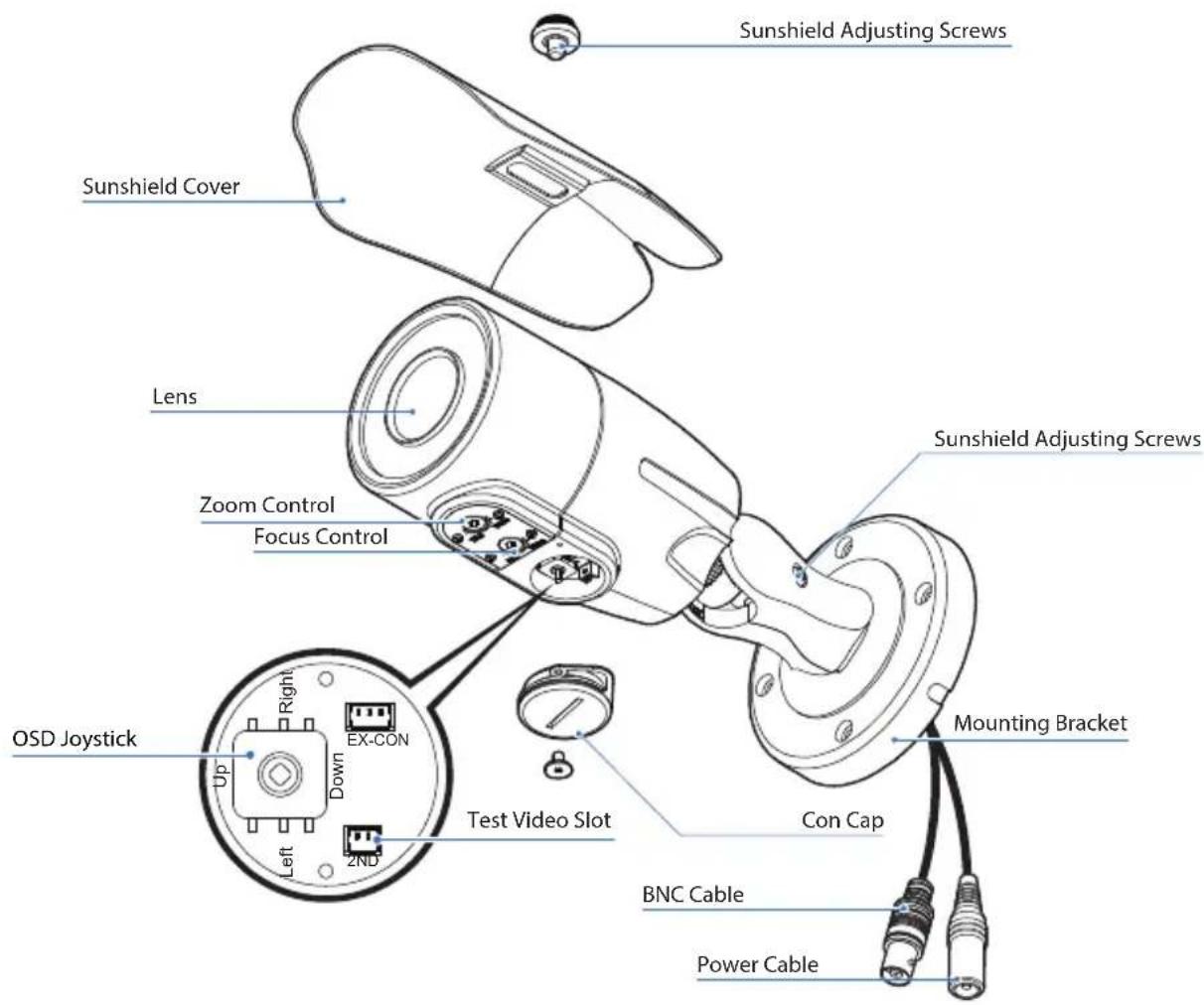
Part name
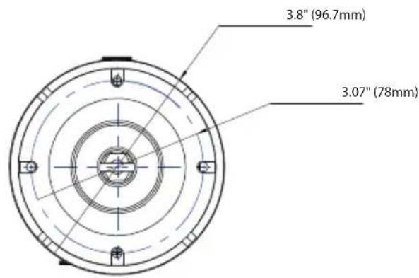
Dimension
Unit: Inches (mm)
Product & Accessories
Please check if all the camera and accessories are included in the package.
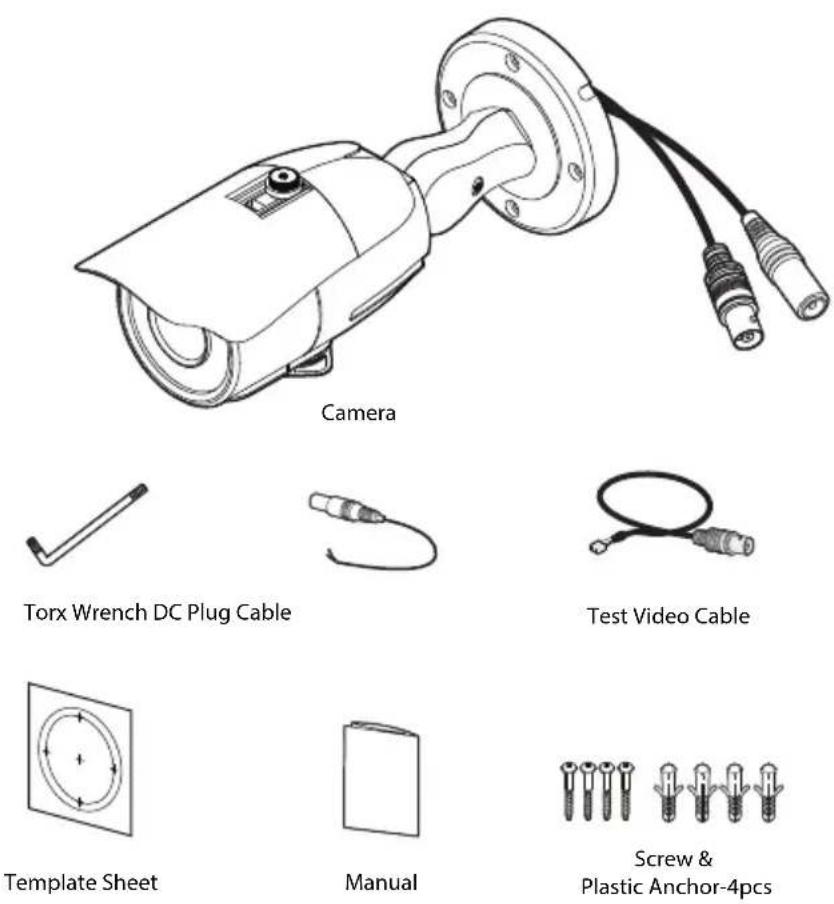
NOTE: The 'Test Video Cable' is used to test the camera by connecting to a portable display.
Installation-Instructions
1 Using the mounting template or your own camera, mark and drill the necessary holes to mount the bracket to a wall or ceiling.
2 Pull a necessary wires through and make the proper connections.
3 Use the four mounting screws to install the camera on the wall or ceiling.
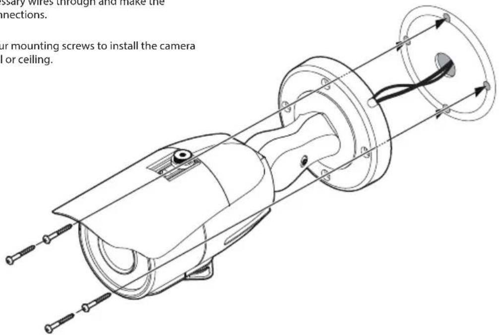
NOTE: Electrical junction box and required screws sold separately.
Installation-Instructions
An LPR camera is designed to read a license plate only. When a license plate passes by the camera, the reflective film on the plate will be reflected back to the camera which gives you the good clear shot of the plate. You will ONLY capture an image of the plate. US license plates need to be at least 216 pixels wide. This translates roughly into an image no wider than 5-6 feet assuming 1080P standard definition video.
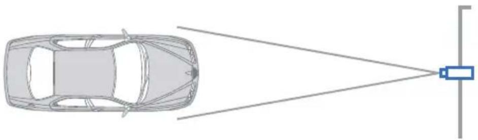
1 The horizontal angle between the camera and plate should be within 20^ degrees. This means that if your camera is 10 feet away from the plate, the plate cannot be more than 3 feet to the right or left of the camera.
2 The vertical angle between the camera and plate is within 30^ degrees. This means that if your camera is 10 feet away from the plate and the plate is 3 feet off the ground, the camera cannot be mounted more than 8 feet high.
3 Attempting to position the security camera at odd angles or exceeding the distance capabilities will result in a poor shot of the plate
4 The DVR's recording fps should be at the highest to assure best capture quality.
natural_image
Top-down diagram of a car with a sensor or detection device emitting light rays from the side, no text or symbols present.THE CAMERA SHOULD BE MOUNTED AT AN ANGLE NO GREATER THAN 30 DEGREES
Installation-Instructions
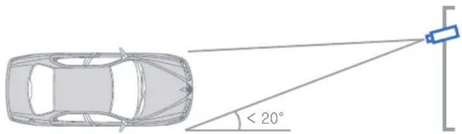
CAMERA ANGLE NO GREATER THAN 20 DEGREES FOR SIDE MOUNT INSTALLATIONS
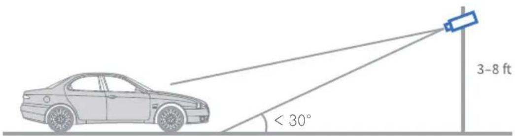
THE CAMERA SHOULD BE MOUNTED AT AN ANGLE NO GREATER THAN 30 DEGREES
Connecting to DVR/Encoder
Use the diagram below to connect to an Universal DVR or CRT Monitor properly.
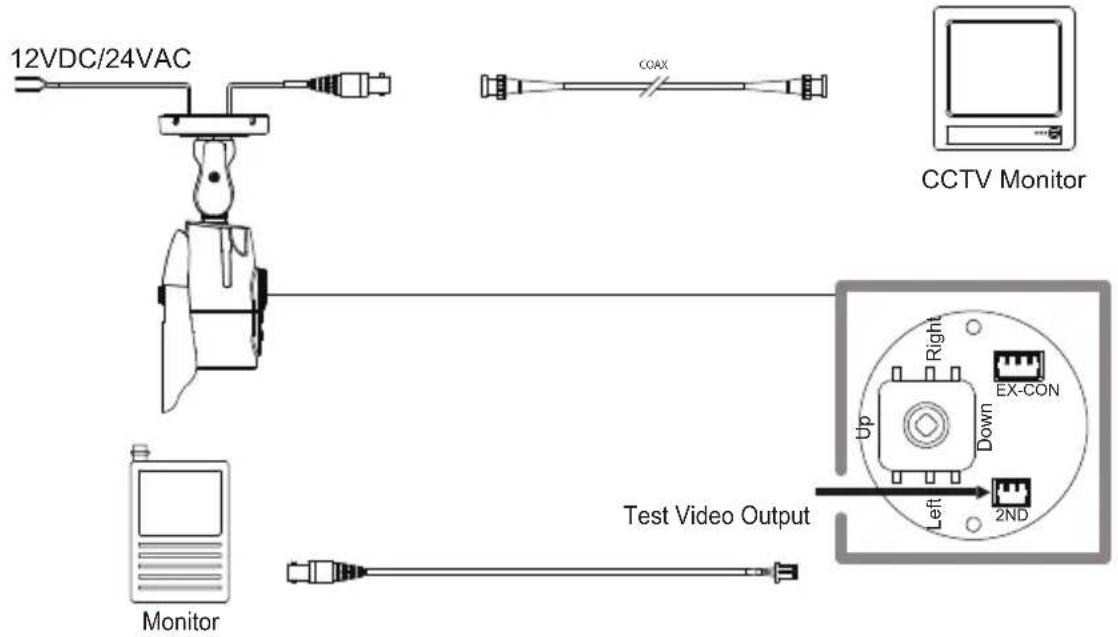
- Power Connection - 12VDC/24VAC Dual Voltage(Auto Polarity Detection and Protection)
- All cameras are equipped with a test video output for on-site configuration.
Control Board
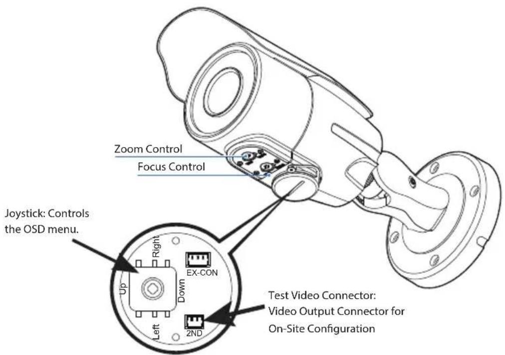
- OSD Joystick: The function setting and video output can be adjusted with OSD joystick. (default: HD-A)
Image Mode
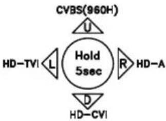
Switches to HD-TVI mode when press OSD Joystick to left 5sec or longer. Switches to HD-A mode when press OSD Joystick to right 5sec or longer. Switches to CVBS mode when press OSD Joystick to up 5sec or longer. Switches to HD-CVI mode when press OSD Joystick to down 5sec or longer.
- Zoom Control : clockwise(Tele), couter-clockwise(Wide)
- Focus Control : clockwise(Far), counter-clockwise(Near)
flowchart
graph TD
    A["CVBS(960H)"] --> B["Hold 5sec"]
    C["HD-TVI"] --> B
    D["HD-A"] --> B
    E["HD-CVI"] --> B
    B --> F["U"]
    B --> G["L"]
    B --> H["R"]
    B --> I["D"]
Adjusting the Camera angle
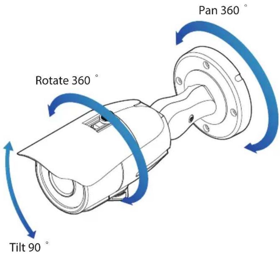
Warning:
- Do not rotate more than 360
- Do not unnecessarily twist too many times.
OSD Menu Tree
NOTE: The function setting can be adjusted with both switch (OSD joystick) and remote control through RS485 or UTC. In case of camera without OSD joystick, it can be adjusted with coaxial (UTC) only.

EXPOSURE
| LENS | MANUAL / AUTO |
| BACKLIGHT | OFF / HME / BLC |
| DRC | OFF / LOW / MIDDLE / HIGH |
| DEFOG | OFF / ON |
| AGC | 0 ~ 10 |
| 3D DNR | OFF / LOW / MIDDLE / HIGH |
| EXIT JUMP |

COLOR (not used)
| EXIT JUMP |

DAY & NIGHT
| SMART IR | 0 ~ 20 |
| EXIT JUMP |

FUNCTION
| SHARPNESS | 0 ~ 10 |
| GAMMA | 0.45 ~ 0.75 |
| MIRROR | OFF / ON |
| FLIP | OFF / ON |
| EXIT JUMP |

MOTION
| MOTION | OFF / ON |
| DET WINDOW | |
| DET TONE | 0 ~ 4 |
| MDRECT FILL | OFF / ON |
| SENSITIVITY | 0 ~ 10 |
| MOTION OSD | OFF / ON |
| TEXT ALARM | OFF / ON |
| SIGNAL OUT | OFF / ON |
| EXIT JUMP | |

PRIVACY
| PRIVACY | OFF / ON |
| ZONE NUM | 0 ~ 15 |
| ZONE DISP | OFF / ON |
| H-POS | 0 ~ 59 |
| V-POS | 0 ~ 33 |
| H-SIZE | 0 ~ 60 |
| V-SIZE | 0 ~ 34 |
| Y LEVEL | 0 ~ 20 |
| CB LEVEL | 0 ~ 20 |
| CR LEVEL | 0 ~ 20 |
| TRANS | 0 ~ 3 |
| EXIT JUMP |

SETUP
| COMMUNICA | |
| CAM TITLE | OFF / RIGHT UP / LEFT DOWN |
| IMAGE RANGE | FULL / COMP / USER |
| FREQ | 50Hz / 60Hz |
| LANGUAGE | ENG/ CHN/ CHN(S)/ JPN / KOR |
| INITIAL | OFF / ON |
| EXIT JUMP | |

EXIT
| SAVE & EXIT |
| EXIT |
This is a License Plate Recognition Camera. As such, it has been programmed specifically to register licese plates only. For optimal results, this camera is set to B/W mode only. Thers is Color mode on this camera. As a result, some of the menu options, such as Color and Day/Night menu options, are disabled for this camera.
OSD Menu\_Exposure
1 LENS
MANUAL: Manual mode supports the fixed board lens or the manual iris lens. AUTO: AUTO mode sets the camera's iris automatically.
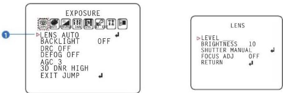
Under the LENS sub-menu, you can adjust the following settings:
1. Level
Change the camera's iris value manually. If AUTO is selected, this option is disabled.
2. Brightness
Adjust the camera's brightness from 0\~20. The higher the number, the brighter the image will appear.
3. Shutter
Set the shutter speed to AUTO, Manual, or FLC (Flicker-less mode).
* If AUTO is selected, select from the following options :
- NORMAL: Set when the camera is installed in an indoor environment.
- DEBLUR: Set when the camera is installed in an outdoor environment.
* Select FLC if the camera is experiencing some flickering in the image.
The shutter speed will be set to 1/100 for NTSC, or 1/120 for PAL.
* If Manual is selected, set the shutter speed from the options :
- 1/30(1/25) \~ 1/30000. (Default: Manual 1/1000)
4. Focus Adjustment
When on, the default level is set automatically by controlling lens focus and based on the installation and environment circumstances.
OSD Menu\_Exposure

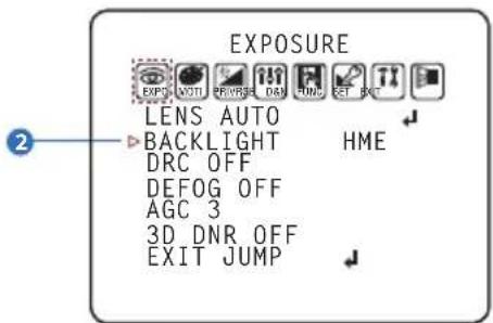
BACKLIGHT
OFF
HME HIGHLIGHT MASKING EXPOSURE
HME allows objects to appear clearly on the screen by masking extremely bright areas. To setup HME, set the level and color. The lower the setting, the darker the masking areas have to be. Select from: 0 \~ 20.
Color: Set the color of the HME mask. Select from:
BLACK/WHITE/YELLOW/CYAN/GREEN/
MAGENTA / RED / BLUE / CUSTOMIZE
BLC BACK LIGHT COMPENSATION
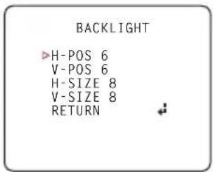
If BLC is selected, adjust the size and position of the mask:
- H-POS: Move the Zone position left or right. The higher the number, the zone will move to the right.
- V-POS: Move the Zone position up or down. The higher the number, the zone will move down.
- H-Size: Reset the zone's size horizontally. The higher the number, the right side panel will move further to the right.
- V-Size: Reset the zone's size vertically. The higher the number, the bottom side panel will move further down.
OSD Menu Exposure
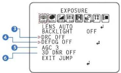
3 DRC (DYNAMIC RANGE COMPRESSOR)
DRC enables dark areas in images to become more visible without overexposing the bright areas to create one perfect image. Select from : OFF / LOW / MIDDLE / HIGH
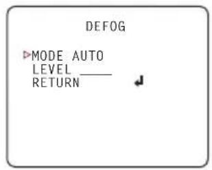
4 DEFOG
Allows the camera to process a scene that is obscured by fog or weather conditions and provides a visibly improved image. AUTO / Manual : Select AUTO to have the WDR and DRC levels adjusted automatically. Set the DEFOG level from LOW / MIDDLE / HIGH.
5 AGC (AUTO GAIN CONTROL)
0\~10 - AGC enhances the picture brightness in low light conditions. A higher level AGC setting makes the images brighter, however, it could increase the amount of noise.
6 3D DNR (3D DIGITAL NOISE REDUCTION)
OFF/LOW/MIDDLE/HIGH - 3D-DNR reduces the noise on the screen in low light conditions and allows for clearer images, even at night.
OSD Menu\_Color
NOT USED
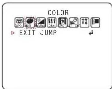
This is a License Plate Recognition Camera. As such, it has been programmed specifically to register license plates only. For optimal results, this camera is set to B/W mode only. There is no Color mode on this camera. As a result, White Balance and Color Gain under the Color Menu and Day/Night Mode, Control and Delay options under the Day/Night Menu are not used for this camera.
OSD Menu\_Day & Night
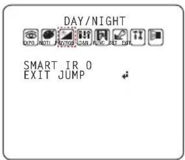
1 SMART IR
0 \~ 20 : Enable Smart IR and set the level. Higher values will make Smart IR stronger.
OSD Menu\_Function
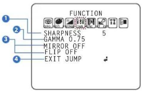
1 SHARPNESS
0 \~ 10 - Sets the image sharpness. The higher the number, the sharper the image.
2 GAMMA
0.45 \~ 0.75 - Select the desired gamma level. 0.75 is default setting.
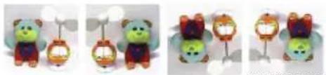
3 MIRROR / FLIP
OFF
MIRROR : Reflects the camera horizontally.
FLIP : Reflects the camera vertically.
natural_image
Three identical cartoon bear figurines with colorful accessories, displayed side by side (no text or symbols visible)Mirror & Flip ONFlip ONMirror ONMirror / Flip OFF
OSD Menu\_Motion
The camera can detect movement and display an alarm on the screen. when movement is detected.
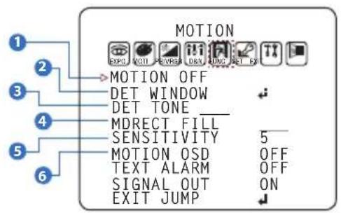
1 MOTION
To use the motion detection settings, be fore Motion is ON.
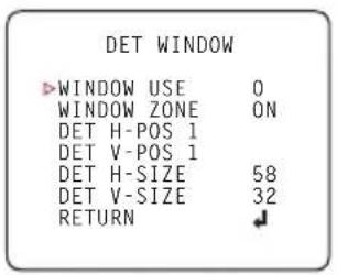
2 DET WINDOW
MOTION ZONE setting
3 DET TONE
Four each different motion tone color available
4 MDRECT FILL
Color setting for operating motion zone
5 SENSITIVITY
The smaller the movement you want to detect, the higher the sensitivity value must be.
6 MOTION OSD
MOTION OSD interoperable with 'DET TONE' and 'MDRECT FILL'.
7 TEXT ALARM
Setup a text to appear on the screen when motion is detected explaining the alarm situation.
- WINDOW MOTION: Will appear when a motion alarm is detected.
- CAMERA MOVING : Will appear if the camera is shaken abruptly.
8 SIGNAL OUT (ON / OFF)
- ON : 'HIGH' SIGNAL OUT upon ALARM.
- OFF : 'SIGNAL OUT' off regardless of ALARM
OSD Menu\_Privacy
You can hide some parts of the screen for privacy masking. A total of 16 different privacy masking zones are available. The cameras support square privacy masks or advanced polygon masks.
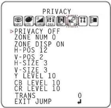
- ZONE NUM : Select the zone number between 0\~15.
- ZONE DISP : Zone display ON/OFF
- H-POS : Move the Zone position Left or right. The higher the number, the zone will move to the right.
- V-POS : Move the Zone position up or down. The higher the number, the zone will move down.
- H-SIZE : Reset the zone's size horizontally. The higher the number, the right side panel will move further to the right.
- V-SIZE : Reset the zone's size vertically. The higher the number, the bottom side panel will move further down.
- Y LEVEL : The higher the number, the brighter the color will appear.
- CR LEVEL : The higher the number, the more red tone will be added to the zone's color.
The lower the number, the more green will be added to the zone's color. - CB LEVEL: The higher the number, the more red tone will be added to the zone's color.
The lower the number, the more red will be added to the zone's color.
* High CB Level + High CR Level = Pink
* High CB Level + Low CR Level = Sky Blue
* Low CB Level + High CR Level = Orange - TRANS : Set the mask's transparency level from 0\~3. The default value is 0.
OSD Menu\_Setup
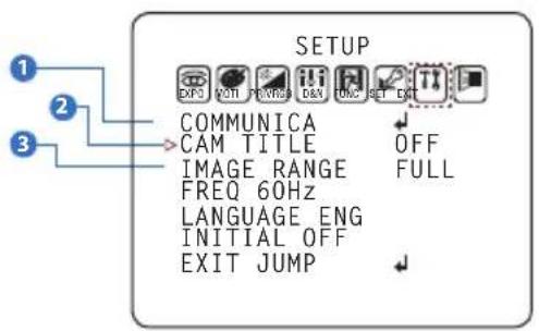
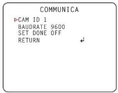
1 COMMUNICATION
Adjust the camera's ID and Baudrate. Default Protocol is Pelco-D.
- CAM ID : Provide an ID number for the camera (0 \~ 255).
- BAUDRATE : 9600bps is default. Select the baudrate from the following options : 2400/4800/9600/57600/115200 bps.
- SET DONE : Set the value of CAM ID and BAUDRATE.
NOTE: Be sure to press "Save&Exit" button on the EXIT menu before saving.
2 CAM. TITLE
Add a name to the camera. Set the title by using the OSD joystick.
3 IMAGE RANGE
Image Range allows you to set the proper Black and White levels according to the external display you use.
- FULL : Display all BLACK level and WHITE level without compression.
- COMP : Display BLACK level and WHITE level with compression.
- USER : Reset the BLACK level by changing the OFFSET value.
OSD Menu\_Setup
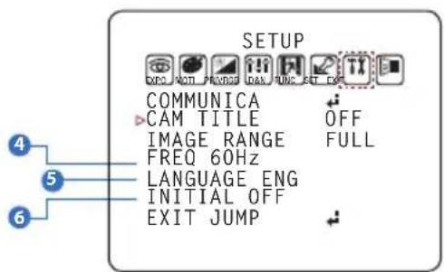
4 FREQ
When the camera's image appears to have flickering issues, change the frequency value to adjust the image.
5 LANGUAGE
Select from the following: English (Default), Chinese, Chinese (S), Japanese, and Koran.
6 INITIAL
Reset the camera to its default settings. Press and hold the select button for five (5) seconds.
OSD Menu\_EXIT
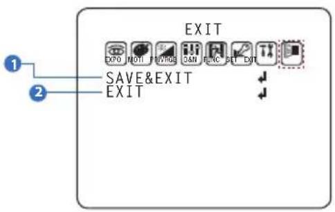
1 SAVE & EXIT
Exit the OSD menu after saving the recent changes.
2 EXIT
Exit the OSD menu without saving any changes.
Troubleshooting
Before sending your camera for repair, check the following or contact our technical specialist.
FOR NO VIDEO
Check the coaxial cable and make sure it is connected securely.
Check the power supply and make sure the camera has the proper voltage and current.
FOR OUT-OF-FOCUS VIDEO
Check the Front case cover and the lens for dirt or fingerprints. Use a soft cloth and gently clean.
The use of a field test monitor is recommended.
Specifications
| VIDEO | |
| Image Sensor 1/3" CMOS Sensors | |
| Active Pixels 1944(H) x 1092(V) | |
| Scanning System Progressive scan | |
| Freguency | 60Hz / 50Hz |
| Signal Technology | 2.0 Megapixel Universal |
| Synchronization | Internal |
| Resolution | 1920x1080 (1080p30fps) |
| Minimum Scene Illumination | F1.6 (30IRE): 0 Lux (B&W) |
| S/N Ratio 55dB | |
| Video Output | BNC (Universal : HD-A/HD-TVI/HD-CVI/CVBS) |
| LENS | |
| Focal Length & Lens Type | 6~50mm, P-Iris Vari-Focal |
| IR Distance | 115ft |
| OPERATIONAL | |
| Shutter Speed 1/30(25) - 1/30,000 | |
| Backlight OFF/HME/BLC | |
Specifications
| OPERATIONAL (CONT.) | |
| Digital Noise Reduction OFF / LOW / MIDDLE / HIGH | |
| Day and Night NIGHT | |
| 0 ~ 10Auto Gain Control | |
| ON/OFF (4 Zones)Motion Detection | |
| Privacy Zones | ON/OFF (16 Zones) |
| Sharpness | 0 ~ 10 |
| Gamma | 0.45 ~ 0.75 |
| Remote Control | Coaxial (UTC) |
| ENVIRONMENTAL | |
| Operating Temperature | -4°F ~ 122°F (-20°C ~ 50°C) |
| Operating Humidity | No more than 90% (Non-Condensing) |
| IP Rating | IP66 |
| Other Certifications FCC, CE, ROHS | |
| ELECTRICAL | |
| Power Requirements DC12V / AC24V Dual Voltage | |
| Power Consumption DC12V : 6.12W, 510mA | |
| MECHANICAL | |
| Housing Material and Dimensions | Aluminum, 10.4 x 3.81 in (264 x 96.7mm) |
| Weight 1.79 lbs | |
Limits & Exclusions
There are no express warranties except as listed. The warranter will not be liable for incidental or consequential damages (including damage to recording media without limitation) resulting from the use of these products or arising out of any breach of the warranty. All express and implied warranties, including the warranties of merchantability and fitness for particular purpose, are limited to the applicable warranty period set forth above.
Some states do not allow the exclusion or limitation of incidental or consequential damages, or limitations on how long an implied warranty lasts, so the exclusions or limitations listed above may not apply to you. This warranty gives you specific legal rights, and you may also have other rights that vary from state-to-state.
If the problem is not handled to your satisfaction, then write to the following address:
Digital Watchdog, Inc.
ATTN: RMA Department
5436 W. Crenshaw Street
Tampa, FL 33634
Service calls which do not involve defective materials or workmanship as determined by the Warranter, in its sole discretion, are not covered. Costs of such service calls are the responsibility of the purchaser.
Warranty Information
Digital Watchdog (referred to as “the Warranter”) warrants the Digital Watchdog Camera against defects in materials or workmanship as follows:
LABOR: For the initial five (5) years and one (1) year on IR LED from the original purchase date, if the camera is determined to be defective, the Warranter will repair or replace the unit with a new or refurbished product at its option at no charge.
PARTS: In addition, the Warranter will supply replacement parts for the initial five (5) years and one (1) year on IR LED.
To obtain warranty or out of warranty service, please contacta Technical Support Representative at 1+ (866)446-3595 Monday through Friday from 9:00AM to 8:00PM Eastern Standard Time.
A purchase receipt or other proof of the original purchase date is required before warranty service is rendered. This warranty only covers failures due to defects in materials and workmanship which arise during normal use. This warranty does not cover damage which occurs in shipment or failures which are caused by products not supplied by the Warranter or failures which result from accident, misuse, abuse, neglect, mishandling, misapplication, alteration, modification, faulty installation, set-up adjustments, improper antenna, inadequate signal pickup, maladjustment of consumer controls, improper operation, power line surge, improper voltage supply, lightning damage, rental use of the product or service by anyone other than an authorized repair facility or damage that is attributable to acts of God.
Notes
Notes
DW
DIGITAL
WATCHDOG™
Complete Surveillance Solutions
East Coast Headquarters Office: 5436 W Crenshaw St, Tampa, FL 33634 West Coast Headquarters Office: 16220 Bloomfield Ave., Cerritos, CA 90703
PH: 866-446-35951 FAX: 813-888-9262
www.Digital-Watchdog.com Technical Support:
USA & Canada 1+ (866) 446-3595
International 1+ (813) 888-9555
French Canadian 1+ (514) 360-1309
Support Hours: Monday-Friday 9:00am to 8:00pm EST
- STAR-LIGHT Universal HD over Coax™ License Plate Recognition Bullet Camera
- Index
- INTRODUCTION
- INSTALLION
- OSD MENU
- APPENDIX
- Safety Information
- CAUTION
- CAUTION:
- WARNING
- PRECAUTION
- Operating
- Handling
- Installation and Storage
- Important Safety Instructions
- Disposal of Old Appliances
- FCC
- Features
- Part name
- Dimension
- Product & Accessories
- Installation-Instructions
- Connecting to DVR/Encoder
- Control Board
- Image Mode
- Adjusting the Camera angle
- Warning:
- OSD Menu Tree
- OSD Menu\_Exposure
- LENS
- Level
- Brightness
- Shutter
- Focus Adjustment
- BACKLIGHT
- OFF
- HME HIGHLIGHT MASKING EXPOSURE
- BLC BACK LIGHT COMPENSATION
- OSD Menu Exposure
- DRC (DYNAMIC RANGE COMPRESSOR)
- DEFOG
- AGC (AUTO GAIN CONTROL)
- 3D DNR (3D DIGITAL NOISE REDUCTION)
- OSD Menu\_Color
- OSD Menu\_Day & Night
- SMART IR
- OSD Menu\_Function
- SHARPNESS
- GAMMA
- MIRROR / FLIP
- OSD Menu\_Motion
- OSD Menu\_Privacy
- OSD Menu\_Setup
- COMMUNICATION
- CAM. TITLE
- IMAGE RANGE
- FREQ
- LANGUAGE
- INITIAL
- OSD Menu\_EXIT
- SAVE & EXIT
- EXIT
- Troubleshooting
- FOR NO VIDEO
- FOR OUT-OF-FOCUS VIDEO
- Specifications
- Limits & Exclusions
- Warranty Information
- Notes
- DW
- DIGITAL
- WATCHDOG™
- Complete Surveillance Solutions
Brand : Digital Watchdog
Model : DW LPR DWC-LPR650U
Category : Security Camera