Star-Light DWC-PTZ37XFM - Security Camera Digital Watchdog - Free user manual and instructions
Find the device manual for free Star-Light DWC-PTZ37XFM Digital Watchdog in PDF.


| Product Type | Security Camera |
| Model | Star-Light DWC-PTZ37XFM |
| Brand | Digital Watchdog |
| Category | Super Speed Dome PTZ Camera |
| Dimensions (Ceiling Hole) | 190 mm diameter |
| Weight | 12.8 lbs (5.8 kg) |
| Power Supply | AC 24V, 24W (heater off) / 57W (heater on) |
| Image Sensor | 1/4" Interline Transfer CCD |
| Effective Pixels | 768 (H) x 494 (V), 380K |
| Horizontal Resolution | Color: 560 TV lines, B/W: 680 TV lines |
| Zoom | 37x optical + 16x digital (total 592x) |
| Focal Length | 3.5 mm (W) ~ 129.5 mm (T), F1.6 ~ F3.9 |
| Angle of View | H: 55.5° (W) ~ 1.59° (T), V: 42.5° (W) ~ 1.19° (T) |
| Minimum Illumination | Color: 0.7 Lux (F1.6, 50IRE), B/W: 0.07 Lux (F1.6, 50IRE) |
| Pan/Tilt Range | Pan: 360° endless, Tilt: 0° ~ 180° (auto-flip on) or 0° ~ 90° (off) |
| Presets | 127 presets with labels, independent camera setup |
| Patterns | 4 patterns |
| Scans | 8 scans |
| Groups | 8 groups (max 20 entries per group) |
| Privacy Zones | 8 zones |
| Alarm I/O | 8 inputs, 4 relay outputs |
| Communication Protocol | Auto, Pelco-D/P, Samsung, Panasonic, GE (Kalatel), AD |
| OSD Languages | 7 languages (English, Spanish, French, German, Italian, Russian, Portuguese) |
| Operating Temperature | -10°C to 50°C (14°F to 122°F) |
Frequently Asked Questions - Star-Light DWC-PTZ37XFM Digital Watchdog
User questions about Star-Light DWC-PTZ37XFM Digital Watchdog
0 question about this device. Answer the ones you know or ask your own.
Ask a new question about this device
Download the instructions for your Security Camera in PDF format for free! Find your manual Star-Light DWC-PTZ37XFM - Digital Watchdog and take your electronic device back in hand. On this page are published all the documents necessary for the use of your device. Star-Light DWC-PTZ37XFM by Digital Watchdog.
USER MANUAL Star-Light DWC-PTZ37XFM Digital Watchdog
natural_image
Technical line drawing of a mechanical component with no visible text or symbolsSuper Speed Dome
PTZ37XFM PTZ37X In-Ceiling Flush Mount
User's Manual
Before installing and using the camera, please read this manual carefully. Be sure to keep it handy for future reference.
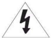
CAUTION
RISK OF ELECTRIC SHOCK. DO NOT OPEN.
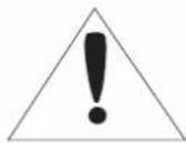
CAUTION:
TO REDUCE THE RISK OF ELECTRIC SHOCK, DO NOT REMOVE COVER (BACK). THERE ARE NO USER SERVICABLE PARTS INSIDE. REFER SERVICING TO QUALIFIED SERVICE PERSONNEL.
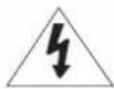
WarningPrecaution
This symbol indicates that dangerous voltage consisting a risk of electric shock is present within this unit.
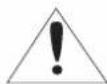
This exclamation point symbol is intended to alert the user to the presence of important operating and maintenance (servicing) instructions in the literature accompanying the appliance.
WARNING
To prevent damage which may result in fire or electric shock hazard, do not expose this appliance to rain or moisture.
WARNING
- Be sure to use only the standard adapter that is specified in the specification sheet. Using any other adapter could cause fire, electrical shock, or damage to the product.
- Incorrectly connecting the power supply or replacing battery may cause explosion, fire, electric shock, or damage to the product.
- Do not connect multiple cameras to a single adapter. Exceeding the capacity may cause abnormal heat generation or fire.
- Securely plug the power cord into the power receptacle. Insecure connection may cause fire.
When installing the camera, fasten it securely and firmly. A falling camera may cause personal injury. - Do not place conductive objects (e.g. screw drivers, coins, metal objects) or containers filled with water on top of the camera. Doing so may cause personal injury due to fire, electric shock, or falling objects.
- Do not install the unit in humid, dusty, or sooty locations. Doing so may cause fire or electric shock.
- If any unusual smells or smoke come from the unit, stop using the product. In such case, immediately disconnect the power sorce and contact the service center. Continued use in such a condition may cause fire or electric shock.
- If this product fails to operate normally, contact the nearest service center. Never disassemble or modify this product in any way.
- When cleaning, do not spray water directly onto parts of the product. Doing so may cause fire or electric shock.
Safety Information
PRECAUTION
Operating
• Before using, make sure power supply and others are properly connected.
- While operating, if any abnormal condition or malfunction is observed, stop using the camera immediately and then contact your Special dealer.
Handling
- Do not disassemble or tamper with parts inside the camera.
- Do not drop or subject the camera to shock and vibration as this can damage the camera.
- Care must be taken when you clean the clear dome cover. Scratch and dust will ruin the quality of the camera.
Installation and Storage
- Do not install the camera in areas of extreme temperature, which exceed the allowable range.
- Avoid installing in humid or dusty places.
- Avoid installing in places where radiation is present.
- Avoid installing in places where there are strong magnetic fields and electric signals.
- Avoid installing in places where the camera would be subject to strong vibrations.
-
Never expose the camera to rain or water.
-
Read these instructions.
- Keep these instructions for future reference.
- Heed all warnings.
-
Follow all instructions.
-
Do not use this camera near water.
-
Clean only with a dry cloth. Unplug the camera from the wall outlet before cleaning.
-
Do not block any ventilation openings to ensure reliable operation of the product ad to protect it from over-heating. Install in accordance with the manufacturer's instructions.
-
Do not install the camera near any heat sources such as radiators, heat registers, or other apparatus that produce heat.
-
Do not defeat the safety purpose of the polarized or grounding-type plug. A polarized plug has two blades with one wider than the other. A grounding type plug has two blades and a third grounding prong. The wide blade or the third prong are provided for your safety. If the provided plug does not fit into your outlet, consult an electrician for a replacement.
-
Protect the power cord from being walked on or pinched particularly at or near plugs, convenience receptacles, and the point where they exit from the apparatus.
-
Only use attachments/accessories specified by the manufacturer.
-
Use only with cart, stand, tripod, bracket, or table specified by the manufacturer or sold with the apparatus. Unplug this camera when a cart is used. Use caution when moving the cart that contains the camera to avoid injuries that can result from the camera falling over.

natural_image
Symbolic icon of a person pushing a ladder inside a circle (no text or symbols)-
Unplug the camera during lightning storms or when it is not being used for long periods of time.
-
Refer all servicing to qualified service personnel. Servicing is required when the apparatus has been damaged in any way, such as power supply cord or plug is damaged, liquid has been spilled on the camera, objects have fallen into the camera, the camera has been exposed to rain or moisture, the camera does not operate normally, or the camera has dropped.
-
Introduction | 6 Product & Accessories
7 Part Name -
Installation | 8 DIP Switch Setup
10 Installation
14 Cabling -
OSD | 16 Check Points Before Operation
17 Functions
18 OSD Display of Main Screen
19 General Rules of Menu Operation
20 ROOT MENU > SYSTEM INFORMATION
21 DISPLAY SETUP > CAMERA ID
22 DISPLAY SETUP > PRIVACY ZONE
24 MOTION SETUP
26 FUNCTION SETUP > PRESET SETUP
28 FUNCTION SETUP > SCAN SETUP
29 FUNCTION SETUP > PATTERN SETUP
30 FUNCTION SETUP > GROUP SETUP
32 FUNCTION SETUP > SCHEDULE SETUP
34 CAMERA SETUP > WB SETUP
36 CAMERA SETUP > AE SETUP
38 CAMERA SETUP > SPECIAL
39 SYSTEM SETUP
41 SYSTEM INITIALIZE -
Specifications | 42 Dimension
43 Specification PTZ37XFM
1 Introduction - Product & Accessories
ProductAccessories

natural_image
Simple line drawing of a hat with a circular rim and concentric rings (no text or symbols)Dome Cover
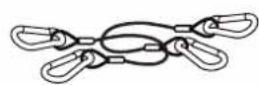
Safety Wire X2

CD with User's Manual
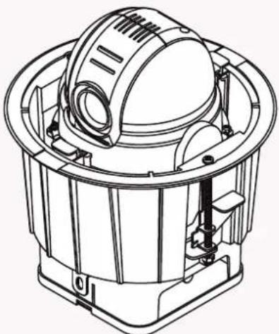
natural_image
Technical line drawing of a mechanical device with internal components (no text or symbols)In-Ceiling Housing with PTZ Mechanism

Quick Start Guide
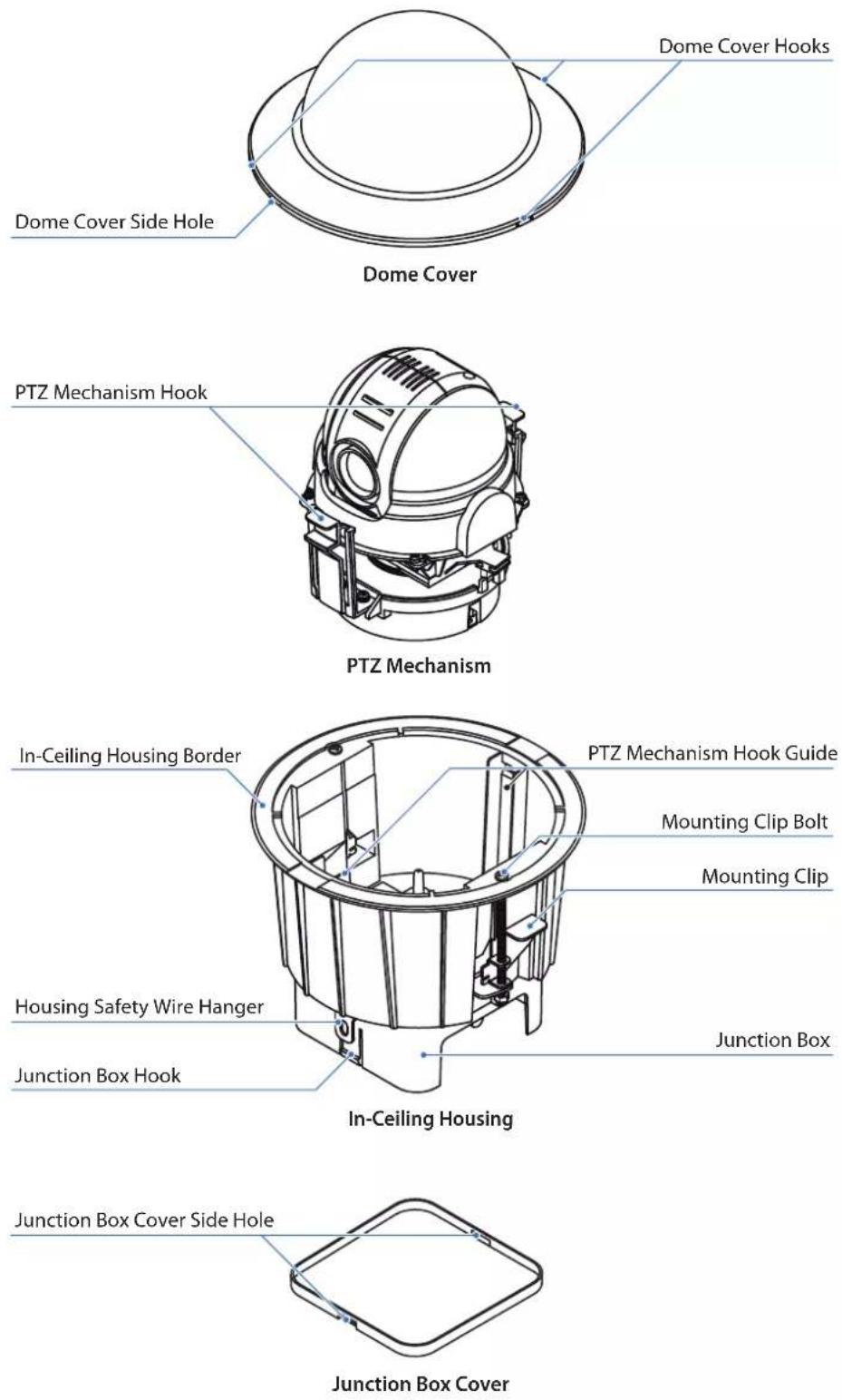
2 Installation - DIP Switch Setup
Before installing the camera, you should set the DIP switch to configure the camera ID (Communication Protocol).
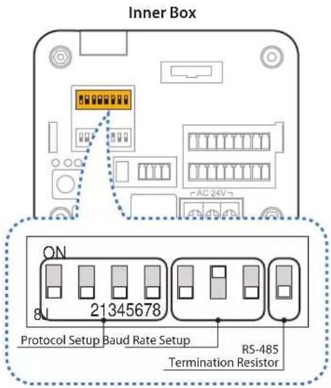
1. Communication Protocol Setup
Configure the appropriate protocol with DIP switch using the DIP switch combination.
1 AUTO - Factory Default
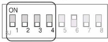
2 PELCO-D
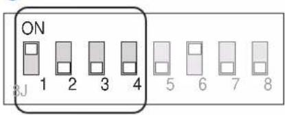
3 PELCO-P
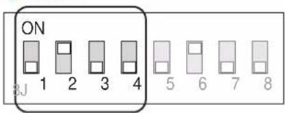
4 SAMSUNG
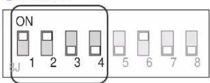
5 PANASONIC
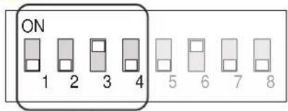
6 GE (Kalatel)
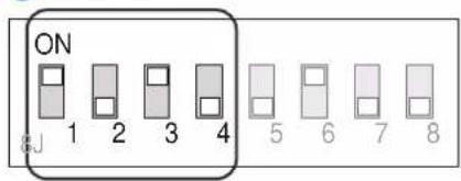
7 AD (American Dynamics)
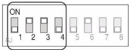
- If you set the protocol as AUTO protocol, camera will automatically recognize the type of protocol being used; however, this will not recognize the AD protocol.
- If you want to control the camera using the DVR or system keyboard, the protocol must be identical to the camera protocol. Otherwise, you will not bwe able to control the camera.
- If you change the camera protocol by adjusting the DIP switch, the change will be effective after you reboot the camera.
2 Installation - DIP Switch Setup
2. Communication Baud Rate Setup
Select the appropriate baud rate with DIP switch combination.
1 2400 BPS - Factory Default
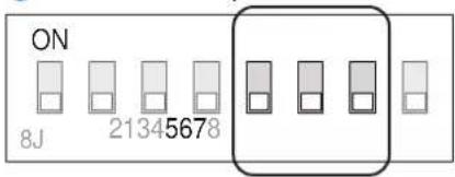
2 4800 BPS
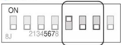
3 9600 BPS
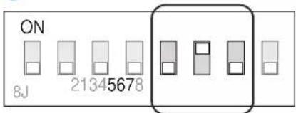
4 19200 BPS
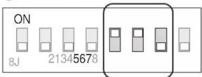
5 38400 BPS
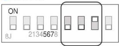
3. RS-485 Termination Resistor
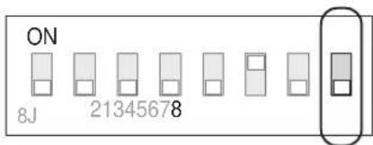
- Pin 8 is used to control RS-485 termination.
- Normally, it must be set to OFF state.
- When you have trouble with long daisy chain style connection, turn ON this termination switch for the last camera.
4. Camera ID Setup
Inner Box
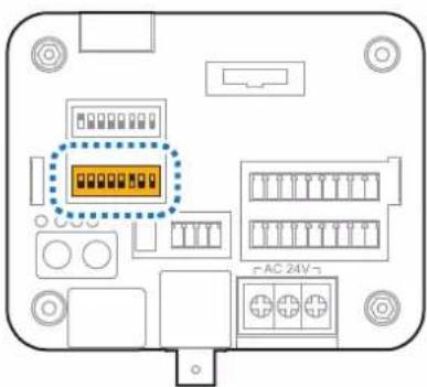
ID number of camera is set using binary number. The example is shown below.
- If you want to control the camera with another device, you must match the Camera ID with CAM ID, setting on DVR or thekeyboard controller.
- ID number of the camera is set using binary number.
- The range of ID is 0\~255.
- Factory default of camera ID is 1.
- Camera ID will be effective without rebooting the camera.
2 Installation - Installation
natural_image
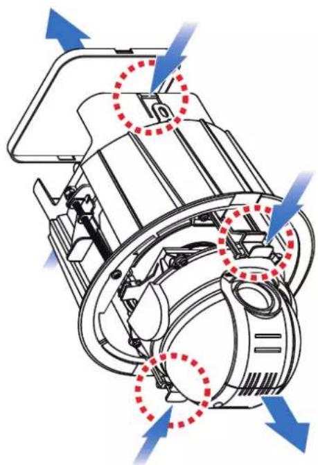
Technical diagram of a mechanical device with blue arrows indicating flow direction (no text or symbols)1 DETACH PTZ MECHANISM AND JUNCTION BOX COVER By pressing down and holding up the hooks located on both sides of the PTZ Mechanism, detach PTZ Mechanism from the housing. Then, detach the junction box cover by pressing down the hooks on both sides of the junction box.
natural_image
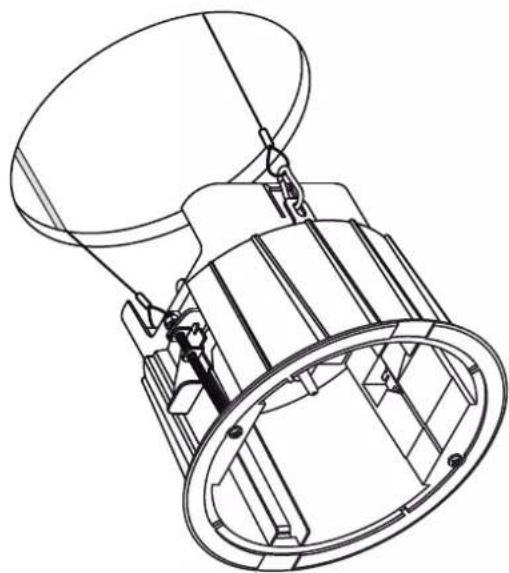
Technical line drawing of a mechanical device with no visible text or symbols2 DRILL THE HOLE ON THE CEILING To install the in-ceiling housing in the ceiling, first drill a 190mm diameter hole on the ceiling.
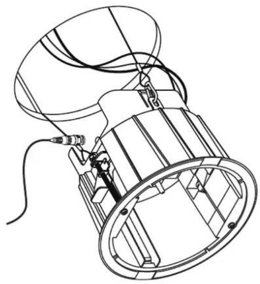
3 HOOK THE SAFETY WIRES Connect one of the rings for the safety wire with the housing safety wire hanger to prevent the junction box cover from falling down. Then, connect the other ring with the hanger bolt of the ceiling.
2 Installation - Installation
natural_image
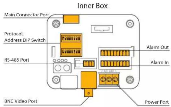
Technical line drawing of a mechanical device with hoses and components (no text or symbols)4 CONNECT THE WIRES AND TERMINAL BLOCKS
Connect the cables to terminal blocks and BNC located in the inner box of the junction box.
See "Installation - Cabling" in the next section.
natural_image
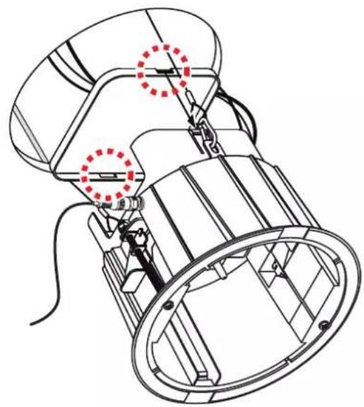
Technical line drawing of a mechanical device with no visible text or symbols5 CLOSE THE JUNCTION BOX COVER
Close the junction box cover by attaching the junction box hooks to the side holes on the junction box cover.
2 Installation - Installation
natural_image
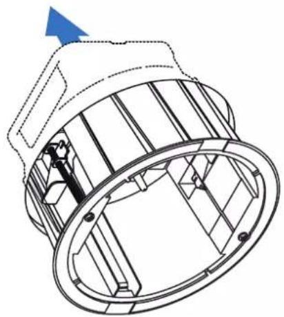
Technical line drawing of a mechanical component with internal structure and directional arrow (no text or symbols)6 INSERT THE IN-CEILING HOUSING
Insert the housing into the ceiling hole and press the edge of the housing against the ceiling.
natural_image
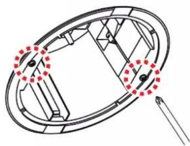
Pure mechanical diagram showing a circular component with internal components and red dotted arrows indicating motion or force directions (no text or symbols)7 INSERT THE IN-CEILING HOUSING
Fix the in-ceiling housing by turning the clip bolts located on the housing clockwise.
natural_image
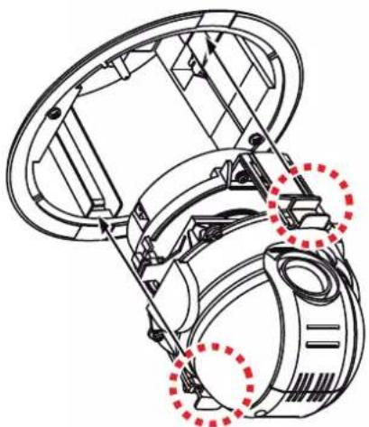
Technical line drawing of a mechanical assembly with red dashed circles highlighting specific components (no text or symbols present)8 INSERT THE PTZ MECHANISM
Insert the PTZ mechanism into the upper housing by aligning the hooks of the PTZ mechanism to the hook guides located on the housing.
2 Installation - Installation
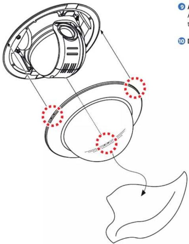
9 ATTACH THE DOME COVER
Attach the dome cover by fixing the dome cover side hooks to the edge of the housing.
10 DETACH THE PROTECTION VINYL
natural_image
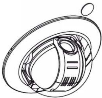
Technical line drawing of a mechanical component with concentric rings and a central shaft (no text or symbols)DETACH THE DOME COVER
Detach the dome cover from the cover side hole by using a flathead screwdriver or a coin.
2 Installation - Cabling
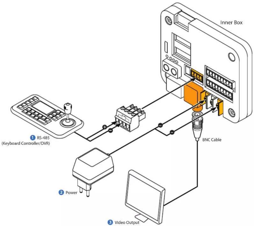
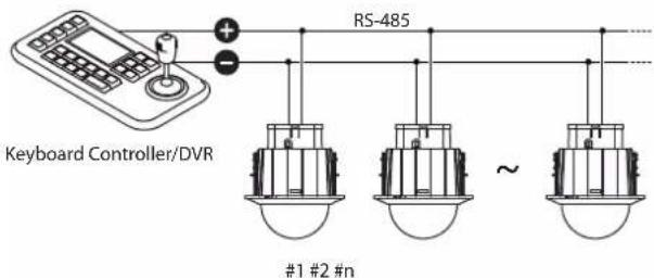
① RS-485 Communication (DVR/Keyboard)
For PTZ control, connect this line to keyboard and DVR. To control multiple cameras at the same time, the RS-485 communication lines should be connected in parallel as shown below.
2 Power Connection
Please check the voltage and the current capacity of rated power carefully.
| Rate Power | Current Consumption |
| AC 24V | Heater OFF: 24W, 1000mA | Heater ON: 57W, 2400mA |
3 Video Output
Connect with BNC coaxial cable.
2 Installation - Cabling
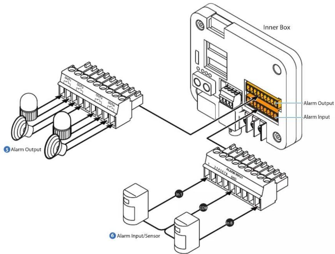
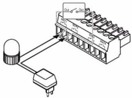
5 Alarm Output
There are 4 alarm outputs, and they are the relay contact type. Therefore, you do not have to worry about the polarity, AC or DC, and the isolations between channels. However, care must be taken for the power capacity of the relay contact written above.
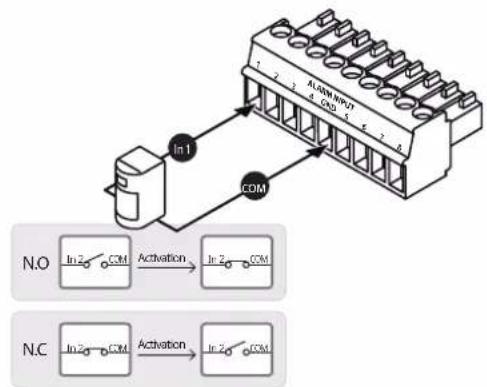
6 Sensor Input
To use alarm input, select the typ eof sensor you wish to use in OSD menu. The sensor types are "Normal Open" and "Normal Close." If sensor type is not selected properly, the alarm can be activated reversely.
flowchart
graph TD
    A["In1"] --> B["COM"]
    C["N.O"] --> D["In2 → COM"]
    D --> E["Activation"]
    F["N.C"] --> G["In2 → COM"]
    G --> H["Activation"]
    I["ALAW NIVOT"] --> J["In1 → COM"]
    J --> K["In2 → COM"]
Please note that short circuit between GND and Input Pin means alarm activation.
3 OSD - Check Points Before Operation
Check Points Before Operation
- Before power is applied, please check the cables carefully.
- The camera ID of the controller must be identical to that of the camera you wish to control. Check the camera ID in "System Information" of the OSD menu.
- If your controller supports multi-protocols, the protocol must be changed to match to that of the camera.
- If you changed camera protocol by changing DIP switch, the change will be effective after you reboot the camera.
- Since the operation method can be different for each controller available, refer to the manual for your controller if camera cannot be controlled properly.
1 Preset and Pattern Function Pre-Check
Check how to operate preset, pattern, scan, and group functions with the keyboard controller or DVR in advance to operate the camera functions using those devices. (Refer to your DVR or system keyboard manual.)
2 Auto Calibration
If the camera is continuously subjected to very high temperatures (over 50^ C or 122^ F) for a long period, the camera can lose focus and produce blurry images. In this case, it is recommended to turn on AUTO CALIBRATION.
If you execute AUTO CALIBRATION, camera will calibrate its focus every six hours.
3 Open OSD Menu
Preset, pattern, scan, group, and alarm input function call all be configured for your camera using the OSD menu. Enter "Preset Key + 0" or "Pattern + 30."
3 OSD - Functions
1 Preset
A maximum of 255 positions can be stored as preset positions. The numbers 1 to 255 can be assigned as preset numbers.
*See section ROOT MENU > FUNCTION SETUP > PRESET SETUP.
1. Set Preset
Method 1) Use keyboard controller:
Refer to keyboard controller manual.
Method 2) Use OSD menu.
2. Run Preset
Method 1) Use keyboard controller:
Preset key + Number key(1\~255)
3. Delete Preset
To delete preset, use OSD menu.
2 Scan
The scan function allows the camera to move repeatedly between 2 preset positions.
See section ROOT MENU > FUNCTION SETUP > SCAN SETUP.
1. Set Scan
To set scan, use OSD menu.
2. Run Scan
Method) Pattern key + Scan number(1\~8) + 10
Ex) Run scan 2 = Pattern key + [12] + Enter key
3. Delete Scan
To delete scan, use OSD menu.
3 Pattern
Pattern function allows the camera to memorize a path created by a joystick controller and then revive the exact path for an assigned time.
See the section ROOT MENU > FUNCTION SETUP > PATTERN SETUP.
1. Set Pattern
To set pattern, use OSD menu.
2. Run Pattern
Method 1) Pattern key + Pattern number(1\~4) + Enter key
Ex) Run pattern 2 = Pattern key + [2] + Enter key
3. Delete Pattern
To delete pattern, use OSD menu.
When the pattern is saved or executed, the pan/tilt is operated with AUTO FLIP-OFF.
4 Group
The group function allows you to run a sequence of presets, patterns, and/or scans.
See the section ROOT MENU > FUNCTION SETUP > GROUP SETUP.
1. Set Group
To set group, use OSD menu.
2. Run Group
Method) Pattern key + [Group number(1\~8) + 20]
Ex) Run group 2 = Pattern key + [22] + Enter key
3. Delete Group
To delete group, use OSD menu.
5 Schedule
The schedule function allows you to run an appropriate function like preset, scan, group, pattern, home, or move at a designated day and time.
See the section ROOT MENU > FUNCTION SETUP > SCHEDULE SETUP.
3 OSD - OSD Display of Main Screen
flowchart
graph TD
    A["Preset Label 1"] --> B["PRESET LABEL"]
    C["Camera ID_Top 2"] --> D["CAMERA ID_TOP"]
    E["Camera ID_Bottom 3"] --> F["CAMERA ID_BOT"]
    G["Date / Time 4"] --> H["F CAM 1"]
    I["Image Flip 5"] --> J["359/180/x100/SE"]
    K["Address 6"] --> L["Pan Angle in Degree"]
    M["PATTERN1"] --> N["Action Title"]
    O["Alarm I/O Information"] --> P["8"]
    Q["Compass Direction"] --> R["9"]
    S["Zoom Magnification"] --> T["10"]
    U["Tilt Angle in Degree"] --> V["11"]
    W["0:1234"] --> X["I:12345678"]
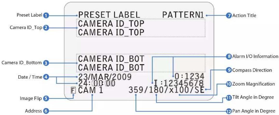
1 Preset Label
- The label stored for a specific preset.
- See section ROOT MENU > FUNCTION SETUP > PRESET SETUP > LABEL.
2 Camera ID\_Top
- If CAMERA ID is set to TOP, Camera ID displayed in this area.
- See section ROOT MENU > DISPLAY SETUP > CAMERA ID.
3 Camera ID\_Bottom
- If Camera ID is set to BOT, Camera ID will display in this area.
- See section ROOT MENU > DISPLAY SETUP > CAMERA ID.
4 Date / Time
- Shows the current date and time.
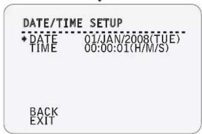
- See section ROOT MENU > SYSTEM SETUP > DATE/TIME SETUP.
5 Image Flip
- Indicates that the image has been reversed by the auto flip function.
- See section ROOT MENU > CAMERA SETUP > IMAGE FLIP.
6 Address
- Displays the current RS-485 address information.
- See section ROOT MENU > SYSTEM INFORMATION.
7 Action Title
- The following are examples of action titles with their descriptions.
| Action Title | Descriptions |
| SET PRESET 123 | Store preset 123. |
| PRESET 123 | It reached preset 123. |
| PATTERN 1 | The camera is running pattern 9. |
| SCN 1/PRESET 123 | The camera is running scan 1. |
| RANGE OVER | The action received is not within the range supported. |
| UNDEFINED | The action received is not defined. |
8 Alarm I/O Information
- This information displays the current status of alarm input and output.
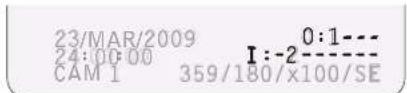
- "I" means input, and "O" means output.
- If the alarm input is ON, it will show the number of the input. If an input is OFF, “-” will be displayed. "O:1---" means output 1 is ON and the other outputs are OFF. EX. When input 2 is ON and output 1 is ON, OSD will display as below.
9 Compass Direction
- Shows the current compass direction of the camera.
- The direction is shown as N(North), S(South), E(East), W(West), NE(Northeast), NW(Northwest), SE(Southeast), or SW(Southwest).
- See section ROOT MENU > SYSTEM SETUP > SET NORTH DIRECTION.
10 Zoom Magnification
Shows the current zoom magnification.
11 Tilt Angle in Degree
Shows the current tilt (0 \~ 180°) angle.
12 Pan Angle in Degree
Shows the current pan (0 \~ 359°) angle.
3 OSD - General Rules of Menu Operation
flowchart
graph TD
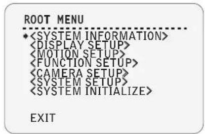
    A["ROOT MENU\n•<SYSTEM INFORMATION>\n<DISPLAY SETUP>\n<MOTION SETUP>\n<FUNCTION SETUP>\n<CAMERA SETUP>\n<SYSTEM SETUP>\n<SYSTEM INITIALIZE>\nEXIT"] -->|Joystick Up| B["ROOT MENU\n•<SYSTEM INFORMATION>\n•<DISPLAY SETUP>\n<MOTION SETUP>\n<FUNCTION SETUP>\n<CAMERA SETUP>\n<SYSTEM SETUP>\n<SYSTEM INITIALIZE>\nEXIT"]
    B -->|Joystick Down| C["DISPLAY SETUP\n•ADDRESS\nCAMERA ID\nPTZ INFORMATION\nACTION TITLE\nPRESET LABEL\nALARM I/O\nDATE/TIME\n<PRIVACY ZONE>\nBACK\nEXIT"]
    C -->|Press Far Key| D["DISPLAY SETUP\n•ADDRESS\nCAMERA ID\nPTZ INFORMATION\nACTION TITLE\nPRESET LABEL\nALARM I/O\nDATE/TIME\n<PRIVACY ZONE>\nBACK\nEXIT"]
    D -->|Press Near/Enter Key| E["DISPLAY SETUP\n•ADDRESS\nCAMERA ID\nPTZ INFORMATION\nACTION TITLE\nPRESET LABEL\nALARM I/O\nDATE/TIME\n<PRIVACY ZONE>\nBACK\nEXIT"]
    E -->|Joystick Up| F["DISPLAY SETUP\n•ADDRESS\nCAMERA ID\nPTZ INFORMATION\nACTION TITLE\nPRESET LABEL\nALARM I/O\nDATE/TIME\n<PRIVACY ZONE>\nBACK\nEXIT"]
    F -->|Joystick Down| G["DISPLAY SETUP\n•ADDRESS\nCAMERA ID\nPTZ INFORMATION\nACTION TITLE\nPRESET LABEL\nALARM I/O\nDATE/TIME\n<PRIVACY ZONE>\nBACK\nEXIT"]
    G -->|Press Near/Enter or Far Key| H["End"]
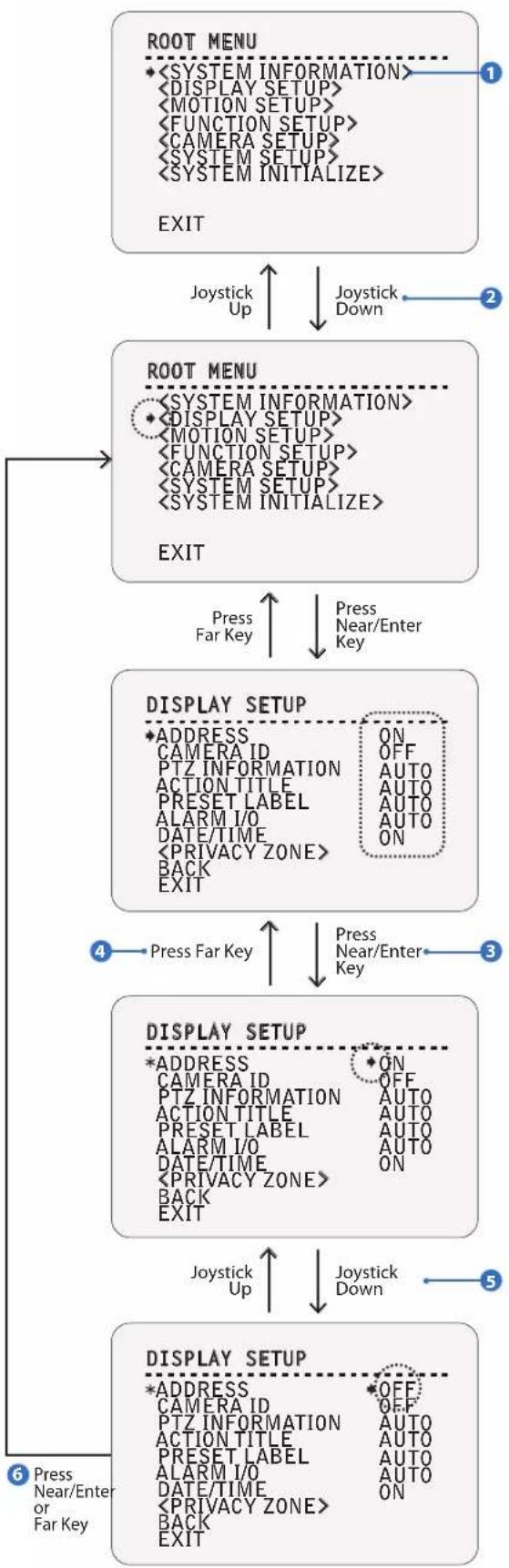
The characters < >, that surround the menu item, indicate that there is a sub menu.
2 Move among the different selections in the menu list using the joystick in the Up/Down or Left/Right direction.
3 To enter a sub-menu, press Near or Enter key.
4 To go back a menu, press Far key.
5 To change a value of an item, move the joystick in the Up/Down direction.
6 Press Near or Enter key to save values and press Far key to cancel values.
3 OSD - ROOT MENU > SYSTEM INFORMATION
1
1
ROOT MENU
1
![SYSTEM INFORMATION FIRMWARE VER 200-39 2011-01-01[21] COLOR SYSTEM NTSC PROTOCOL AUTO BAUD RATE 2400 ADDRESS 1 BACK EXIT](/content/2026/06/1204082/images/414d63db13bda8b3b50ae3b2c2f651272e0120a1482fb03f33a8be8725613973.jpg)
1
SYSTEM INFORMATION
FIRMWARE VER Shows the current firmware version and date of upgrade.
COLOR SYSTEM Shows the current analog video system.
PROTOCOL Shows the current PTZ control protocol.
BAUD RATE Shows the current baud rate of the PTZ control.
ADDRESS Shows the current camera ID of the PTZ control.
3 OSD - DISPLAY SETUP > CAMERA ID
1
2
3
4
5
11 DISPLAY SETUP
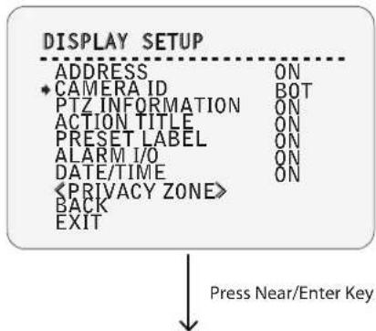
This menu defines what is displayed on the OSD of the main screen. If an item is set as AUTO, the item is displayed only when it is changed.
| ADDRESS | ON / OFF |
| CAMERA ID | BOT / TOP / OFF |
| Select the camera ID location. Refer to "OSD Display of Main Screen." | |
| PTZ INFORMATION | ON / OFF / AUTO |
| ACTION TITLE | ON / OFF / AUTO |
| PRESET LABEL | ON / OFF / AUTO |
| ALARM I/O | ON / OFF / AUTO |
| DATE/TIME | ON / OFF |
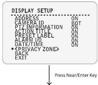
| Starts Privacy Zone Mask Setup Menu. | |
3 CAMERA ID
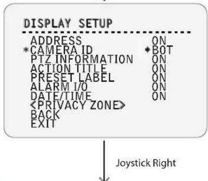
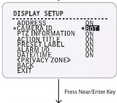
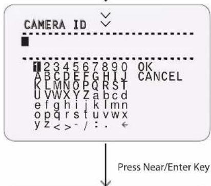
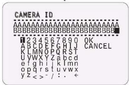
- Set the Camera ID to display on top (TOP) or bottom (BOT). Give the Camera ID a unique name. The menu will appear when TOP or BOT is selected.
- Maximum 48 characters, including space, are allowed.
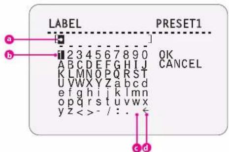
a Current Cursor Position: In the CAMERA ID menu, a black box functions as a cursor. As soon as a character is selected, the cursor moves to the next digit.
b Selecting Alphabet: Move the joystick Up/Down/Left/Right to the appropriate character from the character set you wish to select. To choose the character, press the Near or Enter key.
Space: If you want to use a blank space, choose space character.
Backspace: If you want to delete a character in front, use backspace character.
4 CAMERA ID - Complete Editing
When you complete the camera ID editing, move the cursor to OK and press Near key to save the completed camera ID. To disregard the current change, move the cursor to CANCEL and press the Near key.
3 OSD - DISPLAY SETUP > PRIVACY ZONE
1
2
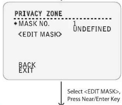
flowchart
graph TD
    A["PRIVACY ZONE"] --> B["• MASK NO."]
    B --> C["<EDIT MASK>"]
    C --> D["1 UNDEFINED"]
    D --> E["BACK EXIT"]
    E --> F["Select <EDIT MASK>, Press Near/Enter Key"]
3
![EDIT MASK 1 MOVE TO TARGET POSITION [ENTER : SELECT] 0/0/x1/E Move Camera to Area to Mask, Press Near/Enter Key](/content/2026/06/1204082/images/9d206a0116cef1d2ecf6ef829146517bb627cc18d4f29b386446651b8e475313.jpg)
4
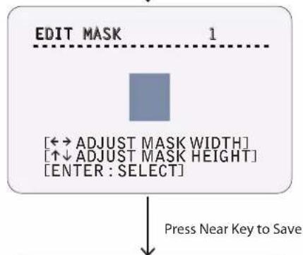
flowchart
graph TD
    A["EDIT MASK 1"] --> B["[←→ ADJUST MASK WIDTH"]
[↑↓ ADJUST MASK HEIGHT]
[ENTER : SELECT]]
    B --> C["Press Near Key to Save"]
5
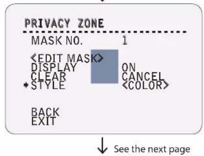
11 DISPLAY SETUP
See the previous page.
3 EDIT MASK - Move to Target Position
Move the camera to the area you wish to mask. Then, the menu to adjust the mask size will be displayed.
If the tilt angle is located in the range between 0^ to 90^ , you can not set up a privacy zone mask.
If a tilt angle over 90^ (image flipped region) is designated, camera will automatically move to that position by moving the pan angle 180^ and adjusting the tilt angle as necessary.
4 EDIT MASK - Adjust Mask Size
Adjust mask size. Use joystick or arrow buttons to adjust mask size.
- Move Joystick Left/Right(◀▶): Adjust Mask Width.
- Move Joystick Up/Down(▲▼): Adjust Mask Height.
To hide a certain zone completely regardless of high speed pan/tilt motions, it is recommended that the size of mask must be 20% bigger than original target size.
It is noted that during pan/tilt control like jog action, the object behind the privacy mask can be disclosed in a short period of time.
2 PRIVACY ZONE
Selects an area in the image to mask.
MASK NO. 1 \~ 8 Selects mask number. If the selected mask has already been saved, camera moves as it was set. Otherwise, UNDEFINED will be displayed under MASK NO.
DISPLAY ON/OFF Sets the camera to display or hide the masks on images.
CLEAR MASK CANCEL / OK Delets data in the selected mask no.
STYLE
3 OSD - DISPLAY SETUP > PRIVACY ZONE
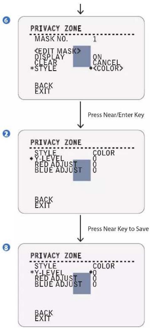
flowchart
graph TD
    A["6"] --> B["PRIVACY ZONE"]
    B --> C["2"]
    C --> D["8"]
    D --> E["Press Near/Enter Key"]
    B --> F["MASK NO. 1"]
    F --> G["<EDIT MASK> DISPLAY ON CLEAR *STYLE <COLOR> BACK EXIT"]
    C --> H["Pressure Near Key to Save"]
    D --> I["PRIVACY ZONE"]
    I --> J["STYLE COLOR Y-LEVEL RED ADJUST BLUE ADJUST 0 0 0"]
    I --> K["BACK EXIT"]
    D --> L["Pressure Near Key to Save"]
    L --> M["PRICE ZONE"]
    M --> N["STYLE COLOR Y-LEVEL RED ADJUST BLUE ADJUST 0 0 0"]
    M --> O["BACK EXIT"]
7 PRIVACY ZONE - STYLE > COLOR Set the color of the mask.
| Y-LEVEL | 0 ~ 100 |
| Set the Y-LEVEL of the mask. | |
| RED ADJUST | 0 ~ 100 |
| BLUE ADJUST | 0 ~ 100 |
3 OSD - MOTION SETUP
1
flowchart
graph TD
    A["MOTION SETUP"] --> B["PRESET LOCK OFF"]
    B --> C["PWR UP ACTION ON"]
    C --> D["AUTO FLIP ON"]
    D --> E["JOG MAX SPEED 140/SEC"]
    E --> F["JOG DIRECTION NORMAL"]
    F --> G["FRZ IN PRESET OFF"]
    G --> H["<PARKING ACTION SETUP>"]
    H --> I["BACK"]
    H --> J["EXIT"]
    I --> K["Press Near/Enter Key"]
    J --> K
    L["PARKING ACTION SETUP"] --> M["PARK ENABLE OFF"]
    M --> N["WAIT TIME 00:10:00"]
    N --> O["PARK ACTION HOME"]
    O --> P["BACK"]
    O --> Q["EXIT"]
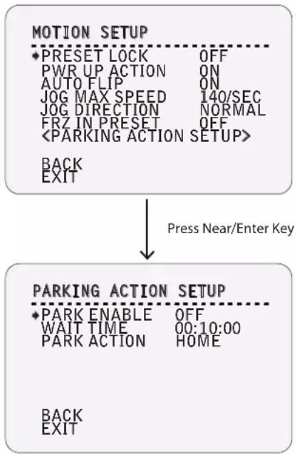
1 MOTION SETUP
Configures the general functions of pan/tilt motions.
| PRESET LOCK | ON / OFF |
| If motion lock is set to ON, it will be impossible to setup or delete a preset, scan, pattern, and/or group. It will only be possible to run those functions. To setup and delete those functions, go to OSD menu. | |
PWR UP ACTION ON / OFF /
This functions sets an action for your camera to execute when it restarts.
- ON: Camera resumes the last action executed before power went down. Most actions such as preset, pattern, scan, and group resume for this function, but jog action does not resume with this function.
- OFF: Camera will move to the home position.
-
If AUTO CAL is turned ON, PWR UP ACTION should also be set as ON. If AUTO CAL is set to ON and PWR UP ACTION is set to PWR P, the camera will most likely cause a malfunction.
If PWR UP ACTION is set as PWR P, FOCUS MODE should be set as AUTO. If FOCUS MODE is set as SEMIAUTO while PWR UP ACTION is set to ON, the camera will most likely cause a malfunction.
AUTO FLIP ON/OFF
When the tilt angle arrives to the top of the tilt orbit (90°), zoom module module camera continues moving opposite of the tilt direction (180°) to continue tracing targets. As soon as zoom module camera passes through the top of tilt direction (90°), images should be reversed automatically and appears on the screen. If this function is set to OFF, tilt movement range is 0° \~ 90°.
JOG MAX SPEED 2/SEC \~ 200/SEC
Sets maximum jog speed. Jog speed is inversely proportional to zoom magnification. As zoom magnification goes up, pan/tilt speed goes down.
JOG DIRECTION INVERSE / NORMAL
If you set this to NORMAL, the view on the screen is moving in the same direction with jog tilting. If INVERSE is selected, the view on the screen is moving in the reverse direction.
When preset movement begins, the camera captures the image of the beginning point. Camera will display the captured image during the preset movement and will not display the images the camera receives during the movement. As soon as the camera stops at the preset end point, the camera begins to display the live images it receives at the end point.
Opens to PARKING ACTION SETUP screen.
2 PARKING ACTION SETUP
If PARK ENABLE is set to ON, camera runs assigned function automatically if there is no PTZ command during assigned WAIT TIME.
PARK ENABLE ON/OFF
WAIT TIME 00:00:05 \~ 04:00:00
The time is displayed in "hh:mm:ss" format, and the time can be changed by 1 second unit.
- To place the cursor on the time marked as shown below, press Near key. 00:10:00
- Move joystick Left/Right to adjust hours, minutes, and seconds.
- Move joystick Up/Down to select the digit.
- Press Near key to save the current setting.
PARKING ACTION HOME / PRESET 1\~128 / SCAN 1\~8 /
PATTERN 1\~4 / GROUP 1\~8
Ex) If HOME is selected for park action, camera will move to home position when there is no PTZ command during the assigned WAIT TIME.
3 OSD - MOTION SETUP
1
2
3
4
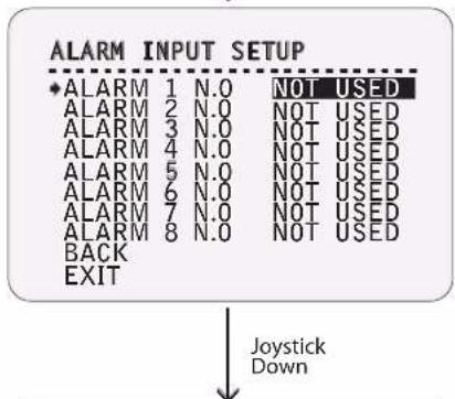
5
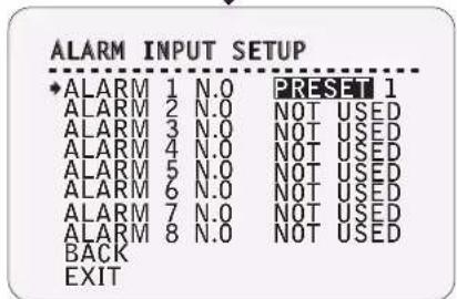
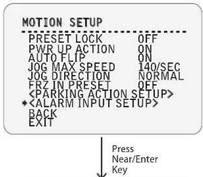
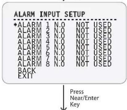
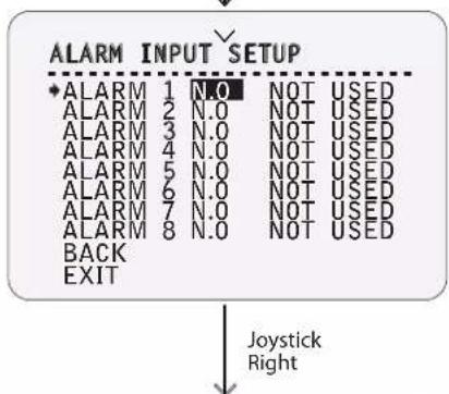
2 ALARM INPUT SETUP
If an external sensor is activated, camera will move to the corresponding action.
Alarm Type: N.O(Normal Open) / N.C(Normal Close) Sets the sensor input type.
Alarm Action NOT USED / HOME / PRESET 1\~128 / SCAN 1\~8 / PATTERN 1\~4 / GROUP 1\~8
For each alarm input, you can assign the counteraction functions (Preset, Scan, Pattern, Group).
3 OSD - FUNCTION SETUP > PRESET SETUP
1
flowchart
graph TD
    A["FUNCTION SETUP\n•<PRESET SETUP>\n<SCAN SETUP>\n<PATTERN SETUP>\n<GROUP SETUP>\n<SCHEDULE SETUP> --> B[BACK\nEXIT"]
    B --> C["Press Near/Enter Key"]
    C --> D["PRESET SETUP\n•PRESET NO.\n<EDIT SCENE>\n1 UNDEFINED\nBACK\nEXIT"]
    D --> E["Select <EDIT SCENE>,\nPress Near/Enter Key"]
2
![EDIT SCENE -PRESET1 MOVE TO TARGET POSITION [NEAR:SELECT/FAR:CANCEL] 0/0/x1/E Press Near/Enter Key](/content/2026/06/1204082/images/76c32adcc048d614b73343bbd839caf03366272a65073817be56ba9399c9e0e4.jpg)
3
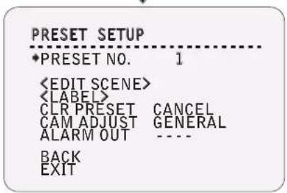
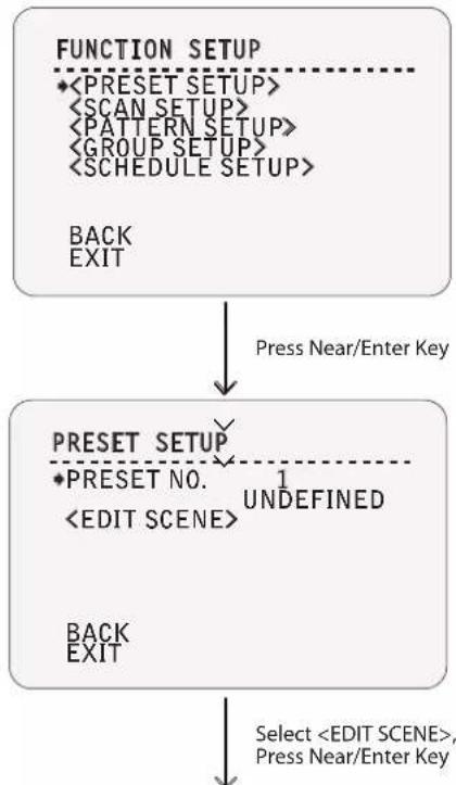
1 FUNCTION SETUP
Configure 5 special functions with this menu.
2 PRESET SETUP - Undefined
127 presets (1\~128) can be assigned excluding the number 95, which is reserved for the OSD menu.
| PRESET NO. 1 ~ 128 (Excluding 95)If a selected preset is already defined, camera moves to pre-defined position, and preset characteristics such as label and relay outputs appear on monitor. Refer screen 4. If a selected preset is not defined, UNDEFINED will appear on the monitor. |
| Redefine the current preset scene position (i.e. PTZ). |
3 EDIT SCENE
-
Using joystick, move camera to the desired position.
-
By pressing Near key, save the current PTZ data.
-
Press Far key to cancel.
PRESET configuration should be used only for Optical Zoom. If Optical Zoom and Digital Zoom are used together and PRESET is set, it is likely to cause malfunction.
4 PRESET SETUP
If the preset is defined, the information will be shown on the OSD menu with the setting, and the alarm device will be activated, if it has been defined.
PRESET NO. 1 \~ 128 (Excluding 95)
Edits Label to show on monitor when preset runs. Maximum ten characters are allowed.
CAM ADJUST
GENERAL / SPECIAL
- WB (White Balance) and AE (Auto Exposure) can be set independently for each preset.
- GENERAL: WB or AE can be set completely and simultaneously for all presets in ROOT MENU > CAMERA SETUP menu.
- SPECIAL: WB or AE can be set independently or separately for each preset in each preset setup menu.
- Each special WB and AE value should the activated correspondingly when camera arrives at each preset location. During jog operation, the general WB and AE value should be applied.
- The special WB and AE values should not be changed when the general WB and AE value is changed. If SPECIAL is selected, the menu to set the special WB and AE appears on the monitor.
ALARM OUT
---- \~1234
The status of four alarm outputs can be freely controlled in conjunction with preset run. The character "-" means the alarm output is OFF, and the number which represents the alarm means ON.
Ex) "- 2 3 - " means output relay 2 and 3 will be ON, and 1 and 4 will be OFF, when you run this preset.
3 OSD - FUNCTION SETUP > PRESET SETUP
1
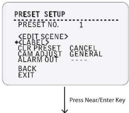
flowchart
graph TD
    A["PRESET SETUP"] --> B["PRESET NO. 1"]
    B --> C["<EDIT SCENE>"]
    C --> D["<LABEL>"]
    D --> E["CLR PRESET CANCEL"]
    E --> F["CAM ADJUST GENERAL"]
    F --> G["ALARM OUT ----"]
    G --> H["BACK"]
    H --> I["EXIT"]
    I --> J["Press Near/Enter Key"]
2
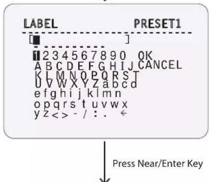
3
![[SKY■] 1 2 3 4 5 6 7 8 9 0 *OK A B C D E F G H I J C A N C E L K L M N O P Q R S T U V W X Y Z a b c d e f g h i j k l m n o p q r s t u v w x y z < > - / : .](/content/2026/06/1204082/images/bf8195fb048c245e9e39d9b19db69459c3ac67cb5783620cf0556b2c3cab0df7.jpg)
2 LABEL
- Edits the label to display on the monitor when camera arrives at presets.
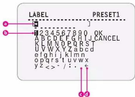
a Current Cursor Position: In edit label menu, a black box acts as a cursor. As soon as you select a character, the cursor moves to the next digit.
b Selecting Alphabet: Using the joystick, move to an appropriate character from the character set. To select the character, press the Near or Enter key.
Space: If you want to use blank, choose space character.
Backspace: If you want to delete a character in front of the black box, use backspace character.
3 LABEL – Complete Editing
If you complete the label editing, move the cursor to OK and press NEAR key to save the completed label. To disregard the current change, move the cursor to CANCEL and press the Near key.
1
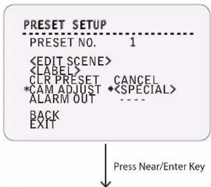
flowchart
graph TD
    A["PRESET SETUP"] --> B["PRESET NO. 1"]
    B --> C["<EDIT SCENE>"]
    C --> D["<LABEL>"]
    D --> E["CLR PRESET CANCEL"]
    E --> F["*CAM ADJUST *<SPECIAL>"]
    F --> G["ALARM OUT ----"]
    G --> H["BACK"]
    H --> I["EXIT"]
    I --> J["Press Near/Enter Key"]
2
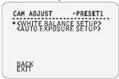
2 CAM ADJUST
Edits label to show on monitor when the camera arrives at the presets.
3 OSD - FUNCTION SETUP > SCAN SETUP
1
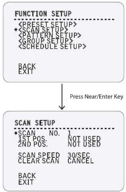
flowchart
graph TD
    A["FUNCTION SETUP"] --> B["<PRESET SETUP><br>• <SCAN SETUP><br>• <PATTERN SETUP><br>• <GROUP SETUP><br>• <SCHEDULE SETUP>"]
    B --> C["BACK<br>EXIT"]
    D["SCAN SETUP"] --> E["• SCAN NO. 1<br>1ST POS. NOT USED<br>2ND POS. NOT USED"]
    D --> F["SCAN SPEED 30/SEC<br>CLEAR SCAN CANCEL"]
    D --> G["BACK<br>EXIT"]
    H["Press Near/Enter Key"] --> I
2 SCAN SETUP
With the scan function, you can set the camera to move between 2 preset positions repeatedly.
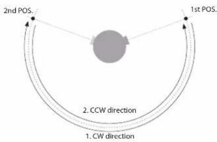
When the scan function runs, the camera moves from the preset assigned as the 1st point to the preset assigned as the 2nd point in CW (clockwise) direction. Then, the camera moves from the preset assigned as the 2nd point to the preset assigned as the 1st point in CCW (counterclockwise) direction.
In case the preset assigned as the 1st point is same as the preset assigned as the 2nd point, the camera turns on its axis by 360° in CW direction and then it turns on its axis by 360° in CCW direction.
SCAN NO.
1\~8
Selects the scan number to edit. If a selected scan has not been defined, NOT USED is displayed in 1st position and 2nd position.
1ST POS. / 2ND POS.
PRESET 1 \~ 128 / NOT USED
Set up the 2nd Position for scan function. If a selected preset is not defined, UNDEFINED will be displayed as shown below.
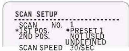
SCAN SPEED
1/SEC \~ 180/SEC
Sets the speed of the scan.
CLEAR SCAN
CANCEL / OK
Deletes the current scan data.
3 OSD - FUNCTION SETUP > PATTERN SETUP
1
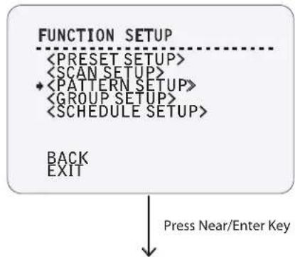
flowchart
graph TD
    A["FUNCTION SETUP"] --> B["<PRESET SETUP>"]
    A --> C["<SCAN SETUP>"]
    A --> D["• <PATTERN SETUP>"]
    A --> E["<GROUP SETUP>"]
    A --> F["<SCHEDULE SETUP>"]
    G["BACK"] --> H["EXIT"]
    I["Press Near/Enter Key"] --> J
2
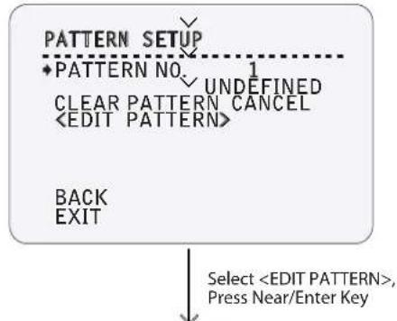
flowchart
graph TD
    A["PATTERN SETUP"] --> B["♦PATTERN NO. 1"]
    B --> C["CLEAR PATTERN CANCEL"]
    C --> D["<EDIT PATTERN>"]
    D --> E["BACK"]
    D --> F["EXIT"]
    G["Select <EDIT PATTERN>, Press Near/Enter Key"] --> H
3
![EDIT PATTERN 1 MOVE TO START POSITION [NEAR:START/ FAR:CANCEL] 0/0/×IEE Move Camera to Area, Press Near/Enter Key](/content/2026/06/1204082/images/28b1c7b3f252ab6f9d734ab03764f0c6c47532e0a59562edac071cd582547279.jpg)
4
![EDIT PATTERN 1 [NEAR:SAVE / FAR:DELETE] 0/0/×1%E Record the Path of the Pattern by Camera Control](/content/2026/06/1204082/images/02fcd169793b9da888363941de1750448f84380dff3191b1e0a8c0e368157ff1.jpg)
5
![EDIT PATTERN 1 [NEAR:SAVE / FAR:DELETE] 0/0/×IEE](/content/2026/06/1204082/images/5a4173fc115ea726814d90b3c1912afcec00aa2079ed532ce57a7cc06bf35527.jpg)
2 PATTERN SETUP
Pattern function is when a camera memorizes the path (mostly curve path) created by a joystick controller and revives the path exactly as it memorized for an assigned time.
4 patterns are available and maximum 1000 communication commands can be stored in a pattern.
PATTERN NO. 1 \~ 4 Select pattern number to edit. If a selected pattern number is not defined, UNDEFINED will be displayed under selected pattern number.
CLR PATTERN CANCEL / OK Deletes data in the current pattern.
3 EDIT PATTERN - Select the Position
- By using joystick, move to the start position with appropriate zoom.
- To start the pattern recording, press Near or Enter key.
- To exit this menu, press Far key.
4 EDIT PATTERN - Records
- Move the camera with joystick of the controller or run preset function to memorize the path (mostly curve path) in a selected pattern.
- The total memory size and the rest memory size is displayed in the form of a bar.
- To save data and exit, press Near key.
- To cancel recording and delete the recorded data, press Far key.
3 OSD - FUNCTION SETUP > GROUP SETUP
1
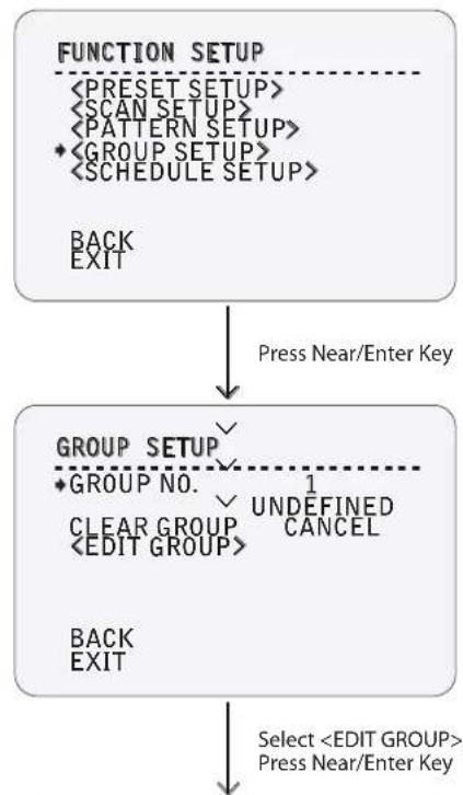
flowchart
graph TD
    A["FUNCTION SETUP\n<PRESET SETUP>\n<SCAN SETUP>\n<PATTERN SETUP>\n*<GROUP SETUP>\n<SCHEDULE SETUP>\nBACK\nEXIT"] --> B["Press Near/Enter Key"]
    B --> C["GROUP SETUP\n*GROUP NO.\nCLEAR GROUP\n<EDIT GROUP>\n1 UNDEFINED\nCANCEL\nBACK\nEXIT"]
    C --> D["Select <EDIT GROUP>\nP Press Near/Enter Key"]
2
3
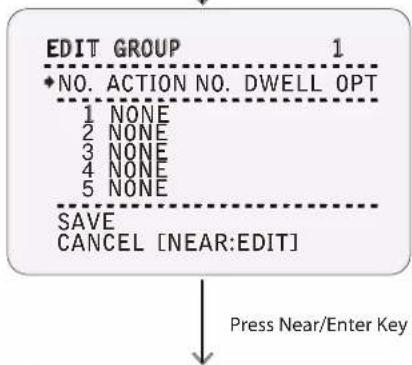
flowchart
graph TD
    A["EDIT GROUP 1"] --> B["NO. ACTION NO. DWELL OPT"]
    B --> C["1 NONE"]
    B --> D["2 NONE"]
    B --> E["3 NONE"]
    B --> F["4 NONE"]
    B --> G["5 NONE"]
    B --> H["SAVE"]
    B --> I["CANCEL [NEAR:EDIT"]]
    H --> J["Press Near/Enter Key"]
    I --> J
4
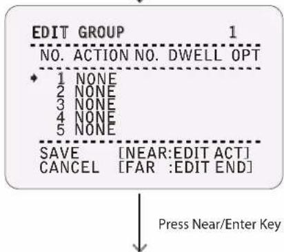
flowchart
graph TD
    A["EDIT GROUP"] --> B["NO. ACTION NO. DWELL OPT"]
    B --> C["1 NONE"]
    B --> D["2 NONE"]
    B --> E["3 NONE"]
    B --> F["4 NONE"]
    B --> G["5 NONE"]
    C --> H["SAVE [NEAR:EDIT ACT"]]
    C --> I["CANCEL [FAR :EDIT END"]]
    H --> J["Press Near/Enter Key"]
    I --> J
5
![EDIT GROUP 1 NO. ACTION NO. DWELL OPT + 1 NONE 2 NONE 3 NONE 4 NONE 5 NONE SAVE [←→: MOVE CURSOR CANCEL [↑↓: CHANGE VAL.]](/content/2026/06/1204082/images/4ca7cbfc413abae9d36e692b6eb620dadb774c90e31e232b8ea3be88d6f034b0.jpg)
2 GROUP SETUP SCREEN
The group function allows you to run sequence of presets, pattern, and/or scans. Maximum 8 groups can be stored. Each group can have a maximum of 20 action entities which can be preset, pattern, or scan.
The preset speed and the repeat number of patter & scan can be configured in group setup. Dwell time between actions can also be adjusted.
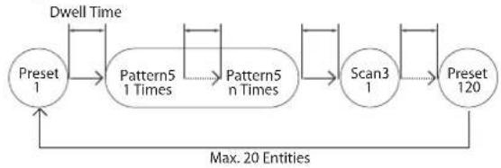
flowchart
graph TD
    A["Preset 1"] --> B["Pattern5 1 Times"]
    B --> C["Pattern5 n Times"]
    C --> D["Scan3 1"]
    D --> E["Preset 120"]
    E --> F["Dwell Time"]
    F --> A
    style A fill:#fff,stroke:#000
    style B fill:#fff,stroke:#000
    style C fill:#fff,stroke:#000
    style D fill:#fff,stroke:#000
    style E fill:#fff,stroke:#000
    style F fill:#fff,stroke:#000
GROUP NO. 1 \~ 8 Selects group number to edit. If a selected group number is not defined, UNDEFINED will be displayed under the selected group number.
CLEAR GROUP CANCEL / OK Deletes data in the current group.
3 EDIT GROUP - Initial Screen
Select a # from the list to begin group setup.
| ACTION NO. | NONE / PRESET 1~128(Excluding 95) / PATTERN 1~4 / SCAN 1~4 |
| DWELL TIME | 00:03 ~ 04:00 (min:sec) |
| Sets dwell time between function by moving joystick up/down. | |
| OPT | PRESET: 1~360 / PATTERN & SCAN: 1~255 |
| Represents preset speed (1~360) when preset is selected. It should be the number of repetition (1~255), when pattern or scan is selected for ACTION. | |
4 EDIT GROUP – Select Function Sequence
Note that a maximum of 20 functions are allowed in a group. Move cursor up/down and press Near or Enter key to set up.
56 EDIT GROUP - Assign Function
Set up ACTION, DWELL, and OPT. Note that selected item is displayed in reverse. Move cursor left/right to select items and move cursor up/down to change each value.
3 OSD - FUNCTION SETUP > GROUP SETUP
6
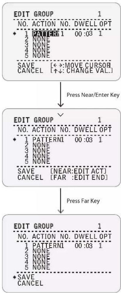
flowchart
graph TD
    A["EDIT GROUP\n1\nNO. ACTION NO. DWELL OPT\n♦ 1 PATTERN1 00:03 1\n2 NONE\n3 NONE\n4 NONE\n5 NONE\nSAVE [←→:MOVE CURSOR\nCANCEL [↑↓:CHANGE VAL."]]
    ↓ Press Near/Enter Key] --> B["EDIT GROUP\n1\nNO. ACTION NO. DWELL OPT\n♦ 1 PATTERN1 00:03 1\n2 NONE\n3 NONE\n4 NONE\n5 NONE\nSAVE [NEAR:EDIT ACT"]\nCANCEL["FAR :EDIT END"]]
    B --> C["EDIT GROUP\n1\nNO. ACTION NO. DWELL OPT\n♦ 1 PATTERN1 00:03 1\n2 NONE\n3 NONE\n4 NONE\n5 NONE\nSAVE [NEAR:EDIT ACT"]\nCANCEL["FAR :EDIT END"]]
    C --> D["EDIT GROUP\n1\nNO. ACTION NO. DWELL OPT\n♦ 1 PATTERN1 00:03 1\n2 NONE\n3 NONE\n4 NONE\n5 NONE\nSAVE [NEAR:EDIT ACT"]\nCANCEL["FAR :EDIT END"]]
    D --> E["EDIT GROUP\n1\nNO. ACTION NO. DWELL OPT\n♦ 1 PATTERN1 00:03 1\n2 NONE\n3 NONE\n4 NONE\n5 NONE\nSAVE [NEAR:EDIT ACT"]\nCANCEL["FAR :EDIT END"]]
7 EDIT GROUP - Selects Function Sequence
When you finish setting up an ACTION, press Near or Enter key. Move cursor up/down to select another ACTION NO. and repeat steps4\~ step6 to edit the selected group.
8 EDIT GROUP - Saves the Setting
After completing the setup of all actions, press Far key to exit. Then, move the cursor to SAVE. Press Near or Enter key to save the data.
3 OSD - FUNCTION SETUP > SCHEDULE SETUP
1
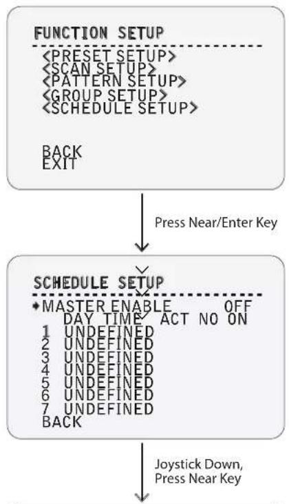
flowchart
graph TD
    A["FUNCTION SETUP\n<PRESET SETUP>\n<SCAN SETUP>\n<PATTERN SETUP>\n<GROUP SETUP>\n<SCHEDULE SETUP>\nBACK\nEXIT"] --> B["Press Near/Enter Key"]
    B --> C["SCHEDULE SETUP\n*MASTER ENABLE OFF\nDAY TIME ACT NO ON\n1 UNDEFINED\n2 UNDEFINED\n3 UNDEFINED\n4 UNDEFINED\n5 UNDEFINED\n6 UNDEFINED\n7 UNDEFINED\nBACK"]
    C --> D["Joystick Down,\nPress Near Key"]
2
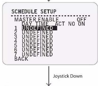
flowchart
graph TD
    A["SCHEDULE SETUP"] --> B["MASTER ENABLE OFF"]
    B --> C["DAY TIME ACT NO ON"]
    C --> D["1 UNDEFINED"]
    C --> E["2 UNDEFINED"]
    C --> F["3 UNDEFINED"]
    C --> G["4 UNDEFINED"]
    C --> H["5 UNDEFINED"]
    C --> I["6 UNDEFINED"]
    C --> J["7 UNDEFINED"]
    C --> K["BACK"]
    L["Joystick Down"] --> M
3
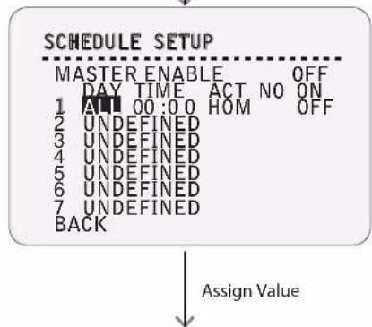
flowchart
graph TD
    A["SCHEDULE SETUP"] --> B["MASTER ENABLE OFF"]
    B --> C["DAY TIME ACT NO ON"]
    C --> D["1 AM 00:00 HOM OFF"]
    D --> E["2 UNDEFINED"]
    E --> F["3 UNDEFINED"]
    F --> G["4 UNDEFINED"]
    G --> H["5 UNDEFINED"]
    H --> I["6 UNDEFINED"]
    I --> J["7 UNDEFINED"]
    J --> K["BACK"]
    K --> L["Assign Value"]
4
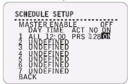
2 SCHEDULE SETUP SCREEN
The schedule function allows you to run an appropriate function like preset, scan, pattern, or group at a designated day and time.
EX) If you set the rule "Tuesday at 9:00AM" and "Preset 1 (EX: Main Gate)", the camera will move to the main gate every Tuesday at 9:00 AM. If you choose weekday, camera will move to main gate everyday except on weekends.
It is noted that due to the real time clock (ROOT MENU > SYSTEM SETUP > DATA/TIME SETUP), the time data will be kept regardless of a blackout. The initial time and day setup is essential to proper schedule function.
| MASTER ENABLE | ON / OFF |
| Decide whether schedule function is active or not. | |
| DAY | UNDEFINED / ALL / WKD / SUN ~ MON |
| Set the day for scheduling. | |
| - Undefined: Inactivate. | |
| - All: Applies to every day of the week. | |
| - WKD: Applies to every day except Saturday and Sunday. | |
| - SUN-MON: Applies to the designated day only. | |
| TIME | 00:00 ~ 23:59 (hour:min) |
| Set the time. | |
| ACT NO | HOM(HOME) / PRS(Preset) 1~128(Excluding 95)/ SCN(Scan) 1~8 / PTN(Pattern) 1~4/GRO(Group) 1~8 |
| Set the function and number. | |
| ON | ON /OFF |
| Turn ON / OFF this rule. | |
4 5 SCHEDULE SETUP - Assign Value
Each field (DAY, TIME, ACT, NO, ON) can be selected by left/right keys, and the values in the field are changed using up/down keys.
3 OSD - FUNCTION SETUP > SCHEDULE SETUP
6
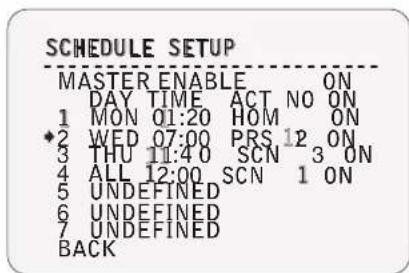
EXAMPLE:
The second rule means camera will move to preset 12 at 7:00 every wednesday.
If the rules conflict with each other, the higher number will have priority over the others.
If you assign an undefined function, there will be no action that takes place.
3 OSD - CAMERA SETUP > WB SETUP
1
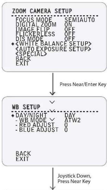
flowchart
graph TD
    A["ZOOM CAMERA SETUP"] --> B["FOCUS MODE SEMIAUTO"]
    A --> C["DIGITAL ZOOM ON"]
    A --> D["IMAGE FLIP OFF"]
    A --> E["FLICKERLESS OFF"]
    A --> F["DIS MODE OFF"]
    A --> G["<WHITE BALANCE SETUP><br>    <AUTO EXPOSURE SETUP><br>    <SPECIAL><br>    BACK<br>    EXIT"]
    B --> H["Press Near/Enter Key"]
    C --> I["✓"]
    I --> J["WB SETUP"]
    J --> K["DAY/NIGHT DAY"]
    K --> L["- WB MODE ATW2"]
    K --> M["- RED ADJUST 0"]
    K --> N["- BLUE ADJUST 0"]
    J --> O["BACK<br>EXIT"]
    J --> P["Joystick Down,<br>Press Near Key"]
2
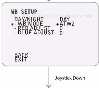
flowchart
graph TD
    A["WB SETUP"] --> B["DAY/NIGHT"]
    A --> C["DAY"]
    B --> D["*- WB MODE"]
    B --> E["◆ ATW2"]
    C --> F["- RED ADJUST 0"]
    C --> G["- BLUE ADJUST 0"]
    H["BACK"] --> I["EXIT"]
    J["Joystick Down"] --> K
3
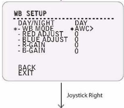
4
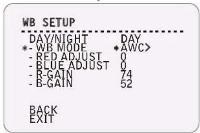
1 ZOOM CAMERA SETUP
Setup the general functions of zoom camera module.
FOCUS MODE
AUTO / MANUAL / SEMIAUTO
Sets the camera focus mode.
- SEMIAUTO: Alternates the focus mode automatically from MANUAL to AUTO. MANUAL activates during preset operation, and AUTO activates when jog operation begins.
- MANUAL: A unique focus can be set for a specific preset. When MANUAL is selected as the focus mode, camera will go to the set focus for the corresponding preset.
DIGITAL ZOOM
ON / OFF
Sets digital zoom function to ON or OFF. If this is set to OFF, optical zoom function runs, but zoom function stops at the end of optical zoom magnification.
If DIGITAL ZOOM is set to OFF, DIS will turn off automatically.
IMAGE FLIP
ON / OFF
Set the image to display as is or in reverse.
FLICKERLESS
ON / OFF
Turn ON or OFF Flickerless function. If this is turned on, AEbecomes the priority shutter mode, and shutter speed value will be fixed to 1/100 seconds.
DIS
ON / OFF
Sets the Digital Image Stabilization mode.
If DIS MODE is set to ON, DIGITAL ZOOM will turn off automatically.
Opens WHITE BALANCE SETUP screen.
Opens AUTO EXPOSURE SETUP screen.
Opens SPECIAL SETUP screen.
2 WB SETUP - DAY
DAY/NIGHT
DAY / NIGHT
The day and night mode can be set independently.
Night mode will only be deactivated if AGC in CAMERA SETUP is set to OFF or FIX.
WB MODE
ATW1 / ATW2 / AWC / 3200K / 5600K / OFF
- ATW1: The color temperature is adjusted automatically between 2500K and 9300K.
- ATW2: The color temperature is adjusted automatically between 2000K and 10000K.
- AWC: The color temperature is adjusted automatically. Then, adjusted value of R-GAIN and B-GAIN are maintained. Gain value can be adjusted manually by the user. It can be fixed as 3200K or 5600K.
- OFF: Only activated when NIGHT is selected. At night, the setting will be same as day's setting.
RED/BLUE ADJUST
-32 \~ +32
In every mode except OFF, users can adjust the red/blue color value to have the image they want.
R/B - GAIN
0\~1000
If AWC is ON, the adjusted value will be marked. Also, the user can adjust the values even after it has been adjusted automatically.
3 OSD - CAMERA SETUP > WB SETUP
6
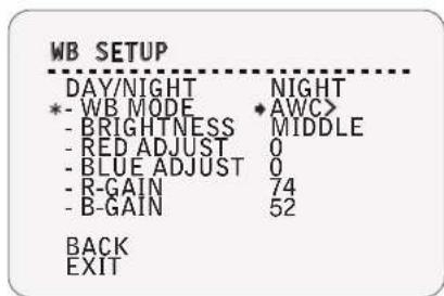
6 WB SETUP - NIGHT
BRIGHTNESS
LOW / MIDDLE / HIGH
When NIGHT is selected, it sets the criterion of the automatic day/night selection.
If set to LOW, the image has to be very dark to be recognized as night among the 3 settings. If set to HIGH, the image will be recognized as night even though it is a little dark.
3 OSD - CAMERA SETUP > AE SETUP
1
flowchart
graph TD
    A["AE SETUP"] --> B["IRIS"]
    A --> C["DAY/NIGHT"]
    A --> D["MOTION"]
    A --> E["SHUTTER SPD"]
    A --> F["SENS-UP"]
    A --> G["AUTOx4"]
    A --> H["BACK"]
    A --> I["EXIT"]
    H --> J["Press Near/Enter Key"]
    I --> J
2
3
flowchart
graph TD
    A["BLC AREA"] --> B["IRIS"]
    A --> C["<ALC>"]
    A --> D["BACK"]
    A --> E["EXIT"]
    F["Select AREA > USER. Press Near/Enter Key"]
4
flowchart
graph TD
    A["BLC AREA"] --> B["MOVE TO TARGET POSITION [ENTER : SELECT"]]
    B --> C["Move Camera to BLC Area, Press Near/Enter Key"]
5
![BLC AREA [← → ADJUST MASK WIDTH] [↑↓ ADJUST MASK HEIGHT] [ENTER : SELECT]](/content/2026/06/1204082/images/2e23edf5e7710e3f08483a9f80420ad13ac8c68573a8d77b6dc56a276f418616.jpg)
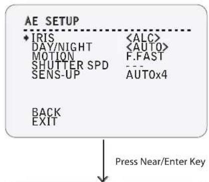
1 AE SETUP
IRIS
ALC / MANUAL
See below"
2 AE SETUP
- IRIS > ALC."
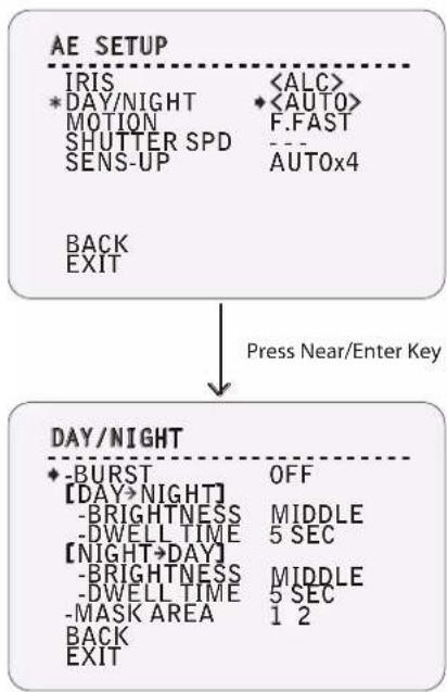
DAY/NIGHT
DAY / NIGHT / AUTO
Color filter or B/W filter can be selected. If DAY/NIGHT is set to AUTO, starts 'DAY/NIGHT' editing. See the next page "2 DAY/NIGHT."

This is changed to AGC or MOTION according to the SENS-UP setting.
AGC
VERY LOW / LOW / MIDDLE / HIGH /
VERY HIGH / USER 1\~16 / FIX 1\~16
Enhances the brightness of the image by amplifying gain when the illumination is low.
MOTION
S.SLOW / SLOW / NORMAL / FAST / F.FAST
If MOTION is set to S.SLOW, the shutter speed will be slower to obtain more light. There will be less noise, but this can cause the ghost effect of the moving object.
If MOTION is set to F.FAST, there will be less noise, but this will reduce the ghost effect for any moving object.
SHUTTER SPD
If this speed is fater, the moving object can be photographed without the ghost effect. However, the images can be dark if the scene lacks sufficient lighting.

If SENS-UP is set to AUTO, SHUTTER SPD is deactivated.
SENS-UP
OFF / AUTO x2 \~ AUTO x256 / FIX x2 \~ FIX x256
Activates the slow shutter function when luminance of the image is too dark for the CCD to accumulate the amount of light it is set to obtain.
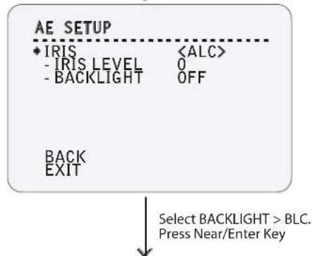
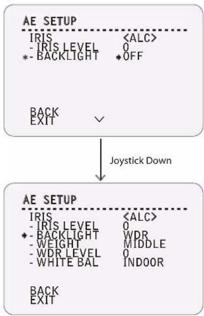
2 AE SETUP - IRIS > ALC
If ALC is selected, the iris will be controlled automatically.
IRIS LEVEL
-32\~+32
BACKLIGHT
OFF / BLC / WDR
This function improves the backlight effect, which is when the subject is dark on the monitor because the intensive backlight.
- BLC: You can select the desired area you wish to brighten. If it is set on a bright area, note that the area will appear even brighter.
- WDR: See "AE SETUP - IRIS > ALC > BACKLIGHT > WDR" on the next page.
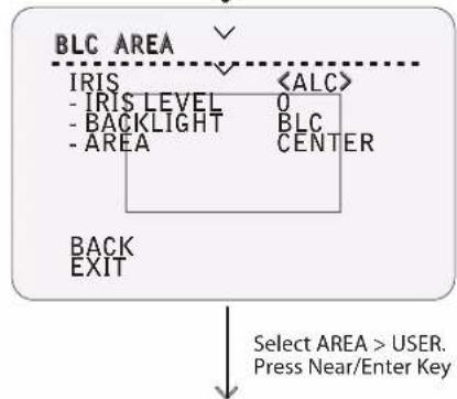
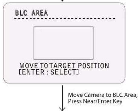
3 BLC AREA
AREA
TOP / BOTTOM / LEFT / RIGHT / USER
If set to USER, the user can set the specific area.
See the screens 4 5 on this page.
3 OSD - CAMERA SETUP > AE SETUP
1
flowchart
graph TD
    A["AE SETUP"] --> B["IRIS"]
    A --> C["•DAY/NIGHT"]
    A --> D["MOTION"]
    A --> E["SHUTTER SPD"]
    A --> F["SENS-UP"]
    A --> G["BACK"]
    A --> H["EXIT"]
    I["Press Near/Enter Key"] --> J["DAY/NIGHT"]
    J --> K["-BURST"]
    J --> L["[DAY>NIGHT"]]
    J --> M["-BRIGHTNESS"]
    J --> N["-DWELL TIME"]
    J --> O["[NIGHT>DAY"]]
    J --> P["-BRIGHTNESS"]
    J --> Q["-DWELL TIME"]
    J --> R["-MASK AREA"]
    J --> S["BACK"]
    J --> T["EXIT"]
    U["<<ALC>>"] --> V["•"]
    V --> W["<<AUTO>>"]
    V --> X["F.FAST"]
    V --> Y["---"]
    V --> Z["AUTOx4"]
    AA["OFF"] --> AB["MIDDLE"]
    AA --> AC["5 SEC"]
    AA --> AD["MIDDLE"]
    AA --> AE["5 SEC"]
    AA --> AF["1 2"]
2 DAY/NIGHT
The camera automatically detects the change by the brightness of the scene.
| BURST | ON / OFF |
| If BURST is set to ON, the burst signal is produced although the camera is changed to B/W filter. | |
| BRIGHTNESS | LOW / MIDDLE / HIGH |
| As the camera switches from Color to B/W with BRIGHTNESS set as LOW, the images will appear darker. As the camera switches from B/W to Color with BRIGHTNESS set as HIGH, the image will appear brighter. | |
| DWELL TIME | 2 SEC / 3 SEC / 5 SEC / 10 SEC / 15 SEC / 20 SEC / 25 SEC / 30 SEC |
| When the switching criterions are satisfied, the filter is changed after the status is maintained during the dwell time. | |
| MASK AREA | 1 / 2 |
| If streetlights or traffic lights are present in a night scene, the mode might not change to B/W. In this incident, setting MASK AREA to those lights will correct the problem. | |
| ☒ If BACKLIGHT is set to BLC, MASK AREA function is deactivated. |
1
flowchart
graph TD
    A["AE SETUP"] --> B["IRIS <ALC>"]
    B --> C["- IRIS LEVEL 0"]
    B --> D["*- BACKLIGHT ◆OFF"]
    A --> E["BACK EXIT ✓"]
    E --> F["Joystick Down"]
    G["AE SETUP"] --> H["IRIS <ALC>"]
    H --> I["- IRIS LEVEL 0"]
    H --> J["*- BACKLIGHT WDR"]
    H --> K["- WEIGHT MIDDLE"]
    H --> L["- WDR LEVEL 0"]
    H --> M["- WHITE BAL INDOOR"]
    G --> N["BACK EXIT"]
2 AE SETUP - IRIS > ALC > BACKLIGHT > WDR
In WDR mode, the brightness is adjusted in all area of the picture by combining high speed shutter and low speed shutter.
| WEIGHT | LOW / MIDDLE / HIGH |
| If 'WEIGHT is set to HIGH, the area applying high speed shutter is expanded. | |
| WDR LEVEL | -9 ~ +9 |
| As WDR LEVEL gets higher, the speed of the high speed shutter gets faster. | |
| WHITE BAL | INDOOR / OUTDOOR |
| If WHITE BAL is set to INDOOR, the color temperature adjusts based on the darker areas. If WHITE BAL is set to OUTDOOR, the color temperature adjusts based on the brighter areas. | |
| ☒ | When WDR is used, the internally operating VPS function stops. |
3 OSD - CAMERA SETUP > SPECIAL
1
flowchart
graph TD
    A["ZOOM CAMERA SETUP"] --> B["FOCUS MODE SEMIAUTO"]
    A --> C["DIGITAL ZOOM ON"]
    A --> D["IMAGE FLIP OFF"]
    A --> E["FLICKERLESS OFF"]
    A --> F["DIS MODE OFF"]
    A --> G["<WHITE BALANCE SETUP>"]
    A --> H["<AUTO EXPOSURE SETUP>"]
    A --> I["<SPECIAL>"]
    I --> J["BACK"]
    I --> K["EXIT"]
    A --> L["Press Near/Enter Key"]
    M["SPECIAL"] --> N["DNR MIDDLE"]
    M --> O["ZOOM SPEED 4"]
    M --> P["DETAIL 2"]
    M --> Q["PIP OFF"]
    M --> R["POSI/NEGA +"]
    M --> S["BACK"]
    M --> T["EXIT"]
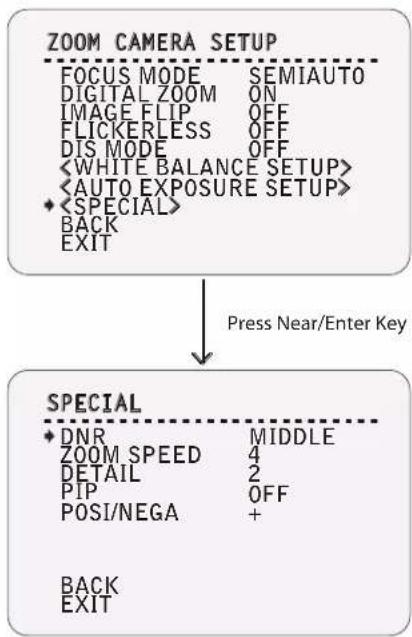
2 SPECIAL
Sets the special function(s) related to the image quality.
DNR OFF / LOW / MIDDLE / HIGH / USER 1\~16 Reduces the noise caused by AGC. If set to HIGH, the noise will be reduced, but the ghost effect on moving objects will be increased.
ZOOM SPEED 1 \~ 4 The speed it takes to adjust the zoom in/zoom out. 1 is the slowest, and 4 is the fastest.
DETAIL 0 \~ 3 The distinction is separated into 4 levels. If the level is high, the outline is clear but the noise is increased.
PIP ON/OFF The color range of the noise caused by AGC can be reduced. If set to HIGH, the color range of the noise will increase, but the overall quality of the color will also decrease.
POSI/NEGA + / - If set as +, the camera will produce the normal image; however, if set as -, the brightness signal and color signal of the produced image will be reversed.
3 OSD - SYSTEM SETUP
1
2
3
4
![EDIT PASSWORD ■ ] 1234567890 QK A B C D E F G H I J C A N C E L K L M N O P O R S T U V W X Y Z a b c d D I S A B I E e f g h i j k l m n o p q r s t u v w x y z < > - / : . ←](/content/2026/06/1204082/images/0748dd76cc7c4f17a131774410f05f24823d488f222d8a46fd58e8045fce4499.jpg)
1
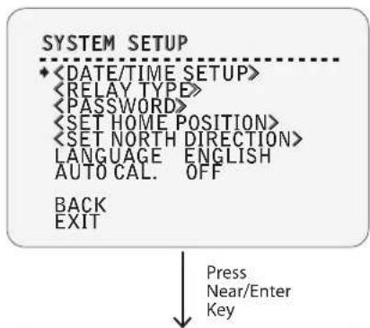
SYSTEM SETUP
LANGUAGE
ENGLISH / ESPAÑOL / FRANÇAIS / DEUTSCH / ITALIANO / PYCCKIЙ / PORTUGUÊS
You can select a preferred language for the OSD display. After selecting a language, press Near or Enter key.
AUTO CAL. ON/OFF
If the camera is continuously subjected to very high temperatures (over 50°C or 122°F) for a long period of time, it is possible for the camera to lose focus and produce blurry images. When this happens, it is recommended to turn ON the auto calibration feature.
If AUTO CAL is set to ON, it will be conducted for 10 seconds every 24 hours.
- During auto calibration, unexpected images can appear due to unordinary PTZ movement.
- During auto calibration, the figures "A.C" will be displayed on the bottom left corner of the screen.
- During auto calibration, some functions including PTZ cannot be executed.
2
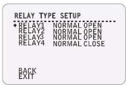
RELAY TYPE SETUP
RELAY1, 2, 3, 4 NORMAL OPEN (N.O) / NORMAL CLOSE (N.C) Define the type of relay output for each of the four relays.
3
EDIT PASSWORD
Set a password that consist of 4 characters. If this function is set to ENABLE, the password is required whenever you open the OSD menu.
The default password is "4321," and the master password is "-- > g."
3 OSD - SYSTEM SETUP
5
SET HOME POSOTION
MOVE TOTARGET POSITION [NEAR:SELECT/FAR:CANCEL] 0/0/x1/E
6
SET NORTH DIRECTION
MOVE TOTARGET POSITION [NEAR:SELECT/FAR:CANCEL] 0/0/x1/N
5 SET HOME POSITION
Home position means the origin of pan angle calculation. The value of the pan angle displayed on the screen is based on this home position.
By using the joystick, move the camera to the desired position and press Near key.
Home position does not effect the tilt angle.
If you change the location of the home position, all horizontal locations of your set functions such as preset, scan, pattern, group, and privacy zones mask will be shifted based on the new home position.
If there are no saved locations for the preset, pattern, scan, and/or group, the camera will automatically move to the home position after rebooting.
If power up action is set as ON, camera will continue the last function that was executed right before reboot.
Set Home Position?
When the camera block is replaced or the orientation of the camera is changed due to maintenance operations, it is very difficult to maintain the same pan orientation. All the data for the functions that depend on pan orientation, such as preset, scan, pattern, group, and privacy zone mask, are no longer useful. However, even in this case, you can reuse the data if you redefine the set home position to the previous home position.
6 SET NORTH DIRECTION
By using the joystick, move the camera to the desired northern position and press Near or Enter key. The direction will be displayed on the screen.
[NEAR:SELECT/FAR:CANCEL] 0/0/x1/N
Direction will be displayed as one of the following:
N (North)
S (South)
E (East)
W (West)
NE (Northeast)
NW (Northwest)
SE (Southeast)
SW (Southwest)
SYSTEM INITIALIZE
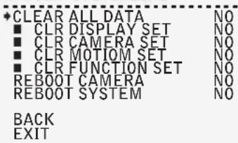
SYSTEM INITIALIZE
| CLEAR ALL DATA | YES / NO |
| Deletes all configuration data such as display, camera, motion setup, etc. | |
| CLR DISPLAY SET | YES / NO |
| Initializes display configuration. | |
| CLR CAMERA SET | YES / NO |
| Initializes camera configuration. | |
| CLR MOTION SET | YES / NO |
| Initializes motion configuration. | |
| CLR FUNCTION SET | YES / NO |
| Deletes preset data, scan data, pattern data, group data, and schedule data. | |
| REBOOT CAMERA | YES / NO |
| Reboots zoom camera module. | |
| REBOOT SYSTEM | YES / NO |
| Reboots speed dome camera. | |
Initial Configuration Table
| Address | ON | |
| Camera ID | OFF | |
| PTZ Information | AUTO | |
| Action Title | AUTO | Display |
| Preset Label | AUTO | |
| Alarm I/O | AUTO | |
| Date/Time | ON | |
| Privacy Zone | Undefined | |
| Preset Lock | OFF | |
| Power Up Action | ON | |
| Auto Flip | ON | |
| Jog Max Speed | 140°/sec | Motion |
| Jog Direction | NORMAL | |
| Freeze In Preset | OFF | |
| Park Action | OFF | |
| Preset 1~255 | Undefined | |
| Auto Pan 1~8 | Undefined | |
| Pattern 1~4 | Undefined | Function |
| Scan 1~8 | Undefined | |
| Schedule 1~7 | Undefined | |
| Focus Mode | AUTO | |
| Digital Zoom | OFF | |
| Image Flip | OFF | |
| Flickerless | OFF | |
| DIS Mode | OFF | |
| Day/Night | DAY | |
| WB Mode | ATW2 | |
| Red Adjust | 0 | |
| Blue Adjust | 0 | |
| Day/Night | NIGHT | |
| WB Mode | OFF | |
| Iris | ALC | |
| Iris Level | 0 | Camera |
| Backlight | OFF | |
| Day/Night | AUTO | |
| Burst | OFF | |
| Brightness | MIDDLE | |
| Dwell Time | 5 SEC | |
| Mask Area | Undefined | |
| Motion | F.FAST | |
| Sens-up | AUTOx4 | |
| DNR | MIDDLE | |
| Zoom Speed | 4 | |
| Detail | 2 | |
| PIP | OFF | |
| Posi/Nega | + | |
| LANGUAGE | ENGLISH | SYSTEM |
| AUTO CAL. | ON |
unit: mm
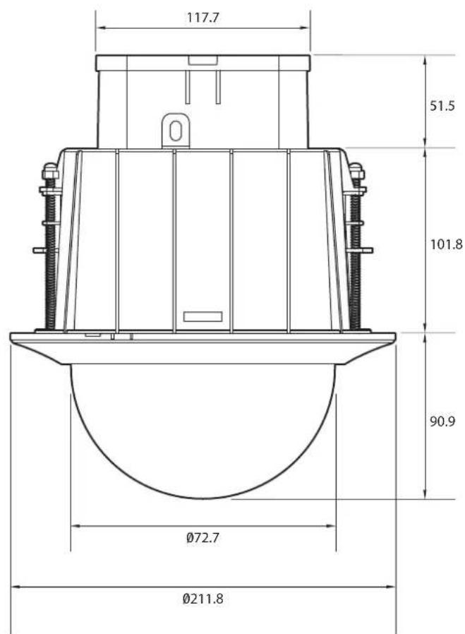
4 Specifications - Specification PTZ37XFM
Camera
| Image Device | 1/4" Interline Transfer CCD |
| Effective Pixel | : 768 (H) x 494 (V), 380K |
| H. Resolution | Color: 560 TV Lines B/W: 680 TV Lines |
| S/N Ratio | 52 dB (AGC Off) |
| Zoom | x37 Optical Zoom & x16 Digital Zoom (Total x592) |
| Focal Length | f = 3.5 (W) ~ 129.5 (T) mm, F1.6 (W) ~ 3.9 (T) |
| Angle of View | H: 55.5° (W) ~ 1.59° (T)V: 42.5° (W) ~ 1.19° (T) |
| Min. Illuminance | 0.7Lux (F1.6, 50IRE) at Color0.07Lux (F1.6, 50IRE) at B/W |
| Shutter Speed | X512 ~1/120,000 |
| Day & Night | Auto / Day / Night (ICR) |
| Focus | Auto / Manual / Semi-Auto |
| Iris | Auto / Manual |
| White Balance | AUTO / AWC / INDOOR / OUTDOOR / Manual (1700 °K ~ 11,000°K) |
| AGC | OFF, LOW, MIDDLE, High Selectable |
| 3D SSNR | Low, Middle, High, Off |
| DIS | On / Off |
| BLC | OFF / BLC / HLC / WDR Selectable |
| WDR | On / Off |
| Other Functions | Frame Freeze Function, System Image Flip by Installation Type |
Pan/Tilt
| Pan Range | 360° (Endless) |
| Tilt Range | 0° ~ 180° (Auto-Flip ON) • 0° ~ 90° (Auto-Flip OFF) |
| Pan/Tilt Speed | Preset: 360° |
| Scan: 1° ~ 180°/sec. | |
| Manual: 0.05° ~ 200°/sec. (Zoom Proportional) | |
| Preset | 127 Presets with Labels / Independent Camera Setup |
| Pattern | 4 Patterns |
| Scan | 8 Scans |
| Group | 8 Groups (Maximum 20 Entries per Group) |
| Schedule | 7 Rules (Condition: Day, Time → Action: Preset, Scan, Group, Pattern) |
| Other Functions | Image Auto Flip, Auto Parking, Power-Up Action, etc. |
General
| Video Out | CVBS: 1.0 V p-p / 75Ω |
| Communication | RS-485 |
| Protocol | Auto, Pelco-D/P, Samsung, Panasonic, GE (Kalatel), AD Selectable |
| Privacy Zone | 8 Zones |
| Sensor In/Out | 8 Input / 4 Relay Output |
| OSD | Available, Supports 7 Languages:ENGLISH / ESPAÑOL / FRANÇAIS / DEUTSCH / ITALIANO / РУССКИЙ / PORTUGUÊS |
| Power | AC 24V: 24 W, 1A |
| Approvals | FCC, CE, RoHS |
| Material | Body: Plastic • Clear Dome: Polycarbonate |
| Weight | 12.8 lbs. (5.8Kg) |
| Operating Temp. | -10° ~ 50° C (14° ~ 122° F) |
| Power Requirements | AC24V |
| Power Consumption | Heater OFF: 24W, 1000mA | Heater ON: 57W, 2400mA |
Warranty Information
Digital Watchdog (referred to as the "Warrantor") warrants the Digital Watchdog camera against defects in materials or workmanship as follows:
LABOR: For the initial two (2) years from the original purchase date, if the camera is determined to be defective, the Warrantor will display or replace the unit with a new or refurbished product at its option at no charge.
PARTS: In addition, the Warrantor will supply replacement parts for the initial two (2) years.
To obtain warranty or out-of-warranty service, please contact a Technical Support Representative at 1-866-446-3595 Monday through Friday from 8:30AM to 8:00PM Eastern Standard Time.
A purchase receipt or other proof of the original purchase date is required before warranty service is rendered. This warranty only covers failures due to defects in materials and workmanship which arise during normal use. The warranty does not cover damage which occurs in shipment or failures which are caused by products not supplied by the Warrantor or failures which result from accident, misuse, abuse, neglect, mishandling, misapplication, alteration, modification, faulty installation, set-up adjustments, improper antenna, inadequate signal pickup, maladjustment of consumer controls, improper operation, power line surge, improper voltage supply, lightning damage, rental use of the product or service by anyone other than an authorized repair facility or damage that is attributable to acts of God.
Limits and Exclusions
There are no express warranties except as listed above. The warrantor will not be liable for incidental or consequential damages (including without limitation or damage to recording media) resulting from the use of these products or arising out of any breach of the warranty. All express and implied warranties, including the warranties of merchantability and fitness for particular purpose, are limited to the applicable warranty period set forth above.
Some states do not allow the exclusion or limitation of incidental or consequential damages or limitations on how long an implied warranty lasts, so the exclusions or limitations listed above may not apply to you. This warranty gives you specific legal rights, and you may also have other rights that vary from state-to-state.
If the problem is not handled to your satisfaction, then write to the Address listed on the next page.
Service calls which do not involve defective materials or workmanship as determined by the Warrantor, in its sole discretion, are not covered. Costs of such service calls are the responsibility of the purchaser.
DW DIGITAL WATCHDOG®
Complete Surveillance Solutions
5436 W Crenshaw St. Tampa, FL 33634
Tel: 866-446-3595 / 813-888-9555
Fax:813-888-9262
www.Digital-Watchdog.com
technicalsupport@dwcc.tv
Technical Support Hours: Monday-Friday
9:00am to 8:00pm Eastern Time

natural_image
Symbol of a trash bin crossed with a diagonal line, representing no waste or discharge (no text or labels)Correct Disposal of This Product (Waste Electrical & Electronic Equipment)
(Applicable in the European Union and other European countries with separate collection systems)
This marking on the product, accessories or literature indicates that the product and its electronic accessories (e.g. charger, headset, USB cable) should not be disposed of with other household waste at the end of their working life. To prevent possible harm to the environment or human health from uncontrolled waste disposal, please separate these items from other types of waste and recycle them responsibly to promote the sustainable reuse of material resources.
Household users should contact either the retailer where they purchased this product, or their local government office, for details of where and how they can take these items for environmentally safe recycling.
Business users should contact their supplier and check the terms and conditions of the purchase contract.
This product and its electronic accessories should not be mixed with other commercial wastes for disposal.
FCC
This equipment has been tested and found to comply with the limits for a Class A digital device, pursuant to part 15 of the FCC Rules.
These limits are designed to provide reasonable protection against harmful interference when the equipment is operated in a commercial environment.
This equipment generates, uses, and can radiate radio frequency energy and, if not installed and used in accordance with the instruction manual, may cause harmful interference to radio communications. Operation of this equipment in a residential area is likely to cause harmful interference in which case the user will be required to correct the interference at his own expense.
- Super Speed Dome
- PTZ37XFM PTZ37X In-Ceiling Flush Mount
- CAUTION
- CAUTION:
- WarningPrecaution
- WARNING
- Safety Information
- PRECAUTION
- Operating
- Handling
- Installation and Storage
- Introduction - Product & Accessories
- Installation - DIP Switch Setup
- Communication Protocol Setup
- Communication Baud Rate Setup
- RS-485 Termination Resistor
- Camera ID Setup
- Installation - Installation
- CONNECT THE WIRES AND TERMINAL BLOCKS
- CLOSE THE JUNCTION BOX COVER
- INSERT THE IN-CEILING HOUSING
- INSERT THE IN-CEILING HOUSING
- INSERT THE PTZ MECHANISM
- Installation - Cabling
- ① RS-485 Communication (DVR/Keyboard)
- Power Connection
- Video Output
- Alarm Output
- Sensor Input
- OSD - Check Points Before Operation
- Check Points Before Operation
- Preset and Pattern Function Pre-Check
- Auto Calibration
- Open OSD Menu
- OSD - Functions
- Preset
- Set Preset
- Run Preset
- Delete Preset
- Scan
- Set Scan
- Run Scan
- Delete Scan
- Pattern
- Set Pattern
- Run Pattern
- Delete Pattern
- Group
- Set Group
- Run Group
- Delete Group
- Schedule
- OSD - OSD Display of Main Screen
- Preset Label
- Camera ID\_Top
- Camera ID\_Bottom
- Date / Time
- Image Flip
- Address
- Action Title
- Alarm I/O Information
- Compass Direction
- Zoom Magnification
- Tilt Angle in Degree
- Pan Angle in Degree
- OSD - General Rules of Menu Operation
- OSD - ROOT MENU > SYSTEM INFORMATION
- ROOT MENU
- SYSTEM INFORMATION
- OSD - DISPLAY SETUP > CAMERA ID
- DISPLAY SETUP
- CAMERA ID
- CAMERA ID - Complete Editing
- OSD - DISPLAY SETUP > PRIVACY ZONE
- EDIT MASK - Move to Target Position
- EDIT MASK - Adjust Mask Size
- PRIVACY ZONE
- OSD - MOTION SETUP
- MOTION SETUP
- PWR UP ACTION ON / OFF /
- AUTO FLIP ON/OFF
- JOG MAX SPEED 2/SEC \~ 200/SEC
- JOG DIRECTION INVERSE / NORMAL
- PARKING ACTION SETUP
- PARK ENABLE ON/OFF
- WAIT TIME 00:00:05 \~ 04:00:00
- PARKING ACTION HOME / PRESET 1\~128 / SCAN 1\~8 /
- PATTERN 1\~4 / GROUP 1\~8
- ALARM INPUT SETUP
- OSD - FUNCTION SETUP > PRESET SETUP
- FUNCTION SETUP
- PRESET SETUP - Undefined
- EDIT SCENE
- PRESET SETUP
- CAM ADJUST
- GENERAL / SPECIAL
- ALARM OUT
- LABEL
- LABEL – Complete Editing
- CAM ADJUST
- OSD - FUNCTION SETUP > SCAN SETUP
- SCAN SETUP
- OSD - FUNCTION SETUP > PATTERN SETUP
- PATTERN SETUP
- EDIT PATTERN - Select the Position
- EDIT PATTERN - Records
- OSD - FUNCTION SETUP > GROUP SETUP
- GROUP SETUP SCREEN
- EDIT GROUP - Initial Screen
- EDIT GROUP – Select Function Sequence
- EDIT GROUP - Assign Function
- EDIT GROUP - Selects Function Sequence
- EDIT GROUP - Saves the Setting
- OSD - FUNCTION SETUP > SCHEDULE SETUP
- SCHEDULE SETUP SCREEN
- 5 SCHEDULE SETUP - Assign Value
- EXAMPLE:
- OSD - CAMERA SETUP > WB SETUP
- ZOOM CAMERA SETUP
- FOCUS MODE
- AUTO / MANUAL / SEMIAUTO
- DIGITAL ZOOM
- ON / OFF
- IMAGE FLIP
- FLICKERLESS
- DIS
- WB SETUP - DAY
- DAY/NIGHT
- DAY / NIGHT
- WB MODE
- ATW1 / ATW2 / AWC / 3200K / 5600K / OFF
- RED/BLUE ADJUST
- -32 \~ +32
- R/B - GAIN
- 0\~1000
- WB SETUP - NIGHT
- BRIGHTNESS
- LOW / MIDDLE / HIGH
- OSD - CAMERA SETUP > AE SETUP
- AE SETUP
- AE SETUP - IRIS > ALC
- BLC AREA
- DAY/NIGHT
- AE SETUP - IRIS > ALC > BACKLIGHT > WDR
- OSD - CAMERA SETUP > SPECIAL
- SPECIAL
- OSD - SYSTEM SETUP
- SYSTEM SETUP
- LANGUAGE
- AUTO CAL. ON/OFF
- RELAY TYPE SETUP
- EDIT PASSWORD
- 5
- 6
- SET HOME POSITION
- Set Home Position?
- SET NORTH DIRECTION
- Specifications - Specification PTZ37XFM
- Warranty Information
- Limits and Exclusions
- DW DIGITAL WATCHDOG®
- Correct Disposal of This Product (Waste Electrical & Electronic Equipment)
- FCC
Brand : Digital Watchdog
Model : Star-Light DWC-PTZ37XFM
Category : Security Camera