L700CART - Unspecified Sedona - Free user manual and instructions
Find the device manual for free L700CART Sedona in PDF.

User questions about L700CART Sedona
0 question about this device. Answer the ones you know or ask your own.
Ask a new question about this device
Download the instructions for your Unspecified in PDF format for free! Find your manual L700CART - Sedona and take your electronic device back in hand. On this page are published all the documents necessary for the use of your device. L700CART by Sedona.
USER MANUAL L700CART Sedona
Lynx Freestanding Cart Model L400CART, L500CART & L600CART
Introducon:
Your Freestanding Cart comes with all of the components necessary to assemble a cart for the SEDONA Series of Lynx Grills.
The SEDONA CART series is comprised of 8 sub assemblies:
- Back Panel Assembly
- Right Side Panel Assembly with Shelf
- Le Side Panel Assembly with Shelf
- Base Assembly with Wheels
- Inner Shelf Assembly
- Cross Brace Assembly
- Right Door
- Le Door
In addition there are 14 screws (1/4 -20 x ½) to assemble the cart and grill and 4 screws with nuts (#8-32 x 3/8) to each the transformer assembly supplied with the Grill.
Step 1.
Aer opening and identifying the components, select the back panel assembly and either the right or le side panel assembly. Orient the parts as shown in the illustraon for step 1.
Note that these parts are upside down with the shelves at the oor. Hook the right or le side to the back into the four keyways located on the edge. When aached all four keyways should be engaged and the back and side ush to the top. Repeat this step for the opposite side panel.
Step 2.
With the cart oriented upside down, locate the 4 - #8 screws and nuts and mount the electrical transformer to the access plate shown in the illustraon for this step. It may be done at the end of the assembly but is somewhat easier to access at this stage.
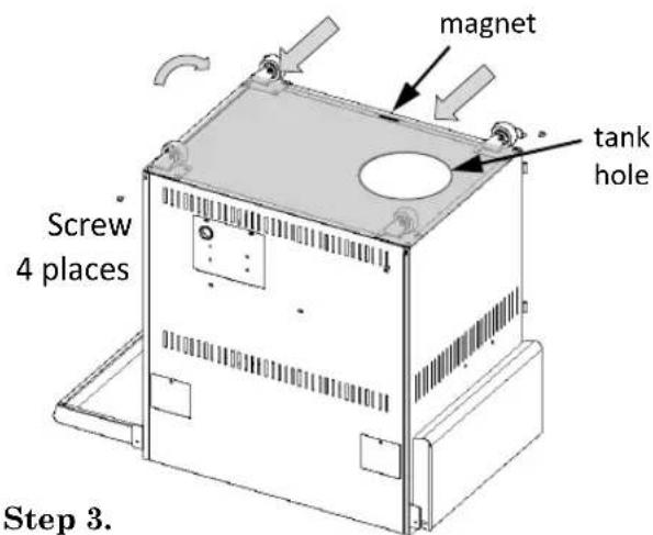
Step 3.
Refer to the gure for step 3 and insert the base assembly into the cavity at the back corners of the cabinet. Check that the tank hole is posioned as shown and the magnet is located on the open side. Splay the two sides out slightly and enclose them over the front of the base. The sides and back have pockets that t over the casters for clearance. Use 4 of the 14 -20 x 12 screw at each corner to lock the assembly in place.

natural_image
Isometric line drawing of a mechanical or architectural component with no visible text, numbers, or symbols.Step 1.

text_image
Access Plate Step 3Step 2.
text_image
magnet tank hole Screw 4 places Step 3.Step 4.
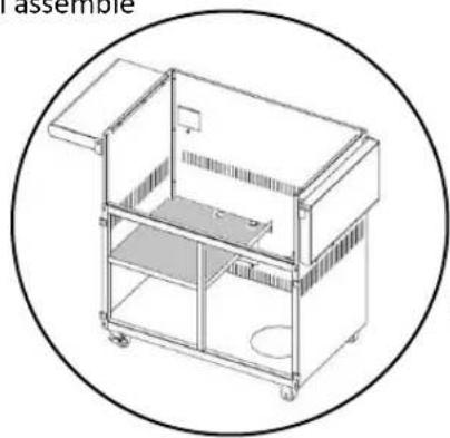
To begin step 4 turn the cabinet upright to secure the Inner Shelf Assembly. The L400 and L500 shelf will only assemble as shown at the right with the electrical hole to the rear and the screws mounng at the back and le side. The shelf is not only useful but necessary for the proper stability of the cart. DO NOT omit the inner shelf or any part in these instrucons.
The inner shelf is secured by 4 of the 14 -20 x 12 screws. Two through the back and two through the le side.
The L600 shelf as shown here will assemble the same as above.
Step 4. L600
natural_image
Line drawing of a multi-tiered industrial machine or storage unit enclosed in a circular frame (no text or symbols)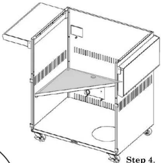
natural_image
Line drawing of a mechanical device with wheels and a triangular component, labeled 'Step 4.' (no text or symbols on the diagram itself)Step 4. L400 L500

natural_image
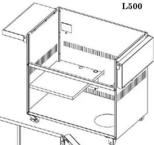
Technical line drawing of a mechanical cart or enclosure with wheels and internal structure (no text or symbols)Step 5. L400 L500
Step 5.
Step 5 is the last assembly on the L400/L500 cart before installing the Grill to the cart. The cross brace ts into recesses located at the front edge of the cart above the hinge brackets. Orient the brace with the center magnet facing forward and posioned such that the magnet is higher than center rather than lower. Install the brace from the backside of the angles and align the nutcerts at each end with the holes provided for the screws. The brace is secured by 2 of the 14 -20 x 12 screws.
The L600 door frame is aached along with the cross brace. Support the cross brace from the backside of the front angles. Align the nutcerts at each end with the holes provided for the screws. Posion the door frame over the nutcerts and cross brace, and secure them both with the 14 -20 x 12 screws.
natural_image
Technical line drawing of a mechanical device labeled L500, showing internal components and mounting brackets (no text or symbols beyond label)Step 5. L600

natural_image
Technical line drawing of a three-panel cabinet or enclosure structure (no text or symbols)Step 6.
With assistance, remove all packing materials from the grill. Also remove the grates and warming racks to lighten the assembly. The grill will be placed onto the cart as illustrated in this step. The back edge will engage rst and the front will slide down into posion unl horizontal.
Using two people – with gloves - grasp the front and side of the Grill at points A and B. Place the unit on the cart and lower it slowly unl horizontal.
Do not grip grill by the control knobs as damage may occur
Drop the door hinge pins into the corresponding door hinge on the frame.

natural_image
Technical diagram of a structural frame assembly with an arrow indicating direction (no text or symbols present)
text_image
A B StepStep 6.
Step 7.
Four screws remain in the package for assembly. To secure the grill to the cart locate 4 screws at the inside corners of the rebox. Remove and discard the 4 screws at these locaons. Replace them one at a me with the 14 - 20 × 12 screws from the kit.
The le and right hand doors now assemble to the c art as shown.
Refer to the installaon manual provided with the grill for the proper electrical and gas connecons.

text_image
Technical diagram of an electric stove with numbered components and a magnified inset showing internal structure.Step 5. L600