CMS441 - Unspecified Chief - Free user manual and instructions
Find the device manual for free CMS441 Chief in PDF.


| Product Type | Ceiling mount enclosure system for projectors and AV equipment |
| Model | CMS441 |
| Brand | Chief (Milestone AV Technologies) |
| Compatible Models | CMS491, CMS492, CMS491C, CMS492C |
| Maximum Total Weight Capacity | 100 lbs (45 kg) |
| Maximum Shelf Weight Capacity | 25 lbs (22 kg) per shelf (CMSUNV1/CMSUNV2) |
| Maximum Extension Column Weight Capacity | 50 lbs (22 kg) (for CMS491C/CMS492C) |
| Ceiling Type | Suspended ceiling with 2' x 2' tiles |
| Support System | WireVice cable hanger system (4 cables) |
| Electrical Outlet Support | Single or double electrical receptacle (15A minimum) |
| Material | Steel (powder-coated) |
| Dimensions (CMS491) | 1x2 ceiling tile opening (19-1/8" x 10-3/8" tile cutout) |
| Dimensions (CMS492) | 2x2 ceiling tile opening (19-1/8" x 22-1/8" tile cutout) |
| Extension Column Thread | 1-1/2" NPT or NPSM (ANSI/ASME B1.20.1 Schedule 40, 0.154" min wall) |
| Indoor Use Only | Yes |
| Safety Standards | Complies with National Electrical Code (ANSI/NFPA 70) and Canadian Electrical Code (CSA C22.1) |
| Included Accessories | Mounting hardware, cable locks, screws, electrical plate |
| Optional Accessories | Extension column, component shelves (CMSUNV1, CMSUNV2), security screw |
| Installation Tools Required | Phillips screwdriver, flathead screwdriver, hammer, drill, claw hammer, pencil |
| Product Series | CMS Series |
| Warranty | Standard Chief warranty (refer to manual) |
Frequently Asked Questions - CMS441 Chief
User questions about CMS441 Chief
0 question about this device. Answer the ones you know or ask your own.
Ask a new question about this device
Download the instructions for your Unspecified in PDF format for free! Find your manual CMS441 - Chief and take your electronic device back in hand. On this page are published all the documents necessary for the use of your device. CMS441 by Chief.
USER MANUAL CMS441 Chief
INSTALLATION INSTRUCTIONS

natural_image
Technical line drawings of two computer case compartments labeled CMS491 and CMS492, showing internal components and mounting points (no text or symbols beyond labels)Ceiling Tile Storage Kits
DISCLAIMER
Milestone AV Technologies and its affiliated corporations and subsidiaries (collectively “Milestone”), intend to make this manual accurate and complete. However, Milestone makes no claim that the information contained herein covers all details, conditions or variations, nor does it provide for every possible contingency in connection with the installation or use of this product. The information contained in this document is subject to change without notice or obligation of any kind. Milestone makes no representation of warranty, expressed or implied, regarding the information contained herein. Milestone assumes no responsibility for accuracy, completeness or sufficiency of the information contained in this document.
Chief® is a registered trademark of Milestone AV Technologies. All rights reserved.

IMPORTANT SAFETY INSTRUCTIONS

WARNING: A WARNING alerts you to the possibility of serious injury or death if you do not follow the instructions.

CAUTION: A CAUTION alerts you to the possibility of damage or destruction of equipment if you do not follow the corresponding instructions.

WARNING: Failure to read, thoroughly understand, and follow all instructions can result in serious personal injury, damage to equipment, or voiding of factory warranty! It is the installer's responsibility to make sure all components are properly assembled and installed using the instructions provided.

WARNING: Failure to provide adequate structural strength for this accessory can result in serious personal injury or damage to equipment! It is the installer's responsibility to make sure the structure to which this accessory is attached can support five times the combined weight of all equipment. Reinforce the structure as required before installing the component.

WARNING: Exceeding the weight capacity can result in serious personal injury or damage to equipment! It is the installer's responsibility to make sure the combined weight of:
- all components located in the complete accessory does not exceed 100 lbs (45 kg).
- all components attached to the CMS491/CMS492 Series component shelf may not exceed 25 lbs (22 kg) per shelf;
- all components attached to the extension column, (CMS491C/CMS492C models only) does not exceed 50 lbs (22 kg).

WARNING: Use this mounting system only for its intended use as described in these instructions. Do not use attachments not recommended by the manufacturer.

WARNING: For indoor use only.

WARNING: Never operate this mounting system if it is damaged. Return the mounting system to a service center for examination and repair.
IMPORTANT ! : The CMS491/492 has been designed to be mounted recessed into a suspended ceiling secured by a WireVice system.
IMPORTANT ! : The CMS491/492 has been designed to support a single electrical receptacle or a double receptacle.
NOTE: It is the installer's responsibility to ensure that the enclosure is bonded to the ground in the switch box, in accordance with the National Electric Code, ANSI/NFPA 70 or Canadian Electrical Code, CSA C22.1. A green grounding screw is provided in the enclosure for the purpose, if required.
NOTE: Spacings - To ensure safe operation of the equipment installed in the enclosure, per National Electric Code, ANSI/NFPA 70, a minimum separation between power cords and signal or communication cables may be required.
NOTE: This Cabinet System is for use with Listed ITE or Audio/Video equipment only.
NOTE: When selecting a Listed 120 Vac Receptacle for use as the main power source for the CMS Series boxes (to power the A/V equipment), make sure that AC Receptacle is rated at least 15A and it is used in the building's AC branch circuit that is connected to a circuit breaker rated at least 15A. Do not connect more than 12A from the 15A Receptacle, or 16A from the 20A Receptacle.
In the U.S., the equipment shall be installed per the applicable requirements of the National Electrical Code, ANSI/NFPA 70.
In Canada, the equipment shall be installed per the applicable requirements of the Canadian Electrical Code, CSA C22.1.
NOTE: The CMS491/492 Series consists of:
CMS491 1x2 Standard Ceiling Box
• CMS491C 1x2 Ceiling Box with Column Drop
CMS492 2x2 Standard Ceiling Box
CMS492C 2x2 Ceiling Box with Column Drop
NOTE: The CMS491C and CMS492C each accommodate a Listed Chief CMS Series extension column (not included).
--SAVE THESE INSTRUCTIONS--
DIMENSIONS
CMS491
![1.38 [34.9] DOOR DROP 1.13 [28.6] 19.25 [489.0] TILE INSERTION SPACE 12.97 [329.5] 8.67 [220.1] 19.25 TILE WIDTH 0-0.25 [6.4] SIDE TRIM EXTENSION (MIN-MAX) DEPTH ADJUST ELECTRICAL INSTALL PLATE SPACE FOR A SINGLE GANG OUTLET1. DUAL GANG OUTLET2. PASS THROUGH FOR DUAL GANG3. OUTLET ATTACHED TO 1/2" CONDUIT 23.67 [601.1] MOUNTING WIDTH 2.25 [57.2] BOTTOM SHELF SPACE 7.58 [192.4] AVAILABLE STORAGE HEIGHT SECTION B-B 1.91 [48.4] TOP SHELF SPACE DETAIL A SCALE 1:2 ∅ 0.88 [22.2] TRADE CONDUIT SIZE 1/2" METRIC CONDUIT SIZE 16mm ∅ 1.38 [34.9] TRADE CONDUIT SIZE 1" METRIC CONDUIT SIZE 27mm ∅ 1.73 [44.0] TRADE CONDUIT SIZE 1-1/4" METRIC CONDUIT SIZE 35mm](/content/2026/06/1203854/images/d7ce13119db39197f0f5aa097856cb4b8ecade964a984747ee23fc010c8fd9b2.jpg)
CMS491C
![1.38 [34.9] DOOR DROP 1.13 [28.6] 19.25 [489.0] TILE WIDTH ELECTRICAL INSTALL PLATE SPACE FOR A SINGLE GANG OUTLET1. DUAL GANG OUTLET2. 1 REMOVABLE SHELF INCLUDED 2 SPACES TOTAL AVAILABLE 2.59 [65.9] PIPE DROP CENTER SIDE TRIM EXTENSION 12.97 [329.5] 8.67 [220.1] 13.63 [346.1] PIPE DROP TRAVEL 5.02 [127.5] PIPE DROP MIN CENTER 23.67 [601.1] MOUNTING WIDTH 2.25 [57.2] BOTTOM SHELF SPACE 7.61 [193.3] AVAILABLE STORAGE HEIGHT SECTION B-B 1.91 [48.4] TOP SHELF SPACE DETAIL A SCALE 1:2 Φ0.88 [22.2] TRADE CONDUIT SIZE 1/2" METRIC CONDUIT SIZE 16mm Φ1.38[34.9] TRADE CONDUIT SIZE 1" METRIC CONDUIT SIZE 27mm Φ1.73 [44.0] TRADE CONDUIT SIZE 1-1/4" METRIC CONDUIT SIZE 35mm](/content/2026/06/1203854/images/c0b3e85a3aa560851a49344ab8718678b8e4f5a880ca551508374379888272fa.jpg)
DIMENSIONS
CMS492
![0.25 [6.4] 19.25 [489.0] TILE INSERTION SPACE 23.69 [601.7] MOUNTING LENGTH 24.97 [634.3] B 1 REMOVABLE SHELF INCLUDED 2 SPACES TOTAL AVAILABLE 23.67 [601.1] MOUNTING WIDTH 2.25 [57.2] BOTTOM SHELF SPACE 8.67 [220.1] ELECTRICAL INSTALL PLATE SPACE FOR A SINGLE GANG OUTLET1. DUAL GANG OUTLET2. PASS THROUGH FOR DUAL GANG3. OUTLET ATTACHED TO 1/2" CONDUIT 7.60 [192.9] AVAILABLE STORAGE HEIGHT SECTION B-B 1.91 [48.4] TOP SHELF SPACE DETAIL A SCALE 1:2 Φ0.88 [22.2] TRADE CONDUIT SIZE 1/2" METRIC CONDUIT SIZE 16mm Φ1.38 [34.9] TRADE CONDUIT SIZE 1" METRIC CONDUIT SIZE 27mm Φ1.73 [44.0] TRADE CONDUIT SIZE 1-1/4" METRIC CONDUIT SIZE 35mm](/content/2026/06/1203854/images/e6061b904ff2f9c8b9e4fc9c7271363904c2ae87036067d020d2d46a59c5593f.jpg)
CMS492C
![23.67 [601.1] 1.38 [34.9] DOOR DROP 1.13 [28.6] 19.25 [489.0] TILE INSERTION SPACE 5.02 [127.5] 13.63 [346.1] PIPE DROP TRAVEL ELECTRICAL INSTALL PLATE SPACE FOR A SINGLE GANG OUTLET1. DUAL GANG OUTLET2. 23.69 [601.7] MOUNTING LENGTH ELECTRICAL INSTALL PLATE SPACE FOR A SINGLE GANG OUTLET1. DUAL GANG OUTLET2. PASS THROUGH FOR DUAL GANG3. OUTLET ATTACHED TO 1/2" CONDUIT 24.97 [634.3] 8.67 [220.1] 1 REMOVABLE SHELF INCLUDED 2 SPACES TOTAL AVAILABLE 9.40 [238.9] PIPE DROP TRAVEL 2.69 [68.3] PIPE DROP MIN CENTER 23.67 [601.1] MOUNTING WIDTH 2.25 [57.2] BOTTOM SHELF SPACE 7.60 [192.9] AVAILABLE STORAGE HEIGHT SECTION B B 1.91 [48.4] TOP SHELF SPACE DETAIL A SCALE 1 : 2 Ø 0.88 [22.2] TRADE CONDUIT SIZE 1/2" METRIC CONDUIT SIZE 16mm Ø 1.38 [34.9] TRADE CONDUIT SIZE 1" METRIC CONDUIT SIZE 27mm Ø 1.73 [44.0] TRADE CONDUIT SIZE 1-1/4" METRIC CONDUIT SIZE 35mm](/content/2026/06/1203854/images/a787a8eb9321dd6ab54bfc52284635852f0b535246bce6c14f63fc5b7138412f.jpg)
LEGEND
 | Tighten Fastener |
| Apretar elemento de fijación | |
| Befestigungsteil festziehen | |
| Apertar fixador | |
| Serrare il fissaggio | |
| Bevestiging vastdraaien | |
| Serrez les fixations | |
 | Loosen Fastener |
| Aflojar elemento de fijación | |
| Befestigungsteil lösen | |
| Desapertar fixador | |
| Allentare il fissaggio | |
| Bevestiging losdraaien | |
| Desserrez les fixations | |
 | Phillips Screwdriver |
| Destornillador Phillips | |
| Kreuzschlitzschraubendreher | |
| Chave de fendas Phillips | |
| Cacciavite a stella | |
| Kruiskopschroevendraaier | |
| Tournevis à pointe cruciforme | |
 | Flathead Screwdriver |
 | By Hand |
| A mano | |
| Von Hand | |
| Com a mao | |
| A mano | |
| Met de hand | |
| A la main | |
 | Target of Projector |
| Punto de enfoque del proyector | |
| Ziel des Projektors | |
| Mira do projector | |
| Punto di proiezione | |
| Doel van de projector | |
| Cible du projecteur |


TOOLS REQUIRED FOR INSTALLATION

PARTS INCLUDED

OPTIONAL PARTS PER CUSTOM CONFIGURATION (NOT INCLUDED)

PREPARING FOR INSTALLATION
Installation Requirements
The CMS491/492 has been designed to be mounted recessed into a suspended ceiling consisting of 2' × 2' ceiling tiles and secured by a Wire Vice system.
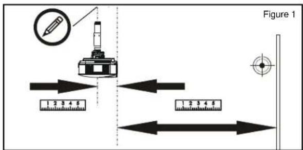
NOTE: Regarding location selection for models CMS491C/ CMS492C: The design of the projector mount plate/ceiling AV enclosure system does not require pre-measurement of the mount location other than choosing the tile placement of the enclosure. If you are pre-measuring for projector mount location be sure to consider the items below.
- Dimensional offset of the display/projector relative to column (due to mount and interface).
- For projectors: any recommended dimensions of projector relative to target (see installation instructions included with the projector).
Preparing Framework
① Remove one 2' x 2' tile from ceiling.
② Move/reconfigure existing wires or conduit if obstructing location.
③ Pre-install cable hanger system.
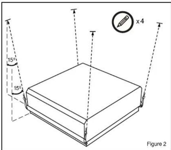
Examine ceiling structure (solid concrete, wood or steel truss) above kit to be installed to identify four support cable anchor locations. Each location should be approximately 15° outside of support holes in kit assembly. Mark locations with a pencil.
SUPPORT CABLE INSTALLATION

WARNING: Failure to provide adequate structural strength for this component can result in serious personal injury or damage to equipment! It is the installer's responsibility to make sure the structure to which this component is attached can support five times the combined weight of all equipment. Reinforce the structure as required before installing the component.
Solid Concrete Ceiling Structure

WARNING: Anchors must be installed into structurally sound solid concrete with a minimum thickness of 1.75" (44.5mm) or greater. Installation into hollow concrete block, mortar, or concrete that exhibits cracking, spalling, or other defects may result in failure of anchor and serious personal injury or damage to equipment!
① Drill 1/4" diameter x 1-3/8" deep pilot hole at each marked cable anchor support location (See Figure 3). Ensure hole is at least 2-1/2" from nearest concrete edge. Remove debris from hole.

② Tap anchor (K) into each hole to a depth of at least 1" (25mm) (See Figure 3).

WARNING: Failure to properly set anchor may result in failure of anchor and serious personal injury or damage to equipment!
③ Using claw portion of hammer, set each anchor (K) by pulling it out of hole approximately 1/4" (6.4mm). (See Figure 3)
④ Insert portion of manufactured loop on cable (N) through hole in anchor (K) (See Figure 3). Insert end of cable (N) through loop. Repeat for 3 remaining support locations.
Wood Ceiling Structure

WARNING: Anchors must be installed into wood with a minimum thickness of 1-1/2" (38.1 mm) or greater.
① Drill 5/32" diameter x 2" deep hole at each marked cable anchor support location (See Figure 4). Remove debris from hole.
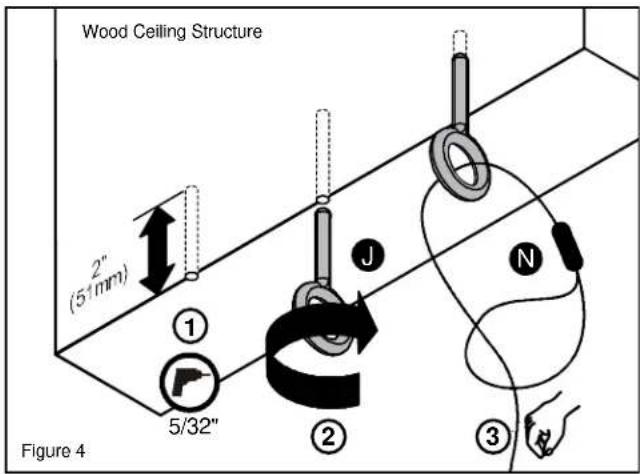
② Fully thread eye lag (J) into each hole (See Figure 4).
③ Route end of cable (N) through eye lag (J) and then through cable loop (See Figure 4). Repeat for 3 remaining support locations.
Steel Truss Ceiling Structure
① Route end of cable (N) over truss at marked cable anchor support location and then through cable loop. (See Figure 5) Repeat for 3 remaining support locations.

Installing Electrical Box and Outlets
Determine desired location for installing electrical outlets within box.

Box Sidewall Electrical Install Option
① Remove two-piece electrical plate from box sidewall. Save screws for re-attachment. Break away inner portions of plate halves. Attach a pair of outlets to an electrical box, then attach plate halves to outlet box configuration.

CAUTION: Injury may occur on sharp edges. Carefully discard the removable tabs.
② Insert tab on bottom edge of electrical plate into opening on side wall of box. Rotate to flatten against box, and affix plate to box by re-using screws removed in Step 1.

natural_image
Hand installing or adjusting a metal bracket component, showing internal circular holes and mounting holes (no text or symbols)Projector Mount Plate Electrical Install Option
① Remove attached electrical plate from underside of projector mount plate. Save nuts for reinstall.
○ Remove break away panel from projector mount plate.2

natural_image
Line drawing of a hand using a tool to cut or mark a piece on a flat surface, labeled 'Figure 9' (no text or symbols on the diagram itself)
CAUTION: Avoid sharp edges.
③ Attach a pair of outlets to an electrical box, then attach accompanying one-piece electrical plate to outlet box configuration.

natural_image
Technical line drawing of a wall-mounted electrical socket assembly (no text or symbols)④ If outlet box configuration is attached to wiring/conduit prior to box attachment, remove two-piece electrical plate from box sidewall, feed configuration through large opening. Then re-attach two-piece plate to close around conduit.

natural_image
Technical line drawing of a mechanical assembly with a coiled spring and mounting base (no text or symbols)⑤ Attach complete outlet box configuration to projector mount plate as shown below in figure 12. Secure by re-attaching nuts removed in Step 1.

natural_image
Illustration of a hand using a tool to cut a die into a tray, labeled 'Figure 12' (no text on diagram itself)Cleat adjustment for various tile heights
① Loosen screws along side cleat, adjust and retighten as needed to accommodate for tile height.

NOTE: Remove the cleat entirely to allow the enclosure to be mounted closer to the tile grid frame.
Placing CMS491/492 into Ceiling Structure
① Carefully insert box through opening. Note angled back edges design which allow box to fit through 2' x 2' opening.

② Rotate and drop box to gently rest into place onto drop ceiling framework.

natural_image
Technical line drawing of a mechanical assembly with no visible text or symbolsInstalling Cable to Box Frame
① Remove adjacent ceiling tiles as needed to access cable attachment locations.

natural_image
Illustration of a person installing or adjusting a ceiling-mounted device (no text or symbols visible)② Attach cables as shown (figure 17) using cable locks (L) to secure cable, adjusted to proper length - allowing box to be level, and NOT RESTING ON CEILING FRAMEWORK.


WARNING: Not properly supporting box with cable hanger system may lead to serious injury or death.

CAUTION: Failure to properly tension cables (N) may result in damage to ceiling tile framework.
③ Thread each cable (N) completely through cable lock (L) corresponding hole in corner of CMS491/492 frame, and completely through opposite side of cable lock (L) (see figure 17).
④ Adjust cable tension until CMS491/492 frame is supported entirely and evenly by all four support cables, but not so tight as to distort ceiling tile framework.
⑤ Secure CMS491/492 assembly in place by feeding #10-24 x 5/8 pan head tapping screws (G) through holes as shown and tighten until secure against ceiling tile framing (2 screws each on opposite sides of the assembly).

Adding Components
NOTE: The CMS491/CMS492 box is designed for attaching a component shelf at two different heights. The following instructions refer to installing the Listed accessories CMSUNV1 and CMSUNV2.

WARNING: Exceeding the weight capacity can result in serious personal injury or damage to equipment! It is the installer's responsibility to make sure the weight of all components attached to the CMS491/CMS492 Series component shelf, does not exceed 25 lbs (22 kg) per shelf.
① Attach component to shelf prior to install. Component may be attached either on top of shelf or below shelf. Attach components per component manufacturer recommended method(s).

② Attach one #10-24 thumb nut (l) to each threaded post.
③ Position shelf (with component attached) into box and hook four corner slots onto the posts of the shelf supports.

natural_image
Illustration of hands installing a window frame on a metal panel, with an inset showing a mechanical clamp (no text or symbols)④ Hand tighten nuts (I) to secure shelf in place.
Finish Install Site
① Pre-cut a ceiling tile to fit inside the drop panel framework
SIZE:
CMS491: 19 1/8" x 10 3/8"
CMS492: 19 1/8" x 22 1/8"
NOTE: If installing models CMS491C/492C cut ceiling tile to fill gaps around mounting plate. Install tile trim (P) on edges of tile that touch mounting plate, and fold trim tabs over tile. (see Figure 21). Install tile with trim attached AFTER installing projector mount plate.
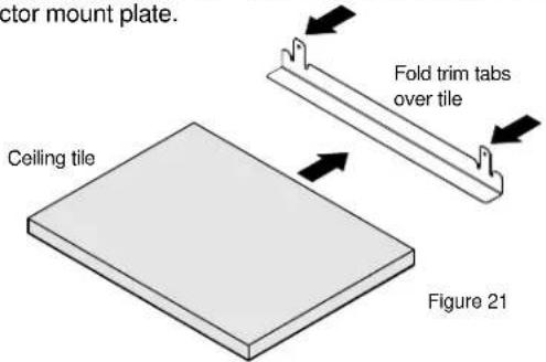
② Finish frame assembly by opening four latches in door panel dropping panel down. Slide tile (cut to size) into location.

natural_image
Line drawing of a device with an open lid and internal components, labeled as Figure 22 (no text or symbols on the diagram itself)③ Push panel assembly back into place and rotate latches to lock position.
Projector Mount Plate and Extension Column Installation
NOTE: The following instructions refer to installing Models CMS491C and CMS492C, or installing the Listed accessories CMS441 and CMS442 into Models CMS491 and CMS492, respectively.
OPTIONAL: Install the electrical outlets as outlined in the Installing Electrical Box and Outlets section of this instruction manual.
① Install four 10-24 x 1" screws (H) into projector mount plate (2 at each end), and install projector mount plate into position inside box (see Figure 23).

natural_image
Illustration of hands installing or adjusting a device panel inside a rack (no text or symbols visible)Once into position, drop plate down onto mounting rails.2

WARNING: Exceeding the weight capacity can result in serious personal injury or damage to equipment! It is the installer's responsibility to make sure the combined weight of all components attached to the CMS491C/CMS492C extension column, does not exceed 50 lbs (22 kg).
③ Install 1-1/2" NPT or NPSM following ANSI/ASME B1.20.1 (Schedule 40, 0.154" minimum thickness steel or aluminium - ASTM B221) threaded extension column (not included) into extension column support until tight, with a minimum of four threads engaged.

natural_image
Technical line drawing of a mechanical assembly with a rotating component (no text or symbols)④ Secure extension column by one of the following methods (See Figure 25):
A. Install one 10-24 x 1/4" Phillips pan head screw (D) into extension column support, tightening firmly against column.
B. OPTIONAL: Install one 10-24 x 1/4" button head security screw (E) through security spinner (F) into column support, tightening firmly against column.
NOTE: Security spinner (F) is designed to spin, even when screw is tight.

⑤ Install and power the projector to generate the image profile to match to the screen (make sure to adjust the resolution settings and aspect ratio of the projector to desired settings)
⑥ Move the mount plate as required to adjust the image to the target screen (note that the CMS491C/ CMS492C enclosure may be moved within the tile to aid in location of the mount plate).
⑦ Tighten the four screws on both ends of the mount plate, and the four screws on the sides of the CMS492C projector mount plate to secure the projector position within the enclosure.

CHIEF®
Our Mounts. Your Vision.
Chief, a products division of Milestone AV Technologies
8800-002680 Rev00
©2014 Milestone AV Technologies
www.chiefmfg.com
11/14
USA/International A 6436 City West Parkway, Eden Prairie, MN 55344
P 800.582.6480 / 952.225.6000
F 877.894.6918 / 952.894.6918
Europe A Franklinstraat 14, 6003 DK Weert, Netherlands
P +31 (0) 495 580 852
F +31 (0) 495 580 845
Asia Pacific A Office No. 918 on 9/F, Shatin Galleria
18-24 Shan Mei Street
Fotan, Shatin, Hong Kong
P 852 2145 4099
F 852 2145 4477



- INSTALLATION INSTRUCTIONS
- DISCLAIMER
- IMPORTANT SAFETY INSTRUCTIONS
- --SAVE THESE INSTRUCTIONS--
- DIMENSIONS
- PREPARING FOR INSTALLATION
- Installation Requirements
- Preparing Framework
- SUPPORT CABLE INSTALLATION
- Solid Concrete Ceiling Structure
- Wood Ceiling Structure
- Steel Truss Ceiling Structure
- Installing Electrical Box and Outlets
- Box Sidewall Electrical Install Option
- Projector Mount Plate Electrical Install Option
- Cleat adjustment for various tile heights
- Placing CMS491/492 into Ceiling Structure
- Installing Cable to Box Frame
- Adding Components
- Finish Install Site
- Projector Mount Plate and Extension Column Installation
- CHIEF®
Brand : Chief
Model : CMS441
Category : Unspecified