Kontour KRA243S - Unspecified Chief - Free user manual and instructions
Find the device manual for free Kontour KRA243S Chief in PDF.

User questions about Kontour KRA243S Chief
0 question about this device. Answer the ones you know or ask your own.
Ask a new question about this device
Download the instructions for your Unspecified in PDF format for free! Find your manual Kontour KRA243S - Chief and take your electronic device back in hand. On this page are published all the documents necessary for the use of your device. Kontour KRA243S by Chief.
USER MANUAL Kontour KRA243S Chief
INSTALLATION INSTRUCTIONS

natural_image
Technical line drawing of a mechanical arm assembly with mounting base (no text or symbols)Kontour™ Interface Accessory
DISCLAIMER
Milestone AV Technologies and its affiliated corporations and subsidiaries (collectively "Milestone"), intend to make this manual accurate and complete. However, Milestone makes no claim that the information contained herein covers all details, conditions or variations, nor does it provide for every possible contingency in connection with the installation or use of this product. The information contained in this document is subject to change without notice or obligation of any kind. Milestone makes no representation of warranty, expressed or implied, regarding the information contained herein. Milestone assumes no responsibility for accuracy, completeness or sufficiency of the information contained in this document.
Chief® and Kontour™ are registered trademarks of Milestone AV Technologies. All rights reserved.
DEFINITIONS
MOUNTING SYSTEM: A MOUNTING SYSTEM is the primary Chief product to which an accessory and/or component is attached.
ACCESSORY: AN ACCESSORY is the secondary Chief product which is attached to a primary Chief product, and may have a component attached or setting on it.
COMPONENT: A COMPONENT is an audiovisual item designed to be attached or resting on an accessory or mounting system such as a video camera, CPU, screen, display, projector, etc.

WARNING: A WARNING alerts you to the possibility of serious injury or death if you do not follow the instructions.

CAUTION: A CAUTION alerts you to the possibility of damage or destruction of equipment if you do not follow the corresponding instructions.

IMPORTANT SAFETY INSTRUCTIONS!

WARNING: Failure to read, thoroughly understand, and follow all instructions can result in serious personal injury, damage to equipment, or voiding of factory warranty! It is the installer's responsibility to make sure all components are properly assembled and installed using the instructions provided.

WARNING: Use this accessory only for its intended use as described in these instructions. Do not use attachments not recommended by the manufacturer.

WARNING: Exceeding the weight capacity can result in serious personal injury or damage to equipment! It is the installer's responsibility to make sure the combined weight of all components attached to the Kontour Arm with the KRA243 accessory up to (and including) the display does not exceed the weight limits for that mount. Use with products heavier than the maximum weight indicated may result in collapse of the mount and its accessories causing possible injury.

WARNING: Never operate this accessory if it is damaged. Return the accessory to a service center for examination and repair.

WARNING: Do not use this product outdoors.
IMPORTANT ! : The KRA243 accessory is designed to be used only with K1 Series Kontour mounts. Do NOT attempt to install onto any other mounting system.
--SAVE THESE INSTRUCTIONS--
DIMENSIONS

text_image
0.60 [20.2] 4.55 [115.6] 4.55 [115.6] INTERFACE ROTATION TENSION SCREW INTERFACE ROTATION RANGE ±90° MOUNTING PATTERN COMPATIBILITY 100X100 75X75TOOLS / PARTS FOR INSTALLATION
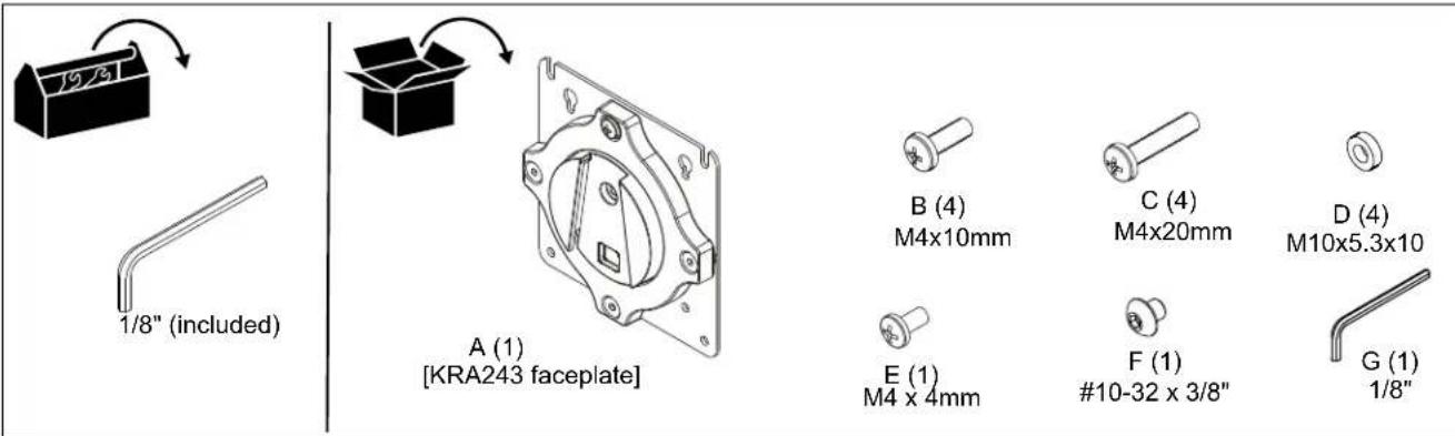
ASSEMBLY AND INSTALLATION
Mounting to K1 Mounts
- Refer to K1 Series Installation Instructions to use hardware B-D to mount display(s) to faceplate(s) (A).
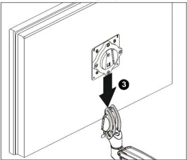
- Position display with faceplate (A) attached above mount. (See Figure 1)
- Slide faceplate (A) onto mounting head until quick release tab clicks into place. (See Figure 1)
text_image
Technical diagram showing a robotic arm holding a mechanical component with labeled parts and a numbered arrow indicating assembly step.Figure 1
Rotational Adjustment
NOTE: (Optional) Rotational adjustment may be locked by installing rotational locking screw (F) into back of faceplate. (See Figure 2)

text_image
5 OPT (F)Figure 2
- The monitor may be adjusted 90 degrees in either direction in order to provide a portrait view of the monitor. (See Figure 2)
- Use Phillips screwdriver to adjust rotational adjustment screw to adjust rotational tension. (See Figure 2)
Display Removal Security Screw
NOTE: In order to prevent display from being easily removed from mount using the quick release lever, install M4x4mm security screw (F) into lower hole on back of faceplate. (See Figure 3)

text_image
OPT (F)Figure 3

CHIEF®
Our Mounts. Your Vision.
Chief, a products division of Milestone AV Technologies
8800-003108 Rev00 ©2018 Milestone AV Technologies www.milestone.com
11/18
USA/International A 6436 City West Parkway, Eden Prairie, MN 55344
P 800.582.6480 / 952.225.6000
F 877.894.6918 / 952.894.6918
Europe A Franklinstraat 14, 6003 DK Weert, Netherlands
P +31 (0) 495 580 852
F +31 (0) 495 580 845
Asia Pacific A Office No. 918 on 9/F, Shatin Galleria
18-24 Shan Mei Street
Fotan, Shatin, Hong Kong
P 852 2145 4099
F 852 2145 4477
