AV116 - KVM Switch Avocent - Free user manual and instructions
Find the device manual for free AV116 Avocent in PDF.

User questions about AV116 Avocent
0 question about this device. Answer the ones you know or ask your own.
Ask a new question about this device
Download the instructions for your KVM Switch in PDF format for free! Find your manual AV116 - Avocent and take your electronic device back in hand. On this page are published all the documents necessary for the use of your device. AV116 by Avocent.
USER MANUAL AV116 Avocent
AV104/AV108/AV116 Switch
Installer/User Guide
EMI Statements
Products which are certified for EMC in the regions or countries indicated will have the require or statement on the product label. The applicable statement for that country is listed below.
Taiwan
警告使用者
Technical Support Site
If you encounter any installation or operational issues with your product, check the pertinent see this manual to see if the issue can be resolved by following outlined procedures. For additional visit https://www.VertivCo.com/en-us/support/.
TABLE OF CONTENTS
1 Product Overview 1
1.1 Features and Benefits..1....
2 Basic Operation 3
2.1 Using Keystroke Commands 4
2.1.1 Activation sequence commands 4
2.2 Using the On-Screen Display...5.....
2.3 Switching Between Targets 7
2.3.1 Local port commands 7
2.4 Enabling Port Binding 7
2.4.1 Pass-through USB port commands 8
2.5 Operating Scan Mode 8
2.5.1 Scan mode commands 8
2.6 Cascading Units 9
2.7 Upgrading Firmware.... 10
3 Appendix 11
Appendix A: Product Specification.... 11
1 PRODUCT OVERVIEW
The Vertiv™ AutoView™ AV104/AV108/AV116 is a single-user analog switch that supports up to four or 16 target devices and can be 0U or 1U rack-mounted or used as a desktop device. It supp keyboard, mouse and VGA video at the local user interface and USB and VGA or DisplayPort vic target devices. The switch does not have a web interface, therefore, all switching is done locally.
1.1 Features and Benefits
Depending on the model, the switch provides the following features and benefits:
- Buttons for switching among KVM target devices
• LED lights that indicate active and connected targets
• Hotkey switching functionality - On-screen display switching
- Three USB 2.0 Type-A ports for connecting a keyboard, mouse and flash drive for firmware upgrades
- Two USB 2.0 Type-A pass-through ports to allow you to use connected devices on a set target
• VGA video output to the local monitor of up to at least 2048 x 1536 pixels
NOTE: The 4-port model does not have on-screen display capability.
NOTE: The unit does not support an absolute mouse. Support is provided for a five-button, s relative mouse.
This page intentionally left blank.
2 BASIC OPERATION
The target devices connect to the product through a high density 26-pin connector and custom with USB and VGA connections to the target. A second custom cable has a built-in DisplayPort VGA adaptor that provides a DisplayPort connection to the target. The custom cables are available lengths of six or 12 feet. A third custom cable supports cascading between switches. It is identical VGA cables but is one foot in length. Contact your Vertiv™ representative to purchase the custom
Depending on the model, you can switch between target devices using the front panel buttons, the screen display or hotkeys. On-screen display switching is enabled on the AV108 and AV116 switch. a connected target device is powered, the corresponding LED on the bottom of the button illuminates orange. When the powered target device is selected, the corresponding LED on the top of the button illuminates green. The switch does not have a sleep or hibernation mode. It remains powered as power is provided.
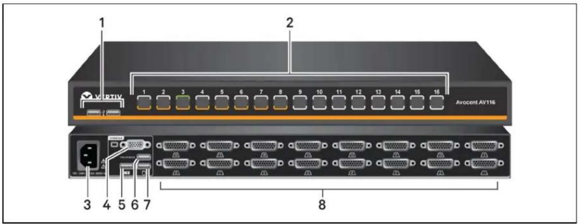
Figure 2.1 AV116 Front and Back Panel
text_image
1 2 3 4 5 6 7 8 Avocent AV116Table 2.1 Front and Back Panel Components
| ITEM DESCRIPTION | |
| 1 | USB 2.0 Type-A pass-through ports |
| 2 | Capacitive port selection touch buttons |
| 3 | AC C14 power input connector |
| 4 | HD15 VGA connector |
| 5 | USB 2.0 Type-A connector for a keyboard |
| 6 | USB 2.0 Type-A connector for a firmware upgrade peripheral |
| 7 | USB 2.0 Type-A connector for a mouse |
| 8 | HD26 target port connectors |
Figure 2.2 Front Panel Capacitative Buttons and LEDs

1

2

3
Table 2.2 Switch Buttons and LED Indicators
ITEM DESCRIPTION
1 Indicates target is not powered or not connected
2 Indicates target is connected and powered
3 Indicates target is connected, powered and selected
2.1 Using Keystroke Commands
The AV104/AV108/AV116 switch supports hotkey functionality. You can use hotkey functionality to dc the following:
- Switch KVM between ports
- Switch USB pass-through between ports
- Start and stop scan mode
The default command mode is Ctrl+Ctrl+ [COMMAND]. When activating command mode, Ctrl + Ctrl be pressed sequentially within one second of each other. You can change the default command r using activation sequence commands. The commands are not case sensitive.
When in command (hotkey) mode, only keystrokes are passed to the target computer. Mouse activ disabled.
To exit command mode:
Press Enter to accept the action.
NOTE: You must press Enter to complete the command mode action. There is no way to ab sequence unless you enter an incorrect key sequence.
2.1.1 Activation sequence commands
The activation sequence commands allow you to activate default command mode or change the activation sequence.
Table 2.3 Activation Sequence Commands
| KEY SEQUENCE | ACTION |
| Ctrl+Ctrl+H+1+Enter | Activates the default command mode (Ctrl+Ctrl). |
| Ctrl+Ctrl+H+2+Enter | Changes the activation sequence to Alt + Alt. |
| Ctrl+Ctrl+H+3+Enter | Changes the activation sequence to Shift + Shift. |
2.2 Using the On-Screen Display
In addition to using the front panel buttons and keystroke commands, you can use the on-screen to control port selection and to rename target devices, enable or disable port binding, display the version and adjust the scan time interval.
You can also rename supported targets from the on-screen display. Target names are limited to 2 English characters.
Since the on-screen display does not support mouse functionality, the arrow keys can be used to among the target devices.
To initiate the on-screen display with a list of targets:
Press Print Screen or press Ctrl+Ctrl+O+Enter.
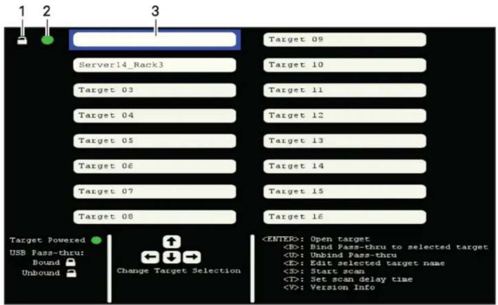
Figure 2.3 On-Screen Display Initial Window
text_image
1 2 3 Server14_Rack3 Target 03 Target 04 Target 05 Target 06 Target 07 Target 08 Target 09 Target 10 Target 11 Target 12 Target 13 Target 14 Target 15 Target 16 Target Powered USB Pass-thru: Bound Unbound Change Target SelectionTable 2.4 On-Screen Display Initial Window
ITEM DESCRIPTION
1 USB pass-through icon (unbound shown)
2 Target powered icon (powered shown)
3 Target field (selected target field shown)
A green circle appears next to powered targets, a locked icon appears next to a target bound USB pass-through and an unlocked icon appears next to an unbound target.
To bind or unbind a target:
-
Use the arrow keys to navigate to the target and press Enter.
-
Press B to bind the target.
-or-
Press U to unbind the target.
To assign or edit a target name:
- Use the arrow keys to navigate to the target field and press E.
- Type the name in the target field.
- Press Enter to save.
-or-
Press Esc to exit without saving.
To set a scan time and run a scan:
Figure 2.4 Enter Scan Time Dialog Box with Default Time

text_image
New Name Target 09 Target 02 Target 10 Target 03 Target 11 Target 04 Enter scan time (2 - 60 seconds) 30 Target 05 Target 06 Enter - Accept Target 07 Escape - Cancel Target 08 Target Powered USB Pass-thru: Bound Unbound Change Target Selection- Press T and press Backspace to clear the existing scan time value.
NOTE: The scan time value indicates seconds. The default scan time is 30 seconds.
- Enter a value between 02 and 60.
- Press Enter to save the scan time.
- Press S to start the scan.
To view the firmware version:
Press V.
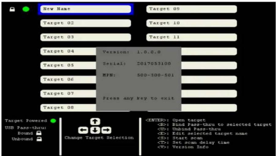
Figure 2.5 Firmware Version Window
text_image
New Name Target 09 Target 02 Target 10 Target 03 Target 11 Target 04 Version: 1.0.0.0 Serial: 2017053100 MPN: 500-300-501 Target 05 Target 06 Target 07 Press any key to exit Target 08 Target Powered USB Pass-thru: Bound Unbound Change Target Selection2.3 Switching Between Targets
You can switch between connected target devices using the unit's front panel buttons, keystroke commands or through the on-screen display. The target device does not have to be powered on selected. The switch automatically selects port 1 by default.
2.3.1 Local port commands
The local port commands allow you to select a KVM target and toggle between current and previ active ports.
If you are using the on-screen display to toggle between and select ports, your selection is actively immediately. If you are in command mode and selecting ports by keystroke, you must exit command to enable mouse movement and keystrokes on the target device. Pressing Enter or ESC at the end of a keystroke sequence exits command mode.
Table 2.5 Local Port Commands
| KEYSTROKE VALUE ACTION | ||
| Ctrl+Ctrl+[nn]+Enter | Depending on the switch model, enter a value between 01 and 16 where nn is the value for example, 01 selects port 1. Select formative KVM target. | |
| Ctrl+Ctrl+L+[Backspace]+ [Enter or ESC] | N/A | Toggles between the current and previous active ports. Press and release Backspace until you reach the desired port. |
| Ctrl+Ctrl+L+[X ARROW]+ [Enter or ESC] | Press the up, down, right or left arrow variable X ARROW. | Selects the next higher numbered port (up and right arrows) or selects the next lower numbered port (down and left arrows). Press and release the arrow key until you reach the desired port. |
2.4 Enabling Port Binding
By default, port binding is enabled for the two front panel USB pass-through ports. Port binding two ports to be connected to the same target as the selected KVM session regardless of the t select through the front panel buttons, keystroke commands or the on-screen display. When binding
enabled, the internal USB hub and any devices that are connected to the front USB ports are automatically mapped to the target that is connected to the user through the local port connection. When you switch the KVM connection to a different port, the USB pass-through also switches to
The pass-through ports are connected to a target by an on-board hub and a second USB connection. Each target port on the unit's back panel has two USB cables with connectors. The cable with connector is for the KVM connection and the cable with the yellow connector is for the USB pass connection. The two front panel pass-through ports are mapped to an internal USB hub and push the yellow USB cable. When you switch to a port, the keyboard and mouse traffic from the local through the black connector to the target.
You can enable and disable binding using keystroke commands or the on-screen display. When po binding is disabled, pass-through port selection is independent of the KVM session selection and y switch a USB hub and its connected devices to a port different from what you are connected t only use keystroke commands to select a target for the pass-through ports. If the target selected through is different from the target selected for the KVM session, the green LED on the selecte through port flashes slowly and the green LED for the selected KVM session illuminates.
2.4.1 Pass-through USB port commands
The pass-through USB port commands allow you to select a target PC to control the USB hub port or disable the ports and enable or disable port binding. When you initiate keystroke port selection pass-through port binding is automatically disabled.
Table 2.6 Pass-through USB Port Commands
| KEY SEQUENCE VALUE ACTION | ||
| Ctrl+Ctrl+U+[nn]+Enter | Enter a value between 01 and 16 value format. | When Selects is the PC target that controls the USB hub ports. |
| Ctrl+Ctrl+U+C+Enter | N/A | Moves USB hub ports to currently selected KVM session channel. |
| Ctrl+Ctrl+U+D+Enter | N/A | Disables USB hub ports. No target connected to hub. |
| Ctrl+Ctrl+B++Enter | N/A | Enables port binding. |
| Ctrl+Ctrl+B-+Enter | N/A | Disables port binding. |
2.5 Operating Scan Mode
The switch supports Scan mode which allows you to scan for newly connected target devices. Yc control Scan mode with keystroke commands or from the on-screen display. You can set a scan intervals between 2 and 60 seconds. The default scan interval is 30 seconds. The target device connected to a target port and powered on to be detected during Scan mode.
2.5.1 Scan mode commands
The Scan mode commands allow you to determine scan intervals, start or stop a scan and enable disable mouse movement. When you initiate interval scanning, USB pass-through port binding is automatically disabled.
When interval scanning is stopped, USB pass-through port binding is automatically enabled unless y disable it by keystroke command (Ctrl+Ctrl+B-]+Enter) or through the on-screen display.
Table 2.7 Scan Mode Commands
| KEY SEQUENCE VALUE ACTION | ||
| Ctrl+Ctrl+S+[nn]+Enter | Enter a value between 02 and 60 where Set on the interval scan time; the default setting is value format. | 30 seconds. |
| Ctrl+Ctrl+S+G+Enter | N/A | Starts the interval scan function. |
| Ctrl+Ctrl+S+H+Enter | N/A | Stops the interval scan function. |
| Ctrl+Ctrl+SM++Enter | N/A | Enables mouse movement to stop scanning. |
| Ctrl+Ctrl+SM-+Enter | N/A | Disables mouse movement to stop scanning. |
2.6 Cascading Units
The switches support one level of switch-to-switch cascading. You can connect a secondary switch to each port of a primary switch. You can connect targets to each port on a secondary switch, but you cannot connect additional switches to a secondary switch.
A cascading cable can be used to connect from a target port on the top-tier unit into a console port of the second-tier unit. You can use a cascading cable or the standard VGA cable for the connection.
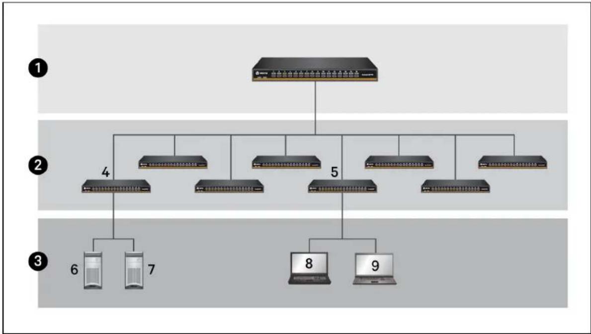
Figure 2.6 Cascading Units Example Configuration
flowchart
graph TD
    A["Central Server"] --> B["Server 1"]
    A --> C["Server 2"]
    A --> D["Server 3"]
    A --> E["Server 4"]
    A --> F["Server 5"]
    A --> G["Server 6"]
    A --> H["Server 7"]
    A --> I["Server 8"]
    A --> J["Server 9"]
Table 2.8 Cascading Units Example Configuration Components
| ITEM | DESCRIPTION |
| 1 | Primary switch - You can connect one secondary switch to each port on the primary switch. |
| 2 | Secondary switches - You can connect one target to each port on each of the secondary switches. |
| 3 | Secondary switch targets - You can only connect target devices to secondary switches. Secondary switches do not support third-tier switch connections. |
| 4 | Secondary switch connected to port 1 on the 16-port primary switch |
ITEM DESCRIPTION
5 Secondary switch connected to port 5 on the 16-port primary switch
6 Target device connected to port 1 on a 16-port secondary switch
7 Target device connected to port 2 on a 16-port secondary switch
8 Target Linux® device connected to port 8 on a 16-port secondary switch
9 Target Mac® device connected to port 12 on a 16-port secondary switch
To access the secondary unit's target devices using a hotkey sequence:
- On the primary switch, select the port that is connected to the secondary switch.
- Press Ctrl+Ctrl+T+[nn]+Enter where the variable nn signifies the two-digit port number connected to the cascaded unit.
NOTE: The primary and secondary hotkeys in an activation sequence must match (for example, Ctrl+Ctrl, Alt+Alt or Shift+Shift) to use the on-screen display hotkey combination.
2.7 Upgrading Firmware
You can upgrade the switch's firmware by connecting a USB Flash drive loaded with the latest first file to the back panel USB 2.0 Type-A connector port. The Flash drive must be FAT32 formatted loaded with the following upgrade files:
- cricket.bin - upgrade file for the main processor
- tpu.bin - upgrade files for target processors
- fpga.bin - upgrade for field-programmable gate array (FPGA)
NOTE: The fpga.bin file is only applicable for units with on-screen display capability.
During the process, the switch determines if the upgrade files' versions detected on the USB Flash are different from the versions on the switch. If new versions are detected, the unit automatically upgrades and reboots. When the switch is updating, both LEDs for each port illuminate sequentially scrolling pattern until the update is complete. When the update is complete, the LEDs flash on a indicating the switch rebooted and is ready for use.
NOTE: You can also use this process to downgrade firmware.
To upgrade the firmware:
- Download and copy the upgrade files to the top level of the Flash drive.
- Insert the Flash drive into the firmware upgrade USB 2.0 Type-A port on the back panel
To confirm the firmware version:
- Before removing the Flash drive from the switch, press Ctrl+Ctrl+V+Enter to write the version.txt file to the drive.
- Remove the Flash drive from the switch and insert it into a computer.
- Navigate to and open the version.txt file on the Flash drive to view the unit's firmware
3 APPENDIX
This section contains the Product Specifications.
Appendix A: Product Specification
The following table lists the product specifications for the Vertiv™ AutoView™ AV104/AV108/AV116 switches.
Table 3.1 Product Specification
| SPECIFICATION DESCRIPTION | |
| Enclosure Metal | |
| Power input connector 100-240 V, 50-60 Hz AC, single IEC 60320 C14 connector | |
| AV104: 4 | |
| Number of support target devices | AV108: 8AV116: 16 |
| Dimensions WxHxD: 17.1 x 1.70 x 4.75 inches (434.35 x 43.18 x 120.65 mm) | |
| Operating temperature 32° to 122° F (0° to 50° C) | |
| Storage temperature | -22° to 158° F (-30° to 70° C) |
| Operating humidity | 20-85% relative humidity, non-condensing |
| Storage humidity | 5-95% relative humidity at a maximum wet bulb temperature of 38.7°C |
This page intentionally left blank.

VERTIV™
VertivCo.com | Vertiv Headquarters, 1050 Dearborn Drive, Columbus, OH, 43085, USA
© 2017 Vertiv Co. All rights reserved. Vertiv and the Vertiv logo are trademarks or registered trademarks of Vertiv Co. All other names and logos referred to are trade names, trademarks or registered trademarks of their respective owners. While every precaution has been taken to ensure accuracy and completeness herein, Vertiv Co. assumes no responsibility, and disclaims all liability, for damages resulting from use of this information or for any errors or omissions. Specifications are subject to change without notice.