CHGCT36I-1N - Chargeur pour appareil mobile V7 - Free user manual and instructions
Find the device manual for free CHGCT36I-1N V7 in PDF.

User questions about CHGCT36I-1N V7
0 question about this device. Answer the ones you know or ask your own.
Ask a new question about this device
Download the instructions for your Chargeur pour appareil mobile in PDF format for free! Find your manual CHGCT36I-1N - V7 and take your electronic device back in hand. On this page are published all the documents necessary for the use of your device. CHGCT36I-1N by V7.
USER MANUAL CHGCT36I-1N V7
natural_image
Line drawing of a simple electrical cabinet with wheels and handle (no text or symbols)TABLE OF CONTENTS
SAFETY AND WARNINGS
Safety and warnings 2
GETTING STARTED
Unboxing 3
Cart Diagram 6
Locking the cart 10
SETUP AND USAGE
Guidelines 11
Charging System 16
Plug cart into outlet 17
Customize Charging 18
Intelligent charging 21
TECHNICAL SPECIFICATIONS
Technical specifications 22
WARRANTY
Warranty 24
SAFETY AND WARNINGS
CAUTION

This symbol on the product indicates important literature concerning operation and maintenance. Do not remove or alter labels.
To reduce risk of electric shock only use this product indoors.
- This product is heavy. Use caution handling and keep upright. Do not attempt to unpack or move it unassisted.
- Use caution when unpacking and save the packing material for later use. Scratches and other damage caused by mishandling is not covered by the warranty.
- Do not allow anyone to sit, stand, or climb on this product.
- Do not block the ventilation holes used for air circulation.
- Do not overload heavy objects on or inside this product.
- Before moving this product, disconnect the power from the wall outlet.
- While moving this product, make sure the power cord is secured.
• This product should always be used by adults or with adult supervision. - Never unplug this product from the outlet when hands are wet or by pulling the power cord.
- Do not use an extension cord in conjunction with this product.
- Connection to any other type of receptacle other than a two-pole, three-wire grounded / receptacle may result in shock hazard as well as violate local electrical codes.
- In the event of an emergency, disconnect the power cord from the AC power outlet.
Do not plug the input of this product into its own output.
Do not attach an additional extension cord, power strip, or surge protector to this product.
- Do not attach non-computer-related items, such as medical equipment, life-support equipment, microwave ovens, or vacuum cleaners to this product.
- Place cables in such a way that they won't be pulled or snagged, and no one can step on or trip over them.
- Do not attempt to disassemble this product. This product contains no user replaceable parts. Only factory service personnel may perform repairs.
If this product is misused, incorrectly operated or repaired, the warranty will be void.
Remove objects from top while moving.
10 kg max load on top.
Do not open more than one shelf at a time.
Place items in the bottom shelf first.
Always spread items as much as possible on the shelves.
Only place items in slots.
GETTING STARTED
Unboxing:
CAUTION

Two person handling required
1 | Remove all parts of the packaging. Use caution when unpacking and save the packing material for later use. |
2 | Ensure that brakes are locked. Remove screws (using a screwdriver) Remove wooden blocks |
3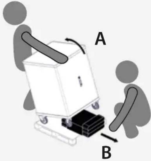 | At the cart with caution by rotating it on the wheels equipped with brakes.While one person is titling the cart, the other person should:Remove the cardboard insertThen gently lower the cart back down to the pallet. |
4 | Unlock the brakes and gently push the cart down the pallet starting with the wheels that have brakesBck the brakes againIt the cart on the wheels that have brakesRemove the palletThen gently lower the cart down to the ground. |
Package includes:

natural_image
Line drawing of a two-door industrial machine with wheels and a handle (no text or symbols)CHGCT36I-1N

natural_image
Line drawings of two key illustrations: one with a key and one with a key (no text or symbols)Keys

natural_image
Line drawing of two types of electrical plug connectors (no text or symbols)Power cord

natural_image
Blank rounded rectangle shape with no text or symbolsLaser engraving plate
Cart Diagram

text_image
Front Door handle and locks Rear Rubber bumpers Caster Power strip Power Adapter slots
text_image
Rear Power Switch
text_image
Front Device slots Locking caster
text_image
Front Charging LED indicators 1-12 13-24 25-36 Power 10 11 12Locking the cart
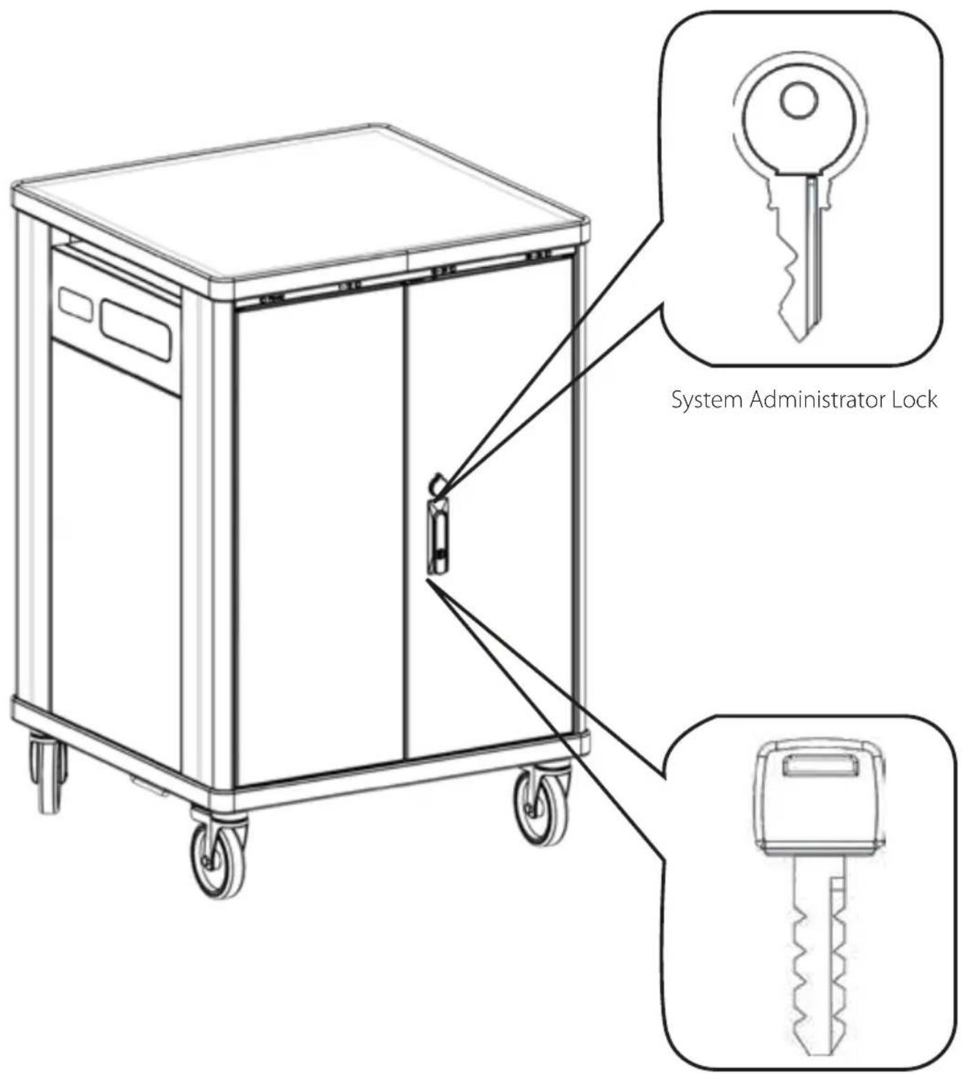
text_image
System Administrator LockUser Lock
SETUP AND USAGE
For best performance follow these guidelines:
- Spread the devices as much as possible on the three shelves. For example, if you have 21 devices, load 7 on each shelf.
Load the devices starting from the lowest shelf.
Avoid using defective/broken/ repaired power supply units.
Avoid using cables with exposed wires or with home-made repairs with tape.
• Always use the original power supply units for your devices, avoid using power supply units that requires adapters on the connector
Always use power supply units with US plug. Avoid using global power adapters.

natural_image
Line drawing of a rectangular industrial machine with wheels and a lid (no text or symbols)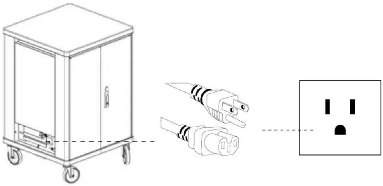
natural_image
Technical line drawing of a portable electrical cabinet with two connected plug plugs and a separate socket (no text or symbols)Plug in AC adapters into power strips

natural_image
Technical line drawing of an electrical enclosure with a close-up view showing internal components and a separate schematic symbol (no text or labels)Place power adapters into slots

natural_image
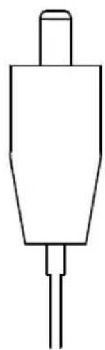
Simple line drawing of a rectangular object with a protruding rod (no text or symbols)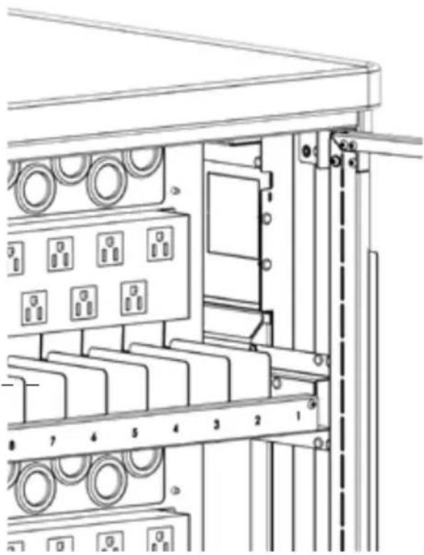
natural_image
Technical line drawing of an electrical cabinet with multiple panel switches and wiring (no text or labels)Insert the cable through the pass-trough holes
natural_image
Simple line drawing of a three-pin electronic component (no text or symbols)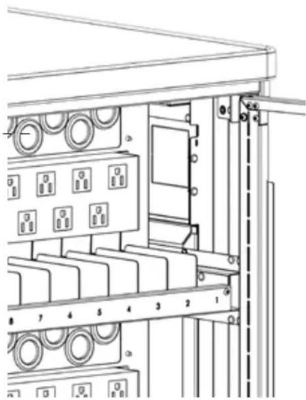
natural_image
Technical line drawing of an electrical cabinet with multiple panel switches and wiring (no text or symbols)Place the cable on the cable holder dividers

natural_image
Technical line drawing of a mechanical device with no visible text or symbolsBefore running the cable, unlock the mechanism shown in the image below

text_image
Open
text_image
ClosedPut devices inside the slots
text_image
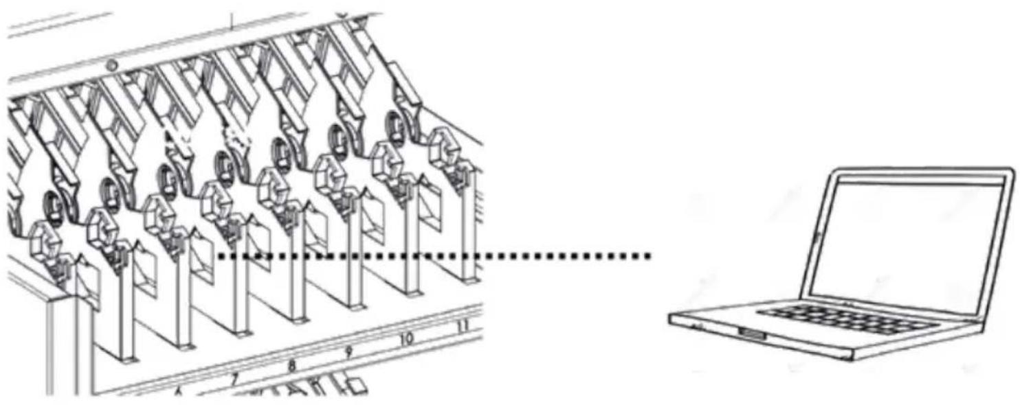
Technical diagram showing a mechanical assembly with numbered components and a laptop displaying a blank screen.Plug the power adapters in to your devices so they can charge
Charging system
Charging all of your devices at one time can overload a typical circuit. V7 Charge Carts are equipped with intelligent charging that automatically switches the power to the devices that need it first. It has sensors for each power strip in the charge cart, and constantly monitors the incoming current from the wall outlet. It limits the initial inrush current to protect the devices when first powered on. As devices charge it, continuously monitors the amount of current to keep the maximum number of devices charging while protecting the devices and the building's electrical system.
The LED indicators will show you which power strips are currently charging.

text_image
Power 1-12 13-24 25-36 17Plug cart into outlet
CAUTION

Lock the front wheels first
Turn off the main power switch, make all the indicated connections and turn on the power switch again.
natural_image
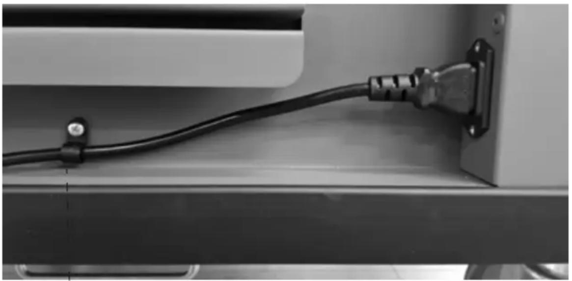
Close-up of a black cable with a plug inserted into a device panel (no visible text or symbols)The power cable strain relief mechanism ensures that the cable is not stressed incorrectly. If the cable needs replacing, simply remove the screw.
Customize charging
CAUTION

Only an instructed person should change these settings.
CAUTION

Lock the front wheels. Disconnect the main power cable and make sure that the main switch is turned off.

text_image
Remove screws to access the boardSW1 - Mains Voltage
CAUTION

Do not change these settings.

110V
SW2 - Time charge
This rotary switch allows you to select the duration of the power cycle when cycle mode is used.
| Position Duration/Note | |
| 0 RESERVED - FACTORY TESTING ONLY | |
| 1 | RESERVED for SLCTHG36-1N accessory (optional) |
| 2 | 15 minutes |
| 3 | 20 minutes - DEFAULT |
| 4 | 25 minutes |
| 5 | 30 minutes |
| 6 | 35 minutes |
| 7 | 40 minutes |
| 8 | 50 minutes |
| 9 | 60 minutes |
Board for charge customization

text_image
SW1 SW2 SW3SW3 - Maximum current settings
This rotary switch allows you to select the maximum allowed current for the entire cart.
| Position Duration/Note | |
| 0 RESERVED | |
| 1 | 11.0 A |
| 2 | 11.5 A |
| 3 | 12.0 A |
| 4 | 12.5 A |
| 5 | 13.0 A |
| 6 | 13.5 A |
| 7 | 14.0 A - DEFAULT |
| 8 | 14.5 A |
| 9 | 15.0 A |
Led Settings
Change brightness of the LEDs as follows:
- Open doors on the back of the cart
- Locate the push button on the maintenance box (left-center)
- Push the button repeatedly to cycle through the available settings

text_image
Buttonof to
| # of touches Brightness settings | |
| 1 | 10% |
| 2 | 20% |
| 3 | 40% |
| 4 | 60% |
| 5 | 80% |
| 6 | 100% |
| 7 | Return to 1 |
Intelligent Charging
This cart is equipped with an intelligent charging system that manages the power and is customizable:
- At power-up
- One power strip will be charged at a time for a short period in order to check current need. Power LED indicator is ON and the LED indicators blink fast.
- If total current need on the cart is less than 15A (1650W at 110V) and single current need for each power strip is less than 8.5A (935W at 110V), all power strips will be active. Power LED indicator is ON and LEDs will fade on/off slowly.
- If total current need of the cart is more than 15A (1650W at 110V) but the single current need for each power strip is less than 8.5A (935W at 110V), then one power strip will be charged at a time for 20 minutes each (this duration is customizable – see "Custom settings" below). Corresponding LED indicator will fade on/off slowly.
- During Charging
- If the power demand of a single shelf exceeds the maximum allowed power (935W - 8.5A at 110V) then the cycle mode is started with 20 minute cycle for each drawer.
- Once all devices in a shelf complete their charge, the corresponding LED indicator remains ON.
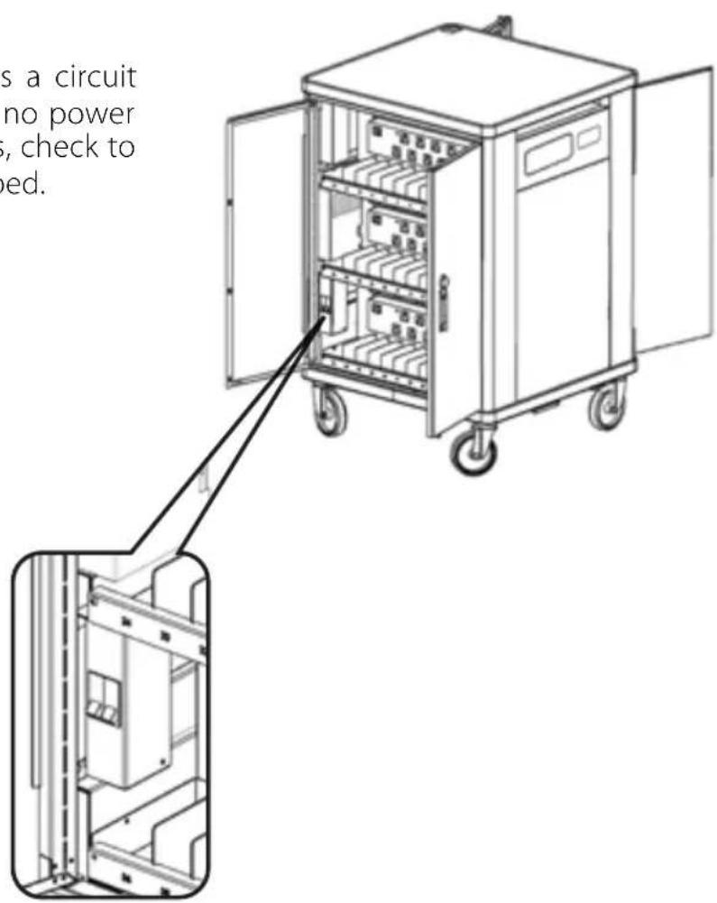
Circuit Breaker
The Power Switch also acts as a circuit breaker on the cart. If there is no power to internal and external outlets, check to see if the circuit breaker is tripped.
text_image
s a circuit no power , check to ed.TECHNICAL SPECIFICATIONS

| NUMBER DEVICE SPACES | 36 |
| ORGANIZATION AND CONVENIENCE | Flexible device dividers with cable channels and numbered device slots, numbered individual power adapter slots, robust cable amanagement throughout the cart, soft close sliding shelves, recessed handles |
| WARRANTY | 10 year mechanical / 5 year electrical |
| PACKAGE CONTENTS | Charging Cart, Power Cord 6 ft (1.83 m), Manual, Laser engraving plate |
| INPUT VOLTAGE (MAX) | 110VAC/120VAC, 15A, 60HZ |
| OUTPUT VOLTAGE (MAX) | 110VAC/120VAC, 15A, 60HZ |
| ROLLING CASTER SIZE | 5 in (125 mm) |
| PRODUCT DIMENSIONS | 27.17 x 25.98 x 41.06 in (690 x 660 x 1043 mm) |
| PRODUCT WEIGHT | 231.49 lbs (105 kg) |
| PACKAGE SIZE | 28.74 x 27.56 x 47.24 in (730 x 700 x 1200 mm) |
| PACKAGE WEIGHT | 264.56 lbs (120 kg) |
| DEVICE SLOT DIMENSIONS | 15.23 x 1.38 x 10.35 in (387 x 35 x 263 mm) |
| POWER ADAPTER SLOT DIMENSIONS | 3.66 x 1.65 x 4.25 in (93 x 42 x 108 mm) |
| CERTIFICATIONS | IEC 62368-1 (UL 62368-1 and CSA 62368-1) |
Ten Year Limited Warranty
V7 Limited Manufacturer's Warranty covers this Product against defects in materials or workmanship from the date of purchase for a period of ten (10) years for mechanical parts and five (5) years for electrical parts. Liability under this limited warranty shall in no event exceed the cost of replacement or the original cost of the product at the time of purchase. In the event of product discontinuance or unavailability wherein failure has occurred the product shall, at the sole discretion of Manufacturer, be replaced to the first purchaser with a substantially similar product of equal or lesser value or the first purchaser shall be provided with a refund equal to the original i.e. first purchaser purchase price. This limited warranty does not cover the repair of cracked, scratched, broken or modified plastic or other cosmetic damage; or parts that have been altered, defaced or removed. Also, it does not apply to repairs or replacement necessitated by any cause beyond the control of the Manufacturer or a servant or agent of the Manufacturer including, but not limited to, any malfunction, defects or failures which in the opinion of Manufacturer were caused by or resulting from unauthorized service or parts, improper maintenance, operation contrary to furnished instructions, shipping or transit accidents, modification or repair by the user, abuse, misuse, neglect, accident, fire, flood, or other acts of God, incorrect line voltage or normal wear and tear, or which did not exist at the time when the Product was purchased. This limited warranty does not apply to damage that occurs during unpacking, setup, or installation; removal of the product for repair; reinstallation of the product after repair, or shipping cost of the product for any purpose. There are no other expressed warranties, whether written or oral, other than this printed limited warranty.
All implied warranties, including without limitation the implied warranties or merchantability or fitness for a particular purpose, are limited to the durations of this limited warranty. In no event shall V7 be liable for incidental or consequential damages of any nature whatsoever, including but not limited to lost profit or commercial loss, to the full extent those damages can be disclaimed by law. Some countries do not allow the exclusion or limitation of liability arising from implied warranties, or limitation of the duration of implied warranties, so the preceding limitations or exclusions may not apply to all purchasers. This limited warranty is subject to the laws of the relevant jurisdiction, being the country where the product is originally purchased. This limited warranty shall only apply to the extent permitted by applicable national legislation governing the sale of consumer goods. The rights and remedies that consumers enjoy under such consumer protection laws shall not be limited. This warranty is valid only in the country where the product is originally purchased. Additional information can be found at www.V7world.com.
You may execute this warranty where you purchased in accordance with the exchange policy of the establishment. At any time thereafter during the term of this warranty, please refer to the authorized distributor of your jurisdiction.
Ingram Micro, LP Canada
55 Standish Court
Mississauga, ON, L5R 4A1, Canada
Mexico
Ingram Micro Mexico, S.A. de C.V.
D-85609 Dornach / Munich, Germany
New Zealand
Ingram Micro NZ Ltd
78 Apollo Drive, Albany
Auckland 0642, New Zealand
India
Ingram Micro India Limited
Godrej IT Park, B-Block, 5th Floor
Pirojsahanagar, L.B.S. Road,
Vikhroli (West), Mumbai-400 079, India
Australia
Ingram Micro Pty Ltd
61 Dunning Ave, Rosebery
NSW 2018, Australia
Brazil
Ingram Micro Brasil Ltda
Av. Francisco Matarazzo, 1500 – Torre NY
Sao Paulo, SP 05001-100, Brazil
Hong Kong
Ingram Micro (China) Limited
Room 1205-18, 12/F, Tower 1,
Millennium City,
388 Kwun Tong Road, Kowloon, Hong Kong
RECOMMENDATIONS FOR DISPOSAL
Correct disposal of the WEEE product (waste from electrical and electronic equipment)

The symbol shown on the product, on the accessories and on the documentation (Fig.1) indicates that the product and its electronic accessories (such as cables, adapters, electrical parts in general) must not be disposed of with other unsorted waste at the end of their life cycle.
To avoid any damage to the environment, the user is invited to separate the product and the aforementioned accessories from other types of waste. The user company will be responsible for arranging the collection of waste and managing the steps necessary for proper disposal.
IMECON S.r.l. as a manufacturer it is duly registered in the Register of Manufacturers of Electrical and Electronic Equipment with registration IT20110000012577.
Fig. 1