
SCP-2370RH - Security Camera Hanwha - Free user manual and instructions
Find the device manual for free SCP-2370RH Hanwha in PDF.

| Product Type | PTZ Security Camera with IR Illuminator |
| Dimensions (Φ×H) | 248 x 399.5 mm |
| Weight | 6 kg |
| Power Supply | 24V AC ±10%, 50/60Hz; 15W (max 90W with fan & heater) |
| Image Sensor | 1/4" Super HAD CCD |
| Horizontal Resolution | Color: 600 TV lines, B/W: 700 TV lines |
| Min. Illumination | 0 Lux (IR on); Color: 0.2 Lux, B/W: 0.02 Lux (50 IRE @ F1.6) |
| Lens | 37x optical zoom (3.5~129.5mm), 16x digital zoom (total 592x) |
| Pan/Tilt Range | Pan: 360° endless; Tilt: -5° ~ 185° |
| Pan/Tilt Speed | Preset: 250°/sec; Manual: 0.024°/sec ~ 120°/sec |
| Preset Positions | Up to 255 |
| Day/Night Mode | Auto (ICR), Color, B/W |
| IR Illuminator Range | Up to 100 meters |
| Ingress Protection | IP66 |
| Operating Temperature | -50°C ~ +55°C |
| Communication | RS-485/422, Coaxial (Pelco Coaxitron); multiple protocols (Samsung, Pelco, Panasonic, etc.) |
| Alarm I/O | 8 inputs, 3 outputs (relay: 30VDC/2A, 125VAC/0.5A, 250VAC/0.25A) |
| Warranty | 3 years |
Frequently Asked Questions - SCP-2370RH Hanwha
User questions about SCP-2370RH Hanwha
0 question about this device. Answer the ones you know or ask your own.
Ask a new question about this device
Download the instructions for your Security Camera in PDF format for free! Find your manual SCP-2370RH - Hanwha and take your electronic device back in hand. On this page are published all the documents necessary for the use of your device. SCP-2370RH by Hanwha.
USER MANUAL SCP-2370RH Hanwha
©2012 Samsung Techwin Co., Ltd. All rights reserved.
Trademark
SAMSUNG TECHWIN

is the registered logo of Samsung Techwin Co., Ltd.
The name of this product is the registered trademark of Samsung Techwin Co., Ltd.
Other trademarks mentioned in this manual are the registered trademark of their respective company.
Restriction
Samsung Techwin Co., Ltd shall reserve the copyright of this document. Under no circumstances, this document shall be reproduced, distributed or changed, partially or wholly, without formal authorization of Samsung Techwin.
Disclaimer
Samsung Techwin makes the best to verify the integrity and correctness of the contents in this document, but no formal guarantee shall be provided. Use of this document and the subsequent results shall be entirely on the user's own responsibility. Samsung Techwin shall have the right to change the contents of this manual without prior notice for the purpose of enhanced performance.
Warranty
If the product does not operate properly in normal conditions, please let us know. Samsung Techwin will resolve the problem for free of charge. The warranty period is 3 years. However, the followings are excluded:
- If the system behaves abnormally because you run a program irrelevant to the system operation.
- Deteriorated performance or natural worn-out in process of time
◆ Design and specifications are subject to change without prior notice.
CAUTION
RISK OF ELECTRIC SHOCK. DO NOT OPEN

CAUTION: TO REDUCE THE RISK OF ELECTRIC SHOCK, DO NOT REMOVE COVER (OR BACK) NO USER SERVICEABLE PARTS INSIDE. REFER SERVICING TO QUALIFIED SERVICE PERSONNEL.
This symbol indicates that dangerous voltage consisting a risk of electric shock is present within this unit.
This symbol indicates that there are important operating and maintenance instructions in the literature accompanying this unit.
WARNING
- To reduce the risk of fire or electric shock, do not expose this appliance to rain or moisture.
- To prevent injury, this apparatus must be securely attached to the floor/wall in accordance with the installation instructions.
- REPLACE WITH SAME TYPE 250V T4AL FUSE (F101, F201, F1)
WARNING
- Be sure to use only the standard adapter that is specified in the specification sheet. Using any other adapter could cause fire, electrical shock, or damage to the product.
- Incorrectly connecting the power supply or replacing battery may cause explosion, fire, electric shock, or damage to the product.
- Do not connect multiple cameras to a single adapter. Exceeding the capacity may cause abnormal heat generation or fire.
- Securely plug the power cord into the power receptacle. Insecure connection may cause fire.
- When installing the camera, fasten it securely and firmly. The fall of camera may cause personal injury.
- Do not place conductive objects (e.g. screwdrivers, coins, metal parts, etc.) or containers filled with water on top of the camera. Doing so may cause personal injury due to fire, electric shock, or falling objects.
- Do not install the unit in humid, dusty, or sooty locations. Doing so may cause fire or electric shock.
- If any unusual smells or smoke come from the unit, stop using the product. In such case, immediately disconnect the power source and contact the service center. Continued use in such a condition may cause fire or electric shock.
- If this product fails to operate normally, contact the nearest service center. Never disassemble or modify this product in any way. (SAMSUNG is not liable for problems caused by unauthorized modifications or attempted repair.)
- When cleaning, do not spray water directly onto parts of the product. Doing so may cause fire or electric shock.
CAUTION - Danger of explosion if battery is incorrectly replaced. Replace only with the same or equivalent type.
CAUTION
- Do not drop objects on the product or apply strong blows to it. Keep away from a location subject to excessive vibration or magnetic interference.
- Do not install in a location subject to high temperature (over 55^ C), low temperature (below -50^ C), or high humidity. Doing so may cause fire or electric shock.
- If you want to relocate the already installed product, be sure to turn off the power and then move or reinstall it.
-
Remove the power plug from the outlet when there is a lighting storm. Neglecting to do so may cause fire or damage to the product.
-
Keep out of direct sunlight and heat radiation sources. It may cause fire.
- Install it in a place with good ventilation.
- Avoid aiming the camera directly towards extremely bright objects such as sun, as this may damage the CCD image sensor.
- Apparatus shall not be exposed to dripping or splashing and no objects filled with liquids, such as vases, shall be placed on the apparatus.
- Do not expose the camera to radioactivity. Radioactivity exposure may damage the CCD.
FCC Statement
This device complies with part 15 of the FCC Rules. Operation is subject to the following two conditions :
1) This device may not cause harmful interference, and
2) This device must accept any interference received including interference that may cause undesired operation.
CAUTION
This equipment has been tested and found to comply with the limits for a Class A digital device, pursuant to part 15 of FCC Rules. These limits are designed to provide reasonable protection against harmful interference when the equipment is operated in a commercial environment.
This equipment generates, uses, and can radiate radio frequency energy and, if not installed and used in accordance with the instruction manual, may cause harmful interference to radio communications.
Operation of this equipment in a residential area is likely to cause harmful interference in which case the user will be required to correct the interference at his own expense.
IC Compliance Notice
This Class A digital apparatus meets all requirements of the Canadian Interference.-Causing Equipment Regulations of ICES-003.

Correct Disposal of This Product (Waste Electrical & Electronic Equipment)
(Applicable in the European Union and other European countries with separate collection systems) This marking on the product, accessories or literature indicates that the product and its electronic accessories (e.g. charger, headset, USB cable) should not be disposed of with other household waste at the end of their working life. To prevent possible harm to the environment or human health from uncontrolled waste disposal, please separate these items from other types of waste and recycle them responsibly to promote the sustainable reuse of material resources.
Household users should contact either the retailer where they purchased this product, or their local government office, for details of where and how they can take these items for environmentally safe recycling. Business users should contact their supplier and check the terms and conditions of the purchase contract. This product and its electronic accessories should not be mixed with other commercial wastes for disposal.

Correct disposal of batteries in this product
(Applicable in the European Union and other European countries with separate battery return systems.) This marking on the battery, manual or packaging indicates that the batteries in this product should not be disposed of with other household waste at the end of their working life. Where marked, the chemical symbols Hg, Cd or Pb indicate that the battery contains mercury, cadmium or lead above the reference levels in EC Directive 2006/66. If batteries are not properly disposed of, these substances can cause harm to human health or the environment.
To protect natural resources and to promote material reuse, please separate batteries from other types of waste and recycle them through your local, free battery return system.
4\_ safety information
important safety instructions
- Read these instructions.
- Keep these instructions.
- Heed all warnings.
- Follow all instructions.
- Clean only with dry cloth.
- Do not block any ventilation openings. Install in accordance with the manufacturer's instructions.
- Do not install near any heat sources such as radiators, heat registers, or other apparatus (including amplifiers) that produce heat.
- Do not defeat the safety purpose of the polarized or grounding-type plug. A polarized plug has two blades with one wider than the other. A grounding type plug has two blades and a third grounding prong. The wide blade or the third prong is provided for your safety. If the provided plug does not fit into your outlet, consult an electrician for replacement of the obsolete outlet.
-
Protect the power cord from being walked on or pinched particularly at plugs, convenience receptacles, and the point where they exit from the apparatus.
-
Only use attachments/accessories specified by the manufacturer.
-
Use only with the cart, stand, tripod, bracket, or table specified by the manufacturer, or sold with the apparatus. When a cart is used, use caution when moving the cart/ apparatus combination to avoid injury from tip-over.
-
Unplug this apparatus during lightning storms or when unused for long periods of time. When a cart is used, use caution when moving the cart/apparatus combination to avoid injury from tip-over.
-
Refer all servicing to qualified service personnel. Servicing is required when the apparatus has been damaged in any way, such as powersupply cord or plug is damaged, liquid has been spilled or objects have fallen into the apparatus, the apparatus has been exposed to rain or moisture, does not operate normally, or has been dropped.


Apparatus shall not be exposed to dripping or splashing and no objects filled with liquids, such as vases, shall be placed on the apparatus
WARNING
To prevent injury, this apparatus must be securely attached to the floor/wall in accordance with the installation instructions.
CAUTION
These servicing instructions are for use by qualified service personnel only. To reduce the risk of electric shock, do not perform any servicing other than that contained in the operating instructions unless you are qualified to do so.
DETAILED WARNINGS AND CAUTIONS
- Avoid operating the camera for long durations under high temperatures and in high humidity. Excessive heat can shorten the lifespan of the camera components.
- Do not install or place the camera near any heat sources.
- Do not expose the camera to a direct light. If a strong light such as spot light reflects on the display, this may cause blooming or smear on the display that will result in discoloration due to a deteriorated filter.
- Do not drop the camera or subject it to physical shock or vibration; this can cause serious damage to the camera.
- When installing the camera near a power line, make sure to keep at least 1 meter distance from the power line, or earth an additional metal pipe to separate the camera from the power source.
- Install this camera on the ceiling. Installing it on the ground or a unleveled location may cause product malfunctions and shorten its lifespan.
-
Avoid installing and operating the camera in the following places.
-
Places whose temperature exceed the camera's recommended range. (-50° \~ 55°)
- Places where drastic temperature changes occur: e.g. Near an air conditioner.
- Places that are exposed to steam, oil, and infl ammable substances: e.g. Inside a kitchen.
- Places that are exposed to radioactivity, X-rays, strong electric waves, and electro-magnetic waves.
- Places that are exposed to outdoor air contaminants: e.g. Dust and car exhaust.
- Places in high humidity.
- Places that are exposed to corrosive gas: e.g. Next to the sea.
- This camera is not equipped with a power switch. Plug in the camera only after the installation is complete.
- The pan/tilt position may be reverse momentarily when it blows a strong wind such as typhoon.
CAUTIONS FOR OPERATING TEMPERATURE
- The camera cannot operate properly at temperatures lower than -50^ .
- Even if the surrounding temperature is -50^ or higher, the camera may not thaw itself and operate properly depending on the installation environment.
- Always keep the power on, so the camera can maintain its internal temperature at -10^ or higher.
- If the product is kept at a low temperature, it may take a max of 3 hours to warm up for normal operation.
6\_ important safety instructions
5.
The video signal will be not played with a message of "Wait to warm up (xx Left)" on the dark screen, which will cause a system failure.
※ For maximum 2 hours

The "Wait to warm up(xx Left)" message disappears. And the product will be reset to operate normally.
Both Sequence and Turbo functions will be restricted; only the manual P/T operations will be enabled.
※ For maximum 1 hour

Any of the Sequence and Turbo functions will be enabled.
- The zooming speed of the IR light projector will be deteriorated in a temperature of less than -40 degrees (Celsius).

Samsung Techwin cares for the environment at all product manufacturing stages to preserve the environment, and is taking a number of steps to provide customers with more environment-friendly products. The Eco mark represents Samsung Techwin's will to create environment-friendly products, and indicates that the product satisfies the EU RoHS Directive.
INTRODUCTION
9
9 Features
10 What's included
11 Component Names and Functions
CONNECTION & INSTALLATION
12
12 Camera Wiring Interface Board
13 Camera and Appliances Wiring Diagram
15 How to Set Up Protocols and ID DIP Switches
16 Communication Protocol DIP Switch Settings (SW2)
19 Camera ID DIP Switch Settings (SW1)
27 Preparing Adapter and Cables
28 Product Configurations
29 Preparing & Installing Camera Bracket
30 Optional Accessories for Installation
33 Installation
SETUP
35
35 Interface Symbols
36 Using and setting the menus
37 OSD Menu Chart
38 Camera Setup
48 Sequence Setting
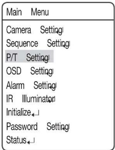
58 P/T Setting
65 OSD Setting
66 Alarm Setting
69 IR Illuminator
71 Initialize
72 Password setting
72 Status
TROUBLESHOOTING
73
73 Troubleshooting
PRODUCT SPECIFICATIONS
76
76 Product Specifications)
78 Dimensions
FEATURES
• A/F 37x Optical Zoom
The built-in 37x optical zoom lens with auto-focus is combined with a 16x digital zoom, providing a maximum of 592 zoom.
- Versatile protocols and coaxial communication
RS-422/485, Coaxial communication methods are supported.
- RS-422/485 (10 Protocol) : Auto Detected, SAMSUNG-T, SAMSUNG-E, Pelco (D/P), Panasonic, Vicon, Honeywell, AD, GE, BOSCH
- Coaxial communication: Pelco Coaxitron (Camera ID DIP switches (SW1) are all positioned to OFF)
- Wide Range Auto Security Functions
- Multiple Preset Function Saving : Up to 12 camera image properties can be saved individually to provide high quality pictures.
- Image Holding : When moving between presets in Group and Tour functions, using this Preset Freeze function holds the image status and helps the screen observer relieve visual fatigue.
- PTZ Trace : Patterns operated with the joystick can be saved and replayed by users.
- Swing : Using the Swing function commands the camera to move between 2 selected locations, monitoring the route.
- Group Search : Maximum 128 Preset positions are toured in order.
- Tour Search : Maximum 6 Group Search functions are toured in order.
- Digital Flip
The Digital Flip function is useful to monitor moving objects or people passing directly under the camera. When an object or a person passes directly under the camera, its tilt motor follows the object or person over 90 degrees to the other side of the tilt area without panning. The screen inversion starts to occur at 90 degrees or higher is digitally adjusted.
- Smart P/T
The Smart P/T function automatically adjusts the control speed of the Pan and Tilt functions according to the current zoom ratio. It is useful to adjust the functions manually for detailed controls when monitoring at high zoom ratios.
- Day & Night
With its daytime & nighttime switch and Sens-Up functions based on the ICR (Infrared Cut fi Iter Removal) method, the camera provides high quality pictures regardless of whether it is day or night.
- Sens-Up increases the CCD sensitivity by electrically extending the camera's exposure time.
- Day & Night enables you to select between color and B/W modes depending on the lighting conditions.
• Highly durable built-in housing
This IP66-rated built-in housing is easy to install, and protects the product from a full range of harsh outside conditions. The high performance built-in fan/heater enables the product to operate under extreme temperatures between -50^ 50^ .
- Preset Position Saving and Loading
Up to 255 preset positions can be set.
- Camera Backup
The configuration file of the camera can be saved for later use. This is useful when the camera or its install base are damaged or malfunctions occur.
- Area Masking
If a monitoring location includes a highly private area, the area can be selectively masked on the screen.
- IR Illuminator
You can use the IR Illuminator to configure the surveillance settings against a low contrast scene. The illuminator can be controlled in various ways within up to 100 meters in distance.
WHAT'S INCLUDED
Check if the following items are included in the product package.
| Appearance Item Name | Quantity Description | ||
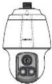 | Main Body 1 - | ||
 | CD Manual 1 Multilingual User Manual | ||
 | User Manual 1 English User Manual | ||
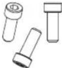 | Hexagon screw 3 | Used for attaching the installation base to the camera | |
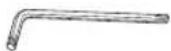 | L Wrench 1 | Used for fixing the installation base after attaching it to the camera |
Front Back
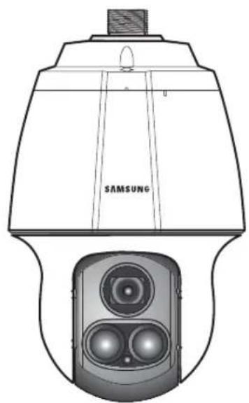
natural_image
Technical line drawing of a Samsung airship with two speakers (no text or symbols)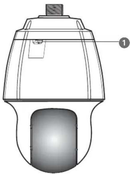
natural_image
Technical line drawing of a mechanical device with a cylindrical base and top component (no text or symbols)Bottom
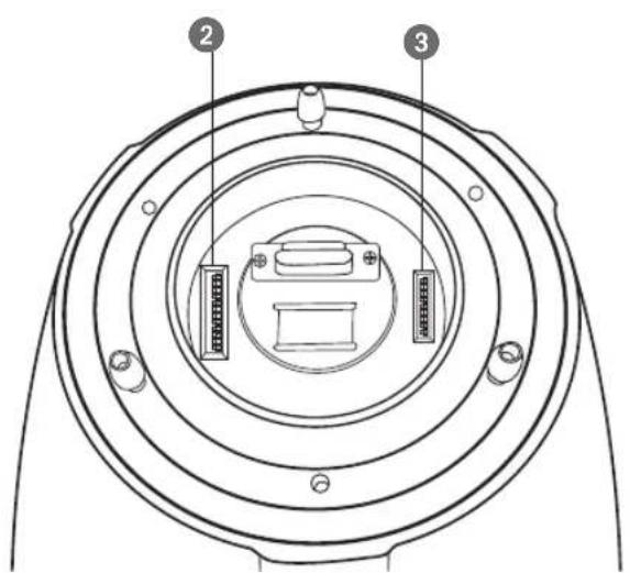
1 Safety Wire Holder
2 SW2: Communication DIP Switch
3 SW1: ID DIP Switch
※ For the DIP switch settings, please refer to the "Installing Your Camera" on Page 15\~19.
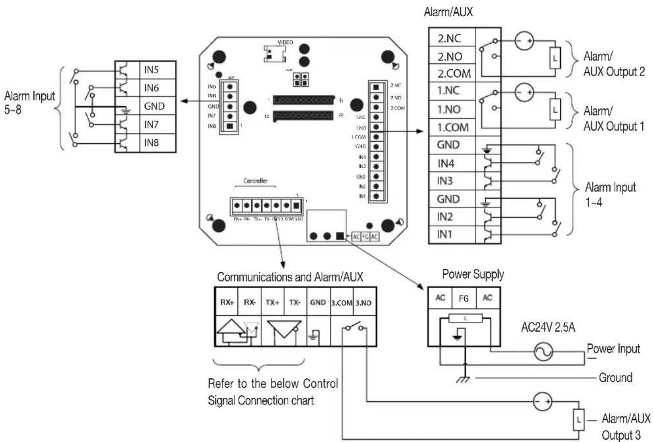
CAMERA WIRING INTERFACE BOARD
For the camera wiring, please refer to the picture below.
(When using coaxial communication, a separate control signal connection is not required.)
flowchart
graph TD
    A["Alarm Input 5~8"] --> B["IN5"]
    A --> C["IN6"]
    A --> D["GND"]
    A --> E["IN7"]
    A --> F["IN8"]
    B --> G["Controller"]
    C --> G
    D --> G
    E --> G
    F --> G
    G --> H["Communications and Alarm/AUX"]
    H --> I["Power Supply"]
    I --> J["AC24V 2.5A"]
    J --> K["Ground"]
    J --> L["Power Input"]
    L --> M["Alarm/AUX Output 1~4"]
    L --> N["Alarm/AUX Output 2"]
    L --> O["Alarm Input 5~8"]
    style A fill:#f9f,stroke:#333
    style H fill:#ccf,stroke:#333
    style I fill:#cfc,stroke:#333
    style J fill:#fcc,stroke:#333
    style K fill:#ffc,stroke:#333
    style L fill:#fcc,stroke:#333
    style M fill:#ffc,stroke:#333
    style N fill:#fcc,stroke:#333
Control Signal Connection

The max capacity of the Alarm OUT/AUX OUT ports are 30VDC/2A, 125VAC/0.5A, and 250VAC/0.25A, respectively.
■ Connecting the power connector and GND incorrectly to the NC/NO and COM ports may cause a short circuit and fire, damaging the camera.
■ Never use installation base for previous models (for SCP-2370/3370 and SPU-3750T/3700 models) with this product, it is not compatible with this product. Otherwise, applying power may lead to short circuit and result in fire or damage to the product.
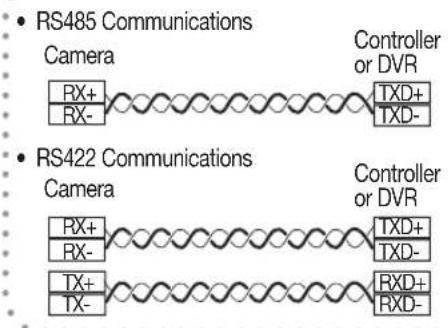
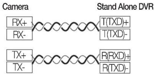
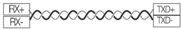
Connecting to the Samsung Techwin's "Stand Alone DVR"
- RS-485 :
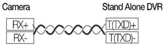
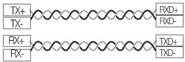
- RS-422 :
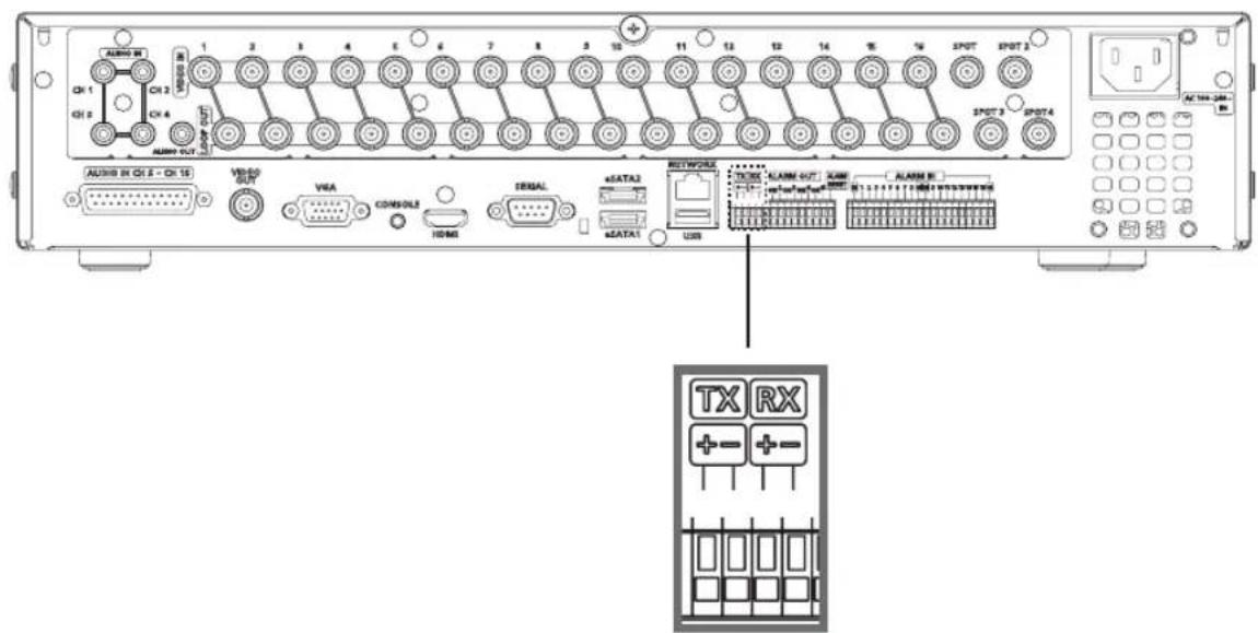
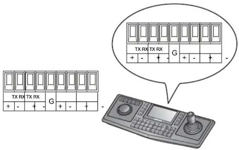
Connecting to the Samsung Techwin Controller SPC-6000
- RS-485 :
Camera
- RS-422 :
Camera
HOW TO SET UP PROTOCOLS AND ID DIP SWITCHES
You can control various settings of the camera system using the Communication and ID DIP switches. Before installing the product, please set up the DIP switches according to the installation environment.
- Detach the camera frame from the install base, and place the bottom of the frame toward you as shown in the picture below.
- Set the switches according to your installation environment. For more detailed setup information, please refer to the chart on the next page.
- The camera may malfunction if the switches are not fully turned On/Off; please double check the switches before finishing setup.
Communication Protocol DIP Switch(SW2)
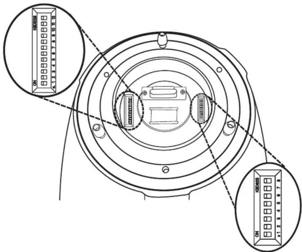
Camera ID DIP Switch(SW1)
COMMUNICATION PROTOCOL DIP SWITCH SETTINGS (SW2)
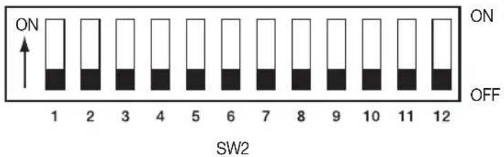
| SW2 Pin No. Purpose | |
| 1 ~ 4 Protocol Settings | |
| 5~6 Baud Rate Settings | |
| 7 Transfer Method (RS-485/422) Settings | |
| 8 Response Mode Settings | |
| 9~10 Backup Mode Settings | |
| 11~12 Termination Settings | |
Protocol Settings
Select a communication protocol for the camera.
| No | Protocol SW2-#1 SW2-#2 SW2-#3 SW2-#4 | |||
| 1 | Auto Detected OFF OFF OFF OFF | |||
| 2 | Samsung-T OFF OFF OFF ON | |||
| 3 | Samsung-E OFF OFF ON OFF | |||
| 4 | Pelco-D | OFF OFF ON | ON | |
| 5 | Pelco-P | OFF ON OFF | OFF | |
| 6 | Panasonic | OFF ON OFF | ON | |
| 7 | Vicon | OFF ON | ON OFF | |
| 8 | Honeywell | OFF | ON | ON |
| 9 | AD | ON OFF OFF | OFF | |
| 10 | GE | ON OFF OFF | ON | |
| 11 | Bosch | ON OFF ON | OFF |
Baud Rate Settings
Select the transfer speed of a selected communication protocol.
| No Baud Rate (BPS) SW2-#5 SW2-#6 | ||
| 1 2,400 ON ON | ||
| 2 4,800 ON OFF | ||
| 3 9,600 OFF OFF | ||
| 4 19,200 OFF ON |
Communication Method Settings
Select a communication method for the camera.
| Function ON OFF | |||
| SW2- #7 Transfer Mode Switch RS-422 (4Wire) RS-485 (2Wire) | |||
Communication Response Settings
Select a communication response method for the camera and controller: Response or No Response.
| Function ON OFF | |||
| SW2- #8 | Response Mode Switch | Response | No Response |
Termination Settings
To prevent the attenuation of communication signals between the camera and controller, the items at the end of line must be set up with the termination settings.
| Camera Input Position | SW2- #11 | SW2- #12 |
| Termination of Longest Path (RS-422) | ON | ON |
| Termination of Longest Path (RS-485) | ON | OFF |
| On the Path | OFF | OFF |
• Example of terminal setting
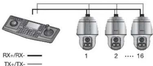
※ If using RS-422, SW2-#11: ON /SW2-#12: ON for camera 16
※ If using RS-485, SW2-#11: ON / SW2-#12: OFF for camera 16
Camera Backup Settings
These settings are useful when the camera or its install base are damaged or a malfunction has occurred.
When replacing the camera or its install base, you can transfer existing presets and sequence information to the replacement using these settings.
| Backup Function | SW2- #9 SW2- #10 | |
| Backup(IB→D) OFF OFF | ||
| Backup(D→IB) ON OFF | ||
| Backup Disable - ON |
- Backup(IB→D) : Enables transferring the current camera's sequence information to a new camera.
- Backup(D→IB): Enables transferring the current camera's sequence information to a new install base.
※ IB: Install base, D: Dome Camera
■ [Current Time] is not backed up from install base to camera.

For this model, all DIP switches are set to OFF by factory default. Each of the default settings will be grayed out in the applicable menu.
If you want to use a third-party controller for controlling the camera, contact us at the call center or visit our website for details.
■ AD Protocol Control Method
- Camera OSD On: 3+Auxiliary On
- Camera OSD Off: 3+Auxiliary Off
- Enter: IRIS Open
- ESC: IRIS Close
■ For more information about the protocols, refer to our official website.
http://www.samsungtechwin.com/
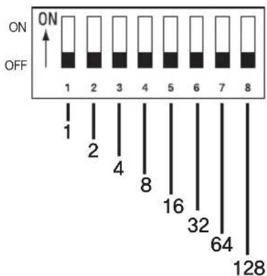
CAMERA ID DIP SWITCH SETTINGS (SW1)
Assign a unique number to each camera to identify itself from the others.
In coaxial communication systems, the camera will work normally only if the Camera ID DIP switches (SW1) are all positioned to OFF.
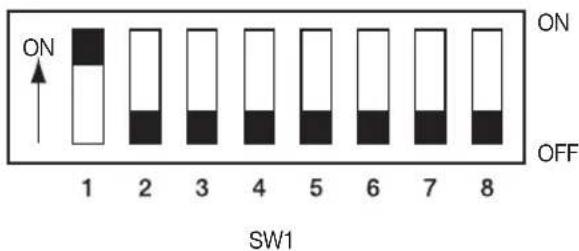
- The switch is set to "ID: 1" by default, and 7 switches other than switch 1 are all set to OFF.
- Each switch has a unique value, and the board ID is the sum of the values of the switches.
■ Refer to the example below for the board ID.
bar
| Position | Value | |---|---| | 1 | ON | | 2 | ON | | 3 | ON | | 4 | ON | | 5 | ON | | 6 | ON | | 7 | ON | | 8 | ON | | 1 | OFF | | 2 | OFF | | 4 | OFF | | 8 | OFF | | 16 | OFF | | 32 | OFF | | 64 | OFF | | 128 | Off || Example 1 | Example 2 Example 3 | |
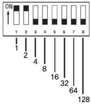 | 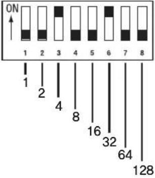 | 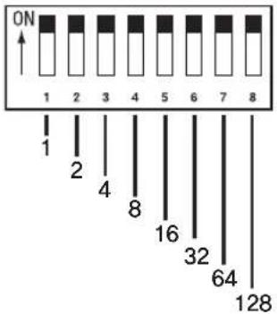 |
| 1+2 = 3 (Board ID = 3) 4+32 = 36 (Board ID = 36) | 1+2+4+8+16+32+64+128= 255 (Board ID = 255 ) | |

■ Use a unique ID for each Camera.
- Camera ID Chart
connection & installation
| ID SW1-#1 SW1-#2 SW1-#3 SW1-#4 SW1-#5 SW1-#6 SW1-#7 SW1-#8 | ||||||||
| 234 OFF ON OFF ON OFF ON ON ON | ||||||||
| 235 ON ON OFF ON OFF ON ON ON | ||||||||
| 236 OFF OFF ON ON OFF ON ON ON | ||||||||
| 237 ON OFF ON ON OFF ON ON ON | ||||||||
| 238 OFF ON ON ON OFF ON ON ON | ||||||||
| 239 ON ON ON ON OFF ON ON ON | ||||||||
| 240 OFF OFF OFF ON ON ON ON | ||||||||
| 241 ON OFF OFF OFF ON ON ON | ||||||||
| 242 OFF ON OFF OFF ON ON ON | ||||||||
| 243 ON ON OFF OFF ON ON ON | ||||||||
| 244 OFF OFF ON OFF ON ON ON | ||||||||
| 245 ON OFF ON OFF ON ON ON | ||||||||
| 246 OFF ON ON OFF ON ON ON | ||||||||
| 247 ON ON ON OFF ON ON ON | ||||||||
| 248 OFF OFF OFF ON ON ON ON | ||||||||
| 249 ON OFF OFF ON ON ON ON | ||||||||
| 250 OFF ON OFF ON ON ON ON | ||||||||
| 251 ON ON OFF ON ON ON ON | ||||||||
| 252 OFF OFF ON ON ON ON ON | ||||||||
| 253 ON OFF ON ON ON ON ON | ||||||||
| 254 OFF ON ON ON ON ON ON | ||||||||
| 255 ON ON ON ON ON ON ON | ||||||||
PREPARING ADAPTER AND CABLES
- Power Adapter
Power adapter has the capacity of AC24V 6A.

natural_image
Illustration of a portable electronic device with cables and an AC outlet (no text or symbols)- Video Cable
The camera's video output port is connected to the monitor with a BNC coaxial cable, shown below: If the distance between the camera and the monitor exceeds the recommended maximum, please use an auxiliary video amp.
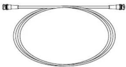
natural_image
Pure diagram of a coiled cable with two connectors (no text or symbols)| Distance | Recommended Cable Specification |
| 300m 4C2V(RG-59/U) | |
| 450m 5C2V(RG-6/U) | |
| 600m 7C2V(RG-11/U) |

If the camera is controlled through coaxial communication, please use a video amp intended for coaxial communications. Regular video amps do not transfer coaxial signals.
• Communications Cable
For the camera to communicate with the controller, a RS-485/422 communications line is required. To ensure the quality of long distance communication and the accuracy of the overall communication it is recommended using a twisted pair cable such as UTP.
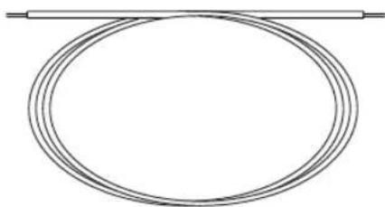
natural_image
Pure diagram of two parallel lines intersecting a central oval shape (no text or symbols)
Depending on the camera's environment, the communications distance may vary.
■ Neither the video nor communications cable is enclosed with the camera.
PRODUCT CONFIGURATIONS
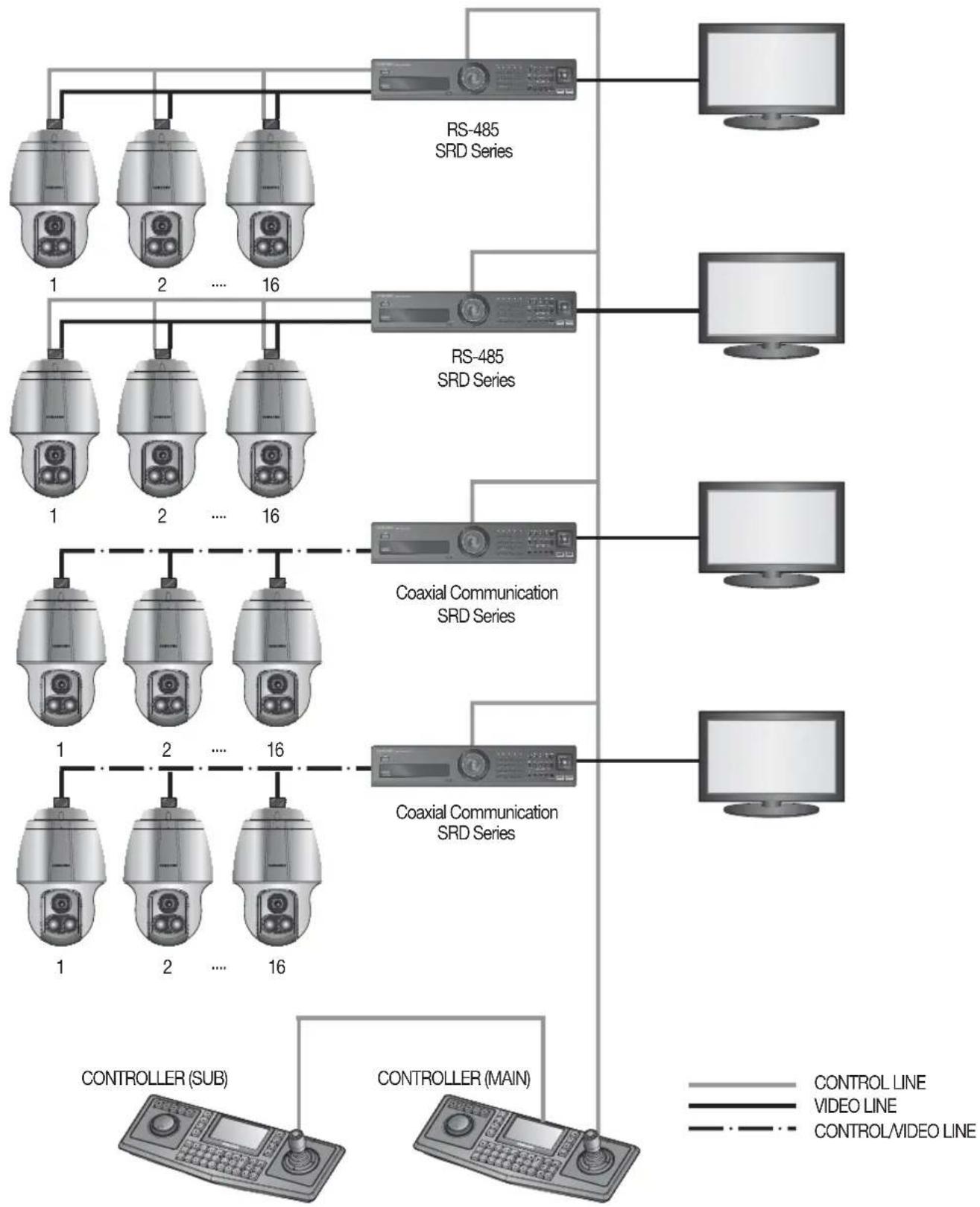
flowchart
graph TD
    subgraph_RS-485_SRD_Series["RS-485 SRD Series"]
        A1["1"] --> RS-485_SRD_Series
        A2["2"] --> RS-485_SRD_Series
        A3["...."] --> RS-485_SRD_Series
        A16["16"] --> RS-485_SRD_Series
    end
    subgraph_Coaxial_Communication_SRD_Series["Coaxial Communication SRD Series"]
        B1["1"] --> Coaxial_Communication_SRD_Series
        B2["2"] --> Coaxial_Communication_SRD_Series
        B3["...."] --> Coaxial_Communication_SRD_Series
        B16["16"] --> Coaxial_Communication_SRD_Series
    end
    subgraph_Controller_Sub["CONTROLLER (SUB)"]
        C1["1"] --> Controller_Sub
        C2["2"] --> Controller_Sub
        C3["...."] --> Controller_Sub
        C16["16"] --> Controller_Sub
    end
    subgraph Controller(Main["CONTROLLER (MAIN)"]
        D1["1"] --> Controller(Main)
        D2["2"] --> Controller(Main)
        D3["...."] --> Controller(Main)
        D16["16"] --> Controller(Main)
    end
    RS-485_SRD_Series --> PC1["PC1"]
    RS-485_SRD_Series --> PC2["PC2"]
    RS-485_SRD_Series --> PC3["PC3"]
    RS-485_SRD_Series --> PC4["PC4"]
    RS-485_SRD_Series --> PC5["PC5"]
    RS-485_SRD_Series --> PC6["PC6"]
    RS-485_SRD_Series --> PC7["PC7"]
    RS-485_SRD_Series --> PC8["PC8"]
    RS-485_SRD_Series --> PC9["PC9"]
    RS-485_SRD_Series --> PC10["PC10"]
    RS-485_SRD_Series --> PC11["PC11"]
    RS-485_SRD_Series --> PC12["PC12"]
    RS-485_SRD_Series --> PC13["PC13"]
    RS-485_SRD_Series --> PC14["PC14"]
    RS-485_SRD_Series --> PC15["PC15"]
    RS-485_SRD_Series --> PC16["PC16"]
    RS-485_SRD_Series --> PC17["PC17"]
    RS-485_SRD_Series --> PC18["PC18"]
    RS-485_SRD_Series --> PC19["PC19"]
    RS-485_SRD_Series --> PC20["PC20"]
    RS-485_SRD_Series --> PC21["PC21"]
    RS-485_SRD_Series --> PC22["PC22"]
    RS-485_SRD_Series --> PC23["PC23"]
    RS-485_SRD_Series --> PC24["PC24"]
    RS-485_SRD_Series --> PC25["PC25"]
    RS-485_SRD_Series --> PC26["PC26"]
    RS-485_SRD_Series --> PC27["PC27"]
    RS-485_SRD_Series --> PC28["PC28"]
    RS-485_SRD_Series --> PC29["PC29"]
    RS-485_SRD_Series --> PC30["PC30"]
    RS-485_SRD_Series --> PC31["PC31"]
    RS-485_SRD_Series --> PC32["PC32"]
    RS-485_SRD_Series --> PC33["PC33"]
    RS-485_SRD_Series --> PC34["PC34"]
    RS-485_SRD_Series --> PC35["PC35"]
    RS-485_SRD_Series --> PC36["PC36"]
    RS-485_SRD_Series --> PC37["PC37"]
    RS-485_SRD_Series --> PC38["PC38"]
    RS-485_SRD_Series --> PC39["PC39"]
    RS-485_SRD_Series --> PC40["PC40"]
    RS-485_SRD_Series --> PC41["PC41"]
    RS-485_SRD_Series --> PC42["PC42"]
    RS-485_SRD_Series --> PC43["PC43"]
    RS-485_SRD_Series --> PC44["PC44"]
    RS-485_SRD_Series --> PC45["PC45"]
    RS-485_SRD_Series --> PC46["PC46"]
    RS-485_SRD_Series --> PC47["PC47"]
    RS-485_SRD_Series --> PC48["PC48"]
    RS-485_SRD_Series --> PC49["PC49"]
    RS-485_SRD_Series --> PC50["PC50"]
    RS-485_SRD_Series --> PC51["PC51"]
    RS-485_SRD_Series --> PC52["PC52"]
    RS-485_SRD_Series --> PC53["PC53"]
    RS-485_SRD_Series --> PC54["PC54"]
    RS-485_SRD_Series --> PC55["PC55"]
    RS-485_SRD_Series --> PC56["PC56"]
    RS-485_SRD_Series --> PC57["PC57"]
    RS-485_SRD_Series --> PC58["PC58"]
    RS-485_SRD_Series --> PC59["PC59"]
    RS-485_SRD_Series --> PC60["PC60"]
    RS-485_SRD_Series --> PC61["PC61"]
    RS-485_SRD_Series --> PC62["PC62"]
    RS-485_SRD_Series --> PC63["PC63"]
    RS-485_SRD_Series --> PC64["PC64"]
    RS-485_SRD_Series --> PC65["PC65"]
    RS-485_SRD_Series --> PC66["PC66"]
    RS-485_SRD_Series --> PC67["PC67"]
    RS-485_SRD_Series --> PC68["PC68"]
    RS-485_SRD_Series --> PC69["PC69"]
    RS-485_SRD_Series --> PC70["PC70"]
    RS-485_SRD_Series --> PC71["PC71"]
    RS-485_SRD_Series --> PC72["PC72"]
    RS-485_SRD_Series --> PC73["PC73"]
    RS-485_SRD_Series --> PC74["PC74"]
    RS-485_SRD_Series --> PC75["PC75"]
    RS-485_SRD_Series --> PC76["PC76"]
    RS-485_SRD_Series --> PC77["PC77"]
    RS-485_SRD_Series --> PC78["PC78"]
    RS-485_SRD_Series --> PC79["PC79"]
    RS-485_SRD_Series --> PC80["PC80"]
    RS-485_SRD_Series --> PC81["PC81"]
    RS-485_SRD_Series --> PC82["PC82"]
    RS-485_SRD_Series --> PC83["PC83"]
    RS-485_SRD_Series --> PC84["PC84"]
    RS-485_SRD_Series --> PC85["PC85"]
    RS-485_SRD_Series --> PC86["PC86"]
    RS-485_SRD_Series --> PC87["PC87"]
    RS-485_SRD_Series --> PC88["PC88"]
    RS-485_SRD_Series --> PC89["PC89"]
    RS-485_SRD_Series --> PC90["PC90"]
    RS-485_SRD_Series --> PC91["PC91"]
    RS-485_SRD_Series --> PC92["PC92"]
    RS-485_SRD_Series --> PC93["PC93"]
    RS-485_SRD_Series --> PC94["PC94"]
    RS-485_SRD_Series --> PC95["PC95"]
    RS-485_SRD_Series --> PC96["PC96"]
    RS-485_SRD_Series --> PC97["PC97"]
    RS-485_SRD_Series --> PC98["PC98"]
    RS-485_SRD_Series --> PC99["PC99"]
PREPARING & INSTALLING CAMERA BRACKET
For installation guidelines for brackets and housings, refer to the installation manual that is enclosed with the bracket or housing.
◆ Available Bracket Models
| Model Item | |
| SBP-300WM1 | Wall Mount |
| SBP-300WM | |
| SBP-300CM Ceiling Mount | |
| SBP-300LM Parapet Mount | |
| SBP-300KM Corner Mount | |
| SBP-300PM Pole Mount |

See "Optional Accessories for Installation" on the next page for the appearance of each bracket (unbundled).
OPTIONAL ACCESSORIES FOR INSTALLATION
For your easier installation, you can purchase appropriate optional accessories available.
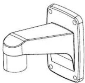
- If installing the camera on the wall
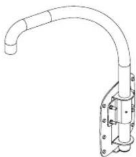
• Wall mount (SBP-300WM1)
natural_image
Technical line drawing of a mechanical bracket or bracket (no text or symbols)• Wall mount (SBP-300WM)
natural_image
Technical line drawing of a pipe fitting with flanged base (no text or symbols)- If installing the camera on the ceiling
• Ceiling Mount (SBP-300CM)
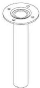
natural_image
Technical line drawing of a cylindrical mechanical part with flange and bolt holes (no text or symbols)- If installing the wall mount (SBP-300WM/SBP-300WM1) on a pole with a diameter of at least 80mm
- Pole Mount (SBP-300PM)
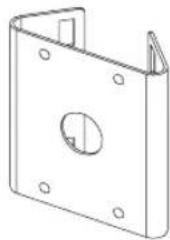
natural_image
Technical line drawing of a metal bracket with mounting holes and a central hole (no text or symbols)- If installing the wall mount (SBP-300WM/SBP-300WM1) on a corner of the wall
• Corner Mount (SBP-300KM)
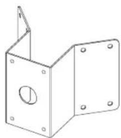
natural_image
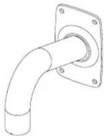
Technical line drawing of a metal bracket with mounting holes and a circular hole (no text or symbols)- If installing on a building rooftop
• Parapet Mount (SBP-300LM)
natural_image
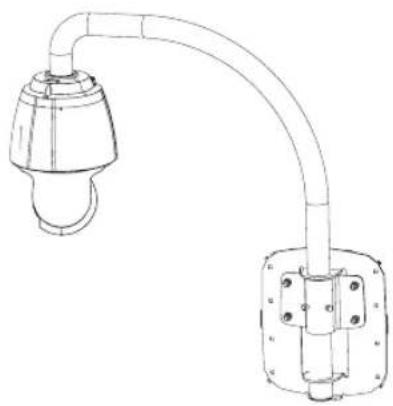
Technical line drawing of a curved pipe fitting with mounting bracket (no text or symbols)- Bracket Mounting
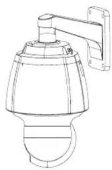
natural_image
Line drawing of a security camera with mounted arm and dome (no text or symbols)Wall mount (SBP-300WM1)
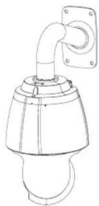
natural_image
Technical line drawing of a pipe fitting with mounting flange (no text or symbols)Wall mount (SBP-300WM)
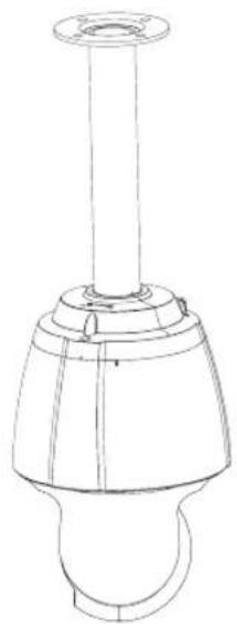
natural_image
Technical line drawing of a mechanical component with a cylindrical shaft and flange (no text or symbols)Ceiling Mount (SBP-300CM)
natural_image
Technical line drawing of a mechanical or electrical component with a curved pipe and mounting bracket (no text or symbols)Parapet Mount (SBP-300LM)
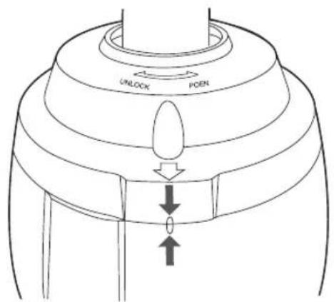
◆ Fixing the installation base to the bracket
- Fix the base with the bracket by turning it clockwise.
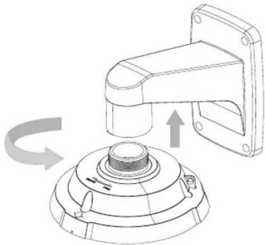
natural_image
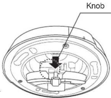
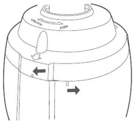
Technical line drawing of a mechanical component with a rotating arrow indicating rotation (no text or symbols)- Hold the bottom latch of the installation base and gently press it down as shown. Please refer to the "Camera Wiring Interface Board" on page 12, connect the wires.

-
Do not connect the camera to a power outlet until the installation is complete. Supplying power while the installation is in progress may cause fire or damage the product.
■ Never use installation base for previous models (for SCP-2370/3370 and SPU-3750T/3700 models) with this product, it is not compatible with this product. Otherwise, applying power may lead to short circuit and result in fire or damage to the product. -
Connect the camera safety wire to the installation base.
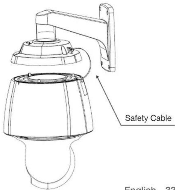
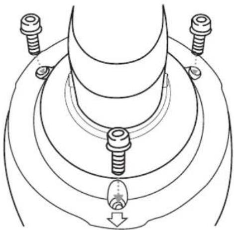
- Assembling the Camera and Installation Base Assemble the installation base and camera by matching the installation direction guides.
- Attach Camera Turn the camera frame counterclockwise until the protrusions on the camera frame and installation base become matched perfectly.
- Secure Camera and Installation Base As shown in the picture below, secure the installation base and camera using 3 hexagon screws.
natural_image
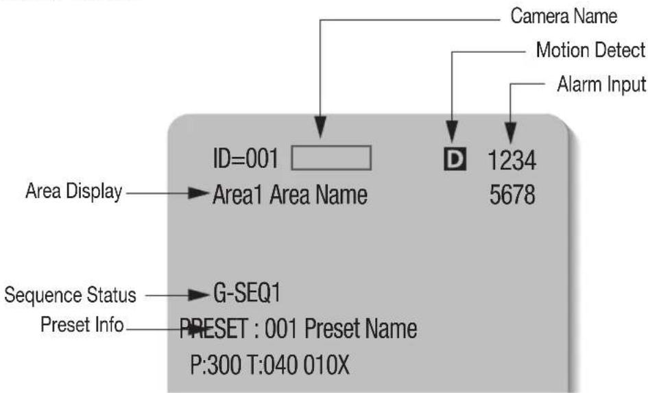
Technical line drawing of a mechanical component with threaded fasteners and a base, no text or symbols presentINTERFACE SYMBOLS
• Motion Detection Standby/Operation Display :
When in standby mode, the “D” in the upper right of the screen blinks and then changes to “if motion is detected.
• Alarm Input Port Status Display :
①", ②", ③", ④", ⑤", ⑥", ⑦", and ⑧" in the upper right of the screen blink.
- Current Alarm Port Display According to Input Alarm Ports(Priority):
Only one of "⚡1", "⚡2", "⚡3", "⚡4", "⚡5", "⚡6", "⚡7", "⚡8" in the upper right of the screen blinks.
- Preset Number Display Settings :
* : If a preset number is already available
'H': If a preset location is the camera's home position
• PTZ Function Screen :
- Preset Number Setting Screen :
Preset Setting
Preset=011* (1\~255)
USING AND SETTING THE MENUS
OSD (On-screen Display) Indicators
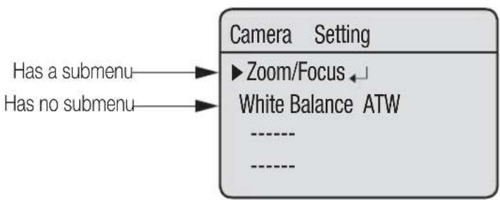
flowchart
graph TD
    A["Camera Setting"] --> B["Zoom/Focus"]
    B --> C["White Balance ATW"]
    D["Has a submenu"] --> B
    E["Has no submenu"] --> B
※ For a mode with “” next to it, you can press “Enter” to move to a sub menu.
Operating Your Camera
- Panning and Tilting :
Use the joystick of the controller or its direction buttons.
- Controlling Zoom :
Move the joystick clockwise (Tele) or counterclockwise (Wide), or use the zoom buttons.
- Accessing Screen Menus:
Press the Menu or OSD button on the controller.

For more detailed information about controls when using a third party controller or a DVR, refer to the user's manual of that product
OSD Commands, Function Chart, and Menu Controls (Applied to Samsung T/Samsung E protocol)
This camera can be operated by using two methods: Using hot keys on its dedicated controller, or accessing the OSD (On Screen Display) on the video output.
The OSD menu commands are as follows:
| Command Function | |
| Move the joystick up/down/left/right Moves | the OSD menus up/down/left/right, respectively. |
| Enter/Focus Far Selects a menu and allows access to the sub menus. | |
| ESC/Focus Near Cancels a command and moves back to an upper-level menu. | |
OSD Menu Chart
You can have an overall view of the menu structure. For more information, refer to the applicable page or section in the manual.
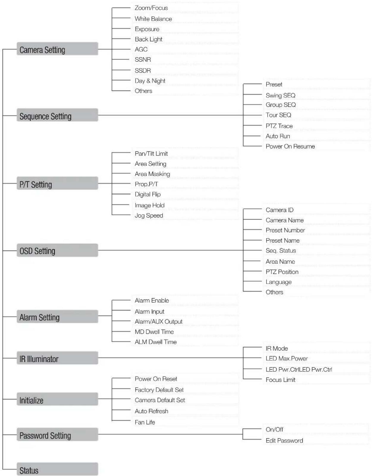
flowchart
graph TD
    A["Camera Setting"] --> B["Zoom/Focus"]
    A --> C["White Balance"]
    A --> D["Exposure"]
    A --> E["Back Light"]
    A --> F["AGC"]
    A --> G["SSNR"]
    A --> H["SSDR"]
    A --> I["Day & Night"]
    A --> J["Others"]
    K["Sequence Setting"] --> L["Preset"]
    K --> M["Swing SEQ"]
    K --> N["Group SEQ"]
    K --> O["Tour SEQ"]
    K --> P["PTZ Trace"]
    K --> Q["Auto Run"]
    K --> R["Power On Resume"]
    S["P/T Setting"] --> T["Pan/Tilt Limit"]
    S --> U["Area Setting"]
    S --> V["Area Masking"]
    S --> W["Prop.P/T"]
    S --> X["Digital Flip"]
    S --> Y["Image Hold"]
    S --> Z["Jog Speed"]
    AA["OSD Setting"] --> AB["Camera ID"]
    AA --> AC["Camera Name"]
    AA --> AD["Preset Number"]
    AA --> AE["Preset Name"]
    AA --> AF["Seq. Status"]
    AA --> AG["Area Name"]
    AA --> AH["PTZ Position"]
    AA --> AI["Language"]
    AA --> AJ["Others"]
    AK["Alarm Setting"] --> AL["Alarm Enable"]
    AK --> AM["Alarm Input"]
    AK --> AN["Alarm/AUX Output"]
    AK --> AO["MD Dwell Time"]
    AK --> AP["ALM Dwell Time"]
    AQ["IR Illuminator"] --> AR["IR Mode"]
    AQ --> AS["LED Max.Power"]
    AQ --> AT["LED Pwr.Ctrl LED Pwr.Ctrl Focus Limit"]
    AU["Initialize"] --> AV["Power On Reset"]
    AU --> AW["Factory Default Set"]
    AU --> AX["Camera Default Set"]
    AU --> AY["Auto Refresh"]
    AU --> AZ["Fan Life"]
    BA["Password Setting"] --> BB["On/Off"]
    BA --> BC["Edit Password"]
    BD["Status"] --> BE
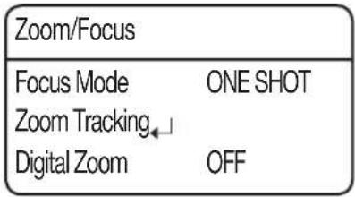
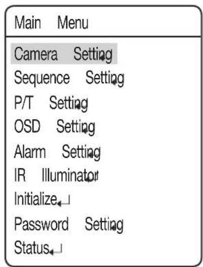
CAMERA SETUP
Zoom and Focus Settings
- Focus Mode
-AUTO: Performs continuous auto-focus.
- MANUAL : Changes the camera mode to Manual Focus.
-ONE SHOT: Auto-focuses the camera once after the Pan, Tilt, or Zoom function is used.
- Zoom Tracking
Through this menu you can set up the camera's focus mode when zooming.
- Mode
• Auto : Auto-focuses when zooming.
- Tracking : Focuses manually when zooming.
- Off: Disable the focus modes when zooming. (Full manual mode)
- Speed
- Slow/Medium/Fast: Adjusts the zooming speed.
| Fast Medium Slow | |||
| 37x 2.5 sec 3.1 | sec 5.6 sec | ||
- Digital Zoom
Enables the maximum digital zoom.
Setting the digital zoom to 2x\~16x provides a total zoom of 592x.

■ Unlike the optical zoom, the graphics quality of the digital zoom decreases as its zoom ratio increases.
■ The auto-focus function may not operate normally under the following conditions :
- When background illumination is low
- While Slow-Shutter is in operation
- If the zoom level is set too high
- When background illumination is too high
- If a long distance object and a close distance object appear together within a monitoring area
- If there is no contrast, e.g. the sky or a wall
- If the camera is facing a thin horizontal line
■ Auto Focus focuses on an object in the center of the screen; objects around the screen edges may not be properly in focus.
If the IR indicator turns on and the zoom factor is at least x21, the focus mode will be set to Manual regardless of the focus mode settings.
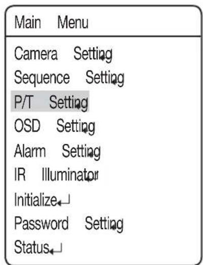
| Main Menu |
| Camera Setting |
| Sequence Setting |
| P/T Setting |
| OSD Setting |
| Alarm Setting |
| IR Illuminator |
| Initialize |
| Password Setting |
| Status |

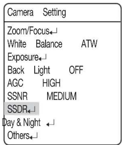
| Camera Setting | |
| Zoom/Focus← | |
| White Balance ATW | |
| Exposure← | |
| Back Light OFF | |
| AGC HIGH | |
| SSNR MEDIUM | |
| SSDR← | |
| Day & Night ← | |
| Others← |

 |
The White Balance menu adjusts the balance of the screen colors under different lighting conditions.
- ATW: Adjusts the screen color automatically. (Color Temperature: 1800\~10500°K)
- ATW(IN) : Adjusts the screen color to be optimal in an indoor environment. (Color Temperature:4500\~8500°K)
- ATW(OUT) : Adjusts the screen color to be optimal in an outdoor environment. (Color Temperature:1700\~11000°K)
- AWC: To obtain the optimal condition for the current lighting, put the focus of the camera onto to a white paper and press the SET button. If the lighting environment changes, you should readjust the settings accordingly.
- MANUAL : Enables customization of the Red and Blue gains.
Main Menu
Camera Setting
Sequence Setting
P/T Setting
OSD Setting
Alarm Setting
IR Illuminator
Initialize
Password Setting
Status

Camera Setting
Zoom/Focus
White Balance ATW
Exposure
Back Light OFF
AGC HIGH
SSNR MEDIUM
SSDR
Day & Night
Others

■ White Balance may not work properly under the following conditions.
① When the color temperature of the environment surrounding the subject is out of the control range.(e.g. Clear sky or sunset)
② When the ambient illumination of the subject is dim.
③ If the camera is directed towards a fluorescent light or is installed in a place where illumination changes dramatically, White Balance adjustments may not deliver consistent results.
Exposure
The Exposure settings control the camera's exposure level.
● Brightness : Adjusts the screen brightness.
(Over 50: Brighter, Under 50: Darker)
- Iris
-AUTO : Automatically adjusts the exposure level.
- MANUAL : Enables manual adjustment of the exposure level.
(F1.6\~Close: 18 levels)
- Shutter: Controls the camera's electronic shutter.
----: The shutter speed is fixed at 1/60 for NTSC and 1/50 for PAL. Operates when Iris is on the Auto Mode.
- ESC : Adjusts the shutter speed automatically according to the screen brightness. Operates when the Iris is in Manual Mode.
-A.FLK : Select this setting when you experience picture flickering. Flickering can happen when artificial lighting frequencies clash with camera frame rates.
- MANUAL : Enables manual adjustment of the shutter speed.
- Sens-Up
-AUTO: Automatically detects light levels and maintains a clear picture at night or under low-light conditions.
▶ Sens-Up Limit : Adjusts to the maximum-powered zoom per frame.
Main Menu
Camera Setting
Sequence Setting
P/T Setting
OSD Setting
Alarm Setting
IR Illuminator
Initialize
Password Setting
Status

Camera Setting
Zoom/Focus
White Balance ATW
Exposure
Back Light OFF
AGC HIGH
SSNR MEDIUM
SSDR
Day & Night
Others

Exposure
Brightness 050
Iris AUTO
Shutter ---
Sens-Up AUTO


For optimal performance of the A.FLK mode, avoid using the mode in conjunction with Backlight.
While the Internal Sync mode is in effect, setting the shutter to ‘---’ and facing the camera directly to a bright light source may cause poor camera performance.
■ Sens-Up is disabled when the shutter is in Manual or A. FLK mode.
If the gain mode is set to "Off" or "Manual", the Sens-Up function will not be activated.
Back Light
The Backlight function is incorporated in the W-V DSP chip, developed by Samsung Techwin, which, unlike the old models, provides a sharp image of both object and background against a severe counter-light condition.
- Back Light Mode
- OFF : Disables the Backlight mode.
- HLC : Activates the High Light Compensation mode. (See "HLC Setting" on the next page for details.)
- BLC : Activates a user defined backlight compensation mode.
| Main Menu |
| Camera Setting |
| Sequence Setting |
| P/T Setting |
| OSD Setting |
| Alarm Setting |
| IR Illuminator |
| Initialize↓ |
| Password Setting |
| Status↓ |

| Camera Setting | |
| Zoom/Focus← | |
| White Balance ATW | |
| Exposure← | |
| Back Light OFF | |
| AGC HIGH | |
| SSNR MEDIUM | |
| SSDR← | |
| Day & Night ← | |
| Others← |
HLC Setting
The HLC settings selectively eliminates high lights in a limited environment such as the entrance to an apartment parking lot or gas station, and is useful to detect a small objects like car license plates.
| HLC Setting | ||
| Level | MEDIUM | |
| Mask | Tone | 07 |
HLC is disabled during the daytime. While monitoring nigh time car traffic, if car headlights reflects too much bright light on the screen, the camera automatically eliminates the headlamp lights and adjusts the color of the license plate accordingly.
- Level : Adjusts the HLC sensitivity level.
- Mask Tone : Adjusts the mask color on the high lighted area.

■ Even if HLC is on, car license plates may not be detectable depending on the location and angle of the camera as well as the lighting condition.
■ The HLC function will be disabled while using Digital Zoom, Freeze or Stabilizer.
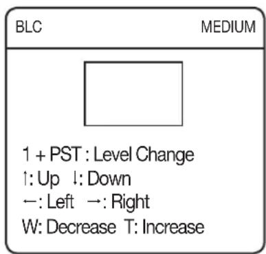
BLC Setting
You can selectively choose a screen area to see objects within the area more clearly than others.
- Four-direction Joystick Controls : Moving the joystick in all four directions—upward, downward, left, and right—adjusts the location and size of a selected area.
-Zoom Control :
- Zoom Tele : Enlarges the size of a selected area.
- Zoom Wide : Reduces the size of a selected area.
AGC(Auto Gain Control)
AGC (Automatic Gain Control) adjusts the camera's gain control and the screen brightness if the camera has captured an object under low-light conditions.
- OFF:
AGC does not function.
- LOW/MEDIUM/HIGH:
As the level increases to HIGH, brighter the captured screen in a dark lighting.
- MANUAL:
AGC can be fine tuned by adjusting the level (5dB \~ 41dB).
| Main Menu |
| Camera Setting |
| Sequence Setting |
| P/T Setting |
| OSD Setting |
| Alarm Setting |
| IR Illuminator |
| Initialize |
| Password Setting |
| Status |

| Camera Setting | |
| Zoom/Focus← | |
| White Balance ATW | |
| Exposure← | |
| Back Light OFF | |
| AGC HIGH | |
| SSNR MEDIUM | |
| SSDR← | |
| Day & Night ← | |
| Others← |

If the IR mode is set to "DAY/NIGHT", you can set the gain mode only to one of "LOW/MEDIUM/HIGH".
SSNR(Samsung Super Noise Reduction)
SSNR significantly reduces the amount of low luminance noise.
- OFF : Disables the noise reduction function.
- LOW: Reduces only a small amount of noise, but generates almost no afterimage.
- MEDIUM : The most commonly used mode. Reduces a suitable amount of noise while generating a subtle afterimage.
- HIGH : Reduces noise signifi cantly, but generates obvious afterimages.
| Main Menu |
| Camera Setting |
| Sequence Setting |
| P/T Setting |
| OSD Setting |
| Alarm Setting |
| IR Illuminator |
| Initialize↓ |
| Password Setting |
| Status↓ |

| Camera Setting | |
| Zoom/Focus← | |
| White Balance ATW | |
| Exposure← | |
| Back Light OFF | |
| AGC HIGH | |
| SSNR MEDIUM | |
| SSDR← | |
| Day & Night ← | |
| Others← |

■ SSNR is not available if AGC is set to OFF or MANUAL.
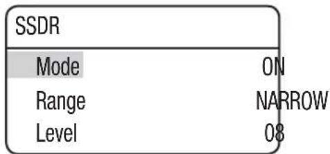
SSDR(Samsung Super Dynamic Range)
SSDR illuminates darker spots of an image while retaining the same light level for brighter spots to even out the overall brightness of the image with high contrast between bright and dark spots.
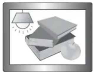
natural_image
Illustration of stacked books with a hanging lamp and an apple, no text or symbols presentSSDR ON
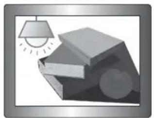
natural_image
Illustration of stacked books with a hanging lamp and a sun, no text or symbols presentSSDR OFF
- Mode : Enables or disables SSDR.
- Range : Defines a range of SSDR.
- Level : Changes the contrast between bright and dark spots by the level.


Day & Night
The Day & Night function allows the camera to switch between the Color and B/W modes.
- MODE
- AUTO : Operates in Color mode most times, and switches to B/W mode if a low light level is detected during nighttime.
- COLOR : Operates in Color mode at all times.
- B/W : Operates in B/W mode at all times. By using the Burst On/Off sub menu, burst signals can be retained or disabled.
※ If the camera is in B/W mode and connected to equipment that requires external sync through burst signals, set the Burst On/Off option to "On".
- Duration :
- The camera's light sensitivity is adjustable as in the chart below. The camera's ambient light diversion performance may vary depending on its environment.
| Color→B/W B/W | → Color | |
| FAST 2.6Lux | 4.2Lux | |
| SLOW 1.2Lux | 6.0Lux |
- Dwell Time :
- The duration of both the lighting conditions can be customized to let the camera divert between the daytime and nighttime settings.
| Main Menu |
| Camera Setting |
| Sequence Setting |
| P/T Setting |
| OSD Setting |
| Alarm Setting |
| IR Illuminator |
| Initialize↓ |
| Password Setting |
| Status↓ |

| Camera Setting | |
| Zoom/Focus← | |
| White Balance ATW | |
| Exposure← | |
| Back Light OFF | |
| AGC HIGH | |
| SSNR MEDIUM | |
| SSDR← | |
| Day & Night← | |
| Others← |

| Day/Night | |
| Mode | AUTO |
| Duration | SLOW |
| Dwell Time | 05 SEC |

■ Auto mode is not available if AGC is set to OFF or MANUAL.
■ Using B/W mode under sunlight or a halogen lamp may decrease the focusing performance.
As long as the indicator of the IR light turns on, the camera will be set to B/W mode automatically.
■ If the IR light is set to Day/Night mode, the mode will switch to Auto automatically.
If the IR illuminator is set to SENSOR or TIMED, it will switch to Day or Night mode depending on the sensor or time.
- Sync: Select Internal or Line Lock.
- INTERNAL : Synchronizes the camera's output timing to the internal crystal.
- LINE LOCK : Synchronizes the camera's output timing to the AC adapter power to synchronize multiple cameras. This option is useful when using a switch such as Matrix Switcher.
LINE LOCK PHASE : Enables setting the adapter's synchronization phase between 0 and 359^ .
- Image Adj :
- Sharpness : Sharpens outlines of an image.
- Color : Adjusts the color density of an image.
- Freeze: Stops or reanimates an image.
- Stabilizer: The Stabilizer compensates for any small movements of the camera caused by the wind and other such events

■ The Stabilizer uses the digital zoom and may cause low picture quality.
■ The Stabilizer is disabled if the ambient light is too low.
■ The Stabilizer is disabled if the field of view has very low or no contrast, e.g. The sky or a white wall.
If you are using the Freeze function, the stabilizer function will be disabled.
Main Menu
Camera Setting
Sequence Setting
P/T Setting
OSD Setting
Alarm Setting
IR Illuminator
Initialize
Password Setting
Status

Camera Setting
Zoom/Focus
White Balance ATW
Exposure
Back Light OFF
AGC HIGH
SSNR MEDIUM
SSDR
Day & Night
Others

Others
Sync INTERNAL
Image Adj
Freeze OFF
Stabilizer OFF
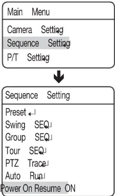
Sequence Setting
Preset
This function enables the memorization of a selected location and activates the Pan, Tilt, and Zoom functions at that location. Saved locations can be recalled using the Preset Execute command.
- Setting Up Preset Numbers :
Selecting the Preset Setting menu brings up a screen as shown below. Move the joystick in all four directions to select the desired number.
Selecting a preset number and pressing the Enter key redirects the menu to the screen shown below.
Using the joystick, adjust the location of the Pan and Tilt functions and then set the Zoom and Focus command.
In Preset mode, the zooming focus can be controlled only by the zoom command.
| Preset Setting | |
| 1+PST:ZOOM | 2+PST:FOCUS |
| Main Menu |
| Camera SettingSequence SettingP/T SettingOSD SettingAlarm SettingIR IlluminatorInitializePassword SettingStatus |

| Sequence Setting |
| Preset← |
| Swing SEQ |
| Group SEQ |
| Tour SEQ |
| PTZ Trace |
| Auto Run |
| Power On Resume ON |

| Preset |
| Setting↓ |
| Edit↓ |
| Home Position OFF |
| Execute↓ |
| Clear↓ |
| Status↓ |
PTZF Setting
- If you open the PTZF setup menu, you will see the following window. You can use the joystick to select a desired number.
- Select a preset number and press ENTER. You will move to the setup screen.
Using the joystick, adjust the location of the Pan and Tilt functions and then set the Zoom and Focus command.
In Preset mode, the zooming focus can be controlled only by the zoom command.
For switching modes, refer to the menu bar in the bottom.
Edit
With this feature, you can edit or save the video-related settings for each preset of the camera.
- PTZ : Recalls saved locations using the Preset Settings command.
- Focus : Refer to the section entitled Setting Up Your Camera.
- Brightness : Refer to the section entitled Setting Up Your Camera.
- Iris : Refer to the section entitled Setting Up Your Camera.
- Back Light : Refer to the section entitled Setting Up Your Camera.
- Day & Night : Refer to the section entitled Setting Up Your Camera.
- After Action : Enables setting up an automatic action after the camera arrives at a selected preset location.
- MD : Commands the camera to perform the Motion Detection function. If Focus mode is set to Auto, the MD function may not work properly in a challenging environment.
- OFF : Select this when no action is desired.
- Others: You can set AGC, Stabilizer, SSNR, SSDR, Shutter, Sens-Up and White Balance functions. For terms related to settings, refer to the camera settings commands.
| Preset Setting | |
| Preset = 001 (1~255) | |
| 001 | |
| 021 | |

| Preset Setting | |
| 1+PST:ZOOM 2+PST:FOCUS |
| Preset |
| Setting← |
| Edit← |
| Home Position OFF |
| Execute← |
| Clear← |
| Status← |

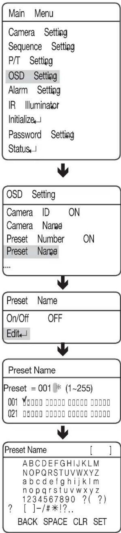
Using this function, you can add names to preset locations up to 12 characters.
Once a name is entered, use the joystick and the Enter key to perform the Set command and save the name.
flowchart
graph TD
    A["Main Menu"] --> B["Camera Setting"]
    B --> C["Sequence Setting"]
    C --> D["P/T Setting"]
    D --> E["OSD Setting"]
    E --> F["Alarm Setting"]
    F --> G["IR Illuminator"]
    G --> H["Initialize"]
    H --> I["Password Setting"]
    I --> J["Status"]
    J --> K["OSD Setting"]
    K --> L["Camera ID ON"]
    L --> M["Camera Name"]
    M --> N["Preset Number ON"]
    N --> O["Preset Name"]
    O --> P["..."]
    P --> Q["Preset Name"]
    Q --> R["On/Off OFF"]
    R --> S["Edit"]
    S --> T["Preset Name"]
    T --> U["Preset = 001 * (1~255)"]
    U --> V["001 ▼□□□□ □□□□□ □□□□□ □□□□□ □□□□□ □□□□□ □□□□□ □□□□□ □□□□□ □□□□□ □□□□□ □□□□□ □□□□□ □□□□□ □□□□□ □□□□□ □□□□□ □□□□ □□□□ □□□□ □□□□ □□□ □□ □□ □□ □□ □□ □□ □□ □□ □□ □□ □□ □ □ □ □ □ □ □ □ □ □ □ □ □ □ □ □ □ □ □ □ □ □ □ □ □ □ □ □ □ □ □ □ □ □ □ □ □ □ □ □ □ □ □ □ □ □ □ □ □ □ ▢"]
    T --> U
    U --> V
    V --> W["Preset Name [ "]
    W --> X["ABCDEFGHIJKLM<br>NOPQRSTUVWXYZ<br>abcdefghijklmnopqrstuvwxyz<br>abcdefghijklmnopqrstuvwxyz<br>1234567890 ?( ?)<br>? [-"]-/#*!?..]
    W --> Y["BACK SPACE CLR SET"]
Home Position
Sets one of the currently configured preset positions as the home position.
Execute
Recalls a saved preset location.
While in the Sequence mode of operation, the actual movement can be slower than specified when moving the camera in the direction of Pan and Tilt at the same time.
Clear
Deletes the selected preset location.
Status
Opens a map of saved preset locations.
An area saved as a preset location is displayed with the 'v' icon.
The Swing function commands the camera to move between 2 selected locations, monitoring the route.
- Pan Swing :
Activates the Pan function for the Swing operation.
- Tilt Swing :
Activates the Tilt function for the Swing operation.
- P/T Swing :
Activates both the Pan and Tilt functions for the Swing operation.
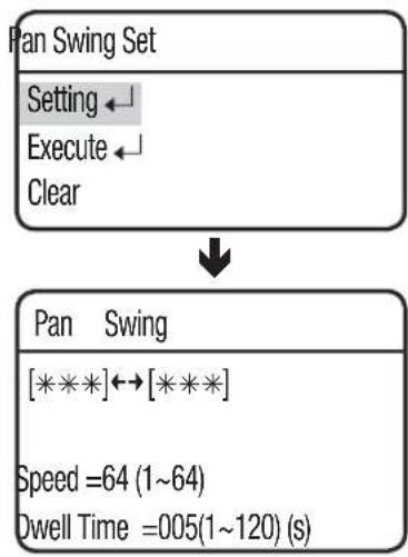
- Swing Setting/Execute/Clear
Each of the Swing menus have sub menus with the settings.
flowchart
graph TD
    A["Pan Swing Set"] --> B["Setting"]
    B --> C["Execute"]
    C --> D["Clear"]
    E["Pan Swing"] --> F["[** * *"] ↔ [*** * *]]
    F --> G["Speed =64 (1~64)"]
    G --> H["Dwell Time =005(1~120) (s)"]
Select 2 preset locations by using the joystick.
Speed indicates the camera's movement speed. DWELL TIME indicates the camera's duration of stay at a preset location.
- Execute: Executes the Swing operation.
- Clear: Deletes data in the Swing memory.

■ While in the Sequence mode of operation, the actual movement can be slower than specified when moving the camera in the direction of Pan and Tilt at the same time.


| Swing SEQ |
| Pan Swing← |
| Tilt Swing← |
| P/T Swing← |
Selecting Group SEQ recalls a group of multiple preset locations in a consecutive manner. Up to 6 groups can be defined and up to 128 presets can be memorized for each group.
During the group operation, the camera settings for each preset will be retrieved accordingly.
- Setting :
Using the joystick, enter the desired preset numbers into the PSET section. DWT indicates the camera's duration of stay at a preset location.
The speed is adjusted in 64 levels.
Executes the group operation.
- Clear :
Deletes the selected group.

■ About 8 seconds of recognition time is required if [Intelligence] of the preset is activated from the Group menu.
For a proper operation of [Intelligence], set [Time (sec)] of the Group menu to more than 8 seconds.
| Main Menu |
| Camera Setting |
| Sequence Setting |
| P/T Setting |
| OSD Setting |
| Alarm Setting |
| IR Illuminator |
| Initialize |
| Password Setting |
| Status |

| Sequence Setting |
| Preset ← |
| Swing SEQ |
| Group SEQ |
| Tour SEQ |
| PTZ Trace |
| Auto Run |
| Power On Resume ON |

| Group | SEQ |
| Group | 1 |
| Group | 2 |
| Group | 3 |
| Group | 4 |
| .... |

| Group SEQ 1 |
| Setting← |
| Execute← |
| Clear← |
Tour SEQ
Selecting Tour SEQ recalls groups of preset locations in a consecutive manner. Up to 6 groups can be listed for this function.
- Setting :
Selecting the Settings menu brings up the following screen. Using the joystick, you can enter desired group numbers to the Group section. DWT indicates the camera's standby time before a new group is recalled.
| Tour SEQ | ||
| NO | Group | DWT(s) |
| 01: * | 003 | |
| 02: * | 003 | |
| 03: * | 003 | |
| 04: * | 003 | |
| 05: * | 003 | |
| 06: * | 003 | |
- Execute :
Executes the group operation.
- Clear :
Deletes the selected group.
| Main Menu |
| Camera Setting |
| Sequence Setting |
| P/T Setting |
| OSD Setting |
| Alarm Setting |
| IR Illuminator |
| Initialize↓ |
| Password Setting |
| Status↓ |
Maximum 4 patterns of the manual operation paths (for Pan, Tilt, Zoom and Focus) are memorized and replayed.
- Replay :
Replays a route saved by the Trace function.
- Replay Once :
Replays a saved Trace route once.
- Memorize :
The time for storing the event differs depending on the complexity of PTZ operations of your choice. When the memory is full, any further storing will be stopped.
You can use the Menu button (OSD access key) to stop the memorize function during its process.
※ Using other protocols
| Protocol | Representative Model | Stop saving the trace |
| PELCO-D/P KDB | 300A Ack, Iris Open | |
| SAMSUNG-E SSC | -5000 | OSD ON, Iris Open |
| PANASONIC WV | CU161C | OSD ON |
| VICON V1300X | -DVC Iris Open | |
| HONEYWELL HTX | -3000 Iris Open | |
| AD | OSD ON, Iris Open | |
| GE KTD-405 | Iris Open | |
| Bosch | Iris Open |
- Clear : Deletes a saved Trace route.
| Main Menu |
| Camera Setting |
| Sequence Setting |
| P/T Setting |
| OSD Setting |
| Alarm Setting |
| IR Illuminator |
| Initialize |
| Password Setting |
| Status |

| Sequence Setting |
| Preset ← |
| Swing SEQ |
| Group SEQ |
| Tour SEQ |
| PTZ Trace |
| Auto Run |
| Power On Resume ON |

| PTZ | Trace |
| Trace | 1 |
| Trace | 2 |
| Trace | 3 |
| Trace | 4 |

| PTZ Trace |
| ReplayReplay OnceMemorizeClear |
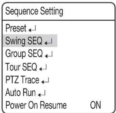
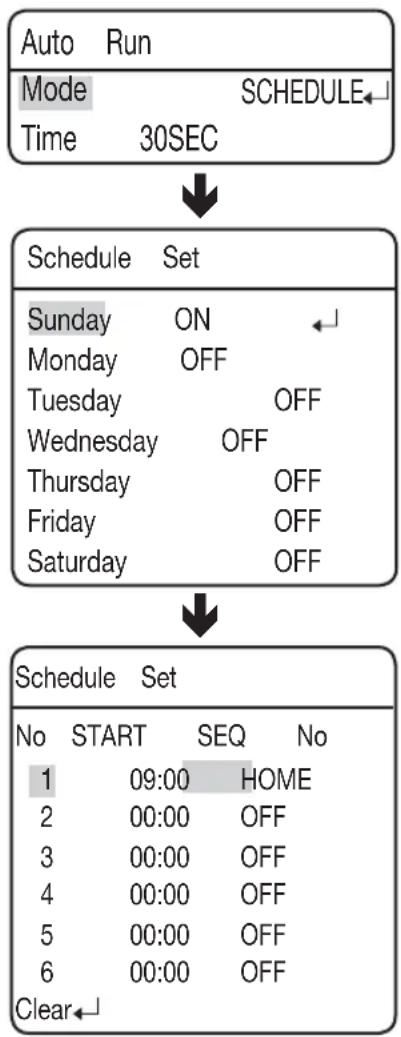
Auto Run
If an operator is not controlling the dome at a specific time, the sequence operation scheduled by the user will be executed.
- Mode :
- HOME : Auto run Home Position (Refer to the Preset Menu.)
- PRESET : Auto run a selected preset number.
- SWING : Auto run a selected Swing mode.
- GROUP : Auto run a selected Group mode.
- TOUR : Auto run a selected Tour mode.
-TRACE: Auto run a selected trace mode. - A.PAN: Auto run a 360-degree pan. To activate the panning command, you need to set up the camera's tilt angle and auto pan speed manually.
- SCHEDULE : Execute Auto Run on the selected day of the week.
- Time :
Enables setting up an Auto Run duration. (The duration can be 5\~30 seconds, or 1\~5 minutes.)
| Main Menu |
| Camera SettingSequence SettingP/T SettingOSD SettingAlarm SettingIR IlluminatorInitializePassword SettingStatus |

| Sequence Setting |
| Preset ← |
| Swing SEQ |
| Group SEQ |
| Tour SEQ |
| PTZ Trace |
| Auto Run |
| Power On Resume ON |

| Auto | Run | |
| Mode | OFF | |
| Time | 30 | SEC |
◆ Schedule
Schedule enables you to set a sequencing action by day and time.
- Select Day :
At Auto Run, select SCHEDULE to set up each day of the week, as shown on the side picture. Select a day, change to ON, and then press Enter.
- Select Time :
When turning ON a day, a timetable appears as shown on the side picture. (Up to 6 timelines can be selected for a day.) Select the beginning time and sequencing action to schedule the action.
flowchart
graph TD
    A["Auto Run"] --> B["Mode SCHEDULE"]
    B --> C["Time 30SEC"]
    C --> D["Schedule Set"]
    D --> E["Sunday ON"]
    E --> F["Monday OFF"]
    F --> G["Tuesday OFF"]
    G --> H["Wednesday OFF"]
    H --> I["Thursday OFF"]
    I --> J["Friday OFF"]
    J --> K["Saturday OFF"]
    K --> L["Schedule Set"]
    L --> M["No START SEQ No"]
    M --> N["1 09:00 HOME"]
    M --> O["2 00:00 OFF"]
    M --> P["3 00:00 OFF"]
    M --> Q["4 00:00 OFF"]
    M --> R["5 00:00 OFF"]
    M --> S["6 00:00 OFF"]
    M --> T["Clear"]
Power On Resume
● Power On Resume :
This is useful when the power is disconnected and reconnected due to power failures or other power interruptions.
If the camera was performing a sequence action prior to a power disconnection, the camera automatically resumes the action when the power is reconnected.
flowchart
graph TD
    A["Main Menu"] --> B["Camera Setting"]
    B --> C["Sequence Setting"]
    C --> D["P/T Setting"]
    E["Sequence Setting"] --> F["Preset"]
    F --> G["Swing SEQ"]
    F --> H["Group SEQ"]
    F --> I["Tour SEQ"]
    F --> J["PTZ Trace"]
    F --> K["Auto Run"]
    F --> L["Power On Resume ON"]
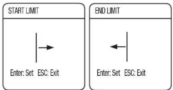
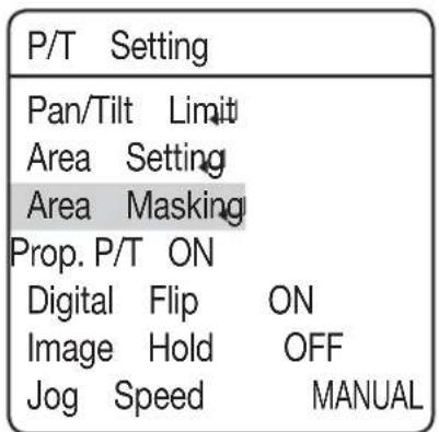
P/T Setting
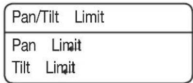
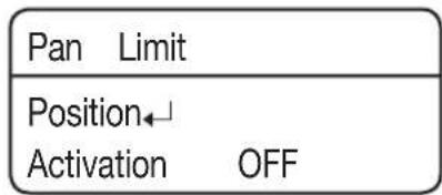
Pan/Tilt Limit
The moving ranges in the Pan/Tilt directions can be limited.
- Position :
Selecting the Position menu brings up the following screen if it is for the Pan Limit setting. Move the joystick left and right to select a movement range from the starting point to the end.
flowchart
graph TD
    A["Start"] --> B["→"]
    C["Start"] --> D["Enter: Set ESC: Exit"]
    E["End"] --> F["←"]
    G["End"] --> H["Enter: Set ESC: Exit"]
The following picture shows the Tilt Limit setting.
Move the joystick left and right to select a movement range from the starting point to the end.
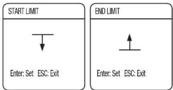
- Activation :
Sets the configured Pan/Tilt Limit function to use or not.


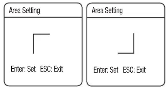
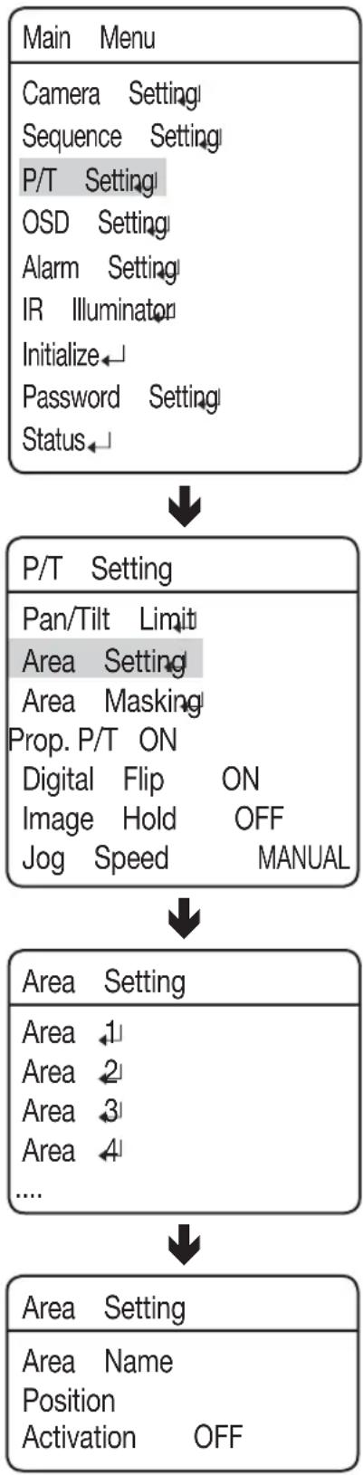
Area Setting
The Area Setting menu enables the selection of certain locations in the course of the Pan and Tilt operation, and then display the areas with the OSD (On Screen Display) texts when the camera passes through them. Up to 8 areas can be selected.
- Area Name :
You can add names to selected areas. Names can be up to 12 characters and can be entered via the joystick and the Enter key. Once a name is entered, use the joystick and the Enter key to perform the Set command and save the name.
| Area Name [ ] |
| ABCDEFGHIJKLMNOPQRSTUVWXYZ abcdefghijklmnopqrstuvwxyz 1234567890 ?( ?) ? [ ]-/#*!?,. |
| BACK SPACE CLR SET |
- Position :
As shown in the picture below, move the joystick to select the upper left corner and lower right corner of an area.
flowchart
graph TD
    A["Area Setting"] --> B["Enter: Set ESC: Exit"]
    C["Area Setting"] --> D["Enter: Set ESC: Exit"]
The effective positioning range is between -45^ and 40^ in the tilting angle at the zoom factor of 1x.
- Activation :
Cancels or activates the display function of selected areas.
flowchart
graph TD
    A["Main Menu"] --> B["P/T Setting"]
    B --> C["Area Setting"]
    C --> D["Area Setting"]
    D --> E["Area Name Position Activation OFF"]
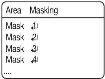
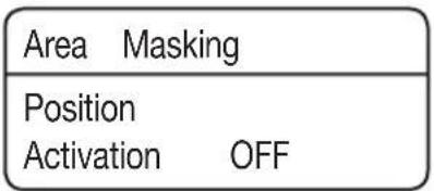
Area Masking
If a monitoring location includes a highly private area, the area can be selectively excluded from monitoring.
- Position :
- As shown in the picture below, move the joystick to select the upper left corner and lower right corner of an area.
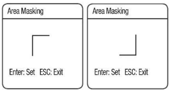
- Activation :
Activate or deactivate the display of specified masks.


This commands the camera to change the Pan and Tilt speed automatically according to the current zoom ratio. Moving the joystick clockwise (Tele) slows down and counterclockwise (Wide) accelerates the Pan and Tilt speed, allowing detailed adjustments. Turning this "Off" executes the function the optical 1x zoom speed regardless of how far the lens is zoomed in.
| Main Menu |
| Camera SettingSequence SettingP/T SettingOSD SettingAlarm SettingIR IlluminatorInitializePassword SettingStatus |

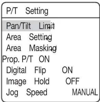
| P/T Setting | |
| Pan/Tilt Limit | |
| Area Setting | |
| Area Masking | |
| Prop. P/T ON | |
| Digital Flip ON | |
| Image Hold OFF | |
| Jog Speed MANUAL |
Digital Flip
Digital Flip is useful to monitor a moving object or a person passing directly under the camera.
When the object passes straight under the camera, tilting can be traced up to the opposite tilting area without the need of the pan operation. The reverse screen that occurs when the object gets through the 90-degree point will be corrected in digital processing.
- 0^ 180^ : Image flip at the 93-degree point
- 180^ 0^ : Image flip at the 87-degree point
| Main Menu |
| Camera SettingSequence SettingP/T SettingOSD SettingAlarm SettingIR IlluminatorInitializePassword SettingStatus |

| P/T Setting | ||
| Pan/Tilt Limit | ||
| Area Setting | ||
| Area Masking | ||
| Prop. P/T ON | ||
| Digital | Flip | ON |
| Image | Hold | OFF |
| Jog | Speed | MANUAL |
Image Holding
This will display the preset video in still images until the orientation of the camera reaches the preset position at a group or tour movement.
This is useful if you want to monitor the video while preventing a possible visual distraction of the observer.
| Main Menu |
| Camera SettingSequence SettingP/T SettingOSD SettingAlarm SettingIR IlluminatorInitializePassword SettingStatus |

| P/T Setting | ||
| Pan/Tilt Limit | ||
| Area Setting | ||
| Area Masking | ||
| Prop. P/T ON | ||
| Digital Flip ON | ||
| Image Hold OFF | ||
| Jog Speed MANUAL |
Jog Speed
The pan/tilt speed changes according to the tilt of the joystick, or you can control the operation in a fixed speed.
- MANUAL :
The pan/tilt speed depends on how much the joystick of the controller is tilted. The more the joystick is tilted, the faster the operation is performed.
● 30/35/40/45/50/55/60 :
The pan/tilt operation will be performed at the selected speed; the greater the number is, the faster the operation is performed. However, the speed at each level may differ according to the zooming status, and depending on the use of synchronized zooming.
| Main Menu |
| Camera Setting |
| Sequence Setting |
| P/T Setting |
| OSD Setting |
| Alarm Setting |
| IR Illuminator |
| Initialize |
| Password Setting |
| Status |

| P/T Setting | |
| Pan/Tilt Limit | |
| Area Setting | |
| Area Masking | |
| Prop. P/T ON | |
| Digital Flip ON | |
| Image Hold OFF | |
| Jog Speed MANUAL |
In this menu, you can configure the OSD (On Screen Display) settings.
- Camera ID :
Displays or hides Camera ID in the upper left of the screen.
- Camera Name :
Add a name to the camera. (see the top note on page 66 for more information.)
- Preset Number :
Displays or hides Preset Numbers on the screen.
- Preset Name :
Add names to preset locations. (see the top note on page 66 for more information.)
- Seq. Status :
Displays or hides the status of a sequence action that is in progress.
- Area Name :
Displays or hides the Area Name for the Area Settings on the screen.
- PTZ Position :
Displays or hides the status of the Pan, Tilt, and Zoom operation that is in progress.
- Language :
Enables the system language to be changed. This camera supports ENGLISH, CHINESE, FRENCH, GERMAN, SPANISH, ITALIAN, PORTUGUES, POLISH, RUSIAN, CZECH, TURKISH, KOREAN, JAPANESE, TAIWANESE.
- Others
Main Menu
Camera Setting
Sequence Setting
P/T Setting
OSD Setting
Alarm Setting
IR Illuminator
Initialize
Password Setting
Status

OSD Setting
Camera ID ON
Camera Name
Preset Number ON
Preset Name
Seq. Status ON
Area Name OFF
PTZ Position ON
Language ENGLISH
Others
OSD Setting
Direction
Clock Setting
- Direction : Indicates the current angle of the camera:
East, West, South, North, Southeast, Southwest, Northeast, or Northwest.
■ Set North Dir. : Specify the azimuth of the north manually.
- Clock Setting: You can specify the time information manually that will be displayed on the screen. This will synchronize with Sequence so that you can set it to activate on a specific time and date.
■ Display: Specify the use of time display on the screen.
■ Date Format: Specify the date format. (DD/MM/YYYY, MM/DD/YYYY)
■ Set Date: Enter a desired date manually.
■ Time Format: Specify the time format. (24hr / 12hr)
■ Set Time: Specify the time manually.
| XXX Name [ ] |
| ABCDEFGHIJKLMNOPQRSTUVWXYZ abcdefghijklm nopqrstuvwxyz 1234567890 ( ) [ ]-/#*!?.. |
| BACK SPACE CLR SET |

■ When selecting the Camera Name and Preset Name, the screen displays the Left keypad.
■ Names can be up to 12 characters and can be entered via the joystick and the Enter key. Once a name is entered, use the joystick and the Enter key to perform the Set command and save the name.
ALARM SETTING
Alarm Enable
- ON/OFF :
Enables or disables the Alarm function.
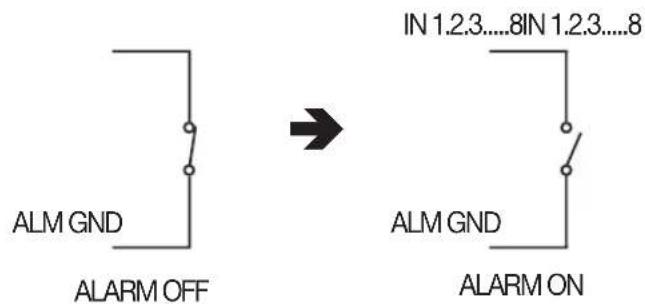
Alarm Input
• MOD
Enables selecting an Alarm Input method.
- NO (Normally Open)
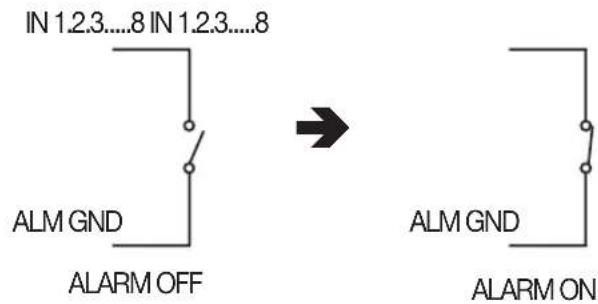
- NC (Normally Closed)
| Main Menu |
| Camera Setting |
| Sequence Setting |
| P/T Setting |
| OSD Setting |
| Alarm Setting |
| IR Illuminator |
| Initialize← |
| Password Setting |
| Status← |

| Alarm Setting | |
| Alarm Enable OFF | |
| Alarm Input | |
| Alarm/AUX Output | |
| MD Dwell Time OFF | |
| ALM Dwell Time HOLD |

| ALM | MOD | P | SEQ. | NO |
| N1 | OFF | 1 | OFF | |
| N2 | OFF | 2 | OFF | |
| N3 | OFF | 3 | OFF | |
| ...... | ||||

As shown in the picture above, the Alarm Input must be entered with the Open or Closed switch signals. Supplying power without entering the signals may damage the product.
- P(Priority) :
Set the priority of Alarm Inputs. If more than one alarm is simultaneously activated, the alarm with the highest priority activates before the others.
- SEQ.:
Enables setting up a sequence action for the camera in response to an alarm.
You can configure the settings of: HOME/PRESET/SWING/GROUP/TOUR/TRACE/A.PAN/OFF
Alarm/AUX Output
- Setting 1, 2, 3 :
Enables selecting an Alarm Output method.
- DETECT MODE : Displays the alarm input ports (1\~8) and the motion detection input. If you set MD Input, you can select one from: OFF/MD.
- AUX MODE : Both Alarm OUT/AUX OUT 1 and 2 are NC/NO while Alarm OUT/AUX OUT 3 performs NO only.
- Timer 1, 2, 3 :
-On: If an alarm event occurs, the alarm will stay active for the time specified. You can specify the time from at least one second to a max of 60 minutes.
- MOMENT : The output operation will last until an alarm/AUX event is released since its occurrence.
- The Alarm/AUX output system is equipped with a relay circuit, whose output port operates as below: (based on "NO")
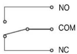
Alarm Out OFF

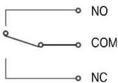
Alarm Out ON
- OUT Off 1, 2, 3 :
- Output of an alarm/AUX event can be forcibly terminated when it occurred.
| Main Menu |
| Camera Setting |
| Sequence Setting |
| P/T Setting |
| OSD Setting |
| Alarm Setting |
| IR Illuminator |
| Initialize |
| Password Setting |
| Status |

| Alarm Setting | |
| Alarm Enable OFF | |
| Alarm Input | |
| Alarm/AUX Output | |
| MD Dwell Time OFF | |
| ALM Dwell Time HOLD |

| Alarm/AUX | Output | |
| Setting | 1 | DETECT MODE← |
| Setting | 2 | DETECT MODE← |
| Setting | 3 | DETECT MODE← |
| Timer | 1 | OFF |
| Timer | 2 | OFF |
| Timer | 3 | OFF |
| Out Off | 1 | |
| Out Off | 2 | |
| Out Off | 3 | |

■ Connecting the power connector and GND incorrectly to the NC/NO and COM ports may cause a short circuit and fire, damaging the camera.
The maximum power capacity of the built-in relay is 30VDC/2A, 125VAC/0.5A, and 250VAC/0.25A. Operating the camera beyond the capacity may decrease the camera's lifespan and damage it.
MD Dwell Time
When Motion Detection under the Preset Edit menu is selected, MD Dwell Time performs the Tour or Group function.
While the camera is performing a sequence action, if motion is detected from a selected preset location, the camera pauses the sequence action operation and starts monitoring the location instead for a duration that is set under the MD Dwell Time menu. If the motion is no longer detectable or the duration expires, the camera aborts the monitoring operation and then resumes the sequence action.
| Main Menu |
| Camera Setting |
| Sequence Setting |
| P/T Setting |
| OSD Setting |
| Alarm Setting |
| IR Illuminator |
| Initialize |
| Password Setting |
| Status |

| Alarm Setting | |
| Alarm Enable OFF | |
| Alarm Input | |
| Alarm/AUX Output | |
| MD Dwell Time OFF | |
| ALM Dwell Time HOLD |
ALM Dwell Time
You can specify the time of sequence operation that will be activated if an event occurs from the alarm input.
- SET:
The sequence operation will proceed for a specified time.
- HOLD:
The sequence operation will be maintained until the user deactivates it.

The alarm dwell time will be activated while the "Sequence Setting > Auto Run" option is active.
In this menu, you can configure the IR Illuminator settings against a low contrast scene.
- IR Mode: Specify the use conditions for the IR Illuminator.
- Off: Does not use the IR Illuminator.
- On: Activates the IR Illuminator.
- DAY/NIGHT: Synchronizes the IR Illuminator with Day/Night mode of the camera. Set the Day/Night mode so that the product uses the IR Illuminator in the night but does not use the illuminator during the day.
- SENSOR: It will be in sync with the built-in brightness sensor of the camera. See the next page for details.
-TIMED: Set the IR Illuminator to activate/deactivate at a specified time. See the next page for details.

If the IR mode is set to ON and the LED turns on, the screen will be displayed in black and white mode. If the LED turns off, the screen will return to the previous screen mode.
If you set the IR mode to "DAY/NIGHT", "Camera Setting>Day/Night>Mode" will be set to "Auto", which you cannot change the setting.
If you set the IR mode to Sensor or Time mode, you cannot change "Camera Setting> Day & Night > Mode" as you want.
- When used with IR illuminator, changing the zoom ratio automatically synchronizes the IR illuminator. Note that synchronizing IR illuminator to zooming may slow down in low temperatures.
If the ambient temperature increases too high, the IR LED can turn off to prevent overheat of the product.
| Main Menu |
| Camera Setting |
| Sequence Setting |
| P/T Setting |
| OSD Setting |
| Alarm Setting |
| IR Illuminator |
| Initialize |
| Password Setting |
| Status |

| IR | Illuminator | |
| IR | Mode | DAY/NIGHT← |
| LED | Max.Power | MEDIUM |
| LED | Pwr.Ctrl | AUTO |
| Focus | Limit | ON |
- LED Max. Power: Specify the maximum output of the IR Illuminator.
- LOW/MEDIUM/HIGH: The higher the level is, the brighter the indicator of the IR Illuminator becomes.
- LED Pwr.Ctrl: Set to control the indicator's output of the IR Illuminator.
- AUTO : If the light from the IR indicator reflects on a short-distant object (causing saturation), this will lower the max power of the IR indicator.
- MANUAL :Limit the output of the indicator to the value specified in "LED Max. Power".
- Focus Limit: This is to restrict the auto focusing in a high zoom factor of the IR illuminator in order to prevent unnecessarily extended duration of the auto focusing.
- On: If the IR indicator turns on and the zoom factor is at least x21, the focus mode will be set to Manual regardless of the focus mode settings.
In Sequence mode, the focus will return to the preset value regardless of the focus mode settings. To guarantee exact operation at night, you must make the preset settings in advance.
If you use the joystick to control the Pan/Tilt/Zoom operations, the focus mode will switch to "Manual". However, if you still want to enable the auto focusing, press the A/F button on the controller to activate the auto focus mode.
For optimal IR performance, the intensity of the IR LED will be set to High regardless of the user settings.
- Off: The user focus settings and LED output settings will be applied.
SENSOR:
In this mode, the IR mode will be controlled according to the illumination.
The “level” on the top right corner indicates the current illumination.
- LED On Level : Specify the illumination level that activates the IR mode. If the illumination is below the specified level, the indicator will turn on.
- LED Off Level : Specify the illumination level that deactivates the IR mode. If the illumination is above the specified level, the indicator will turn off.
| IR | Illuminator | |
| IR | Mode | SENSOR |
| LED | Max.Power | MEDIUM |
| LED | Pwr.Ctrl | AUTO |
| Focus | Limit | ON |

| Sensor Mode | Level =100 |
| LED On Level | 040 |
| LED Off Level | 060 |

■ LED ON Level cannot be higher than LED Off Level; LED Off Level cannot be lower than LED On Level.
■ The sensor mode will be triggered if the lighting stays at a certain illumination for more than 5 seconds.
Level difference between "LED ON Level" and "LED OFF Level" cannot be less than or equal to 10.
If the Sensor mode is set to ON and the LED turns on, the screen will be displayed in black and white mode. If the LED turns off, the screen will be displayed in color mode.
TIMED:
You can use this option to set the IR Illuminator to On/Off at your specified time.
- LED On Time: Specify the time to activate the IR mode.
- LED Off Time: Specify the time to deactivate the IR mode.
| IR | Illuminator | |
| IR | Mode | TIMED← |
| LED | Max.Power | MEDIUM |
| LED | Pwr.Ctrl | AUTO |
| Focus | Limit | ON |

| TIMED Mode | |
| Led On Time | 19:00 |
| Led Off Time | 05:00 |

If the Time mode is set to ON and the LED turns on, the screen will be displayed in black and white mode. If the LED turns off, the screen will be displayed in color mode.
● Power On Reset :
Restarts the camera.
● Factory Default Set :
Enables resetting the camera to its factory default settings. When the mode is selected, all custom data such as preset locations are deleted from the camera.
Use this function if it is necessary to reset the settings of the camera.
- Camera Default Set :
Reset the zoom module of the camera to the factory default. Use this if you want to return the camera settings of such as Exposure or Backlight to the factory default.
- Auto Refresh :
Optimizes the settings of the electric circuits and component parts of the camera on a regular basis.
This is useful for maintenance purpose, especially when the camera faces a specific light source, or if the camera settings are not maintained properly due to an extended time of recording while rotating the camera in four directions.
- Off, 1\~7 Days : Selecting Off disables Auto Refresh and selecting 1\~7 Days automatically executes it after 1\~7 days has passed.
※ Auto Refresh takes about 10 seconds or less. Any sequence operation that is being performed will be stopped and resume after Auto refresh is completed.
| Main Menu |
| Camera Setting |
| Sequence Setting |
| P/T Setting |
| OSD Setting |
| Alarm Setting |
| IR Illuminator |
| Initialize↓ |
| Password Setting |
| Status↓ |

| Initialize | ||
| Power On Reset ← Factory Default Set ← Camera Default Set ← Auto Refresh OFF Fan Life |
● Fan Life :Enables setting the Fan Life.
- Message Display: The following warning message will appear 2 months before the expiry of the fan life. "Fan Life Expired. Replace the Fans"
▶ ON: Display the warning message. (Default)
▶ OFF: Do not display the warning message.
※ [OFF] is to hide the message, rather than to delete it. Set it back to [ON]. Then, the warning message will appear. (Only if you didn't clear the message [Message Clear])
- Message Clear: Use this if you want to delete the warning message when it pops up.
※ If you set [Message clear] to [On] after performing the command, no warning message will appear on the screen.
- Time Reset: Set to count the fan life again after replacing the fan. (However, this is available only after you see a warning message that the fan life has expired.)
※ The fan life is counted only for an actual operation so the fan can be used longer than the displayed time.
- Time Remain.(hour):
▶ 49000 : Remaining life of fan (unit: hour)
The fan life will be updated when you access the [Fan Life] menu and if you press [ENTER] on the [Time Remain.(hour)] item.
PASSWORD SETTING
The Password feature enables you to configure a password for rebooting the camera and accessing the OSD and preventing unauthorized modification of existing camera settings.
- On/Off :
Enables or disables Password protection.
- Edit Password
Change the password; enter the current password and then a new one, consisting of 4 hexadecimal characters (0\~F).
* The default password is "0000".
| Main Menu |
| Camera Setting |
| Sequence Setting |
| P/T Setting |
| OSD Setting |
| Alarm Setting |
| IR Illuminator |
| Initialize← |
| Password Setting |
| Status← |

| Password Setting |
| On/Off OFFEdit Password |
STATUS
Displays the settings and version of the camera.
- CAM MODEL :
Indicates the model name of the camera.
- CAM VER.:
Indicates the software version of the camera.
• DOME VER. :
Indicates the version of the camera control board.
- COAX VER.:
Indicates the software version of the Coax communication
- PROTOCOL :
Indicates the status of the current protocol.
• DOME ID :
Dome Camera ID
- CONTROLLER :
Indicates the settings of the current communications mode.
- MODEL NAME :
Shows the model name of the product.
| Main Menu |
| Camera Setting |
| Sequence Setting |
| P/T Setting |
| OSD Setting |
| Alarm Setting |
| IR Illuminator |
| Initialize← |
| Password Setting |
| Status← |

| Camera Status |
| CAM MODEL = SCM2370/PAL |
| CAM VER. = V2. 06_111101 |
| DOME VER. = V0. 50_111220 |
| COAX VER. = V1. 00_110126 |
| PROTOCOL = AUTO DET |
| DOME ID = 001 |
| CONTROLLER = Simplex |
| MODEL NAME = SCP-2370RH |
TROUBLESHOOTING
If the product does not function properly, please see the below for trouble shooting.
| Problem Cause and Solution Page | ||
| Controller does not work. | ▶ Check if the camera and peripheral devices are properly connected. 12~14 | |
| ▶ Verify the setups of ID, protocol, and baud rates. 15~26 | ||
| No picture is displayed on monitor. | ▶ Check if power cable is securely connected to the camera and the monitor. Check if the video cable is properly connected. Consult the operation manual of the system controller connected to the camera. | 12~14 |
| ▶ Check if the iris of the lens is closed. Adjust the menu for the iris of the lens. | 40 | |
| ▶ Check the camera's fixed shutter speed. Adjust the camera's shutter menu. | 40 | |
| The picture is too dark/bright. | ▶ Check the camera's Brightness menu. Adjust the camera's Brightness menu. | 40 |
| The monitor displays a white image. | ▶ Check if the iris of the lens is open. Adjust the menu for the iris of the lens. | 40 |
| Picture is out of focus. | ▶ Verify the distance between the camera and the subject, as well as the subject's surroundings. Camera may have difficulty focusing on a subject against a white background. | - |
| ▶ If Auto Focusing is having difficulty focusing on a particular subject, set Focus Mode to Manual and adjust the focus by yourself. | 38 | |
| ▶ Use the camera's reset menu to restore the camera settings in order to default. | 71 | |
| ▶ Adjust Sharpness level. 47 | ||
| ▶ This can happen if the IR LED turns on with the zoom factor set to at least x21. | 69 | |
| Digital noise appears in picture. | ▶ Check if the video cable is properly connected. - | |
| ▶ Make sure that the power cable and video cable do not exceed the recommended maximum lengths. | 27 | |
| ▶ Adjust Sharpness level. 47 | ||
| Picture's colors are not good. | ▶ Check the White Balance. 39 | |
| ▶ Adjust Color Menu in Image Adj. 47 | ||
| The picture is flickering. | ▶ Check if the camera is pointing directly at a fluorescent light or sunlight. If so, change the camera's direction to remove the flickering. | - |
| Afterimages appear in picture. ▶ | Check Sens-Up settings. 40 | |
| Camera switches between color and B&W modes frequently. | ▶ Adjust Duration and Dwell Time in Day & Night menu. 46 | |
| Pan, tilt, zoom, and/or focus do not work. | ▶ Check if power cable is securely connected to the camera and the monitor. Check if the video cable is properly connected.Consult the operation manual of the system controller connected to the camera. | 12~14 |
| ▶ Check if Pan Limit and/or Tilt Limit are set.If so, remove the limit(s). | 58 | |
| ▶ A motor or the lens may be overheated.If so, contact your service personnel or system provider for assistance. | - | |
| The camera's position differs from the position defined in a preset. | ▶ This phenomenon may happen, since the motors have a margin error of ±0.1°. | - |
| Sequence configuration of the camera does not work. | ▶ Check if Preset or another operation mode has been set.▶ Check the Auto Refresh settings. | 48~49 |
| The upper side of the picture is dark when the camera is on the horizontal reference point. | ▶ You are seeing the camera's internal cover. The camera is functioning normally. | - |
| Camera suddenly turns on or moves to a preset position by itself. | ▶ Check the Auto Run settings.Auto Run puts a camera through a predefined action sequence if the user does not use the Controller to operate the camera for a certain period of time. | 56 |
| ▶ Check the Auto Refresh settings.Auto Refresh optimizes the camera's circuitry and components according to a predefined schedule. | 71 | |
| Coxial communication does not work. | ▶ Check the distance between the camera and the monitor. 27 | |
| ▶ If the distance between the camera and the monitor exceeds the recommended maximum, please use an auxiliary video amp. | 27 | |
| ▶ Ensure that the Camera ID DIP switches (SW1) are all positioned to OFF. 19 | ||
| I turned on the power, but the camera didn't start running. | ▶ Please check the environment temperature; the camera may not operate properly if it has been left at temperatures lower than -50° for a prolonged duration. | 6~7 |
| ▶ The motor may malfunction at temperatures lower than -20°; please turn on the camera in Standby mode instead of [Initialize]. | 6~7 | |
| ▶ Keep in Standby mode for at least 120 minutes. Once the internal temperature reaches -20° or higher, the camera automatically resets itself and activates the [Initialize] mode for normal operation. | 6~7 | |
| I can't see the screen.(The screen is black.) | ► When the camera's internal temperature drops down to -20° or lower, it becomes unable to transmit video signals and may cause a black screen. | 6~7 |
| ► A black screen does not indicate camera breakage; it resets itself and starts displaying video again once its internal temperature reaches -20° or higher. | 6~7 | |
| The camera stops in the Initialize mode and won't proceed to the next mode. | ► The motor may malfunction at temperatures lower than -20°; please turn on the camera in Standby mode instead of [Initialize]. | 6~7 |
| I can use the controller, but I can't activate the Sequence command. | ► When the camera's internal temperature is between -10° to -20°, the motor may malfunction, limiting the use of the Sequence and Turbo commands. | 6~7 |
| ► Once the internal temperature reaches -10° or higher, all Sequence modes become reactivated normally. | 6~7 | |
| I can't get rid of this message from the screen: “Fan life Expired. Replace the Fans.” | ► Please make sure to "Clear" the message from the screen. 6~7 | |
| The camera suddenly resets itself while displaying the black screen. | ► Such symptoms may occur if the camera's temperature increases from -20° or lower to -20° or higher. | 6~7 |
| "Auto Refresh(Wait)" appears and the camera reboots. | ► Such symptoms may occur if the camera's temperature increases from -10° or lower to -10° or higher to prevent the malfunction of motor. | 6~7 |
| "Please Check Heater System" appears. | ► The heater may malfunction.Turn off the camera and call where you bought. | 6~7 |
| Check the Power cord's by periods | ||
| ·The Power cord's coating has been damaged.·The power cord is hot to touch when the product is in operation.·The power cord gets hot after being folded or pulled on. | Continuing to use the product when its power cord is damaged constitutes an electrical and fire hazard. The power plug must be removed from the outlet immediately, and a qualified service personnel or your system provider should be contacted for assistance. | - |
PRODUCT SPECIFICATIONS)
| Model SCP-2370RH | |
| Image Device 1/4" Super HAD CCD | II |
| Total Pixels | NTSC : 811(H) x 508(V) |
| PAL : 795(H) x 596(V) | |
| Effective Pixels | NTSC : 768(H) x 494(V) |
| PAL : 752(H) x 582(V) | |
| Scanning System 2:1 Interlace | |
| Synchronization Internal / Line Lock | |
| Frequency | NTSC : H : 15.734kHz / V : 59.94Hz |
| PAL : H : 15.625KHz / V : 50Hz | |
| Horizontal Resolution | Color : 600TV lines / BW : 700TV lines |
| Min. Illumination | |
| 0 Lux | |
| COLOR : 0.2 Lux (50 IRE @ F1.6), 0.0004 Lux (50IRE, Color, Sens-up 512x)B/W : 0.02 Lux (50 IRE @ F1.6), 0.00004 Lux (50IRE, B/W, Sens-up 512x) | |
| S / N Ratio 52 dB (AGO off, Weight On) | |
| Video Output CVBS : 1.0 Vp-p / 75Ω composite | |
| Focal Length(Zoom Ratio) | 3.5~129.5mm |
| Max. Aperture Ratio 1:1.6 (Wide) ~ 3.9 (Tele) | |
| Angular Field of View H : 55.5°(Wide) ~ 1.59°(Tele) / V : 42.5°(Wide) ~ 1.19°(Tele) | |
| Min. Object Distance 1500mm | |
| Focus Control AUTO / MANUAL / ONE SHOT | |
| Zoom Movement Speed | 2.8sec |
| Pan Range 360° Endless | |
| Pan Speed Preset : 250°/sec, Manual : 0.024°/sec ~ 120°/sec | |
| Tilt Range -5° ~ 185° | |
| Tilt Speed Preset : 250°/sec, Manual : 0.024°/sec ~ 120°/sec | |
| Preset 255 | |
| Preset Accuracy | ±0.1° |
| OSD | NTSC: ENGLISH, FRENCH, SPANISH, PORTUGUES, KOREAN, JAPANESE, TAIWANESEPAL: ENGLISH, CHINESE, FRENCH, GERMAN, SPANISH, ITALIAN, PORTUGUES, POLISH, RUSIAN, CZECH, TURKISH |
| Camera Title | Off / On (Displayed 12 Characters) |
| Day & Night Auto (ICR) / Color / B/W | |
| Back Light BLC / HLC / Off | |
| Contrast Enhancement | SSDR (Off/On) |
| Digital Noise Reduction | SSNR III (Off/On) |
| Digital Image Stabilization | Off/On |
| Motion Detection Off/On | |
| Privacy Masking Off/On (8 programmable zones) | |
| Sens-up 2x ~ 512x | |
| Gain Control Off/Low/Medium/High/Manual | |
| White Balance ATW / ATW (IN) / ATW (OUT) / Manual / AWC | |
| Electronic Shutter Speed | NTSC :1/60~1/120,000sec |
| PAL : 1/50~1/120,000sec | |
| Digital Zoom Off/On (2x ~ 16x) | |
| Digital Flip Off/On | |
| Schedule Day/Time | |
| Alarm 8 In 3 Out | |
| Communication RS-485/422, Coaxial Control | |
| Protocol | Coax : Pelco-C (Coaxitron)RS-485: Auto Detected, SAMSUNG-T, SAMSUNG-E, Pelco(D/P), Panasonic, Vicon,Honeywell,AD,GE,BOSCH |
| Operating Temperature / Humidity | -50°C ~ +55°C / Less than 100% RH |
| Ingress Protection IP66 | |
| Input Voltage | 24V AC ±10%, 50/60Hz |
| Power Consumption 15W / Max. 90W (Fan & Heater) | |
| Color / Material Ivory, Aluminum | |
| Dimension (Φ×H) Φ248 x 399.5mm | |
| Weight | 6 Kg |
※ The specification for this product may change without prior notice for product improvement.
DIMENSIONS
Unit : mm (inch)
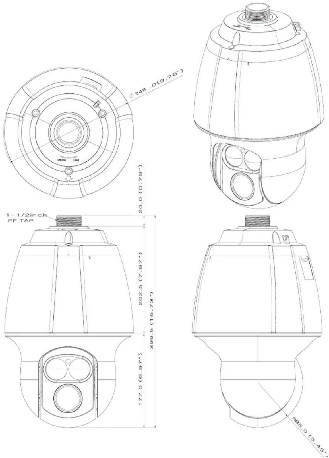
78_ product specifications
MEMO
SAMSUNG
SALES NETWORK
SAMSUNG TECHWIN CO., LTD.
Samsungtechwin R&D Center, 701, Sampyeong-dong, Bundang-gu, Seongnam-si, Gyeonggi-do, Korea, 463-400
TEL : +82-70-7147-8740\~60, FAX : +82-31-8018-3745
100 Challenger Rd. Suite 700 Ridgefield Park, NJ 07660
Toll Free : +1-877-213-1222 Direct : +1-201-325-6920
Fax: +1-201-373-0124
www.samsungcctvusa.com
SAMSUNG TECHWIN EUROPE LTD.
Samsung House, 1000 Hillswood Drive, Hillswood Business Park
Chertsey, Surrey, UNITED KINGDOM KT16 OPS
- Trademark
- Restriction
- Disclaimer
- Warranty
- CAUTION
- WARNING
- FCC Statement
- IC Compliance Notice
- Correct Disposal of This Product (Waste Electrical & Electronic Equipment)
- Correct disposal of batteries in this product
- 4\_ safety information
- important safety instructions
- DETAILED WARNINGS AND CAUTIONS
- CAUTIONS FOR OPERATING TEMPERATURE
- 6\_ important safety instructions
- INTRODUCTION
- CONNECTION & INSTALLATION
- SETUP
- TROUBLESHOOTING
- PRODUCT SPECIFICATIONS
- FEATURES
- • A/F 37x Optical Zoom
- - Versatile protocols and coaxial communication
- - Wide Range Auto Security Functions
- - Digital Flip
- - Smart P/T
- - Day & Night
- • Highly durable built-in housing
- WHAT'S INCLUDED
- Front Back
- Bottom
- CAMERA WIRING INTERFACE BOARD
- HOW TO SET UP PROTOCOLS AND ID DIP SWITCHES
- COMMUNICATION PROTOCOL DIP SWITCH SETTINGS (SW2)
- Protocol Settings
- Baud Rate Settings
- Communication Method Settings
- Communication Response Settings
- Termination Settings
- Camera Backup Settings
- CAMERA ID DIP SWITCH SETTINGS (SW1)
- PREPARING ADAPTER AND CABLES
- - Power Adapter
- - Video Cable
- • Communications Cable
- PREPARING & INSTALLING CAMERA BRACKET
- OPTIONAL ACCESSORIES FOR INSTALLATION
- ◆ Fixing the installation base to the bracket
- INTERFACE SYMBOLS
- USING AND SETTING THE MENUS
- OSD (On-screen Display) Indicators
- Operating Your Camera
- OSD Commands, Function Chart, and Menu Controls (Applied to Samsung T/Samsung E protocol)
- OSD Menu Chart
- CAMERA SETUP
- Zoom and Focus Settings
- - Focus Mode
- - Zoom Tracking
- - Digital Zoom
- Exposure
- Back Light
- - Back Light Mode
- HLC Setting
- BLC Setting
- AGC(Auto Gain Control)
- SSNR(Samsung Super Noise Reduction)
- SSDR(Samsung Super Dynamic Range)
- Day & Night
- - MODE
- - Duration :
- - Dwell Time :
- Sequence Setting
- Preset
- - Setting Up Preset Numbers :
- PTZF Setting
- Edit
- Home Position
- Execute
- Clear
- Status
- - Setting :
- - Clear :
- Tour SEQ
- - Execute :
- - Replay :
- - Replay Once :
- - Memorize :
- Auto Run
- - Mode :
- - Time :
- ◆ Schedule
- - Select Day :
- - Select Time :
- Power On Resume
- ● Power On Resume :
- P/T Setting
- Pan/Tilt Limit
- - Position :
- - Activation :
- Area Setting
- - Area Name :
- Area Masking
- Digital Flip
- Image Holding
- Jog Speed
- - MANUAL :
- ● 30/35/40/45/50/55/60 :
- ALARM SETTING
- Alarm Enable
- - ON/OFF :
- Alarm Input
- • MOD
- - NO (Normally Open)
- - NC (Normally Closed)
- - P(Priority) :
- - SEQ.:
- Alarm/AUX Output
- - Setting 1, 2, 3 :
- - Timer 1, 2, 3 :
- - OUT Off 1, 2, 3 :
- MD Dwell Time
- ALM Dwell Time
- - SET:
- - HOLD:
- SENSOR:
- TIMED:
- PASSWORD SETTING
- DIMENSIONS
- MEMO
- SAMSUNG
- SALES NETWORK
Brand : Hanwha
Model : SCP-2370RH
Category : Security Camera