
DST970X2 - Audiovisual support Peerless-AV - Free user manual and instructions
Find the device manual for free DST970X2 Peerless-AV in PDF.

| Product Type | Dual Display Ceiling Mount |
| Brand | Peerless-AV |
| Model | DST970X2 |
| Max Load Capacity | 200 lbs (90 kg) per display |
| Compatible Display Size | 32" - 65" (81 - 165 cm) |
| Mount Type | Ceiling mount with extension pipes |
| Construction Material | Steel and aluminum, black finish |
| Included Hardware | Bolts, nuts, washers, retaining collars, wrenches (4mm and 6mm Allen) |
| Tilt Adjustment | Yes, via tilt brackets |
| Horizontal Adjustment | Yes, after mounting |
| Extension Pipe Diameter | 1.9" OD |
| Extension Column Length | 6" each (two included) |
| Mounting Pattern | VESA compatible via included plates (PLP plates and adapter brackets) |
| Installation Requirements | Drilling into ceiling; extension pipe sold separately |
| Warranty | Limited lifetime warranty (estimated) |
| Country of Origin | Designed in USA (manufactured in China, estimated) |
Frequently Asked Questions - DST970X2 Peerless-AV
User questions about DST970X2 Peerless-AV
0 question about this device. Answer the ones you know or ask your own.
Ask a new question about this device
Download the instructions for your Audiovisual support in PDF format for free! Find your manual DST970X2 - Peerless-AV and take your electronic device back in hand. On this page are published all the documents necessary for the use of your device. DST970X2 by Peerless-AV.
USER MANUAL DST970X2 Peerless-AV
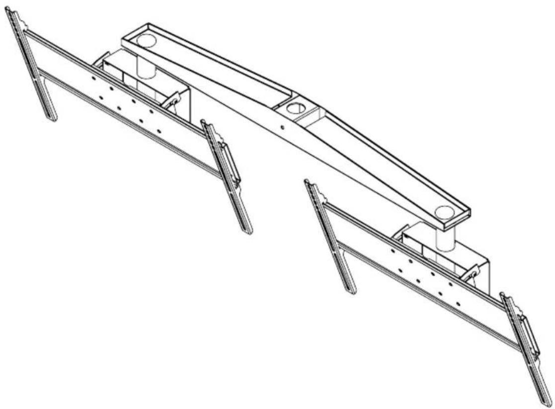
Installation and Assembly
MAX LOAD:
200LBS (90KG)

32" - 65"
(81 - 165 cm)

POSSIBLE INTERFERENCE WITH LARGER
DISPLAYS FACING THE SAME DIRECTION.
natural_image
Technical line drawing of a mechanical assembly with two views (top and side), no text or symbols present.| Parts List | |||
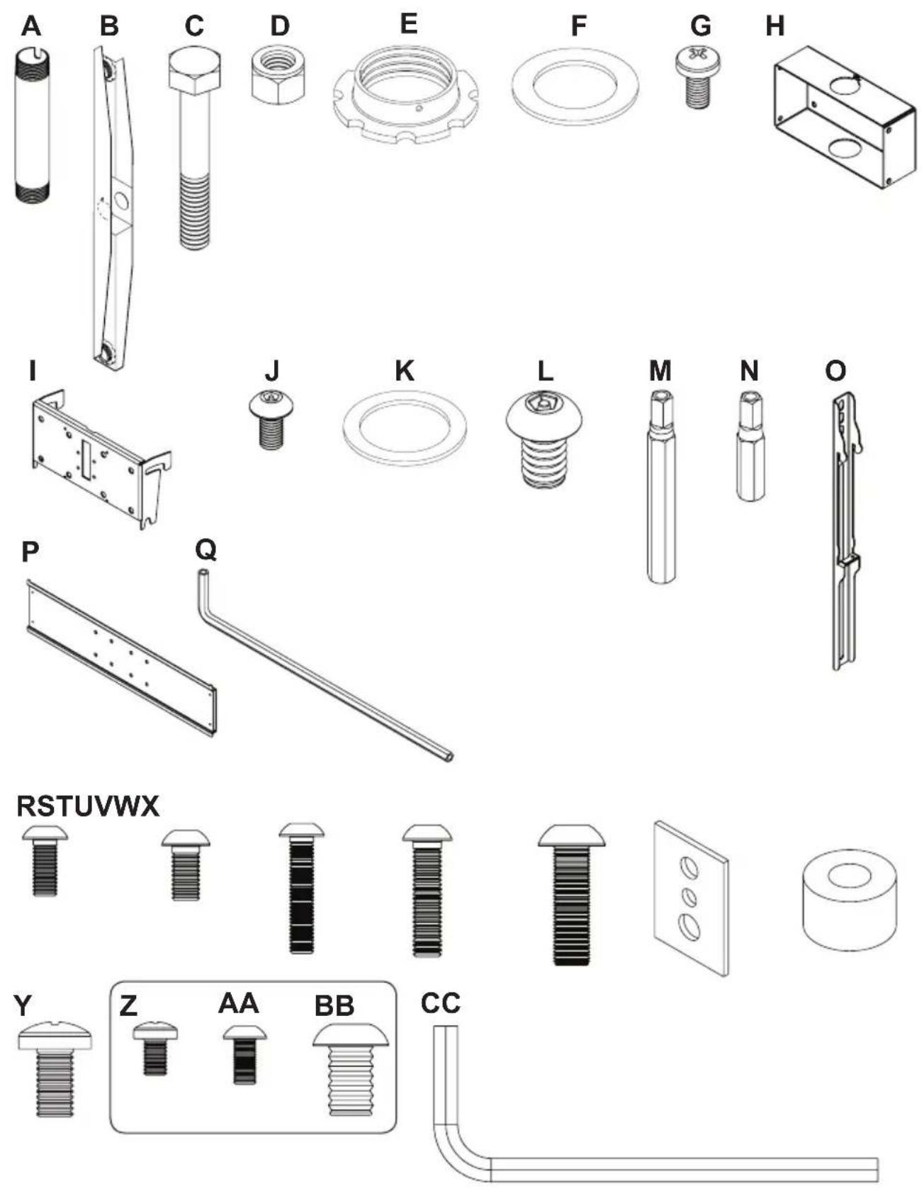
| Part Description Quantity Part Number | |||
| A tube 1.9 od, 6" for ext006 2 128-1094 | |||
| B dual cross support 44" assy, blk 1 139-1015 | |||
| C bolt 3/8-16x4.50" hxh, zb 1 520-9548 | |||
| D nut 3/8-16 nylock 1 530-9310 | |||
| E retaining collar, black finish 3 1800-375 | |||
| F wshr fiber 1.906idx 2.875 od x 0.062 1 540-9431 | |||
| G scr tap m5 x .8 x 10mm typ f pan phl zb 1 520-9250 | |||
| H ceiling arm box, blk 2 201-1062 | |||
| I plasma/lcs tilt brkt w/logo, blk | 2 200-1552 | ||
| J scr tap m5 x .8 x 10mm f penta pin blk | 8 | 505-9010 | |
| K wshr fbr 2.125idx2.875odx.062 | 2 540-9432 | ||
| L scr blt m10 x 1.5 x 15mm penta-pin blk 16 | 520-9263 | ||
| M M10 x 2" tool driver penta pin | 2 | 520-9260 | |
| N M5 x 1" tool driver penta pin | 2 520-9249 | ||
| O smart flt 18" slim sec bkt asy, blk | 4 | 201-1511 | |
| P large universal plp plate blk | 2 | 201-1110 | |
| Q 4mm allen wrench | 1 560-9646 | ||
| R M5 x 12mm skt pin, blk | 8 520-1064 | ||
| S M6 x 12mm skt pin, blk | 8 520-1050 | ||
| T scr bolt M5 x 0.8 x 25mm skt pin | 8 | 520-1122 | |
| U M6 x 25mm skt pin, blk | 8 | 520-1211 | |
| V scr blt M8 x 25mm skt pin btn, blk | 8 | 520-1101 | |
| W 3/4" wide multi washer, blk | 8 | 580-1398 | |
| X spacer .344 id x .75 od x .5 ht, blk | 8 540-1059 | ||
| Y scr bolt M8 x 12mm skt pin btn, blk | 8 520-1724 | ||
| Z M5 x .8 x 8mm pan phl type-f, blk | 8 520-1167 | ||
| AA scr bolt m5 x .8 x 10mm skt pin | 8 | 520-1063 | |
| BB scr bolt M10 x .5 x 15mm rnd skt blk | 8 | 520-9262 | |
| CC 6mm allen wrench | 2 560-9716 | ||
Z, AA, AND BB HARDWARE OPTIONAL.
DISPLAYS NOT INCLUDED.
1
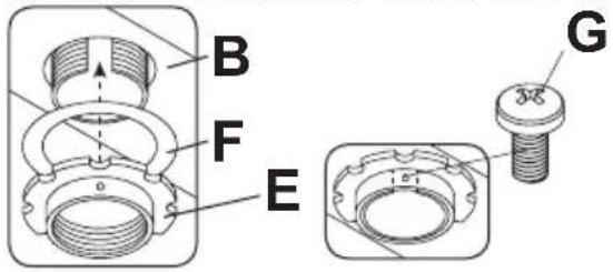
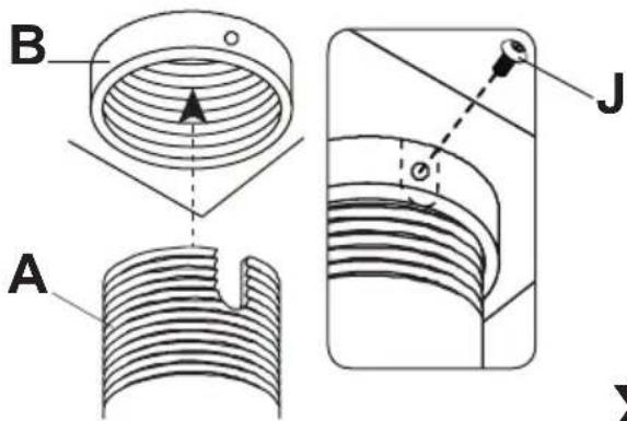
Slide dual cross support (B) onto the end of the extension pipe (sold separately). Rotate dual cross support (B) to desired positon. Drill 3/8" diameter hole through existing hole in dual cross support (B) into extension pipe (sold separately), repeat on oppostie side. Thread one 4.5" hex bolt (C) through the front of the dual cross support (B) and extension pipe. Secure .5" hex bolt (C) with one 3/8-16 nylock nut (D). Slide extension pipe fiber washer (F) onto the end of the extension pipe (sold separately) followed by the retaining collar. The Hole must line up with extension pipe (sold separately) slot. Secure retaining collar (E) with one M5 x 10mm screw (G).
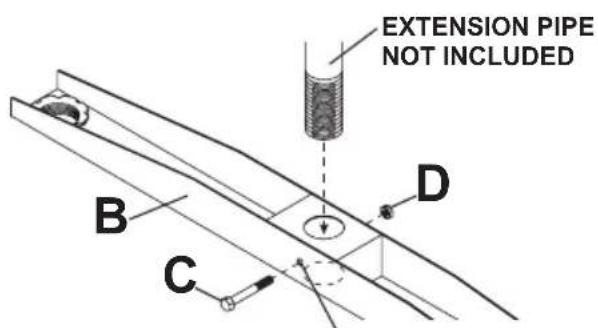
VIEW FROM BELOW DUAL CROSS SUPPORT (B)
USE HOLE AS GUIDE TO DRILL 3/8" HOLE THROUGH EXTENSION PIPE
2
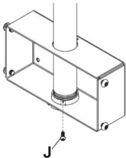
Thread two 6" extension columns (A) into both ends of the dual cross support (B). The holes in the dual cross support (B) must line up with the slots in the two 6" extension columns (A). Secure both 6" extension columns (A) using M5 x 10mm penta-pin screws (J).
3
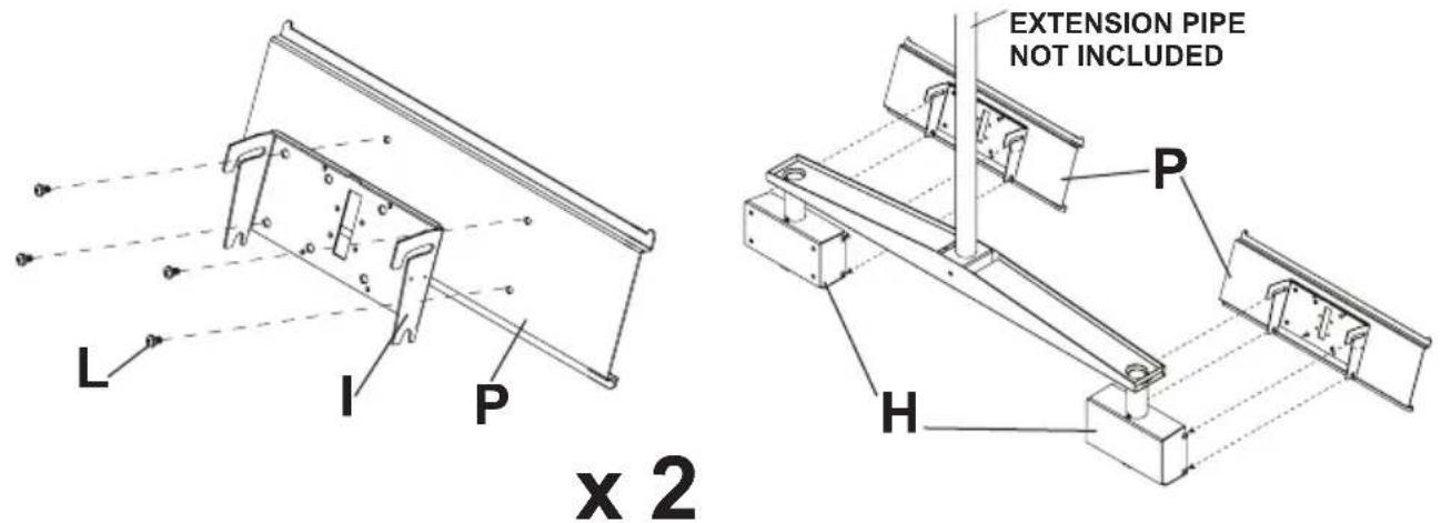
Leaving 14 " of space, thread eight M10 x 15mm penta-pin screws (L) into both ceiling arm boxes (H).
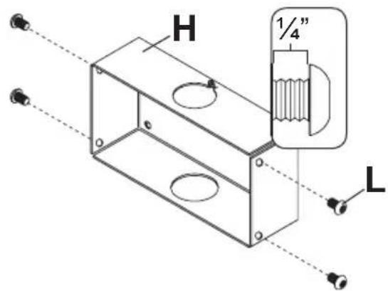
x 2 x 2
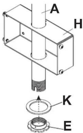
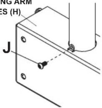
Slide ceiling arm boxes (H) onto the 6" extension columns (A) followed by two extension column fiber washers (K) and two retaining collars (E). The holes in retaining collars (E) must line up with the slots in the two 6" extension columns (A). Secure both ceiling arm boxes (H) using M5 x 10mm penta-pin screws (J).
natural_image
Technical line drawing of a mechanical assembly with a cylindrical component and mounting holes (no text or symbols)REAR VIEW OF CEILING ARM BOXES (H)
x 2
5
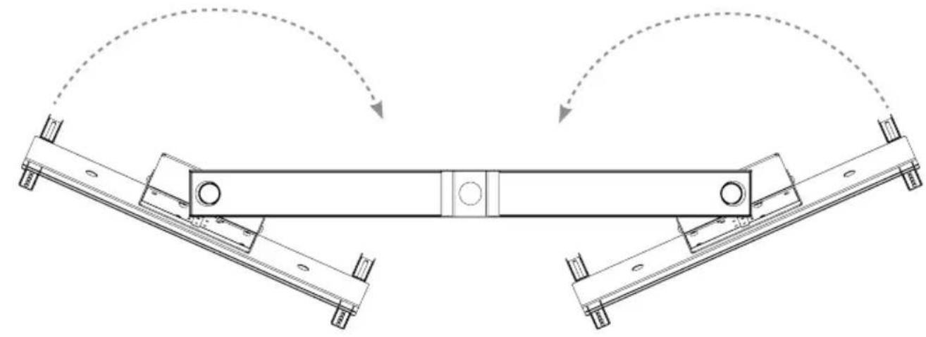
Secure PLP plates (P) to tilt brackets (I) using M10 x 15mm penta-pin screws (L). Hook PLP plates (P) to ceiling arm boxes (H). Tighten the M10 x 15mm penta-pin screws (L) to secure assembly.
6
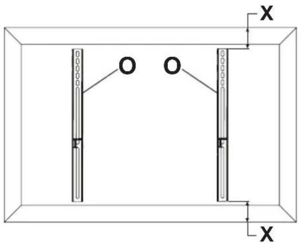
Center adapter brackets (O) vertically on back of display.
OPTIONAL
Use of spacers.
9
Hook displays onto PLP plates (P).
Adjust displays horizontally as needed.
natural_image
Pure technical diagram of a mechanical assembly with no text, numbers, or symbolsSecure displays by tightening adapter bracket screw.
10
Adjust displays as desired.
natural_image
Technical line drawing of a mechanical assembly with two symmetrical components and directional arrows indicating motion (no text or symbols)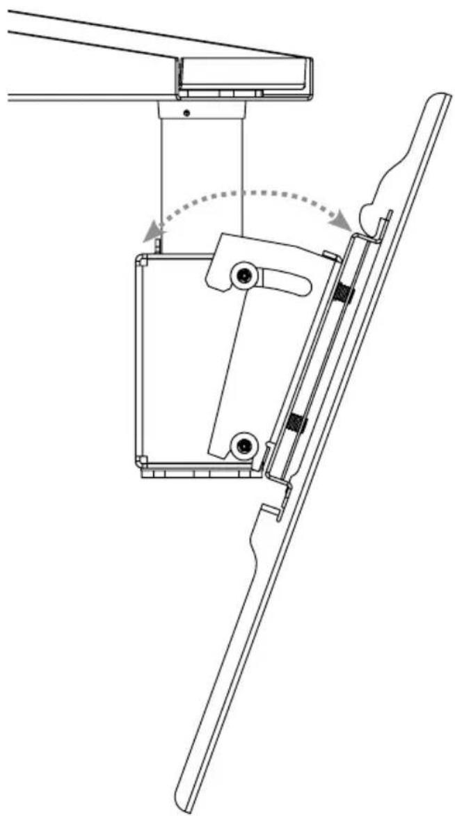
natural_image
Technical line drawing of a mechanical assembly with no visible text or symbolspeerless-AV®
Peerless-AV
2300 White Oak Circle
Aurora, IL 60502
Email: tech@peerlessmounts.com
Ph: (800) 865-2112
Fax: (800) 359-6500
www.peerless-av.com
© 2013, Peerless Industries, Inc.


Brand : Peerless-AV
Model : DST970X2
Category : Audiovisual support