Praga - Blender Xaoc - Free user manual and instructions
Find the device manual for free Praga Xaoc in PDF.


| Product Type | Voltage Controlled Stereo Mixing Console (Eurorack Module) |
| Brand | Xaoc Devices |
| Model | Praga (1967 rev. 1.0) |
| Eurorack Width | 20 hp |
| Power Consumption | +210 mA / -180 mA |
| Number of Channels | 4 |
| Volume Control Modes | Unipolar (green LED) and Bipolar (red LED) |
| Channel Muting | Clickless via short press; remote muting via expander |
| Pan Control | Manual and CV (-5V to +5V), 3 dB pan law |
| Auxiliary Sends | 2 stereo sends with stereo returns; post-fader |
| VCA Outputs | Direct per channel (unaffected by pan) |
| Main Outputs | 2 x Stereo Sum (L/R) |
| Signal Path | DC-coupled, super-clean, low distortion |
| Level Indicators | 5 LEDs per channel (-32, -20, -12, -6, 0 dB) |
| Expandability | Chain multiple units; optional Hrad expander for gate muting, inserts, CV aux |
| Protection | Reverse power protection; soft clipping on mix bus |
| Warranty | 1 year parts and labor (return-to-factory) |
| Recommended Attenuator Range | 50% – 80% to avoid distortion |
Frequently Asked Questions - Praga Xaoc
User questions about Praga Xaoc
0 question about this device. Answer the ones you know or ask your own.
Ask a new question about this device
Download the instructions for your Blender in PDF format for free! Find your manual Praga - Xaoc and take your electronic device back in hand. On this page are published all the documents necessary for the use of your device. Praga by Xaoc.
USER MANUAL Praga Xaoc
natural_image
Black-and-white photo of a person in uniform standing beside a vintage car with an airplane flying overhead (no visible text or symbols)OPERATOR'S MANUAL rev. 1967/1.0

PPA GGA
VOLTAGE
CONTROLLED
STEREO MIXING
CONSOLE
Model of 1967
SALUT
Thank you for purchasing this XaoC Devices product. Praga is an expandable four-channel voltage controlled mixer featuring a stereo mixing bus, two auxiliary sends with stereo returns, clickless muting, dedicated modes for unipolar and bipolar voltage control over volume, DC-coupling, and a super-clean signal path obtained via high-quality VCA and opamp chips.
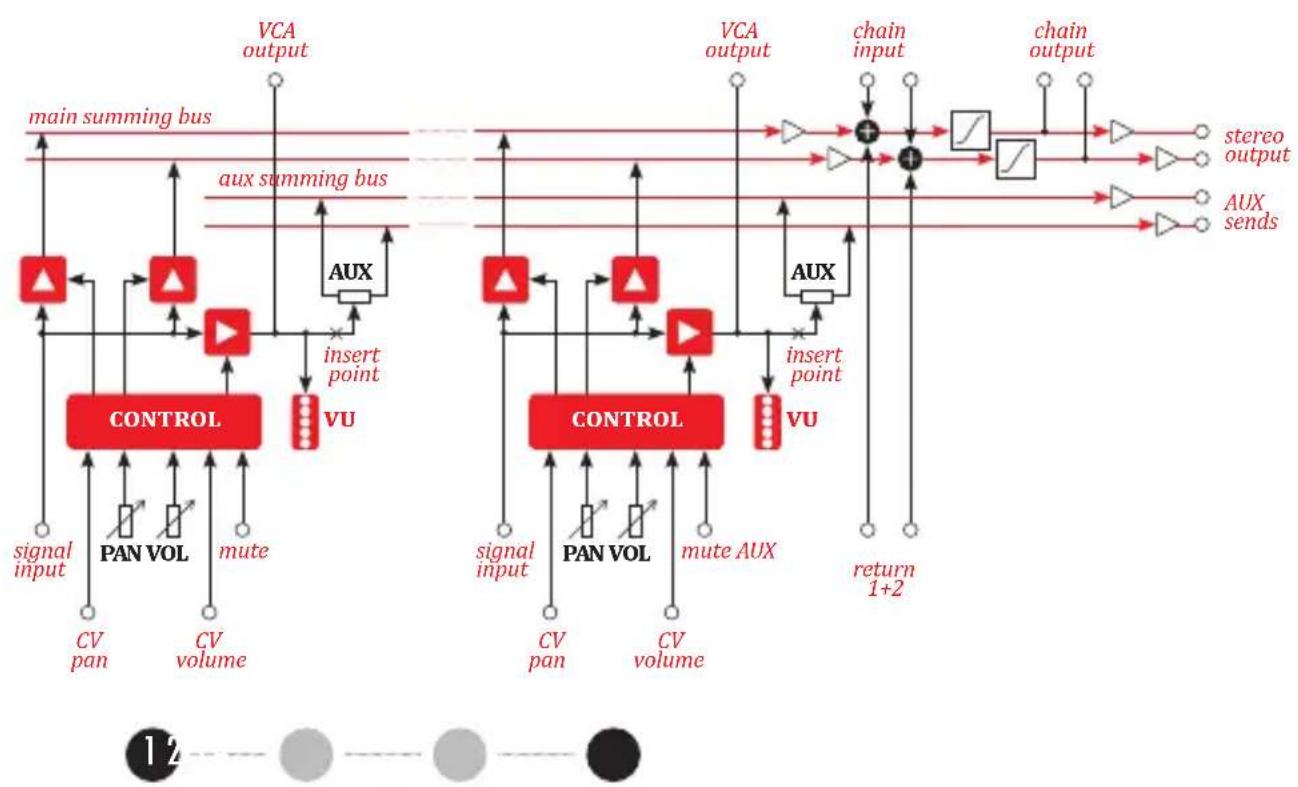
We have carefully crafted Praga's voltage control response to achieve what we believe to be the optimal user experience found in an eurorack mixer. The design features an elaborate control circuit that combines the internal voltages generated by the panel potentiometers with external CV over volume and pan (fig. 2). The result is a natural attenuator response that constrains VCA gain to an usable range while minimizing distortion.
INSTALLATION
The module requires 20hp worth of free space in the eurorack cabinet. The ribbon type power cable must be plugged into the bus board, paying close attention to polarity orientation. The red stripe indicates the negative 12V rail and should align with the dot, -12V or RED STRIPE marks on both the unit and the bus board. The module itself is protected against reversed power connection, however reversing the 16-pin header
MAY CAUSE SERIOUS DAMAGE to other components of your system by short-circuiting the +12V and +5V power rails. The module should be fastened by mounting the supplied screws before powering up. To better understand the device, we strongly advise the user to read through the entire manual before using the module.
MODULE OVERVIEW
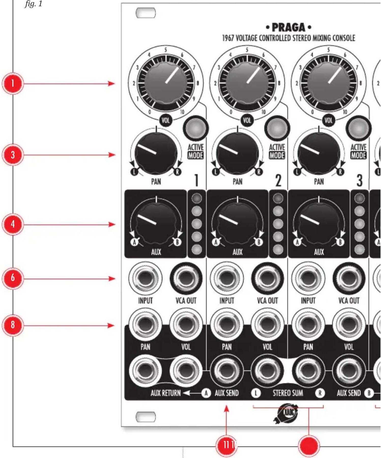
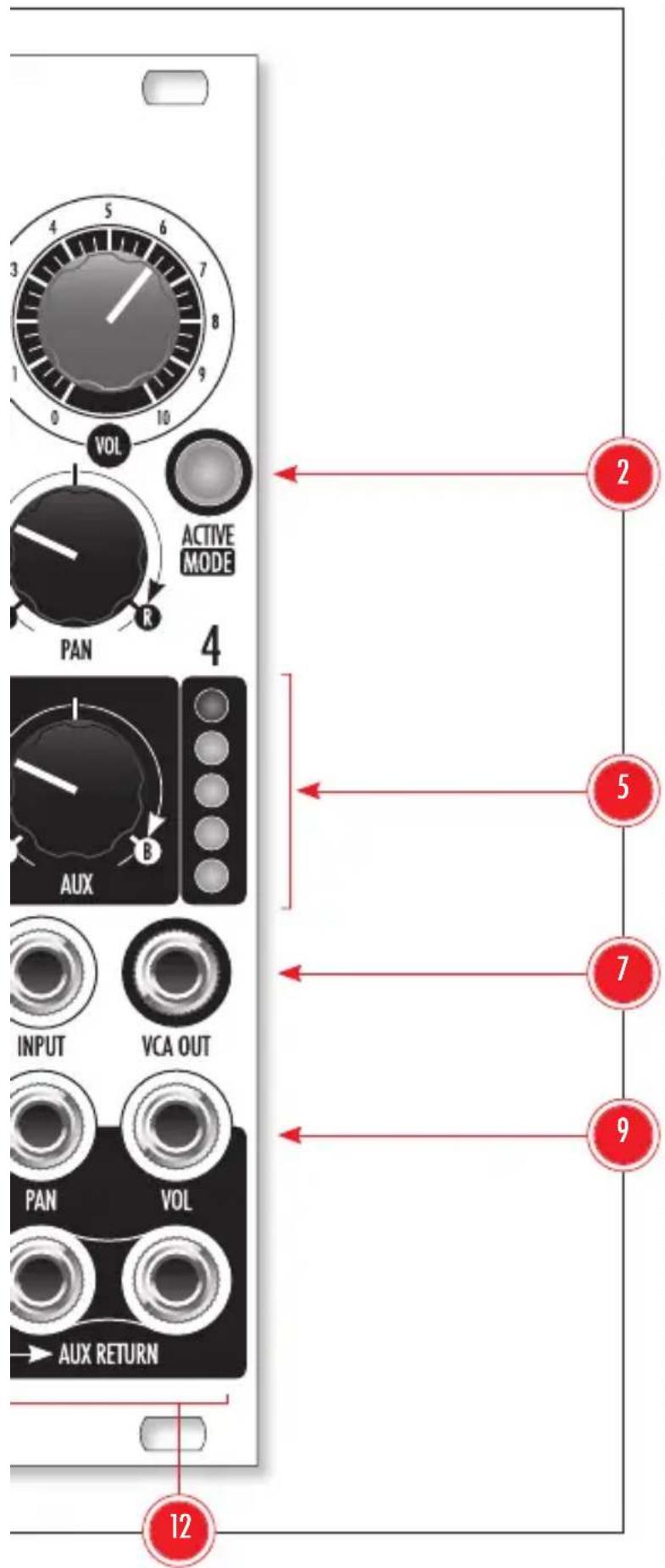
Praga's front-panel topology (see fig. 1) resembles a typical mixer with four identical channels. The VOL knobs 1 allow for manual control of each channel's respective level. Each channel's response depends on the selected control mode (see: 'Volume Control' later in this manual). The illuminated ACTIVE|MODE button 2 allows the user to mute the channel or switch between the two control modes. The PAN knob 3 adjusts the channel's position in the stereo panorama. The bipolar AUX knob 4 adjusts the amount of signal sent to either auxiliary channel. The five-bar LED level indicator 5 displays the channel's post-fader level, while the lower section contains the sockets for signal INPUT 6, direct VCA OUT 7, CV inputs for PAN 8 and VOL control 9. The bottom row of sockets is common to all four channels and consists of a pair of STEREO SUM outputs 10, two AUX SEND outputs 11 and two pairs of stereophonic AUX RETURN inputs 12.
VOLUME CONTROL
Praga offers two modes of combining incoming control voltages with attenuator settings. The mode is selected individually in each channel by a long press of the illuminated ACTIVE|MODE button. Mode switching is also possible while the channel is muted, confirmed by a short blink.
fig. 1
1. UNIPOLAR MODE
Unipolar mode (button lit green) is designed for unipolar control voltages commonly found in envelope generators. In this mode, the attenuator knob controls offsets to the incoming CV, allowing the dynamic response to CV to be retained regardless of attenuator position (fig. 4a, 4b). With attenuators at maximum, a CV of 8V opens the channels to 0dB, while closing the attenuators allows silencing the channels to -85dB. Control voltages above 8V are well-tolerated, however, the gain response is strongly tempered above 0dB, offering only up to +3dB so as to minimize distortion. This behavior affects the sound in a way similar to dynamic compression, however lowering the attenuators diminishes the effect, eventually bringing it down to a non-compressed operation.
2. BIPOLAR MODE
Bipolar mode (button lit red) is designed for bipolar control voltages commonly found in LFOs. In this mode, the attenuators act by scaling the CV together with an internally generated offset voltage. Therefore the depth of amplitude modulation (in dB) decreases as the channel is lowered. The response is optimized for control voltage in the range of -5V to +5V, whereby a fully-open attenuator offers 0dB at +5V and turning it fully counterclockwise yields an attenuation of -56dB with no modulation (see fig. 5a, 5b). Again, higher amplitudes of the CV are well-tolerated, however, the response is strongly compressed above 0dB.
flowchart
```mermaid
graph TD
    subgraph_Left_Summing_Bus["main summing bus"]
        A1["△"] --> B1["△"]
        A2["▲"] --> B2["▼"]
        A3["▲"] --> B3["▼"]
        A4["AUX"] --> B4["×"]
        B4 --> C1["VU"]
        C1 --> D1["PAN VOL"]
        C1 --> D2["PAN VOL"]
        C1 --> D3["PAN VOL"]
        C1 --> D4["PAN VOL"]
        C1 --> D5["PAN VOL"]
        C1 --> D6["PAN VOL"]
        C1 --> D7["PAN VOL"]
        C1 --> D8["PAN VOL"]
        C1 --> D9["PAN VOL"]
        C1 --> D10["PAN VOL"]
        C1 --> D11["PAN VOL"]
        C1 --> D12["PAN VOL"]
        C1 --> D13["PAN VOL"]
        C1 --> D14["PAN VOL"]
        C1 --> D15["PAN VOL"]
        C1 --> D16["PAN VOL"]
        C1 --> D17["PAN VOL"]
        C1 --> D18["PAN VOL"]
        C1 --> D19["PAN VOL"]
        C1 --> D20["PAN VOL"]
        C1 --> D21["PAN VOL"]
        C1 --> D22["PAN VOL"]
        C1 --> D23["PAN VOL"]
        C1 --> D24["PAN VOL"]
        C1 --> D25["PAN VOL"]
        C1 --> D26["PAN VOL"]
        C1 --> D27["PAN VOL"]
        C1 --> D28["PAN VOL"]
        C1 --> D29["PAN VOL"]
        C1 --> D30["PAN VOL"]
        C1 --> D31["PAN VOL"]
        C1 --> D32["PAN VOL"]
        C1 --> D33["PAN VOL"]
        C1 --> D34["PAN VOL"]
        C1 --> D35["PAN VOL"]
        C1 --> D36["PAN VOL"]
        C1 --> D37["PAN VOL"]
        C1 --> D38["PAN VOL"]
        C1 --> D39["PAN VOL"]
        C1 --> D40["PAN VOL"]
        C1 --> D41["PAN VOL"]
        C1 --> D42["PAN VOL"]
        C1 --> D43["PAN VOL"]
        C1 --> D44["PAN VOL"]
        C1 --> D45["PAN VOL"]
        C1 --> D46["PAN VOL"]
        C1 --> D47["PAN VOL"]
        C1 --> D48["PAN VOL"]
        C1 --> D49["PAN VOL"]
        C1 --> D50["PAN VOL"]
        C1 --> D51["PAN VOL"]
        C1 --> D52["PAN VOL"]
        C1 --> D53["PAN VOL"]
        C1 --> D54["PAN VOL"]
        C1 --> D55["PAN VOL"]
        C1 --> D56["PAN VOL"]
        C1 --> D57["PAN VOL"]
        C1 --> D58["PAN VOL"]
        C1 --> D59["PAN VOL"]
        C1 --> D60["PAN VOL"]
        C1 --> D61["PAN VOL"]
        C1 --> D62["PAN VOL"]
        C1 --> D63["PAN VOL"]
        C1 --> D64["PAN VOL"]
        C1 --> D65["PAN VOL"]
        C1 --> D66["PAN VOL"]
        C1 --> D67["PAN VOL"]
        C1 --> D68["PAN VOL"]
        C1 --> D69["PAN VOL"]
        C1 --> D70["PAN VOL"]
        C1 --> D71["PAN VOL"]
        C1 --> D72["PAN VOL"]
        C1 --> D73["PAN VOL"]
        C1 --> D74["PAN VOL"]
        C1 --> D75["PAN VOL"]
        C1 --> D76["PAN VOL"]
        C1 --> D77["PAN VOL"]
        C1 --> D78["PAN VOL"]
        C1 --> D79["PAN VOL"]
        C1 --> D80["PAN VOL"]
        C1 --> D81["PAN VOL"]
        C1 --> D82["PAN VOL"]
        C1 --> D83["PAN VOL"]
        C1 --> D84["PAN VOL"]
        C1 --> D85["PAN VOL"]
        C1 --> D86["PAN VOL"]
        C1 --> D87["PAN VOL"]
        C1 --> D88["PAN VOL"]
        C1 --> D89["PAN VOL"]
        C1 --> D90["PAN VOL"]
    end

    subgraph Right_Summing_Bus
        E["VCA output"] & F["VCA output"] & G["VCA output"] & H["VCA output"] & I["VCA output"] & J["VCA output"] & K["VCA output"] & L["VCA output"] & M["VCA output"] & N["VCA output"] & O["VCA output"] & P["VCA output"] & Q["VCA output"] & R["VCA output"] & S["VCA output"] & T["VCA output"] & U["VCA output"] & V["VCA output"] & W["VCA output"] & X["VCA output"] & Y["VCA output"] & Z["VCA output"] & AA["VCA output"] & AB["VCA output"] & AC["VCA output"] & AD["VCA output"] & AE["VCA output"] & AF["VCA output"] & AG["VCA output"] & AH["VCA output"] & AI["VCA output"] & AJ["VCA output"] & AK["VCA output"] & AL["VCA output"] & AM["VCA output"] & AN["VCA output"] & AO["VCA output"] & AP["VCA output"] & AQ["VCA output"] & AR["VCA output"] & AS["VCA output"] & AT["VCA output"] & AU["VCA output"] & AV["VCA output"] & AW["VCA output"] & AX["VCA output"] & AY["VCA output"] & AZ["VCA output"] & BA["VCA output"] & BB["VCA output"] & BC["VCA output"] & BD["VCA output"] & BE["VCA output"] & BF["VCA output"] & BG["VCA output"] & BH["VCA output"] & BI["VCA output"] & BJ["VCA output"] & BK["VCA output"] & BL["VCA output"] & BM["VCA output"] & BN["VCA output"] & BO["VCA output"] & BP["VCA output"] & BPV["VCA output"] & BPVI["VCA output"] & BPVVI["VCA output"] & BPVIVI["VCA output"] & BPVIVIVI["VCA output"] & BPVIVIVI["VCA output"] & BPVIVIVI["VCA output"] & BPVIVIVI["VCA output"] & BPVIVIVI["VCA output"] & BPVIVIVI["VCA output"] & BPVIVIVI["VCA output"] & BPVIVIVI["VCA output"] & BPVIVIVI["VCA output"] & BPVIVIVI["VCA output"] & BPVIVIVI["VCA output"] & BPVIWI-VB["VCA output"] & BPVIWI-VB["VCA output"] & BPVIWI-VB["VCA output"] & BPVIWI-VB["VCA output"] & BPVIWI-VB["VCA output"] & BPVIWI-VB["VCA output"] & BPVIWI-VB["VCA output"] & BPVIWI-VB["VCA output"] & BPVIWI-VB["VCA output"] & BPVIWI-VB["VCA output"] & BPVIWI-VW["BVCA output"] & BPVIWI-VW["BVCA output"] & BPVIWI-VW["BVCA output"] & BPVIWI-VW["BVCA output"] & BPVIWI-VW["BVCA output"] & BPVIWI-VW["BVCA output"] & BPVIWI-VW["BVCA output"] & BPVIWI-VW["BVCA output"] & BPVIWI-VW["BVCA output"] & BPVIWI-VW["BVCCA OUT BVC power supply 2x2x2x2x2x2x2x2x2x2x2x2x2x2x2x2x2x2x2x2x2x2x2x2x2x2x2x2x2x2x2x2x2x2x2x2x2x2x2x2x2x2x2x2x2x2x2x2x2x2x2a<br>    subgraph Control_Bus[CONTROL_Bus"]
            BND["signal input: CV pan, CV volume: CV pan, CV volume: CV volume, CV volume: CV volume, CV volume: CV volume, CV volume: CV volume, CV volume: CV volume, CV volume: CV volume, CV volume: CV volume, CV volume: CV volume, CV volume: CV volume, CV volume: CV volume, CV volume: CV volume, CV volume: CV volume, CV volume: CV volume, CV volume: CV volume, CV volume: CV volume, CV volume: CV volume, CV volume: CV volume, CV volume, CV volume: CV volume, CV volume: CV volume, CV volume: CV volume, CV volume: CV volume, CV volume: CV volume, CV volume: CV volume, CV volume: CV volume, CV volume: CV volume, CV volume: CV volume, CV volume: CV volume, CV volume: CV volume, CV volume: CV volume, CV volume: CV volume, CV volume: CV volume, CV volume: CV volume, CV volume: CV volume, CFV_PA_VOUT<br>    end<br>    subgraph Control_Cus[CONTROL_Cus"]
            ABD["△"] --> BBD["△"]
fig. 2
CHANNEL MUTING
Regardless of the current mode, a short-press on the ACTIVE|MODE button silences the corresponding channel. This state is indicated by the deactivation of the corresponding LED. Clickless action is achieved by introducing a few-millisecond fade-out to near -90dB. Pressing the button again brings the channel back through a similar clickless fade-in and reactivates the LED.
The operation of mutes can be controlled remotely through the expander pins at the back of the unit. The planned Hrad expansion module offers four gate inputs for automated channel muting.
PAN CONTROL
Praga offers both manual and CV control over the position of each channel in the output stereo panorama. The PAN knobs act as offsets to the PAN input control voltages which are expected in the range of -5V to +5V. The response of the combined controls provides equal loudness in a near-field monitoring setup (3dB pan law), however as channel gain approaches 0dB, the response is slightly compressed so as to prevent an increase of loudness (see fig. 6).
VCA OUTPUTS
A direct VCA OUT on each channel uses a separate VCA chip to provide a pure copy of the
attenuated signal unaffected by the PAN control. The purpose of these outputs is to offer individual mix components for multitracking, as well as to offer insert functionality with the Hrad expander.
AUXILIARY OUTPUTS
Two AUX SEND outputs, together with two pairs of stereo AUX RETURN sockets allow the user to patch two send effects. A dedicated bipolar AUX knob in each channel allows for manual control of the sends. By turning the knob to the left or right of center, the signal is sent to auxiliary channel A or B respectively. Sends are post-fader only, as they are derived from the VCA OUT signals.
The expander header on the back of the module features insert points between each channel's VCA and the AUX selector to provide channel inserts and voltage control over the AUX level through dedicated Hrad inputs.
LEVEL INDICATORS AND MIXING BUS LEVELS
Each of Praga's channels features an individual post-fader level indicator. The five LEDs show the state of a standard volume detector with thresholds at -32dB, -20dB, -12dB, -6dB and 0dB referenced to a 10Vpp signal. Bear in mind that eurorack electronic circuits cannot handle voltages greater than 10V, therefore it is impossible to mix four signals of 10Vpp without serious distortion.
It is recommended to keep your attenuators between 50% and 80% of the full range (un-
less your sources are very quiet). The mixing bus in Praga features a soft clipping circuit that offers a gentle overdrive for signals exceeding 16Vpp. This solution prevents the harsh sounding distortion resulting from hard clipping should the sum of your signals exceed the dynamic range of the output stage. Additional control over the sum level is offered by the Hrad expander at its dedicated STEREO SUM outputs.
CHAINING MULTIPLE UNITS
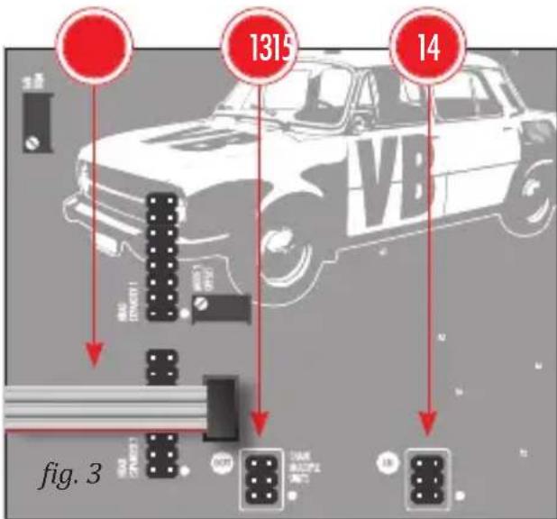
Multiple Praga units may be chained to provide a cascaded sub-mix setup such that the content of the mix bus of all upstream units is injected 1:1 into the mix bus of every subsequent unit appearing at its STEREO SUM outputs. The chaining headers at the back of the module should be connected with a 6-pin ribbon cable ⑮ so that the OUT header ⑬ of the preceding unit goes into the IN header ⑭ of the following unit (fig. 3). The IN header of the first unit and the OUT header of the last unit should remain unconnected.
CONTROL CHARACTERISTICS
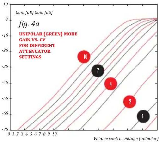
line
| Point | Volume control voltage (unipolar) | Gain [dB] | |-------|-----------------------------------|-----------| | 1 | ~10 | ~-60 | | 2 | ~15 | ~-50 | | 4 | ~20 | ~-40 | | 7 | ~25 | ~-30 | | 10 | ~30 | ~-20 |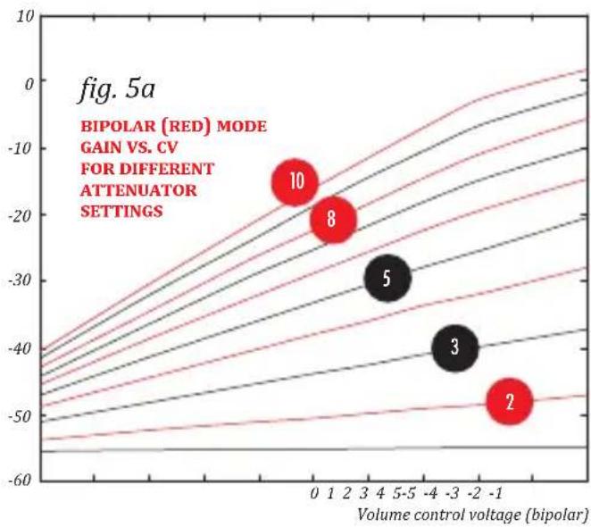
line
| Volume control voltage (bipolar) | Gain | | -------------------------------- | ---- | | 0 | -15 | | 1 | -20 | | 2 | -25 | | 3 | -30 | | 4 | -35 | | -1 | -50 |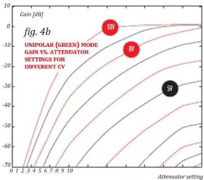
line
| Attenuator setting | Gain [dB] (5V) | Gain [dB] (8V) | Gain [dB] (10V) | | ------------------ | -------------- | -------------- | --------------- | | 10 | -30 | -10 | 0 |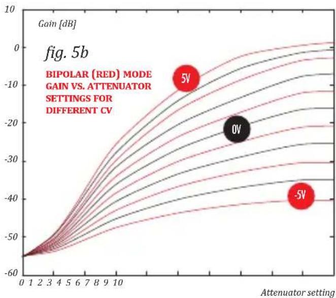
line
| Attenuator setting | Gain [dB] (5V) | Gain [dB] (0V) | Gain [dB] (-5V) | | ------------------ | -------------- | -------------- | --------------- | | 0 | -60 | -60 | -60 | | 10 | -10 | -20 | -30 |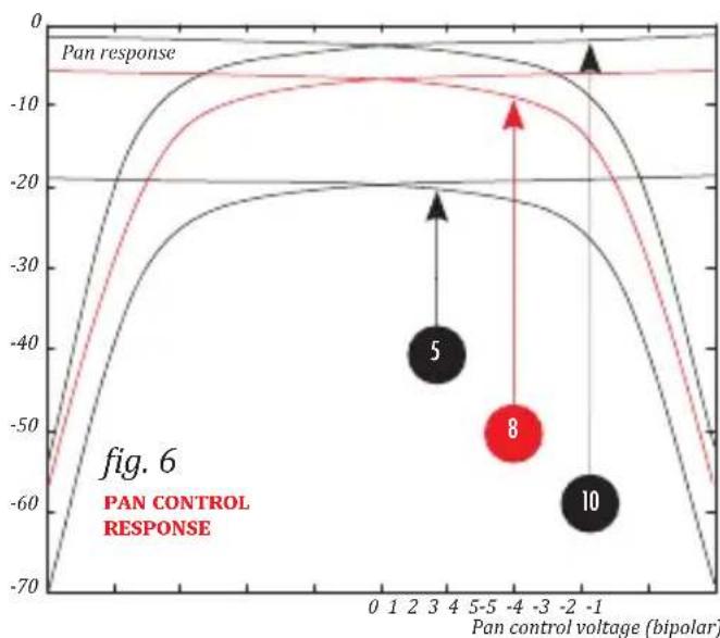
line
| Pan control voltage (bipolar) | Pan response | | ----------------------------- | ------------ | | 3 | -40 | | 4 | -20 | | -4 | -10 | | -1 | -60 |WARRANTY TERMS
XAOC DEVICES WARRANTS THIS PRODUCT TO BE FREE OF DEFECTS IN MATERIALS OR WORKMANSHIP, AND TO CONFORM WITH THE SPECIFICATIONS AT THE TIME OF SHIPMENT FOR A PERIOD OF ONE YEAR FROM THE DATE OF PURCHASE. DURING THAT PERIOD ANY MALFUNCTIONING OR DAMAGED UNITS WILL BE REPAIRED, SERVICED, AND CALIBRATED ON A RETURN-TO-FACTORY BASIS. THIS WARRANTY DOES NOT COVER ANY PROBLEMS RESULTING FROM DAMAGES DURING SHIPPING, INCORRECT INSTALLATION OR POWER SUPPLY, IMPROPER WORKING ENVIRONMENT, ABUSIVE TREATMENT OR ANY OTHER OBVIOUS USER-INFLICTED FAULT.
LEGACY SUPPORT
IF SOMETHING WENT WRONG WITH A XAOC PRODUCT AFTER THE WARRANTY PERIOD IS OVER, NO NEED TO WORRY, AS WE'RE STILL HAPPY TO HELP! THIS APPLIES TO ANY DEVICE, WHEREVER AND WHENEVER ORIGINALLY ACQUIRED. HOWEVER, IN SPECIFIC CASES, WE RESERVE THE RIGHT TO CHARGE FOR LABOR, PARTS AND TRANSIT EXPENSES WHERE APPLICABLE.
RETURN POLICY
THE DEVICE INTENDED FOR REPAIR OR REPLACEMENT UNDER WARRANTY NEEDS TO BE SHIPPED IN THE ORIGINAL PACKAGING ONLY, SO PLEASE KEEP IT JUST IN CASE. ALSO, A FILLED RMA FORM MUST BE INCLUDED. XAOC DEVICES CAN NOT TAKE ANY RESPONSIBILITY FOR DAMAGES CAUSED DURING TRANSPORT. PRIOR TO SENDING US ANYTHING, PLEASE CONTACT US AT SUPPORT@XAOCDEVICES.COM. NOTE THAT ANY UNSOLICITED PARCEL WILL BE REJECTED AND RETURNED!
GENERAL INQUIRIES
FOR USER FEEDBACK SUGGESTIONS, DISTRIBUTION TERMS, AND JOB POSITIONS FEEL FREE TO CONTACT XAOC DEVICES AT INFO@XAOCDEVICES.COM. PLEASE VISIT THE XAOCDEVICES.COM FOR INFORMATION ABOUT THE CURRENT PRODUCT LINE, USER MANUALS, FIRMWARE UPDATES, TUTORIALS, AND MERCHANDISE.
WORKING CLASS ELECTRONICS

ALL RIGHTS RESERVED. CONTENT COPYRIGHT © 2017 XAOC DEVICES. COPYING, DISTRIBUTION OR ANY COMMERCIAL USE IN ANY WAY IS STRICTLY PROHIBITED AND REQUIRES THE WRITTEN PERMISSION BY XAOC DEVICES. SPECIFICATIONS ARE SUBJECT TO CHANGE WITHOUT PRIOR NOTICE.
MAIN FEATURES
Intuitive volume control behaviour
Voltage control over volume and pan
Dedicated modes for unipolar and bipolar voltage control over volume
DC-coupled signal path
Channel level indicators
Two auxiliary sends with stereo returns
Clickless channel muting
Expandable by chaining more units and optional Hrad expander module
TECHNICAL DETAILS
Eurorack synth compatible
20hp, skiff friendly
Current draw: +210mA/-180mA
Reverse power protection
- PPA GGA
- SALUT
- INSTALLATION
- MODULE OVERVIEW
- VOLUME CONTROL
- UNIPOLAR MODE
- BIPOLAR MODE
- CHANNEL MUTING
- PAN CONTROL
- VCA OUTPUTS
- AUXILIARY OUTPUTS
- LEVEL INDICATORS AND MIXING BUS LEVELS
- CHAINING MULTIPLE UNITS
- CONTROL CHARACTERISTICS
- WARRANTY TERMS
- LEGACY SUPPORT
- RETURN POLICY
- GENERAL INQUIRIES
- WORKING CLASS ELECTRONICS
- MAIN FEATURES
- TECHNICAL DETAILS
Brand : Xaoc
Model : Praga
Category : Blender