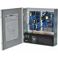
ReServ2 - Inverter Altronix - Free user manual and instructions
Find the device manual for free ReServ2 Altronix in PDF.


| Product Type | Inverter / Uninterruptible Power Supply (UPS) |
| Brand | Altronix |
| Model | ReServ2 |
| Dimensions (H x W x D) | 12.5 x 7.0 x 5.0 inches (318 x 178 x 127 mm) |
| Weight | 14.5 lbs (6.6 kg) |
| Input Voltage | 120 VAC, 60 Hz |
| Output Voltage | 120 VAC ± 5%, Pure Sine Wave |
| Output Power | 1500 VA / 1200 W |
| Battery Type | Sealed Lead-Acid (SLA), maintenance-free |
| Battery Capacity | 12V, 9 Ah |
| Typical Backup Time (Full Load) | Approx. 10 minutes at 1200W |
| Surge Protection | Yes, 300 joules |
| Number of Outlets | 4 x NEMA 5-15R (battery backup), 2 x surge-only |
| Indicators | LED status indicators: power, battery, fault |
| Alarms | Audible alarm: low battery, overload, fault |
| Communication Port | USB (HID) for monitoring |
| Operating Temperature | 32°F to 104°F (0°C to 40°C) |
| Maintenance | Keep clean and dry; check battery terminals annually; replace battery every 3-5 years |
| Safety Certifications | UL 1778, CSA, FCC Class B |
| Warranty | 2 years limited |
Frequently Asked Questions - ReServ2 Altronix
User questions about ReServ2 Altronix
0 question about this device. Answer the ones you know or ask your own.
Ask a new question about this device
Download the instructions for your Inverter in PDF format for free! Find your manual ReServ2 - Altronix and take your electronic device back in hand. On this page are published all the documents necessary for the use of your device. ReServ2 by Altronix.
USER MANUAL ReServ2 Altronix
- Twelve (12) true sine wave regulated 24VAC outputs and four (4) regulated 12VDC outputs.
- 4A total supply current @ 24VAC and 2A total supply current @ 12VDC.
- PTC protected power-limited outputs.
ReServ2
- Sixteen (16) true sine wave regulated 24VAC outputs.
- 4A total supply current.
- PTC protected power-limited outputs.
ReServ3
- Sixteen (16) regulated 12VDC outputs.
- 8A total supply current.
- PTC protected power-limited outputs.
Overview:
Altronix ReServ Video Surveillance UPS units are designed to provide power for 24VAC and/or 12VDC cameras during normal or power outage conditions.
True sine wave regulated AC outputs and/or regulated DC outputs.
ReServ Series Video Surveillance UPS Configuration Reference Chart:
| Altronix Model Number | Output/Supply Current (A) | Ambient Temperature | Input Rating | PTC Protected Power-Limited Outputs | 24VAC Outputs | 12VDC Outputs | Agency Listings | UL Listings and File Numbers |
| ReServ1 | 24VAC @ 4A (100VA) & 12VDC @ 2A | -33° to 30°C | 115VAC 60Hz, 3.5A | 16 12 | 4 |  | UL File # E329542 UL 60950-1 UL/CUL Listed for Information Technology Equipment. | |
| 24VAC @ 3.5A (85VA) & 12VDC @ 2A | -33° to 42°C |  | ||||||
| ReServ2 | 24VAC @ 4A (100VA) | -33° to 30°C | 115VAC 60Hz, 3.5A | 16 16 | - |  | ||
| 24VAC @ 3.5A (85VA) | -33° to 42°C | |||||||
| ReServ3 | 12VDC @ 8A -33° to 42°C | 115VAC 60Hz, 3.5A | 16 | - | 16 | |||
Specifications:
Output:
- PTC protected power-limited outputs rated @ 1A.
Battery Backup:
• Built-in charger for sealed lead acid or gel type batteries.
• Automatic switchover to stand-by battery when AC fails.
Supervision:
- AC fail supervision (form "C" contacts).
- Low battery supervision (form "C" contacts).
Visual & Audio Indicators:
• AC/DC power LED indicators.
- Individual power output LED indicators.
- Low voltage input and Shutdown LED indicators.
• Audio AC Fail and Battery Fail indicator.
Additional Features:
- True sine wave regulated AC outputs (ReServ1 & ReServ2). Regulated DC outputs (ReServ1 & ReServ3).
- Unit maintains camera synchronization.
- Ease of installation saves time and eliminates costly labor.
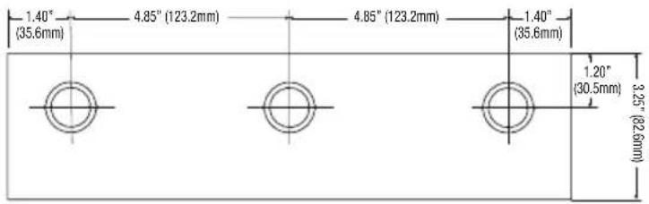
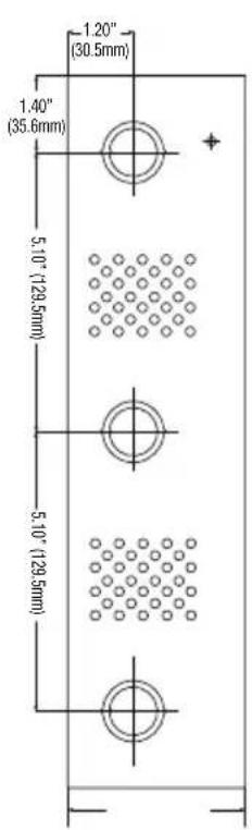
Enclosure Dimensions (H x W x D approximate): 13.5" x 13" x 3.25" (342.9mm x 330.2mm x 82.6mm)
• Enclosure accommodates up to two (2) 12VDC/7AH batteries.
Stand-by Specifications:
| Stand-by Batteries | ReServ1 - 4A (100VA) load at 24VAC and 2A load at 12VDC max. ReServ2 - 4A (100VA) max. load at 24VAC ReServ3 - 8A (100VA) max. load at 12VDC |
| Two (2) 12VDC/7AH 45 minutes | |
| Two (2) 12VDC/12AH 90 minutes |
*When using 12AH batteries or larger a separate UL Listed battery enclosure must be installed.
Optional UL Listed battery enclosure must be mounted adjacent to the power supply via Class 1 wiring methods.
Installation Instructions:
This installation should be made by qualified service personnel and should conform to all local codes and in accordance with the National Electrical Code. Product is intended for indoor use only. This product contains no serviceable parts.
- Mount unit in the desired location. Mark and predrill holes in the wall to line up with the top two keyholes in the enclosure. Install two upper fasteners and screws in the wall with the screw heads protruding. Place the enclosure's upper keyholes over the two upper screws, level and secure. Mark the position of the lower two holes. Remove the enclosure. Drill the lower holes and install the two fasteners. Place the enclosure's upper keyholes over the two upper screws. Install the two lower screws and make sure to tighten all screws (Enclosure Dimensions, pg. 8). Secure enclosure to earth ground.
Note: This product needs to be secured to the building before operation.
- Connect AC power mains to the terminals marked [L & N] (Figs. 1-3, pg. 5-7).
Use 18 AWG or larger for all power connections (Battery, output) (Figs. 1-3, pg. 5-7).
Use 18 AWG to 22 AWG for power-limited circuits (AC Fail/Low Battery reporting) (Figs. 1-3, pg. 5-7).
Note: A readily accessible disconnect device shall be incorporated in the building installation wiring.
-
The LEDs on the power supply board will illuminate when AC power is present.
-
Measure output voltage before connecting cameras/devices to outputs. This helps avoiding potential damage.
-
ReServ3 only - Adjust voltage for every two (2) outputs using the corresponding trimpot(s) on the board prior to connecting devices.
-
Connecting cameras/devices:
ReServ1 - Connect 12VDC cameras/devices to the terminals marked [P 1-4, N 1-4] (Fig. 1, pg. 5).
Connect 24VAC cameras/devices to the terminals marked [5-16] (Fig. 1, pg. 5).
ReServ2 - Connect 24VAC cameras/devices to the terminals marked [1-16] (Fig. 2, pg. 6).
ReServ3 - Connect 12VDC cameras/devices to the terminals marked [P 1-16, N 1-16] (Fig. 3, pg. 7).
- Connect batteries to the terminals marked [+BAT-] (Figs. 1-3, pg. 5-7).
Use two (2) 12VDC batteries connected in series for 24VDC operation (battery leads included).
Use batteries - Casil CA1270 (12V/7AH), Genesis NP7-12 (12V/7AH), Ultratech UT1270 (12V/7AH).
-
Connect appropriate signaling notification devices to AC FAIL & BAT FAIL (Figs. 1-3, pg. 5-7) supervisory relay outputs.
-
The power LEDs on the unit for Outputs 1-16 will illuminate when AC power is present (Figs. 1-3, pg. 5-7).
Note: If any of the power LEDs are not illuminated, the cause may be due to the following:
a. AC mains and battery fail.
b. One (1) or more power output PTCs are tripped due to a short circuit or overload condition.
c. Unit damaged/defective.
To reset the PTC:
-
Disconnect corresponding camera/device connected to terminals marked [1-16] (Figs. 1-3, pg. 5-7).
-
Eliminate the trouble condition (short circuit or overload).
-
Allow 1 minute for PTC to cool off (reset).
-
Connect corresponding cameras/devices to terminals marked [1-16] (Figs. 1-3, pg. 5-7).
-
Power LEDs will illuminate indicating power has been restored to outputs (Figs. 1-3, pg. 5-7).
WARNING: To reduce the risk of fire or electric shock, do not expose the unit to rain or moisture. This installation should be made by qualified service personnel and should conform to the National Electrical Code and all local codes.

The lightning flash with arrow head symbol within an equilateral triangle is intended to alert the user to the presence of an insulated DANGEROUS VOLTAGE within the product's enclosure that may be of sufficient magnitude to constitute an electric shock.

The exclamation point within an equilateral triangle is intended to alert the user to the presence of important operating and maintenance (servicing) instructions in the literature accompanying the appliance.

CAUTION
RISK OF ELECTRIC SHOCK
DO NOT OPEN

CAUTION: To reduce the risk of electric shock do not open enclosure.
There are no user serviceable parts inside.
Refer servicing to qualified service personnel.
LED Diagnostics:
Power Supply Board
| Red (DC) Green (AC1) Power Supply Status | |
| ON ON Normal operating condition. | |
| ON OFF Loss of AC. Stand-by battery supplying power. | |
| OFF ON No DC output. | |
| OFF OFF Loss of AC. Discharged or no stand-by battery. No DC output. | |
ReServ Board
| LED LED State | Unit Status | ||
| Output LEDs | ON – | Normal | operating condition. |
| – OFF | F Loss of 24VAC and/or 12VDC output power. | ||
| Low Battery | ON – | Stand-by batteries are low. | |
| – OFF | F Normal operating condition. | ||
| Shutdown | ON – | Loss of 24VAC and/or 12VDC output power. Discharged stand-by battery. | |
| – OFF | F Normal operating condition. | ||
Audio Signal Diagnostics:
ReServ Unit
| Audio Signal Unit Status | |
| Single Periodic Beep AC Fail. | |
| Double Periodic Beep Low Battery or No Battery. |
Terminal Identification:
Power Supply Board
| Terminal Legend | Function/Description |
| L, G, N Connect | 115VAC 60Hz to these terminals: L to hot, N to neutral. |
| - DC + 24VDC | non power-limited output. |
| AC FAIL NO, C, NC | Form “C” dry contacts used to instantaneously signal the loss AC to local annunciation devices, with AC present terminals marked NO and C are open, NC and C are closed.When loss of AC occurs terminals marked NO and C are closed, NC and C are open. |
| BAT FAIL NO, C, NC | Form “C” dry contacts used to signal low battery voltage or loss of battery voltage.Under normal conditions terminals marked NO and C are open, NC and C are closed.During a trouble condition terminals marked NO and C are closed, and NC and C are open. |
| + BAT - | Stand-by battery connections. Maximum charge current 0.7A. |
ReServ Board
| Terminal Legend | Function/Description |
| Input-24VDC + | 24VDC input from power supply board. |
| N, P 1-16 | 24VAC and/or 12VDC outputs. |
Fig. 1 - ReServ1

Fig. 2 - ReServ2

Fig. 3 - ReServ3

Enclosure Dimensions (H x W x D approximate):
13.5" x 13" x 3.25" (342.9mm x 330.2mm x 82.6mm)


Altronix is not responsible for any typographical errors.


Brand : Altronix
Model : ReServ2
Category : Inverter