
AL802ULADAJ - Inverter Altronix - Free user manual and instructions
Find the device manual for free AL802ULADAJ Altronix in PDF.


| Product Type | Power Supply / Charger with Battery Backup |
| Brand | Altronix |
| Model | AL802ULADAJ |
| Input Voltage | 115VAC, 60Hz, 2.5A |
| Output Voltage | 12VDC or 24VDC (selectable) |
| Output Current | 8A continuous @ 12VDC; 4A @ 24VDC |
| Battery Backup | Built-in charger for up to 12VDC / 7Ah sealed lead acid battery |
| Charging Current | 0.7A |
| Dimensions (H x W x D) | 15.5 x 12.5 x 4.5 inches |
| Weight | 12 lbs |
| Operating Temperature | 0°C to 49°C (32°F to 120°F) |
| LED Indicators | AC Power ON, Battery Low/Disconnected |
| AC Input | Detachable 6 ft. cord |
| DC Output | Screw terminals, Class 2 rated |
| Enclosure | Steel, black finish, lockable |
| Mounting | Wall mount |
| Certifications | UL 294, UL 1481, cUL, CE, RoHS |
| Warranty | Lifetime warranty |
| Maintenance | Periodic battery test and cleaning; keep vents clear |
| Safety Features | Overvoltage protection, short circuit protection, thermal overload |
| Spare Parts | Battery, fuse, transformer available from Altronix |
| Reparability | Field serviceable; contact Altronix for service |
Frequently Asked Questions - AL802ULADAJ Altronix
At 12VDC, it delivers up to 8A; at 24VDC, up to 4A.
Ensure polarity is correct. The built-in charger will maintain the battery.
Use UL-recognized battery for best performance.
It provides regulated power and battery backup for locks, panels, etc.
Normal operation: green ON, red OFF.
Ensure power is disconnected before changing voltage setting.
Install in a dry, ventilated area.
Contact Altronix for claim procedure.
Use appropriate screws (not included) for secure mounting.
If not, check fuse (internal). If battery LED is red, check battery connections and replace battery if needed.
User questions about AL802ULADAJ Altronix
0 question about this device. Answer the ones you know or ask your own.
Ask a new question about this device
Download the instructions for your Inverter in PDF format for free! Find your manual AL802ULADAJ - Altronix and take your electronic device back in hand. On this page are published all the documents necessary for the use of your device. AL802ULADAJ by Altronix.
USER MANUAL AL802ULADAJ Altronix
Installation Guide (See Application Guide for additional information)

Altronix®
AL802ULADAJ - NAC Power Extender
Overview:
The Altronix AL802ULADAJ is an extremely cost effective 8 amp remote power supply/battery charger. It may be connected to any 12 or 24 volt Fire Alarm Control Panel (FACP). Primary applications include Notification Appliance Circuit (NAC such as strobes and horns) expansion support to meet ADA requirements. It also provides auxiliary power to support system accessories. The unit delivers electronically regulated and filtered 24 volt power to Class B, Style W, Y or Class A, Style Z NAC loop circuits. Additionally, a separate 1.0A auxiliary output with reset for four (4)-wire smoke detectors is available. The 8 amp max. alarm current can be divided between the four (4) outputs for powering NAC devices. Each output is rated at 2.5 amp max., and can be independently programmed for Steady, Temporal Code 3 or Strobe Synchronization. All outputs may be programmed for Input to Output Follower Mode (output will follow input. i.e. March Time Input, March Time Output). In non-alarm condition independent loop supervision for Class A, Style Z and/or Class B, Style W, Y FACP NAC circuits is provided. In the event of a loop trouble, the FACP will be notified via the steered input (input 1 or input 2). In addition, there are common trouble output terminals [NC, C, NO] which are used to indicate general loop/system trouble. A common trouble input is provided for optional NC (normally closed) devices to report trouble to the FACP. Two (2) FACP signaling outputs can be employed and directed to control supervision and power delivery to any combination of the four (4) outputs.
Specifications:
Agency Listings:
- UL Listed Control Units for Fire Protective Signaling Systems (UL 864).
• MEA - NYC Department of Buildings Approved.
• CSFM - California State Fire Marshal Approved.
• FM - Factory Mutual Approved.
• NFPA 72 Compliant.
Input:
• Power input 120VAC 60 Hz, 5 amp.
- Two (2) Class A, Style Z or two (2) Class B, Style W, Y FACP inputs.
- Two (2) NC dry contact trigger inputs.
Output:
• Class 2 Rated power limited outputs.
• 24VDC @ 8 amp max total alarm current.
• 2.5 amp max current per output.
- Separate 1.0 amp auxiliary output.
- Programmable supervised indicating circuit outputs: Four (4) Class B, Style W, Y or Two (2) Class A, Style Z or One (1) Class A, Style Z and Two (2) Class B, Style W, Y (see Application Guide).
- Thermal and short circuit protection with auto reset.
Battery Backup:
• Built-in charger for sealed lead acid or gel type batteries.
- Automatic switchover to stand-by battery when AC Fails.
- Zero voltage drop when switching over to battery backup.
Supervision:
- AC fail supervision (form "C" contact, 1 amp / 28VDC). Factory set for 30 seconds with optional 2.5 to 3 hour delay setting (field selectable).
- Instant local AC trouble reporting relay (form "C" contact, 1 amp / 28VDC).
- Battery presence and low battery supervision (form "C" contact, 1 amp / 28VDC).
Visual Indicators:
- Input and output status LED indicators.
Special Features:
- 2-wire horn/strobe Sync mode allows audible notification appliances (horns) to be silenced while visual notification appliances (strobes) continue to operate.
- Temporal Code 3, Steady Mode, Input to Output Follower Mode (maintains synchronization of notification appliances circuit).
- Compatible with 12VDC or 24VDC fire panels.
- Output loop supervision steered to input 1 or input 2.
- Signal circuit trouble memory (helps identify intermittent loop problems).
- Common trouble input and output.
• Ground fault detection.
Added Features:
- Unit includes power supply, red enclosure, cam lock, and battery leads.
Enclosure Dimensions and Descriptions: AL802ULADAJ
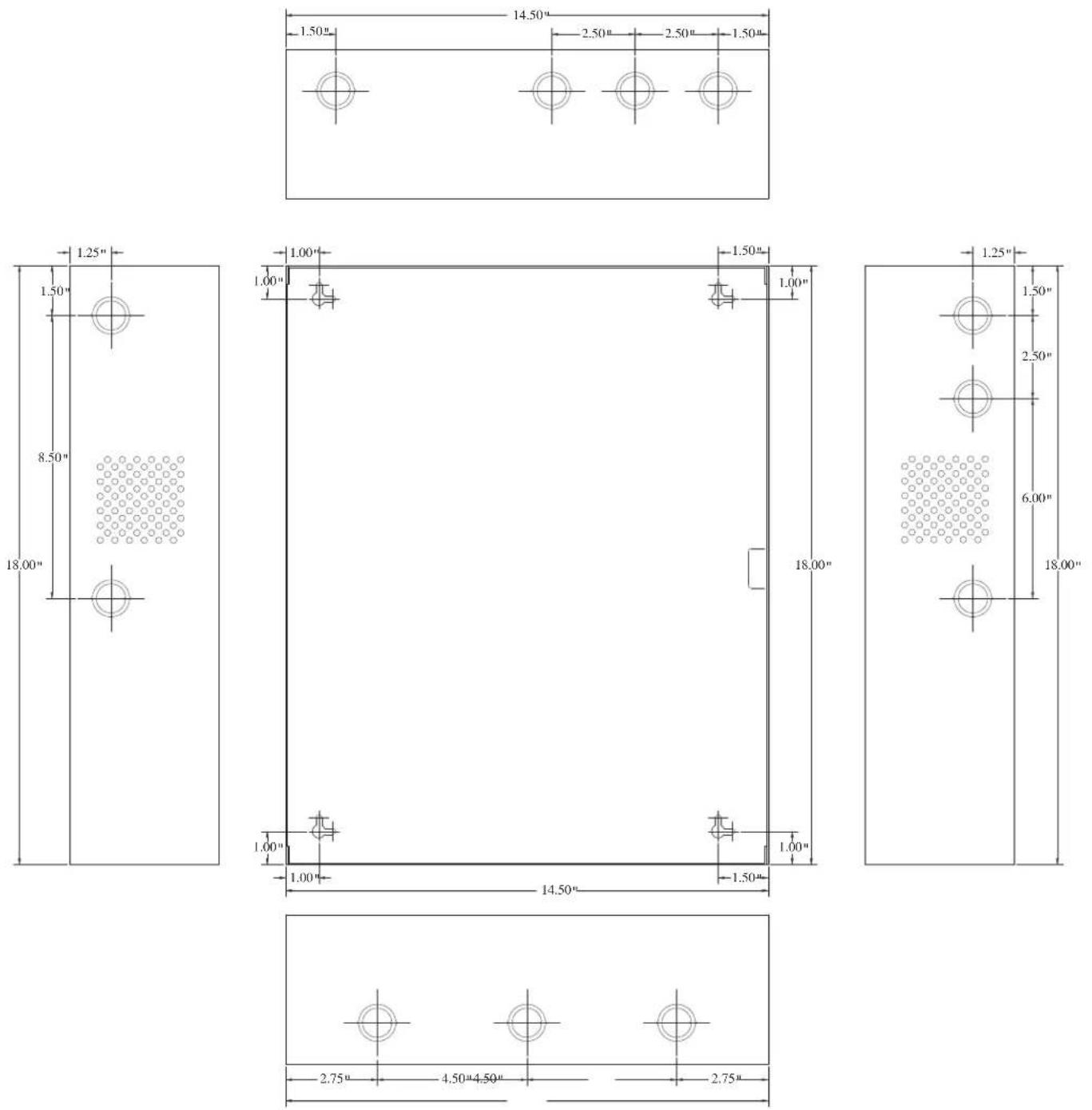
18"H x 14.5"W x 4.5"D
Product Weight:
19 lbs.
Power Supply Specifications:
| AC Input: | 120VAC 60Hz, 5 amp, supplied by a maximum 15 amp dedicated branch circuit. |
| Output: | Four (4) regulated supervised NAC output circuits, 24VDC, 2.5 amp maximum current. One (1) aux. special application 24VDC power output circuit 1 amp, non-supervised total output current must not exceed current 8 amp in Alarm Condition. |
| Battery: | Use two (2) 12VDC / 12AH or two (2) 12VDC / 7AH batteries connected in series. |
| Stand-by/Alarm Current Consumption: | 90mA/175mA |
| EOL Resistor (end of line): | 2.2K (2200 ohm), Altronix Model # AL-EOL22 (included). |
| Ground fault maximum test impedance: | 1000 ohm. |
Stand-by Specifications:
| Stand-by Batteries | Stand-by Time Total Amp/Minutes | Alarm Output Current | Aux. Output |
| 24VDC/7AH | 24 Hours | 8 amp/5 minutes | - |
| 24VDC/12AH(use two (2) 12VDC batteries in series) | 24 Hours | 8 amp/5 minutes | 50mA |
| 24VDC/36AH | 24 Hours | 8 amp/5 minutes | 1 amp |
Note: Unit is equipped with 1 amp max. auxiliary output: “AUX” will remain battery backed up during power outage. For loads connected to “AUX” please, refer to battery “Stand-by Specifications” above for ratings. When loads are connected to “AUX” output during alarm condition, the remaining outputs may, not exceed 8 amp total alarm current (example: AUX = 1 amp, outputs up to 7 amp).
Installation Instructions:
Wiring methods shall be in accordance with the National Electrical Code/NFPA 70/NFPA 72/ANSI, and with all local codes and authorities having jurisdiction.
Product is intended for indoor use only.
Carefully review:
Application Guide for AL602ULADAJ,AL802ULADAJ,AL1002ULADAJ
Power Supply Specifications (pg. 3)
Stand-by Specifications (pg. 3)
Output Programming Selection Table (pg. 4)
Sync Mode Selection Table (pg. 4)
Terminal Identification Table (pgs. 5-6)
LED Status Indication Table
(pg. 6)

-
Mount the unit in desired location. Mark and predrill holes in the wall to line up with the top two keyholes in the enclosure. Install two upper fasteners and screws in the wall with the screw heads protruding. Place the enclosure's upper keyholes over the two upper screws, level and secure. Mark the position of the lower two holes. Remove the enclosure. Drill the lower holes and install the two fasteners. Place the enclosure's upper keyholes over the two upper screws. Install the two lower screws and make sure to tighten all screws (Enclosure Dimensions, pg. 12). Secure enclosure to earth ground (Fig. 1, pg.3).
-
Connect the line (L), ground (G), and neutral (N) terminals to a separate unswitched AC circuit (120VAC, 60Hz) dedicated to the Fire Alarm System.
-
Measure output voltage before connecting devices. This helps avoid potential damage.
-
Connect battery to terminals marked [+ BAT -] on the Power Supply Board (battery leads included). Use two (2) 12VDC batteries connected in series.
-
Set output selection switches marked [OUT1 through OUT4] to follow corresponding input [IN1 & IN2] and desired output signal type (Output Programming Selection Table, pg. 4).
-
Connect FACP output to desired AL800LGK logic board inputs, and notification appliances to desired AL800LGK logic board outputs (see Application Guide).
Note: The 2-wire horn/strobe sync mode will only synchronize horns, horn/strobes, strobes with synchronization capability.
- For connection of smoke detectors, digital dialer (Optional Hookup Diagram, pg. 7).
Class A, Style Z Class B, Style W, Y, SW1 & SW2 Settings:
- For all Class B, Style W, Y, hookups SW1 & SW2 on the AL800LGK logic board must be open. For all Class A, Style Z hookups SW1 & SW2 on the AL800LGK logic board must be closed.
Output Programming Selection Table:
Outputs must be programmed independently (OUT1 - OUT4)
| Function | Switch Positions | Descriptions | |
| ON OFF | |||
| Input to Output Follower Mode 1 | 2, 3 | Output follows signal it receives from the corresponding input (i.e. FACP Sync module - maintains synchronization of notification appliance circuit). | |
| Temporal Code 3 Mode 3 1, 2 | Enables Temporal Code 3 signal generation output.This mode will accept a steady or a pulsing input. | ||
| Steady Mode 1, 2, 3 | A steady output signal will be generated.This mode will accept steady or pulsing input. | ||
For the above modes Dip Switch 4 determines which Input controls the corresponding output:
Switch 4 in the ON position causes output(s) to be controlled by input 1.
Switch 4 in the OFF position causes output(s) to be controlled by input 2.
(AL800LGK Board)
Output Dip Switches
Sync Mode Selection Table:

INPUT SELECT
TEMPORAL
STROBE SYNC
IN>OUT SYNC
| Function | Switch Positions | Descriptions | |
| ON | OFF | ||
| Amseco Sync Mode* | 1, 3,4 | 2 | This mode is designed to work with the Amseco series of horns, strobes, and horn/strobes to provide a means of synchronizing the Temporal-coded horns, synchronizing the flash timing of the strobe, and silencing the horns of the horn/strobe combination over a two-wire circuit while leaving strobes active. |
| Faraday Sync Mode* | 2, 4 | 1, 3 | This mode is designed to work with the Faraday series of horns, strobes, and horn/strobes to provide a means of synchronizing the Temporal-coded horns, synchronizing the flash timing of the strobe, and silencing the horns of the horn/strobe combination over a two-wire circuit while leaving strobes active. |
| Gentex® Sync Mode* Gentex is a registered trademark of Gentex Corporation. | 1, 2,3, 4 | This mode is designed to work with the Gentex® series of horns, strobes, and horn/strobes to provide a means of synchronizing the Temporal-coded horns, synchronizing the flash timing of the strobe, and silencing the horns of the horn/strobe combination over a two-wire circuit while leaving strobes active. | |
| System Sensor® Sync Mode* System Sensor is a registered trademark of Honeywell. | 1, 2, 4 | 3 | This mode is designed to work with the System Sensor® series of horns, strobes, and horn/strobes to provide a means of synchronizing the Temporal-coded horns, synchronizing the one-second flash timing of the strobe, and silencing the horns of the horn/strobe combination over a two-wire circuit while leaving strobes active. |
| CooperWheelock® Sync Mode* CooperWheelock is a registered trademark of CooperWheelock. | 2, 3, 4 | 1 | This mode is designed to work with the CooperWheelock series of horns, strobes, and horn/strobes to provide a means of synchronizing the Temporal-coded horns, synchronizing the one-second flash timing of the strobe, and silencing the horns of the horn/strobe combination over a two-wire circuit while leaving strobes active. |
*Note: The AL802ULADAJ will only synchronize horns, horn/strobes and strobes that contain synchronization capability. Contact signal manufacturer for more detailed info. The same synchronization mode must be selected for all outputs.
Note: It is required to control visual notification appliances (strobes) via input 1 [IN1] and audible notification appliances (horns) via input 2 [IN2]. This allows audible notification appliances (horns) to be silenced while visual notification appliances (strobes) continue to operate.
Amount of Notification Appliances per unit:
*Not to exceed a maximum of 2.5 amp per NAC
Terminal Identification Table:
AL800LGK Logic Board
| TerminalLegend | Function/Description |
| IN1+, IN1-IN2+, IN2-(Supervised) | These terminals connect to the 12VDC or 24VDC FACP notification appliance circuit outputs. (Class A, Style Z or Class B, Style W, Y) Input trigger voltage is 8-33VDC @ 5mA min. Terminal polarity is shown in alarm condition. During an alarm condition these inputs will cause the selected outputs chosen to drive notification appliances. The designated outputs are set by output switches [OUT1 through OUT4] (Output Programming Selection Table, pg. 4). A trouble condition on an output loop will cause the corresponding input to trip the FACP by opening the FACP loop. An alarm condition will always override trouble to drive notification appliances. |
| RET1+, RET1-RET2+, RET2-(Supervised) | For (Class A, Style Z hookups these terminal pairs return to FACP NAC1 and/or NAC2. For Class B, Style W, Y hookups the FACP EOL resistor from the NAC1 and/or NAC2 outputs are terminated at these terminals. |
| C “DRY1” NCC “DRY2” NC (Dry input trigger) | An open across these inputs, will cause the selected outputs chosen to drive notification appliances. The designated outputs are set by output switches [OUT1 through OUT4] (Output Programming Selection Table, pg. 4). Note these inputs are unidirectional and will not report a trouble condition to the FACP. |
| + OUT1 -- + OUT2 - + OUT3 -- + OUT4 - (Supervised) | Notification appliances are connected to these regulated outputs (see Application Guide pg. 2-4). Each power-limited output will supply 2.5 amp. Total supply current is 8 amp (see note below). Outputs are controlled by designated input 1 [IN1] or input 2 [IN2] (Output Programming Selection Table, pg. 4). Maximum line loss or voltage drop (tested with 2.5V). |
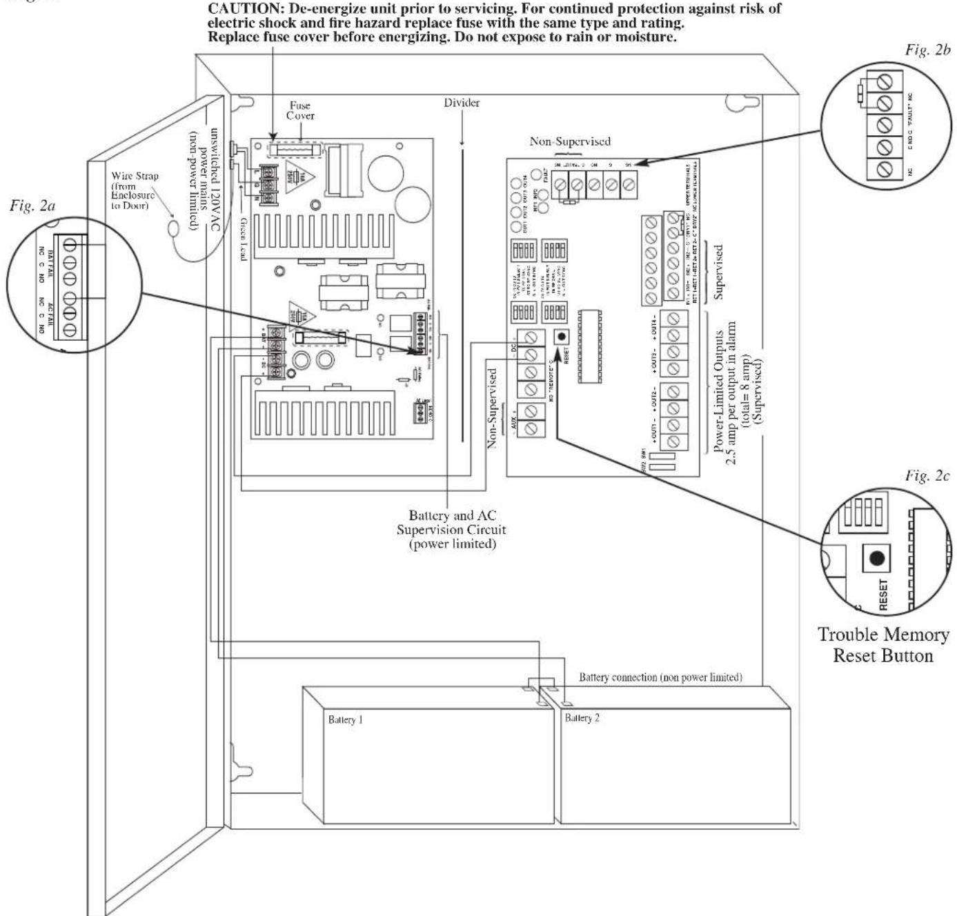
| C “FAULT” NC (Common trouble input) | An open circuit across this pair of terminals will cause [IN1 and IN2] to simultaneously signal a trouble condition back to the FACP (Typically used to report AC or BAT Fail). (form “C” contact 1 amp / 28VDC) (Fig. 2, pg. 7). |
| NC, C, NO (Common trouble input) | These are dry contact trouble outputs that follow any general loop/system trouble conditions. (Typically used to trigger a digital communicator or other reporting device). (form “C” contact 1 amp / 28VDC 0.35 Power Factor) (Fig. 2, pg. 7). |
| -AUX+ | This separate 1 amp max auxiliary Special Application Power output circuit is typically used to power 4-wire smoke detectors. See attached list of devices (Appendix A, pgs. 10-12). |
| + DC -- 24VDC from power supply. |
Note: Unit is equipped with 1 amp max. auxiliary output: “AUX” will remain battery backed up during power outage. For loads connected to “AUX” please, refer to battery “Stand-by Specifications” above for ratings. When loads are connected to “AUX” output during alarm condition, the remaining outputs may, not exceed 8 amp total alarm current (example:AUX = 1 amp, outputs up to 7 amp).
Terminal Identification Table: AL800ADA Power Supply Board*
| TerminalLegend | Function/Description |
| L, G, N | Connect 120 VAC to these terminals:L to hot, N to neutral, G to ground. |
| + DC - 24VDC @ 8 amp in alarm non-power limited output. | |
| AC FAILNC, C, NO | Form “C” dry contacts used to instantaneously signal the loss AC to local annunciation devices, with AC present terminals marked NO and C are open, NC and C are closed.When loss of AC occurs terminals marked NO and C are closed, NC and C are open. |
| AC LOCALNC, C, NO | Form “C” dry contacts used to instantaneously signal the loss AC to local annunciation devices, with AC present terminals marked NO and C are open, NC and C are closed.When loss of AC occurs terminals marked NO and C are closed, NC and C are open. |
| BAT FAILNC, C, NO | Form “C” dry contacts used to signal low battery voltage or loss of battery voltage.Under normal conditions terminals marked NO and C are open, NC and C are closed.During a trouble condition terminals marked NO and C are closed, and NC and C are open (Fig. 2, pg. 7). |
| + BAT - Stand-by battery input (leads provided) (Fig. 2, pg. 7). | |
\*Power Board Parameter Specifications:
- AC Fail condition will report approximately 30 seconds after loss of AC. To delay report for 2.5 to 3 hours cut jumper AC DELAY on the Power Supply Board (AC trouble output delay option). If this mode is selected the Power Supply Board must be reset by removing all power to it for 30 seconds.
- Low battery condition will report at approximately 21VDC.
- Battery presence detection will report with in 180 seconds after battery remains undetected (missing or removed). A restored battery will report within 30 seconds.
LED Diagnostics:
AL800ADA - Power Supply Board
| Red (DC) | Green (AC) | Power Supply Status |
| ON ON Normal operating condition. | ||
| ON OFF Loss of AC, Stand-by battery supplying power. | ||
| OFF ON No | DC output. | |
| OFF OFF Loss of AC. Discharged or no stand-by battery. No DC output. | ||
AL800LGK - Logic Board
| LED | OFF | ON | BLINK (LONG)* | BLINK (SHORT)** |
| ON | Normal | Alarm Condition | Trouble Condition | Trouble Condition Memory |
| ON | Normal | Alarm Condition | Trouble Condition | Trouble Condition Memory |
| OFF | Normal | Alarm Condition | Trouble Condition | Trouble Condition Memory |
| OFF | Normal | Alarm Condition | Trouble Condition | Trouble Condition Memory |
| Input 1 | Normal | Alarm Condition | Trouble Condition | - |
| Input 2 | Normal | Alarm Condition | Trouble Condition | - |
| Fault | Normal | Alarm Condition | - | - |
* Indicates current trouble condition. When trouble (open, short or ground) occurs on a specific output, the corresponding red output LED, [OUT1-OUT4] will blink. The corresponding green input LED will blink as well. Loop trouble will report within 30 seconds.
**Indicates trouble condition memory. When a trouble condition restores, the units red output LED, [OUT1-OUT4] will blink with a shorter and distinctly a different duration. The green input LEDs will be off (normal condition). To reset the memory depress the reset button (Fig. 2c, pg. 7). The LED(s) will extinguish.
Note: If indicating circuits have been restored, memory reset is not required for normal operation of the unit.
Optional Hookup Diagram:
Fig. 2
Optional hookups:
1- Battery and AC monitoring: AC or Battery Fail condition will cause the common trouble input [C “FAULT” NC] to report back to the FACP via input 1 and input 2. The common trouble input may also be used for other optional supervisory monitoring.
To report AC and Battery Trouble connect the battery and AC Fail relay output shown in (Fig. 2a) to the common trouble input.
2- Dry contact input (C "DRY1" NC) (C "DRY2" NC) can be used to alarm output from an addressable module (these inputs are unidirection and cannot report back to trigger module).
Connection to triggering devices must be made within 20ft of distance and using conduit for wiring.
3- Auxiliary output (-AUX+) 24VDC at 1 amp max.
4- AC Local [NC, C, NO] should connect to the host control panel for local annunciation of the trouble condition.
Note: If common trouble input, terminals marked [C “FAULT” NC] are not used, these terminals must be shorted (connect jumper) to remain inactive. For optional hookups (Fig. 2b).
Maintenance:
Unit should be tested at least once a year for the proper operation as follows:
Output Voltage Test: Under normal load conditions, the DC output voltage should be checked for proper voltage level (26.2-26.4VDC recommended range).
Battery Test: Under normal load conditions check that the battery is fully charged. Check specified voltage both at battery terminal and at the board terminals marked [+ BAT --] to insure there is no break in the battery connection wires.
Fuses: Check input and output fuses on the power supply board, replace if necessary. Input fuse rating is 8 amp @ 250V, Output fuse rating is 15 amp @ 32V
Note: Maximum charging current is 3.2 amp.
Note: Expected battery life is 5 years, however it is recommended changing batteries in 4 years or less if needed.
Battery Calculation Worksheet
| Device | Number of Devices | Current per Device | Stand-by Current | Alarm Current | ||
| For each device use this formula: This column x This column = Equals Current per number of devices. | ||||||
| AL802ULADAJ(Current draw from battery) | 1 | Stand-by: 90mA | 90mA | |||
| Alarm: | 175mA 175mA | A | ||||
| A | AL802 Current | 90mA 175mA | ||||
| Auxiliary Devices Refer to device manual for current ratings. | ||||||
| Alarm/Stand-by mA mA mA | ||||||
| Alarm/Stand-by mA mA mA | ||||||
| Alarm/Stand-by mA mA mA | ||||||
| B | Auxiliary Devices Current (must not exceed 1 amp) | |||||
| Refer to device manual for current ratings. | ||||||
| Alarm: | mA | 0mA | mA | |||
| Alarm: | mA | 0mA | mA | |||
| Alarm: | mA | 0mA | mA | |||
| Alarm: | mA | 0mA | mA | |||
| C | Notification Appliances Current must not exceed 8 amp (8000mA) 0mA | mA | ||||
| D | Total alarm current | mA mA | ||||
| E | Total current ratings converted to amperes (line D x .001) A A | |||||
| F | Number of standby hours (24 for NFPA 72, Chapter 1, 1-5.2.5). | H | ||||
| G | Multiply lines E and F. Total stand-by AH | AH | ||||
| H | Alarm sounding period in hours.(For example, 5 minutes = .0833 hours.) | H | ||||
| I | Multiply lines E and H. Total alarm AH | AH | ||||
| J | Add lines G and I. Total stand-by and alarm AH | AH | ||||
| K | Multiply line J by 1.30.(30% extra insurance to meet desired performance)Total ampere - hours required | AH | ||||
Units are capable of recharging 40 AH battery max. If total ampere - hour required exceeds 40 AH, decrease AUX current to provide enough stand-by time for the application.
A.1 Four (4) Wire Smoke Detectors
Table A-1 below lists four (4) wire smoke detectors compatible with AL802ULADAJ AUX output.
| Smoke Detector/Base | Detector Type | Max Standby Current (mA) | Alarm Current (mA) |
| System Sensor B112LP Base 0.12 36 | |||
| System Sensor B114LP Base * * | |||
| System Sensor B404B Base * * | |||
| System Sensor DH100ACDC Photoelectric 0.15 0.70 | |||
| System Sensor DH100ACDCLP Photoelectric 0.15 0.70 | |||
| System Sensor DH100ACDCLPW Photoelectric 0.15 0.70 | |||
| System Sensor DH400ACDCI Ionization Duct 25 95 | |||
| System Sensor DH400ACDCP | Photoelectric Duct | 25 | 95 |
| System Sensor 1112/24/D | Ionization | 0.05 | 50 |
| System Sensor 1424 | Ionization | 0.10 41 | |
| System Sensor 1451 (w/B402B Base) | Ionization | 0.10 | 39 |
| System Sensor 2112/24ATR | Photoelectric | 0.50 | 60/70 |
| System Sensor 2112/24AITR | Photoelectric | 0.50 | 60/70 |
| System Sensor 2112/24/D | Photoelectric 0.05 50 | ||
| System Sensor 2112/24R | Photoelectric | 0.50 | 60/70 |
| System Sensor 2112/24TR | Photoelectric | 0.50 | 60/70 |
| System Sensor 2112/24T/D | Photoelectric w/135° Thermal | 0.05 50 | |
| System Sensor 2112/24TSRB | Photoelectric w/135° Thermal Supervisory Relay | 15 | 45 |
| System Sensor 2312/24TB | Photoelectric 0.12 50 | ||
| System Sensor 2412 (12 volt) | Photoelectric 0.12 77 | ||
| System Sensor 2412AT (12 volt) | Photoelectric | 0.12 | 58 |
| System Sensor 2412TH (12 volt) | Photoelectric 0.12 77 | ||
| System Sensor 2424 | Photoelectric 0.10 41 | ||
| System Sensor 2424TH | Photoelectric 0.10 41 | ||
| System Sensor 2451 | Photoelectric 0.10 39 | ||
| System Sensor 2451TH (with/B402B Base) | Photoelectric 0.10 39 | ||
| System Sensor 2W-MOD | Loop Test/Maintenance Mod. | 30 | 50 |
| System Sensor 4W-B (12/24 volt) Photoelectric I | ^3 | .05 23 | |
| System Sensor 4WT-B (12/24 volt) Photoelectric I | ^3 w/Therm .05 | 23 | |
| System Sensor 4WTA-B (12/24 volt) I | ^3 Photo w/Therm/Sounder .05 | 35 | |
| System Sensor 4WTR-B (12/24 volt) I | ^3 Photo w/Therm/Relay .05 | 35 | |
| System Sensor 4WTR-B (12/24 volt) | I ^3 Photo w/Therm/ Sounder/Relay | .05 50 | |
| System Sensor 4WITAR-B (12/24 volt) | I ^3 Photo w/Isolated Therm/Sounder/Relay | .05 50 | |
| System Sensor 2W-MOD2 | I ^3 Loop Test/Maintenance Mod. | .05 * | |
| System Sensor RRS-MOD | I ^3 Reversing Relay/Sync Module | .05 * | |
| System Sensor 6424 Projected Beam 10 | 28.4 | ||
| System Sensor Beam 1224(S) | Projected Beam | 17 | 38.5 |
| * Contact manufacturer for current draws | |||
A.2 Relays
Table A-3 below lists relays compatible with AL802ULADAJ AUX output.
| Manufacturer | Model | Current (mA) |
| System Sensor | PR-1 | 15 |
| PR-2 | 30 | |
| PR-3 | 30 | |
| EOLR-1 | 30 | |
| R-10T | 23 | |
| R-14T | 23 | |
| R-20T | 40 | |
| R-24T | 40 | |
| R-10E | 23 | |
| R-14E | 23 | |
| R-20E | 40 | |
| R-24E | 40 |
Enclosure Dimensions:
18"H x 14.5"W x 4.5"D
Altronix is not responsible for any typographical errors.
140 58th Street, Brooklyn, New York 11220 USA, 718-567-8181, fax: 718-567-9056
web site: www.altronix.com, e-mail: info@altronix.com. Lifetime Warranty, Made in U.S.A.
IIAL802ULADAJ G26J

- Altronix®
- AL802ULADAJ - NAC Power Extender
- Overview:
- Specifications:
- Agency Listings:
- Input:
- Output:
- Battery Backup:
- Supervision:
- Visual Indicators:
- Special Features:
- Added Features:
- Enclosure Dimensions and Descriptions: AL802ULADAJ
- Product Weight:
- Installation Instructions:
- Class A, Style Z Class B, Style W, Y, SW1 & SW2 Settings:
- Output Programming Selection Table:
- \*Power Board Parameter Specifications:
- LED Diagnostics:
- Optional Hookup Diagram:
- Optional hookups:
- Maintenance:
- A.1 Four (4) Wire Smoke Detectors
- A.2 Relays
- Enclosure Dimensions:
Brand : Altronix
Model : AL802ULADAJ
Category : Inverter