VZ-PVM-Z4W3 - Surveillance ViewZ - Free user manual and instructions
Find the device manual for free VZ-PVM-Z4W3 ViewZ in PDF.

User questions about VZ-PVM-Z4W3 ViewZ
0 question about this device. Answer the ones you know or ask your own.
Ask a new question about this device
Download the instructions for your Surveillance in PDF format for free! Find your manual VZ-PVM-Z4W3 - ViewZ and take your electronic device back in hand. On this page are published all the documents necessary for the use of your device. VZ-PVM-Z4W3 by ViewZ.
USER MANUAL VZ-PVM-Z4W3 ViewZ
text_image
ViewZ® DRIVING VISUAL INNOVATIONViewZ®
www.viewzusa.com
Please read this manual thoroughly before use, and keep it handy for future reference.
CONTENTS
Safety Instruction 3
- Mark Indication & Substance 4
- Warning 4
- Caution 5
- Dot Defect (dead pixel) of TFT 5
- FCC RF INTERFERENCE STATEMENT 6
- WIRING (DC 24V) 7
Installation 8
- Package 8
- Interface 9
- Remote Control Function 10
Function 11
- Monitor Button Function 11
- OSD Control and Function 13
- CAMERA Control and Function 21
- Media Player Control and Function.... 32
Mounting Guide 39
Specification 40
Trouble Shooting 42
RMA 43
Warranty 44
SAFETY INSTRUCTION
Important Safety Instruction
- Read all warnings.
- Follow all instructions to ensure longevity of monitor.
- Do not place the monitor near water.
-
Clean only with dry cloth.
-
Do not block any ventilation openings. Install in accordance with the manufacturer's instructions.
-
Do not install near any heat sources such as radiators, heat registers, stoves, or other heat generating devices.
-
Do not override the safety purpose of the polarized or grounding-type plug.
-
A polarized plug has two blades with one wider than the other.
-
A grounding type plug has two blades and a third grounding prong.
-
The wide blade and the third prong are provided for your safety.
-
If the provided plug does not fit into your outlet, consult with electrician for replacement of the outlet.
-
Protect the power cord from being walked on or pinched particularly at plugs, convenience receptacles and the point where it connects to the monitor.
-
Only use attachment/accessories specified by the manufacturer.
-
Use only with the cart, stand, tripod, bracket or table specified by the manufacturer or sold with the monitor. When a cart is used, use caution when moving the cart & monitor in combination to avoid injuries.
-
Unplug the monitor during lightning storms or when unused for long periods of time.
-
Refer all servicing to qualified service personnel. Servicing is required when the monitor has been damaged in any way.
The monitor shall not be exposed to dripping or splashing and objects containing liquids, such as vases shall not be placed near the monitor.
The monitor should have ample distance (e.g. 10cm) from the wall for sufficient ventilation.

SAFETY INSTRUCTION
Important Safety Instruction
Mark Indication and Substance


CAUTION : TO REDUCE THE RISK OF ELECTRICAL SHOCK, DO NOT REMOVE COVER (OR BACK). NO USER SERVICEABLE PARTS INSIDE. REFER SERVICING TO QUALIFIED SERVICE PERSONNEL

This symbol is intended to alert the user to the presence of uninsulated & dangerous voltage within the monitor's enclosure that may be of sufficient magnitude to constitute a risk of electric shock to persons.

This symbol is intended to alert the user to the presence of important operating and maintenance (servicing) instructions in the literature accompanying the monitor.
Warning
- Do not use damaged or loose cables and plug.
- Do not pull the plug out by the wire nor touch the plug with wet hands.
- Use only a properly grounded plug and receptacle.
- Do not connect too many extension cords or plugs to one outlet.
- Do not excessively bend the plug and wire.
- Do not disconnect the power cord while it's still plugged into the monitor.
- Do not place any heavy objects on the power cord. Damage to the cord may cause shock or fire.
- Never open the monitor. There are no user-serviceable parts inside and opening will void warranty.
- Removing covers may expose you to dangerous shock hazards or other risks.
- Keep any heating devices away from the power cable and monitor.
- Do not place the monitor near water.
- Do not insert objects of any kind into the monitor's open slots, as they may touch dangerous voltage points.
- Please follow the laws and regulations of your municipality to dispose the monitor properly.
- Do not use the monitor in high temperature, humid, dusty or oily areas.
- Do not install the monitor where it will be exposed to continual vibration.
- Keep the plastic packaging out of children's reach.
• If any damage is detected upon first opening the box, contact agency from which you bought the monitor directly.
- If your monitor does not operate normally – in particular, if there is any unusual sound or smell coming from the monitor – unplug it immediately and contact an authorized dealer or the service center.
SAFETY INSTRUCTION
Important Safety Instruction

Caution
• If the connector between the plug and the pin is dusty or dirty, clean it properly using a dry cloth.
- Make sure to unplug the power cord before cleaning the monitor.
- Make sure to leave a gap between monitor and wall.
- Do not drop the monitor when moving it.
- Place your monitor in a location with low humidity and minimum dust.
• Install the monitor base on a showcase or shelf so that the end of the base does not protrude from the showcase or shelf.
- Do not place the monitor on an unstable or small surface area.
- Do not install inside a vehicle.
- Disconnect the plug from the outlet during storms or lightning or if it has not been used for a long time.
- Do not try to move the monitor by pulling on the power cord.
- Do not cover the vents on the monitor.
- When moving the monitor, turn off and unplug the power cord. Make sure that all cables, including HDMI cable and cables connected to other devices, are disconnected before moving it.
- Place the monitor out of children's reach, as they could damage it by hanging onto it.

Available Temperature & Humidity
• Operating Temperature : 32°F \~ 104°F / 0°C \~ 40°C
• Operating Humidity : 20 \~ 70% RH
Dot Defect (dead pixel) of TFT
ViewZ monitors are manufactured using high-end semiconductor technology with precision ratings of 99.9% and above. However, it may be the case that certain RGB and white pixels seem darker (or entirely unlit i.e. black).
Modern production methods cannot guarantee an absolute fault-free monitor. To this effect, no LED manufacturer can guarantee a defect free panel. A few isolated pixel or sub-pixel faults are considered tolerable and different policies exist that govern the amount of these tolerable values.
While most pixel faults occur in isolated regions, a cluster of dead pixels or sub-pixels can sometimes form for which a separate ruling applies. A cluster is defined as an area of 5x5 pixels. ViewZ's policy on pixel failure: either as an isolated fault or in the form of a cluster is outlined on the website: www.viewzusa.com
FCC RF INTERFERENCE STATEMENT
Note
This equipment has been tested and found to comply with the limits for a Class A digital device, pursuant to Part 15 of the FCC Rules. These limits are designed to provide reasonable protection against harmful interference in a residential installation.
This equipment generates, uses and can radiate radio frequency energy and, if not installed and used in accordance with the instructions, may cause harmful interference to radio communications. However, there is no guarantee that interference will not occur in a particular installation.
If this equipment does cause harmful interference to radio or television reception, which can be determined by turning the equipment off and on, the user is encouraged to try to correct the interference by one or more of the following measures.
- Reorient or relocate the receiving antenna.
- Increase the separation between the equipment and receiver.
- Connect the equipment into an outlet on a circuit different from that to which the receiver is connected.
- Consult the dealer or an experienced radio, TV technician for help.
- Only shielded interface cable should be used.
Finally, any changes or modifications to the equipment by the user not expressly approved by the grantee or manufacturer could void the users authority to operate such equipment.
▶ DOC COMPLIANCE NOTICE
This digital apparatus does not exceed the Class A limits for radio noise emissions from digital apparatus set out in the radio interference regulation of Canadian Department of communications.
WIRING (DC 24V input only)
- On the back of the monitor, loosen the thumb screws and lower the access panel.
- Attach the leads from the power supply (supplied) to the left and right connectors.

WARNING: Do not connect a ground to the center post. Please be careful of voltage polarity.
- When finished, secure the access panel. Table A shows the recommended maximum wiring distances (transformer to load), and are calculated with a 10-percent voltage drop.
VZ-DC24-320 (Power Transformer) Test ResultInput : Power So
23" HD-PVM-N - 3 MONITORS - VZ-PVM-Z2B3N & Z2W3N
| Cable Type - 18AWG (Current : 12~19 A) | 1 Set of HD-PVM-N | 2 Set of HD-PVM-N | 3 Set of HD-PVM-N | ||||||
| ft / meter | DC 24V | DC 27V | Max. V | DC 24V | DC 27V | Max. V | DC 24V | DC 27V | Max. V |
| 100 ft / 30.48 m | tested | tested | tested | tested | tested | tested | tested | tested | tested |
| 150 ft / 45.72 m | tested | tested | tested | tested | tested | tested | tested | tested | tested |
| 200 ft / 60.96 m | tested | tested | tested | tested | tested | tested | tested | tested | tested |
| 250 ft / 76.20 m | tested tested tested | tested | tested | tested | tested | tested | |||
| 300 ft / 91.44 m | tested tested tested tested tested | ||||||||
| 350 ft / 106.68 m | tested tested tested tested | ||||||||
27" HD-PVM-N - 3 MONITORS - VZ-PVM-Z3B3N & Z3W3N
| Cable Type - 18AWG (Current : 12~19 A) | 1 Set of HD-PVM-N | 2 Set of HD-PVM-N | 3 Set of HD-PVM-N | ||||||
| ft / meter | DC 24V | DC 27V | Max. V | DC 24V | DC 27V | Max. V | DC 24V | DC 27V | Max. V |
| 100 ft / 30.48 m | tested | tested | tested | tested | tested | tested | tested | tested | tested |
| 150 ft / 45.72 m | tested | tested | tested | tested | tested | tested | tested | tested | tested |
| 200 ft / 60.96 m | tested | tested | tested | tested | tested | tested | tested | tested | tested |
| 250 ft / 76.20 m | tested | tested | tested | tested | tested | tested | |||
| 300 ft / 91.44 m | Not Recommended | ||||||||
| 350 ft / 106.68 m | |||||||||
32" HD-PVM-N - 3 MONITORS - VZ-PVM-Z4B3N & Z4W3N
| Cable Type - 18AWG (Current : 12~19 A) | 1 Set of HD-PVM-N | 2 Set of HD-PVM-N | 3 Set of HD-PVM-N | ||||||
| ft / meter | DC 24V | DC 27V | Max. V | DC 24V | DC 27V | Max. V | DC 24V | DC 27V | Max. V |
| 100 ft / 30.48 m | tested | tested | tested | tested | tested | tested | tested | tested | tested |
| 150 ft / 45.72 m | tested | tested | tested | tested | tested | tested | tested | tested | tested |
| 200 ft / 60.96 m | tested | tested | tested | tested | tested | tested | |||
| 250 ft / 76.20 m | Not Recommended | ||||||||
| 300 ft / 91.44 m | |||||||||
| 350 ft / 106.68 m | |||||||||
INSTALLATION
Installation Tools
The following tools may be required depending on your installation.

text_image
Electronic Stud Finder Protective Eye-wearPencil Level Phillips ScrewdriverAssembly Components - provided
Your ViewZ monitor is shipped with all proper installation hardware and components. If there are parts missing and/or damaged, please stop the installation and contact ViewZ USA at (888)-998-4399.

text_image
ViewZPublic View Monitor (Qty 1) 110V Power Cable (Qty 1) DC24V Connector (Qty 1) User Manual (Qty 1)
natural_image
Black cable with two leads, no visible text or symbols

Remote Controller (Qty 1)
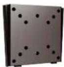
Mounting Option
Your ViewZ monitor is compatible with ViewZ monitor mounts. For more information, please contact ViewZ USA at (888)-998-4399.
Wall Mount
- Part #
WM05
- Flat Wall Mount
- Part #
WM11
- Tilting -45^ +45^
- Part #
AM02-A
- Tilting -20^ 20^
- VESA 50 \~ 100 23" PVM

- Swivel 180^ - VESA 75 \~ 100

- Swivel 180^ - VESA 75 \~ 200
23,27 & 32" PVM23 & 27" P'
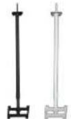
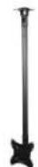
Ceiling Mount
- Part #
CM-6/18
- Tilting +15° - Rotation 360° - Black / White - Poll : 6 \~ 18 ft 23,27 & 32" PVM

CMKiT-02
- Tilting -12° \~ +5° - Rotation 360° - Poll : 35" \~ 70" 23,27 & 32" PVM
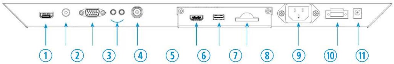
CONNECT EXTERNAL EQUIPMENTS
Interface Input Ports
The following image is the description of interface input ports
text_image
Diagram showing 11 labeled electronic device ports and connectors with directional arrows indicating connection points.- HDMI IN
- AV (BNC) IN
- VGA (15 Pin D-Sub) IN
- AUDIO IN / OUT
- CAMERA CVBS OUT
- (Optional) Media Player HDMI OUT
- (Optional) Media Player USB
- (Optional) Media Player SD Card
- AC 110V IN
- DC 24V IN
- DC 12V OUT
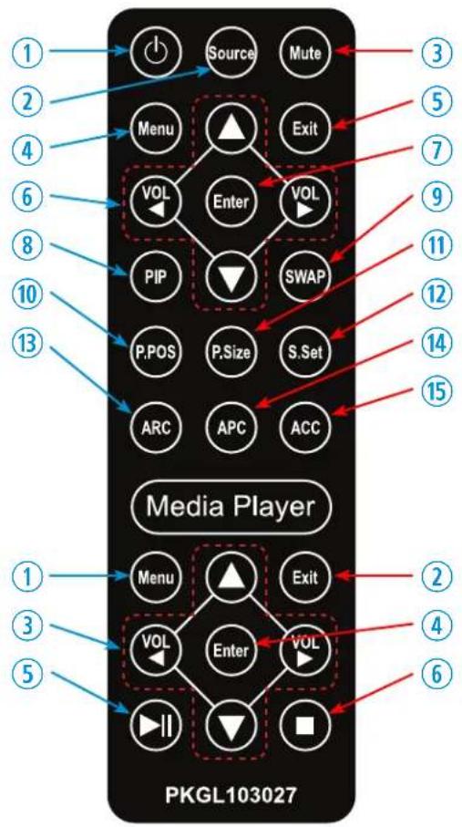
REMOTE FUNCTION
Remote Controller
Remote Controller
- Power
- Source - Select Input Source
- Mute - Turn off the sound
- Menu - Enter / Exit OSD
- Exit - Exit OSD with saving current value
- Left & Right ◀(VOL)▶, Up & Down ▲▼
- Enter - Select current setting value on Input source
- PIP - Launch the PIP (Picture In Picture) mode
- SWAP - Swap the main & sub on PIP
- P.POS - Change the sub picture position on PIP
- P.Size - Change the main & sub picture size on PIP
- S.Sat - Not working
- ARC - Aspect Ratio Control
- APC - Auto Picture Control
- ACC - Auto Color Control
text_image
1 2 3 4 5 6 7 8 9 10 11 12 13 15 Media Player PKGL103027 1 2 3 4 5 VOL Enter VOL Menu Exit VOL Enter SWAP P,POS P,Size S.Set ARC APC ACC Menu Exit VOL Enter VOLMedia Controller
- Menu - Enter / Exit Media Player Menu
- Exit - Exit Media Player Menu
- Left & Right ◀(VOL)▶, Up & Down ▲▼
- Enter - Confirm the selection
- Stop & Play - Freeze the media play
- Stop - Stop the media play
Display image, sound and custom settings can be adjusted in OSD (On Screen Display) menu by remote controller. To adjust monitor setting value :
- Press the 'MENU' button to enter the OSD menu
- Press the 'INPUT' button to select input source
- Press the ▲ / ▼ buttons to select the desired sub-menu. The selected submenu will be highlighted
- Press the 'ENTER' button to enter the sub-menu for adjusting items
- Change the value you wish to adjust by using the ◀ / ▶ buttons
- Press the 'MENU' button to confirm / exit for saving adjustment value on sub-menu
- Without entering OSD MENU, press ◀ / ▶ buttons to adjust the audio volume
- Press the 'MUTE' button to on / off audio - audio only works with VGA / AV input
CONTROL AND FUNCTION
On Monitor, Front Area

text_image
ViewZ DRIVING VIDEAL INNOVATION ① ② ③ ④- Built-in Camera / Motion Detection
The monitor will display the built-in camera's video Built-in camera has the motion detection function
- IR Sensor
Sensor for the remote controller
- LED Indicator
Green color: monitor on
Red color : monitor off
- Recording Indicator LED
User can choose a blinking LED color - red, blue, purple and no color.
CONTROL AND FUNCTION
On Monitor, Button Control
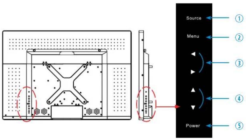
text_image
Source Menu Power ① ② ③ ④ ⑤- Source
To select an input source
- Menu
To enter or exit the OSD / Select a menu on OSD
- Left & Right ◀ (VOL) ▶
To change the value on the selected menu
- Up & Down ▲ ▼
To switch a menu on OSD
- Power
To turn the monitor power on / off
Monitor Button Function
All picture, sound settings and setup can be adjusted in OSD (On Screen Display) menu.
To adjust the OSD screen:
- Press the MENU button to enter the OSD MENU
- Press the ◀ / ▶ buttons to select the desired main-MENU. The selected main-MENU is highlighted
- Press the ▲ / ▼ buttons to select the desired sub-MENU. The selected sub-MENU is highlighted
- Change the value you wish to adjust by using the ◀ / ▶ buttons
- Press the MENU button to confirm the adjustment on sub-MENU
- Press the MENU button to exit the sub-MENU and go back to the main-MENU
- Press the MENU button to exit the OSD MENU
CONTROL AND FUNCTION
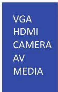
Select Input Source
VGA
HDMI
CAMERA
AV
MEDIA
Press 'SOURCE' button on monitor or 'INPUT' button on remote controller
Press ▲ / ▼ button to change input source and then press ◀ / ▶ button to select input source on monitor
Press ▲ / ▼ button to change input source and then press ◀ / ▶ button or Enter to select input source on remote controller
Volume
VOLUME
53
Press ◀ / ▶ buttons to adjust volume on monitor
Press ◀ / ▶ buttons to adjust volume on remote controller
Detect Source Signal Message
If you connect any input source, monitor will display current input source resolution and frequency.
CONTROL AND FUNCTION
Picture
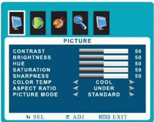
text_image
PICTURE CONTRAST 50 BRIGHTNESS 50 HUE 50 SATURATION 50 SHARPNESS 50 COLOR TEMP COOL ASPECT RATIO UNDER PICTURE MODE STANDARD SEL ADJ MENU EXIT▲/▼ MOVE ◀/▶ SELECT(ADJUST) MENU RETURN
| FUNCTION | VALUE | |
| CONTRAST | Adjust the contrast | 0 ~ 100 |
| BRIGHTNESS | Adjust the brightness | 0 ~ 100 |
| HUE ^1) | Adjust the hue | 0 ~ 100 |
| SATURATION | Adjust the color saturation | 0 ~ 100 |
| SHARPNESS | Adjust the sharpness | 0 ~ 100 |
| COLOR TEMP | Adjust the color setting | See table below |
| ASPECT RATIO | Adjust the video format | See table below |
| PICTURE MODE | Adjust the image color setting | See table below |
1) Only available in Composite (video) input
| PICTURE MODE | |
| MILD | Reduces contrast and sharpness |
| USER | Applies user selected values - brightness, contrast, color and hue |
| DYNAMIC | Provides enhanced contrast and sharpness |
| STANDARD | Provides standard contrast and sharpness |
| ASPECT RATIO | |
| 16 : 91)2)3) | Sets the image size to 16 : 9 |
| 4 : 31)2)3) | Sets the image size to 4 : 3 |
| UNDER2)3) | Adjusts the image size based on input resolution |
| ZOOM3) | Zooms the image size as factory preset zoom level |
1) VGA-input support
2) AV-input support
3) HDMI-input support
| COLOR TEMP. | |
| WARM | Give the white color a reddish tint |
| NORMAL | Give the white color a neutral tint |
| COOL | Give the white color a blue-ish tint |
COLOR TEMP.
CONTROL AND FUNCTION
Sound
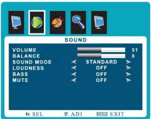
text_image
SOUND VOLUME 51 BALANCE 0 SOUND MODE STANDARD LOUDNESS OFF BASS OFF MUTE OFF SEL ADJ MENU EXIT▲/▼ MOVE ◀/▶ SELECT(ADJUST) MENU RETURN
FUNCTION VALUE
| VOLUME | Adjusts the volume | 0 ~ 100 |
| BALANCE Adjusts the balance 0 ~ 100 | ||
| SOUND MODE | Selects one of the presets | USER / MUSIC / MOVIE / STANDARD |
| LOUDNESS | Adjusts preset sound mode | MODE 1 / MODE 2/ MODE 3 / MODE 4 / OFF |
| BASS | Adjusts the bass level | ON /OFF / 1 - 12 |
| MUTE | Mutes the sound | ON / OFF |
CONTROL AND FUNCTION
System - OSD SETUP
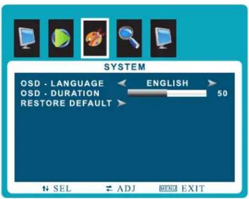
text_image
SYSTEM OSD - LANGUAGE OSD - DURATION RESTORE DEFAULT ENGLISH 50 SEL ADJ MENU EXIT▲/▼ MOVE ◀/▶ SELECT(ADJUST) MENU RETURN
| FUNCTION VALUE | ||
| OSD LANGUAGE | Sets the language of the OSD menu | English, Spanish, French Russian, Portuguese |
| OSD DURATION | Sets the OSD display time | 0 ~ 60 sec |
| RESTORE DEFAULT | Resets the monitor settings to the factory default | |
CONTROL AND FUNCTION
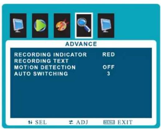
Advance - Adjust Recording Indicator Color / Recording Text

text_image
ADVANCE RECORDING INDICATOR RED RECORDING TEXT MOTION DETECTION OFF AUTO SWITCHING 3SEL # ADJ MENU EXIT
▲/▼ MOVE ◀/▶ SELECT(ADJUST) MENU RETURN
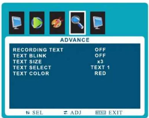
text_image
ADVANCE RECORDING TEXT OFF TEXT BLINK OFF TEXT SIZE x3 TEXT SELECT TEXT 1 TEXT COLOR RED SEL ADJ MENU EXITRECORDING TEXT Option Window
| FUNCTION | VALUE | |
| RECORDING INDICATOR | Sets the color of recording indicator LED | OFF / RED / BLUE / PURPLE |
| RECORDING TEXT | See table below | |
| MOTION DETECTION | See table on page 17 | |
| AUTO SWITCHING | See table on page 18 |
| FUNCTION | VALUE | |
| RECORDING TEXT | Enables the recording text | OFF / ON |
| TEXT BLINK | Sets the blinking text interval time | OFF / ON / 1~3 sec |
| TEXT SIZE | Adjusts the size of text | x 1/x 2/x 3 |
| TEXT SELECT ^1) | Selects the preset text | TEXT 1 / TEXT 2 / TEXT 3 |
| TEXT COLOR | Adjusts the color of text | RED / GREEN / BLUE / BLACK / WHITE |
1) PRESET TEXT - TEXT 1 : Recording / TEXT 2 : Recording in Progress / TEXT 3 : Surveillance in Progress
CONTROL AND FUNCTION
Advance - Adjust Motion Detection

text_image
ADVANCE RECORDING INDICATOR RED RECORDING TEXT MOTION DETECTION OFF AUTO SWITCHING 3SEL ↕ ADJ MENU EXIT
▲/▼ MOVE ◀/▶ SELECT(ADJUST) MENU RETURN

text_image
ADVANCE DETECTION ENABLE OFF DETECTION INPUT CAMERA DETECTION TIME 39 DETECTION TYPE FULLSEL ↕ ADJ MFND EXIT
MOTION DETECTION Option Window
| FUNCTION VALUE | ||
| DETECTION ENABLE | Enables the MOTION DETECTION function | OFF / ON |
| DETECTION INPUT | Selects the input source for Motion Detection | CAMERA / AV / MEDIA / VGA / HDMI |
| DETECTION TIME | Adjusts the time to display the swapped image / video which is triggered by motion detection. If user selects '10', the monitor will keep showing the swapped image/videos for 10 seconds whether or not motion detected. If there is no motion detection for 10 seconds, monitor will display original image/videos. | 3 ~ 100 sec |
| DISPLAY TYPE | Adjusts the display mode of motion detection. PIP : Displays the motion detection input as the PIP of the current video input source. This PIP is set by PIP main menu.* See the PIP in page 19FULL : Display the motion detection input as the full image/video on the monitor | PIP / FULL |
CONTROL AND FUNCTION
Advance - Adjust Auto Switching
text_image
ADVANCE RECORDING INDICATOR RED RECORDING TEXT MOTION DETECTION OFF AUTO SWITCHING 3SEL ↕ ADJ MENU EXIT
▲/▼ MOVE ◀/▶ SELECT(ADJUST) MENU RETURN
text_image
ADVANCE AUTO SWITCHING OFF TIME 10 VGA OFF HDMI OFF CAMERA ON AV ON MEDIA OFF SEL ADJ MENU EXITAUTO SWITCHING Option Window
| FUNCTION VALUE | ||
| AUTO SWITCHING | Enables the AUTO SWITCHING function | OFF / ON |
| TIME | Adjusts the time which the monitor displays one input source before switching to the other * Only selected two input sources can be displayed | 3 ~ 100 sec |
| VGA | Sets the VGA input source as the switching display source | OFF / ON |
| HDMI | Sets the HDMI input source as the switching display source | OFF / ON |
| CAMERA | Sets the CAMERA input source as the switching display source | OFF / ON |
| AV | Sets the AV input source as the switching display source | OFF / ON |
| MEDIA | Sets the MEDIA input source as the switching display source | OFF / ON |
CONTROL AND FUNCTION
PIP
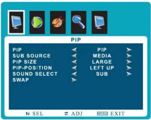
text_image
PIP PIP SUB SOURCE PIP SIZE PIP-POSITION SOUND SELECT SWAP PIP MEDIA LARGE LEFT UP SUB ↑ SEL ↕ ADJ MENU EXIT| FUNCTION | VALUE | |
| PIP | Selects PIP or OFF | See table below |
| SUB SOURCE | Selects PIP input source | See table below |
| PIP SIZE | Adjusts PIP window size | See table below |
| PIP-POSITION | Adjusts PIP position | See table below |
| SOUND SELECT | Selects sound source input | MAIN, SUB |
| SWAP | Swaps the main display |
▲/▼ MOVE ◀/▶ SELECT(ADJUST) MENU RETURN
| PIP | |
| OFF | PIP / PBP function off |
| PIP (Picture in Picture) | Separates the screen into two parts. One source device is displayed on the main screen at the same time the another source device is displayed in inset window |
| SUB SOURCE |
| PIP / PBP input source DVI, YPBPR, HDMI, VGA, AV1, AV2, AV3, AV4, AV5 |
| OFF |
| PIP SIZE | |
| SMALL, MEDIUM, LARGE | Display small, medium, large size PIP window on main display |
| PIP-POSITION | |
| LEFT UP / LEFT DOWN | Set the position of PIP window on main display |
| RIGHT UP / RIGHT DOWN | |
| PIP MODE | |||||
| HDMI | MEDIA (Optional) | VGA | AV | CAMERA | |
| HDMI | X | O | O | O | X |
| MEDIA (Optional) | O | X | O | O | O |
| VGA | O | O | X | O | O |
| AV | O | O | O | X | O |
| CAMERA | X | O | O | O | X |
CAMERA CONTROL & FUNCTION
Set up the menu
MAIN MENU
| 1. LENS | MANUAL |
| 2. EXPOSURE | ← |
| 3. BACKLIGHT | OFF |
| 4. WHITE BAL | ATW |
| 5. DAY & NIGHT | COLOR |
| 6. NR | ← |
| 7. SPECIAL | ← |
| 8. ADJUST | ← |
| 9. EXIT | SAVE & END |
Setting can be modified by using the OSD keypad (switch) located on the backside of camera.
- Press the button to access the MAIN MENU mode. The MAIN MENU is displayed on the monitor.
- Please select any function you wish to activate by using the UP/DOWN selection. The cursor can be moved up or down by using the UP/DOWN selection.
Set the cursor to point to the function which you want to operate. * MAIN MENU: Use UP/DOWN selection. | SUB MENU: Use LEFT/RIGHT selection.
-
Change the status of the selected feature using the LEFT/RIGHT selection. When the LEFT/RIGHT selection is done, available values and modes are displayed in order. Please keep the selection until you get to the mode you wish to operate.
-
When completed, move the cursor indicator to EXIT position and press the Button to finish the setting
Set up the menu - LENS
FUNCTION VALUE
| LENS | MANUAL / DC | |
| MANUAL | The level of brightness of a screen is automatically controlled using the Electronic Shutter, AGC and Sens-up | |
| DC (IRIS) | Select “INDOOR” and “OUTDOOR” mode.In “OUTDOOR” mode, choose one of modes;“MIN SHU” 1/30 & “MAX SHU” 1/2000. | |
| IRIS Speed | Select the brightness level of screen | 0 ~ 15 |
CAMERA CONTROL & FUNCTION
Set up the menu - EXPOSURE
| SHUTTER | AUTO | |
| AGC | 13← | |
| SENS-UP | OFF← | |
| BRIGHTNESS | 50← | |
| D-WDR | AUTO← | |
| DEFOG | AUTO← | |
| RETURN | RET← | |
EXPOSURE

natural_image
Man working at a desk with papers and books, no visible text or symbolsD-WDR Off

natural_image
Man working at a desk with books and papers, no visible text or symbolsD-WDR On
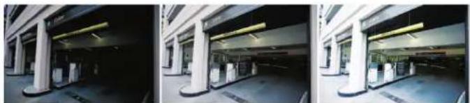
natural_image
Three-panel black-and-white photo sequence showing exterior view of a modern building with columns and parking areas (no visible text or signage)SENS-UP x2 SENS-UP x64 SENS-UP x128
| FUNCTION VALUE | ||
| SHUTTER | Adjust shutter speed. | AUTO & FLK level: 1/60 ~ 1/100000 / X2 ~ X60 |
| AGC(Auto Gain Control) | The higher the gain level, the brighter the screen. But the higher the noise. | 0 ~ 15 |
| SENS-UP | The Sens-up function allows the camera can display the bright image even extreme darkness.* On the AUTO selection : SENS-UP x2, x4, x6, x8, x10, x15, x20, x25, x30 | OFF / AUTO |
| BRIGHTNESS | Adjust the brightness level. | 1 ~ 100 |
| D-WDR | D-WDR(Digital-Wide Dynamic Range) block performs an image enhancement processing to Enhance visibility of an image by changing the brightness values to the level that people can Recognize the change.* On the 'ON' selection : select 0 ~ 8 | OFF / ON / AUTO |
| DEFOG | Brighten the image when it's foggy or cloudy. | OFF / AUTO |
| POS/SIZE | Select the region to apply DEFOG. | - |
| GRADATION | Set up the level of DEFOG. | 0 ~ 2 |
| DEFAULT | Go back to the factory setting of DEFOG. | - |
FUNCTION VALUE
CAMERA CONTROL & FUNCTION
Set up the menu - BACK LIGHT

text_image
MAIN MENU 1. LENS 2. EXPOSURE 3. BACKLIGHT 4. WHITE BAL 5. DAY & NIGHT 6. NR 7. SPECIAL 8. ADJUST 9. EXIT MANUAL BLC ATW COLOR SAVE & END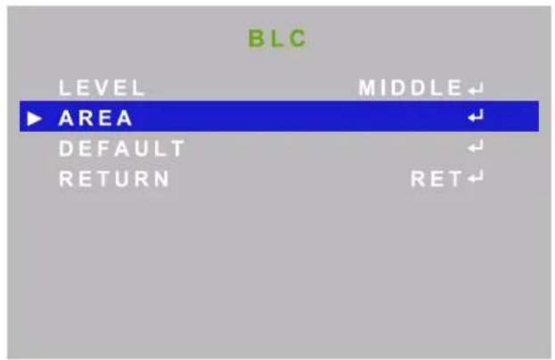
text_image
BLC LEVEL MIDDLE ▶ AREA DEFAULT RETURN RET| FUNCTION VALUE | ||
| BLC | Possible to select two areas at AREA SEL & can control GAIN, expand or reduce a length area by HEIGHT and the width area by WIDTH, Move to a width direction by LEFT/RIGHT and the length direction by TOP/BOTTOM. | |
| LEVEL | Set up the level of Black Mask. | LOW / MIDDLE / HIGH |
| AREA | Adjust the BLC area. | POSITION / SIZE / RET / AGAIN |
| DEFAULT | Go back to the factory setup of BLC. | - |
| RETURN | Go back to the top OSD menu. | - |

natural_image
Silhouette of a person standing in front of a window with high-rise buildings in the background (no visible text or symbols)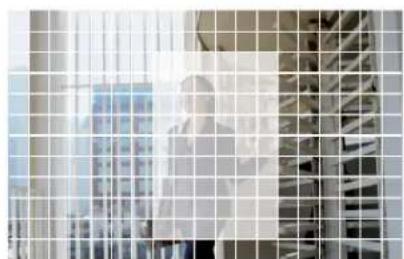
natural_image
Exterior view of a modern office building (no signage)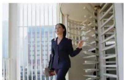
natural_image
Woman in business attire walking through a window with a spiral staircase and high-rise buildings in the background (no visible text or symbols)Original Image BLC ONBLC ON and Area Set Mode
CAMERA CONTROL & FUNCTION
Set up the menu - BACKLIGHT
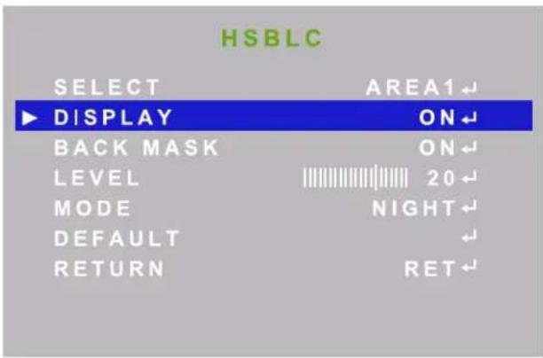
text_image
HSBLC SELECT AREA1 DISPLAY ON BACK MASK ON LEVEL 20 MODE NIGHT DEFAULT RETURN RET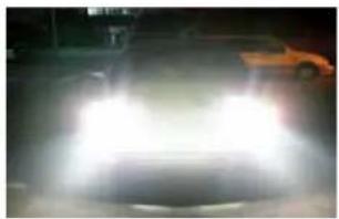
natural_image
Nighttime street scene with illuminated cars and headlights on a road (no visible text or symbols)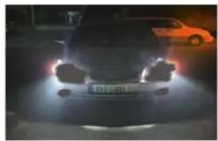
natural_image
Front view of a black car with headlights on, illuminated by a streetlamp, next to an orange car (no visible text or symbols)AfterBefore
| FUNCTION VALUE | ||
| HSBLC | It cuts off the strong lighting like the “headlight”. According to user's adjustment, zones & sensitivity can be adjustable. In case of the car surveillance, it remarkably performs recognizing License plate or subject HLC is a function to mask bright areas in order to prevent the target object from looking dark due to the backlighting. | |
| SELECT | Adjust the 4 HSBLC area. | AREA 1 ~ AREA 4 |
| BLACK MASK | Adjust the transmission range of light in HSBLC is show in Black. | OFF / ON |
| LEVEL | Set up the level of Black Mask. | 0 ~ 100 |
| MODE | Set up HSBLC mode for day and night. | NIGHT / ALL DAY (AGC LEVEL, 0 ~ 255) |
| DEFAULT | Go back to the factory setup of HSBLC. | - |
| RETURN | Go back to the top OSD menu. | - |
CAMERA CONTROL & FUNCTION
Set up the menu - WHITE BALANCE
MAIN MENU
- LENS MANUAL
- EXPOSURE
- BACKLIGHT OFF
| 4. WHITE BAL | ATW |
| 5. DAY & NIGHT | COLOR |
| 6. NR | ← |
| 7. SPECIAL | ← |
| 8. ADJUST | ← |
| 9. EXIT | SAVE & END |
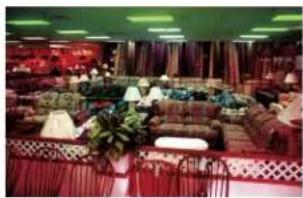
natural_image
Interior view of a modern restaurant with patterned seating and decorative lighting (no visible text or signage)
natural_image
Interior view of a large living room with sofa, coffee table, and decorative plants (no visible text or signage)
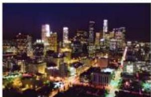
natural_image
Nighttime aerial view of a brightly lit city skyline with illuminated skyscrapers and streets (no visible text or signage)White Balance OnWhite Balanc
natural_image
Nighttime aerial view of a brightly lit city skyline with illuminated skyscrapers and streetlights (no visible text or signage)Good AWBBad AWB
| FUNCTION VALUE | ||
| MANUAL | Select this to fine-tune White Balance manually. Set White Balance first by using the ATW or AWC mode. After that switch to MANUAL mode, fine-tune the White Balance and then press the SET button. | BLUE (0 ~ 100) / RED (0 ~ 100) |
| AWC-SET | To find the optional setting for the current luminance environment in this mode, set the point the camera toward a sheet of white paper and press the SET button. If the environment changes, readjust it. | - |
| ATW | Select this when the color temperature is between 2300K & 9500K. | - |
| INDOOR | Select this when the color temperature is between 4500K & 8500K. | - |
| OUTDOOR | Select this when the color temperature is between 1800k & 10500k (sodium light inclusion). | - |
| AWB | Select this when the color temperature is between 2500K & 10500K. | - |
CAMERA CONTROL & FUNCTION
Set up the menu - DAY & NIGHT
MAIN MENU
| 1. LENS | MANUAL |
| 2. EXPOSURE | ← |
| 3. BACKLIGHT | OFF |
| 4. WHITE BAL | ATW |
| 5. DAY & NIGHT | COLOR |
| 6. NR | ← |
| 7. SPECIAL | ← |
| 8. ADJUST | ← |
| 9. EXIT | SAVE & END |
| B / W | |
| BURST | OFF |
| IR SMART | OFF |
| RETURN | RET← |
| FUNCTION VALUE | ||
| DAY & NIGHT | Useful in environments that restrict the use of artificial light. | |
| COLOR | Use to maintain color mode all the time. | - |
| B/W | Use to maintain B/W mode all the time. | - |
| BURST | Alters the color burst information passed to the video monitor. Since this is B/W mode, it doesn't effect color but can effect gain. If your monitor is showing a poor image and you are using long runs of cable, changing this setting from OFF to ON may improve the situation. | OFF / ON |
| IR SMART | Adjust the display saturation. | OFF / ON |
| RETURN | Go back to the top OSD menu. | - |
natural_image
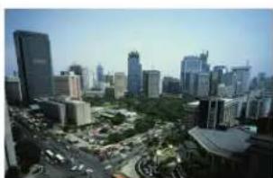
Cityscape with modern skyscrapers and green spaces, no visible text or signage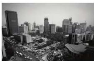
natural_image
Black-and-white aerial view of a modern city skyline with high-rise buildings and a busy urban area (no visible text or signage)
natural_image
Interior view of a storage room with shelves and a bright light source (no visible text or symbols)
natural_image
A person in a lab coat examining a device in a storage room with shelves of labeled items (no visible text or symbols)B / W SMART IR Off SMART IR OnColor
CAMERA CONTROL & FUNCTION
Set up the menu - DAY & NIGHT

text_image
D & N EXT D → N (DELAY) 3 ► N → D (DELAY) 3 RETURN RET ←
text_image
D & N AUTO D → N (AGC) 200 ► D → N (DELAY) 1 N → D (AGC) 80 N → D (DELAY) 1 RETURN RET ↙| FUNCTION VALUE | ||
| DAY & NIGHT | ||
| EXT | It is a mode to convert Day & Night by received external input signal. | - |
| D → N (DELAY) | Adjust the delay time which transmit from Day mode to Night mode. | 0 ~ 60 |
| N → D (DELAY) | Adjust the delay time which transmit from Night mode to Day mode. | 0 ~ 60 |
| AUTO | The camera will automatically show color image in high lux & black/white image in low lux. | - |
| D → N (AGC) | Adjust the sensibility of Auto Gain Control when turn between Day and Night mode. | 1 ~ 255 |
| D → N (DELAY) | Adjust the delay time which transmit from Day mode to Night mode. | 1 ~ 60 |
| N → D (AGC) | Adjust the sensibility of Auto Gain Control when turn between Day and Night mode. | 1 ~ 255 |
| N → D (DELAY) | Adjust the delay time which transmit from Night mode to Day mode. | 1 ~ 60 |
| RETURN | Go back to the top OSD menu. | - |
CAMERA CONTROL & FUNCTION
Set up the menu -NR
MAIN MENU
| FUNCTION VALUE | ||
| NR | Improve S/N ratio and more clean the low illumination quality and can be monitoring at night clearly without the image drag and noise phenomenon. | - |
| 2DNR | Adjust the 2DNR level.2DNR is to analyze individual frames of video, using special algorithm filter to mitigate the effects of noise. | OFF / LOW / MIDDLE / HIGH |
| 3DNR | Adjust the 3DNR level.3DNR level reduces more low light noise but it can cause ghost effect as well. | OFF / LOW / MIDDLE / HIGH |
| RETURN | Go back to the top OSD menu. | - |

natural_image
Interior view of a multi-level public space with people walking and conversing, featuring walkways and signage (no readable text or symbols)Original Image

natural_image
Interior view of a modern multi-level public space with people walking on elevated walkways (no visible text or signage)2D/3D NR
CAMERA CONTROL & FUNCTION
Set up the menu -SPECIAL

text_image
SPECIAL CAM TITLE ON ► D-EFFECT MOTION ON PRIVACY OFF LANGUAGE ENG DEFECT RS485 RETURN RET
natural_image
Street scene with pedestrians and a bus in the background (no visible text or signage)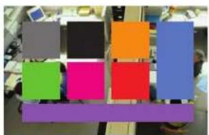
natural_image
Colorful abstract geometric shapes arranged in a grid, no text or symbols visible
natural_image
Street scene with pedestrians and a blue bus in the background (no visible text or symbols)Motion Detection OnOriginal Image
natural_image
Exterior view of a modern office building (no signage)4 Privacy Mask8 Privacy Mask
| FUNCTION VALUE | ||
| SPECIAL | ||
| CAM TITLE | Make a camera title. | - |
| D-EFFECT | FREEZE / MIRROR / NEG | |
| FREEZE | Freeze the current display picture. | |
| MIRROR | Reverse the picture vertically or horizontally or rotate the picture. | OFF / V-FLIP / MIRROR / ROTATE |
| NEG. IMAGE | Make the negative picture like film. | OFF / ON |
| MOTION | This feature allows you to integrate your cameras with external devices. | OFF / ON |
| SELECT | Select the region for motion | AREA 1 ~ 4 |
| DISPLAY | Show the motion detection area | OFF / ON (Position, Size, Again, Ret) |
| SENSITIVITY | Setup the sensitivity of motion detection | 0 ~ 100 |
| COLOR | Select color of Motion range in SELECT. | GREEN / RED / WHITE / BLUE |
| TRANS | Setup the level of Motion range in SELECT. | 1.0 / 0.75 / 0.25 / 0 |
| ALARM | Setup the Alarm | - |
| VIEW TYPE | Setup the Alarm view mode | OFF / ALL / OUTLINE / BLOCK |
| OSD VIEW | Setup the Alarm OSD view mode. | OFF / ON |
| ALARM | Turn on / off the Alarm. | OFF / ON |
| TIME | Setup the time of Alarm mode. | 0 ~ 15 |
| DEFAULT | Go back to the factory setting of motion. | - |
| PRIVACY | Set up the privacy mask area of camera. | OFF / ON |
| SELECT | Select the region for privacy. | AREA 1 ~ 8 |
| DISPLAY | Show the privacy area by selected option. | OFF / COLOR / MOSAIC / INV. |
| COLOR | Select color of Privacy range in SELECT. | WHITE/BLACK/CYAN/RED/BLUE/YELLOW/GREEN/USER |
| TRANS | Setup the level of Privacy range in SELECT. | 1.0 / 0.75 / 0.25 / 0 |
| DEFAULT | Go back to the factory setting of privacy | - |
CAMERA CONTROL & FUNCTION
Set up the menu -SPECIAL
DEFECT
| 1. LIVE DPC | ON← |
| 2. WHITE DPC | ON← |
| 3. BLACK DPC | OFF← |
| 4. RETURN | RET← |
RS485
| 1. CAM ID | 0 |
| 2. ID DISPLAY | OFF |
| 3. BAUDRATE | 2400 |
| 4. RETURN | RET← |
FUNCTION VALUE
| SPECIALLANGUAGE | Select the language of OSD | ENG / ARB / HEB / JRN / KOR / TUR / NEDPOR / RUS / POL / SPA / ITA / FRA / GER / CHR |
| DEFECT | Adjust the option of dead pixel correction | - |
| LIVE DPC | Auto dead pixel correction | OFF / ON |
| WHITE DPC | Adjust the dead pixel correction as white | OFF / ON |
| BLACK DPC | Adjust the dead pixel correction as black | OFF / ON |
| RS485 | Check your camera can support this feature.Set proper BAUD RATE to communicate with other devices. | - |
| CAM ID | You can select camera ID from 0 to 255when using remote control. | 0 ~ 255 |
| ID DISPLAY | Show the camera ID on the monitor. | OFF / ON |
| BAUDRATE | The baud rate is the rate at which information is transferred in a communication channel.in the serial port context, | 2400 ~ 38400 |
| RETURN | Go back to the top OSD menu. | - |
CAMERA CONTROL & FUNCTION
Set up the menu - ADJUST
MAIN MENU
| 1. LENS | MANUAL |
| 2. EXPOSURE | ← |
| 3. BACKLIGHT | OFF |
| 4. WHITE BAL | ATW |
| 5. DAY & NIGHT | COLOR |
| 6. NR | ← |
| 7. SPECIAL | ← |
| 8. ADJUST | ← |
| 9. EXIT | SAVE & END |
ADJUST
| 1. SHARPNESS | AUTO← |
| 2. MONITOR | LCD← |
| 3. LSC | ON |
| 4. VIDEO OUT | NTSC |
| 5. RETURN | RET← |
FUNCTION VALUE
| Adjust | Adjust the basic camera setup. - | |
| SHARPNESS | Adjust the sharpness. | OFF / AUTO |
| LEVEL | Adjust the sharpness level. | 0 ~ 100 |
| START AGC | Select the start point of AGC. | 1 ~ 255 |
| END AGC | Select the end point of AGC. | 1 ~ 255 |
| MONITOR | Select the prefer monitor type to adjust picture output. | LCD / CRT |
| LCD | Select the video output as LCD monitor | GAMMA 0.45 ~ USER / BLUE GAIN 0 ~ 100RED GAIN 0 ~ 100 |
| CRT | Select the video output as CRT monitor | BLACK LEVEL -30 ~ +30 / BLUE GAIN 0 ~ 100RED GAIN 0 ~ 100 |
| LSC | When using wide angle, you can compensate darkness of corner on the screen. | OFF / ON |
| VIDEO OUT | Select the video output | NTSC / PAL |
| RETURN | Go back to the top OSD menu. | - |
natural_image
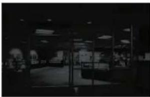
Interior view of a glass-walled building with visible windows and signage (no readable text or symbols)AGC OFF
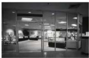
natural_image
Interior view of a modern retail store with glass doors and display areas (no visible text or signage)AGC ON
MEDIA PLAYER CONTROL
Remote Controller
Media Controller
- Source - To enter / exit Media player OSD, select the 'Media' on the input source list
- Menu - Enter / Exit Media player menu
- Exit - Exit Media player menu
- Left & Right ◀(VOL)▶, Up & Down ▲▼
- Enter - Confirm the selection
- Stop & Play - Freeze the media play
- Stop - Stop the media play
text_image
VGA HDMI CAMERA AV MEDIA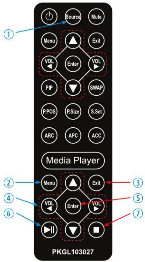
text_image
Source Mute Menu Exit VOL Enter VOL PIP SWAP P.POS P.Size S.Set ARC APC ACC Media Player PKGL103027 ① ② ③ ④ ⑤ ⑥ VOL Enter VOL ⑦* Input source list window will show on the top-left corner. Select 'MEDIA.'
Display image, sound, videos and custom settings can be adjusted in Media player OSD (On Screen Display) menu by remote controller. To adjust, play and stop media :
- When select 'MEDIA' among the input source list, press the 'MENU' button to enter the Media OSD
- Press the ◀ / ▶ buttons to select the desired sub-menu. The selected submenu will be highlighted
- Press the 'ENTER' button to enter the sub-menu for playing or adjusting setup
- Press the ◀ / ▶ / ▲ / ▼ buttons to select a file to play. Press 'ENTER' button to play selected content.
- Press the 'STOP' button to stop playing.
- Press the 'EXIT' button to exit to the Media OSD
- Press the 'SOURCE' button and select another input source to exit Media OSD
MEDIA PLAYER CONTROL
Media Card Interface

text_image
SD Card USB HDMI HDMI Out- HDMI OUT
Media player looping out
- Connect USB or SD card
- Connect USB or SD card devices to USB or SD Card slot located at the back of the PVM
- Remove USB or SD card
-
Return to the main menu and press exit
-
Remove the USB & SD card from the slot
Media Player OSD

text_image
File Manager Movies Photos Music Setup| FUNCTION | |
| File Manager | Displays all available video, photo and music files |
| Movies Plays video files from the SD Card or USB | |
| Photos | Displays image files from the SD Card or USB |
| Music | Plays music files from the SD Card or USB |
| Setup | Adjusts Audio, Video and System Effect |
MEDIA PLAYER CONTROL
File Manager
File Manager
Movies Photos

Music Setup


When you select File Manger on the entry menu of Media play:
- Press the ENTER button and then press ◀ / ▶ / ▲ / ▼ buttons to select a file to play or display.
- Press the ENTER button again to play the video file or display the image / slide-show.
- Press ■ button to stop playing the video file or displaying the image file / slide-show.
- Press ▶ || button to play or pause the video file.
- Press the EXIT button to return to the Media OSD MENU
Movies
File Manager
Movies Photos

Music Setup


When you select Moives on the entry menu of Media play:
- Press the ENTER button and then press ◀ / ▶ / ▲ / ▼ buttons to select a video file to play.
- Press the ENTER button again to play the video file.
- Press ■ button to stop the video file.
- Press ▶ || button to pause the video file.
- Press the EXIT button to return to the Media OSD MENU
MEDIA PLAYER CONTROL
Photos
File Manager
Movies Photos

Music Setup


natural_image
Green square icon with a white musical note symbol (no text or numbers)
natural_image
Green background with two white gear icons (no text or symbols)When you select Photos on the entry menu of Media play:
- Press the ENTER button and then press ◀ / ▶ / ▲ / ▼ buttons to select a image file to display.
- Press the ENTER button again to display the image or slide-show.
*Note: If you have more than one image file, the "slide-show" mode will activate automatically
- Press ■ button to stop displaying.
- Press ▶ || button to pause the slide-show and show only one image file in a non "slide-show" mode.
- Press the EXIT button to return to the Media OSD MENU
Music
File Manager
Movies Photos

Music Setup


natural_image
Green square icon with a white musical note symbol (no text or numbers)
natural_image
Green background with two white interlocking gears (no text or symbols)When you select Music on the entry menu of Media play:
- Press the ENTER button and then press ◀ / ▶ / ▲ / ▼ buttons to select a file to play.
- Press the ENTER button again to play the music file.
- Press ■ button to stop playing.
- Press ▶ || button to pause.
- Press the EXIT button to return to the Media OSD MENU
MEDIA PLAYER CONTROL
Setup
File Manager
Movies Photos

Music Setup


When you select Setup on the entry menu of Media play:
- Press the ENTER button and then press ◀ / ▶ buttons to select between Video / Audio / System setup.
- Select Video and then press ▲ / ▼ button to select the parameters which you want to adjust.
- Press the ENTER button again to select and adjust the details.
- Press the EXIT button to return to the Media OSD MENU
Setup - Video

Setup

text_image
Video System Audio Video Aspect Ratio 16:9 TV System 1080P 60Hz Scale Video Output to 90% Off 1080P 24Hz Off
Change category
Video
FUNCTION VALUE
| Aspect Ratio | Adjusts the video format of the images | Pan Scan 4:3 / Letter Box 4:3 / 16:9 / 16:10 |
| TV System Selects the video format 720p 50&60Hz / 1080i 50&60Hz | 1080P 50&60Hz / NTSC / PAL / 480P / 576P | |
| Scale Video Output to 90% | Sets up the scale of the video | Off / On |
| 1080P 24Hz | Selects the low frequency video | Off / On |
MEDIA PLAYER CONTROL
Setup - Audio

Setup

text_image
Audio Video System Audio Night Mode Off EQ Mode Default HDMI Output No Device Surround Sound AutoChange category Audio
When you select Setup on the entry menu of Media play:
- Press the ENTER button and then press ◀ / ▶ buttons to select between Video / Audio / System setup.
- Select Audio and then press ▲ / ▼ buttons to select the parameters to adjust.
- Press the ENTER button again to select and adjust the details.
- Press the EXIT button to return to the Media OSD MENU
| FUNCTION VALUE | ||
| Night Mode | Plays music at a lower volume | Off / On / Comfort |
| EQ Mode Selects different | EQ settings | Default / Pop / Live / Club / Rock / Bass / TrebleVocal / Powerful / Dance / Soft / Party / Classical |
| HDMI Output | Selects the output format of HDMI | HDMI LPCM, HDMI RAW, HDMI Auto |
| Surround Sound | Selects the surround mode | Auto / 5.1 CH / HD Audio |
MEDIA PLAYER CONTROL
Setup - System

Setup

text_image
System Audio Video System Language English Text Encoding Auto Auto Play Movies Factory Default Version Info USB UpgradeChange category
System
When you select Setup on the entry menu of Media play:
- Press the ENTER button and then press ◀ / ▶ buttons to select the Video / Audio / System setup.
- Select System and then press ▲ / ▼ button to select the parameters to adjust.
- Press the ENTER button again to select and adjust the details.
- Press the EXIT button to return to the Media OSD MENU
| FUNCTION VALUE | ||
| Language | Selects the language of the OSD menu | English / Chinese / Japanese / EspanolFrench / Deutsch / Italian / KoreanGreek / Portuguese |
| Text Encoding Selects the | language of encoding the text | Unicode(UTF8) / Western / Central EuropeanGreek / Cyrillic / Turkish / SE EuropeanJapanese (S-JIS) / Korean (EUC-KR) / Chinese |
| Auto Play | Selects an auto play file-type | Off / Movies / Photos / Music |
| Factory Default | Returns all settings back to factory default | Yes / No |
| Version Info | Shows the current media card version info | VER: Media Box 3.60.000091U |
| USB Upgrade | Selects USB to upgrade the firmware | Yes / No |
MOUNTING GUIDE
Wall Mounting (Optional)
VZ-PVM monitors are suitable for VESA wall mount (not included).

text_image
suitable for VESA wall mount (not included).M4 x L10 screws for VZ-PVM-Z2B3N / Z2W3N (23" - 100x100)
M4 x L10 screws for VZ-PVM-Z3B3N / Z3W3N (27" - 100x100)
M6 x L8 screws for VZ-PVM-Z2B3N / Z2W3N (23" - 200x200)
VZ-PVM-Z3B3N / Z3W3N (23" - 200x200)
VZ-PVM-Z4B3N / Z4W3N (32" - 200x200)
- VZ-PVM-Z2B3N/Z2W3N : VESA WALL MOUNT 100mm x 100mm, 200mm x 200mm
- VZ-PVM-Z3B3N/Z3W3N : VESA WALL MOUNT 100mm x 100mm, 200mm x 200mm
- VZ-PVM-Z4B3N/Z4W3N : VESA WALL MOUNT 200mm x 200mm
Attention!
VZ-PVM-Z2B3N/Z2W3N (100x100): You must use 4 * M4 x L10 screws to assemble this monitor and the wall mount bracket.
VZ-PVM-Z3B3N/Z3W3N (100x100): You must use 4 * M4 x L10 screws to assemble this monitor and the wall mount bracket.
VZ-PVM-Z2B3N/Z2W3N(200x200), VZ-PVM-Z3B3N/Z3W3N (200x200), VZ-PVM-Z4B3N/Z4W3N (200x200):
You must use 4 * M6 x L8 screws to assemble this monitor and the wall mount bracket.
! WARNING!
If user uses screws longer than
M4 x L10 mm for 100 x 100 - VZ-PVM-Z2B3N/Z2W3N, VZ-PVM-Z3B3N/Z3W3N
M6 x L8 mm for 200 x 200 - VZ-PVM-Z2B3N/Z2W3N, VZ-PVM-Z3B3N/Z3W3N, VZ-PVM-Z4B3N/Z4W3N
it may cause damage to the unit. Please use bolt of correct size and length as instructed.
! Mounting Safety !
At least two people are recommended to safely install the mount.
SPECIFICATION
| Model No. VZ-PVM-Z2B3N/Z2W3N VZ-PVM-Z3B3N/Z3W3N VZ-PVM-Z4B3N/Z4W3N | ||||
| Size & Type 23.6" | 27" | 32" | ||
| LCD | Panel Type | 23.6" LED Backlit Monitor | 27" LED Backlit Monitor | 32" LED Backlit Monitor |
| Pixel Pitch | 0.2715 (H) x 0.2715 (V) mm | 0.31125 (H) x 0.31125 (V) mm | 0.36375 (H) x 0.36375 (V) mm | |
| Brightness | 250 cd/m2 | 300 cd/m2 | 300 cd/m2 | |
| Contrast Ratio | 3000 : 1(Typ.) | 3000 : 1(Typ.) | 1200 : 1(Typ.) | |
| Viewing Angle | R/L : 89°/ 89° U/D : 89°/ 89° | |||
| Display Color | 16.7 Million Colors | |||
| Response Time | < 20 ms | < 12 ms | < 8 ms | |
| Resolution | 1920 (H) x 1080 (V) | |||
| Active Display Area | 521.28(H) x 293.22(V) mm | 597.9 (H) x 336.3 (V) mm | 698.4 (H) x 392.85 (V) mm | |
| Aspect Ratio | 16 : 9 | |||
| Case Type | Metal | |||
| Color Temperature | Warm / Normal / Cool | |||
| Speaker | 2 x 5W | |||
| Operating Temperature | 32°F ~ 104°F / 0°C ~ 40°C | |||
| Operating Humidity | 20 ~ 70% RH | |||
| Weight | Net : 22.04 lb / 10.0 kgGross : 29.76 lb / 13.5 kg | Net : 28.66 lb / 13.0 kgGross : 33.06 lb / 15.0 kg | Net : 33.06 lb / 15.0 kgGross : 39.68 lb / 18.0 kg | |
| INTERFACE | COMPOSITE VIDEO, HDMI (High Definition Multimedia Interface), VGA (RGB-PC)CAMERA OUT (CVBS), Audio In / Out | |||
| Safety & EMC Certification | CE / FCC / UL / ROHS | |||
| Electrical Ratings | AC IN | AC 110-240V, 50/60Hz | ||
| DC 24V IN | 24V === 2.0A | 24V === 3.0A | 24V === 4.0A | |
| Power Consumption | ≤ 36 W | ≤ 46 W | ≤ 50 W | |
| Accessories | HDMI cable, Power Supply & Cable, User's Manual, Remote controller | |||
SPECIFICATION
Camera Specification
| Parameters Description | ||
| Production Information | Product Name | 2MP HD Camera Module |
| Main Chipset | Sensor | 1/2.8 CMOS MN34227 |
| Lens | Lens Type | Vari-Focal / F1.3 Fixed Iris with ICR |
| Focal Length of the Lens | 2.7 ~ 12mm | |
| Camera | Resolution | 1920 (W) x 1080(H) @30HzCVBS (960H) / 1.0 Vp-p Composite (75Ω) |
| Video System | NTSC / PAL | |
| Minimum illumination | Color: 0.01Lux / B&W: 0.5Lux / Color: DSS:0.017 Lux / BW DSS:0.0008 Lux | |
| Day & Night Mode | External switch AUTO / Color / Black & White mode (OSD) | |
| Electronic Shutter Speed (AES) | AUTO | 1/50 (1/60) sec to 1/100,000 sec | |
| Auto Gain Control (AGC) | Support | |
| White Balance (AWB) | Support | |
| Digital Wide Dynamic Range | Support | |
| BLC / HSBLC | Support | |
| Motion | Support (4 Areas) | |
| Privacy Mask | Support (8 Areas) | |
| Signal to Noise (S/N) | ≥ 80 dB | |
| 2D/3DNR | Support (Low / Middle / High) | |
| External interface | CVBS Output (960H) | Support |
| Reset Button | Support | |
TROUBLESHOOTING GUIDE
- Check the following before calling for service.
- If the same problems continue after checking, contact the reseller you purchased the monitor from.
| At start | We recommend that you test with different input sources when you have trouble with the current input source. If symptom persists, follow the instructions below. After following the instructions below, please contact us at 1-888-99-VIEWZ. |
| No image or Noise on the screen | - Make sure the power cable is correctly plugged into the outlet- Make sure the power cable is correctly plugged into the monitor- Make sure the cable is correctly connected between monitor & source- Check brightness and see if brightness is set to '∅' - Check video source |
| Incorrect display or Half display | - Check your video source- Reset video source : connection, cable replacement, setting & more |
| Flickering and shadow image | - Check your input source setting for resolution and phase (Hz) |
| The audio function is not working | - Check the volume and make sure MUTE is not on- Check HDMI / Audio port cable connection |
| LED is flickering or no image | - Check the interface cable connection and make sure it's plugged in correctly- Check the input source |
TERMS OF WARRANTY / RMA
- The warranty period for this monitor is 3 years. The warranty will be voided for the scenarios listed below.
- You can also download the manual and information at VIEWZ web site: VIEWZUSA.COM
| Cases of Non-Warranty Coverage | When power feed to the monitor exceeds capacity and causes damage |
| Accident, Abuse, Misuse, Neglect, Fire, Water/liquids, Lightning or any act of nature | |
| Damaged by dropping, throwing and hitting the monitor | |
| Failure caused by users attempt to modify the product | |
| Failure by limited life of parts such as LED Lamps and any other consumables | |
| Damaged by using third party power cable, unstable power input and electric shock |
* Above information can be changed without notification - please check our website or contact ViewZ representative for latest RMA service policy.
* When shipping the monitor for RMA, make sure to pack safely to ensure the monitor is not damaged during shipping.
WARRANTY
ViewZ USA LIMITED 3 YEAR WARRANTY
What and Who is Covered by this Limited Warranty and for How Long
ViewZ USA warrants this product to be free from defects in material and workmanship for 3 years to the original owner of this product. The limited warranty is valid only for the original purchaser of the product.
What ViewZ USA Will Do
At the sole discretion of ViewZ USA, ViewZ USA will repair or replace any product or product part that is defective. If ViewZ USA chooses to replace a defective product or part, a replacement product or part will be shipped to you at no charge, but you must pay any labor costs.
What is Not Covered; Limitations
ViewZ USA disclaims any liability for damage to mounts, adapters, displays, projectors, other property, or personal injury resulting, in whole or in part, from improper installation, modification, use or misuse of its products.
ViewZ USA disclaims all other warranties, express or implied, including warranties of merchantability and fitness for a particular purpose. ViewZ USA is not responsible for incidental or consequential damages, including but not limited to, inability to use its products or labor costs for removing and replacing defective products or parts. Some states do not allow the exclusion or limitation of incidental or consequential damage, so the above limitation or exclusion many not apply to you.
What Customers Must Do for Limited Warranty Service
If you discover a problem that you think may be covered by the warranty you MUST REPORT it in writing to the address below within thirty (30) days. Proof of purchase (an original sales receipt) from the original consumer purchaser must accompany all warranty claims. Warranty claims must also include a description of the problem, the purchaser's name, address, and telephone number. General inquiries can be addressed to ViewZ USA Customer Service at 1-888-998-4399. Warranty claims will not be accepted over the phone or by fax.
ViewZ USA
Attn: Warranty Claim
177 W. Orangethorpe Ave.
Placentia, CA 92870
How State Law Applies
This warranty gives you specific legal rights, and you may also have other rights which vary from state to state.
Disclaimer
ViewZ USA intends to make this manual accurate and complete. However, ViewZ USA makes no claim that the information contained herein covers all details, conditions or variations, nor does it provide for every possible contingency in connection with the installation or use of this monitor. The information contained in this document is subject to change without notice or obligation of any kind. ViewZ USA makes no representation of warranty, expressed or implied, regarding the information contained herein. ViewZ USA assumes no responsibility for accuracy, completeness or sufficiency of the information contained in this document.
Contact Us
NORTH AMERICA
177 W. Orangethorpe Ave.
Placentia, CA 92870
USA and Canada
Phone: 1-888-998-4399
Fax: 1-714-996-1138
Other Locations
Phone: (001) 888-998-4399
Fax: (001) 714-996-1138