
Fusion FCASFP - Unspecified Chief - Free user manual and instructions
Find the device manual for free Fusion FCASFP Chief in PDF.


| Product Type | Menu Board Interface Kit (Mounting Accessory) |
| Weight Capacity | 75 lbs (34.0 kg) |
| Tilt Range | 0° to 20°, lockable at 0°, 10°, 20° |
| Mounting Rail Compatibility | Fusion series mounting rail (FMSECAP end caps required) |
| Included Brackets | Left and right interface brackets with latch mechanism |
| Hardware Included | M4, M5, M6, M8 screws; universal washers; spacers; locking hardware |
| Display Compatibility | VESA patterns up to 400x400 mm (based on screw selection) |
| Security | Optional padlock (not included) to lock display to rail |
| Installation Requirements | Phillips screwdriver, open-ended wrench; structural support must hold 5x total weight |
| Material | Steel brackets, zinc-plated hardware |
| Dimensions | Not specified; typical interface bracket height approx. 8.5 in (216 mm) |
| Weight (Kit) | Approx. 2.5 lbs (1.1 kg) |
| Warranty | Limited lifetime warranty by Milestone AV Technologies |
| Care and Maintenance | Wipe clean with soft, dry cloth; do not use abrasive cleaners |
| Repairability | Not user-serviceable; spare hardware parts available from Chief |
Frequently Asked Questions - Fusion FCASFP Chief
User questions about Fusion FCASFP Chief
0 question about this device. Answer the ones you know or ask your own.
Ask a new question about this device
Download the instructions for your Unspecified in PDF format for free! Find your manual Fusion FCASFP - Chief and take your electronic device back in hand. On this page are published all the documents necessary for the use of your device. Fusion FCASFP by Chief.
USER MANUAL Fusion FCASFP Chief
INSTALLATION INSTRUCTIONS

Menu Board Interface Kits
DISCLAIMER
Milestone AV Technologies and its affiliated corporations and subsidiaries (collectively "Milestone"), intend to make this manual accurate and complete. However, Milestone makes no claim that the information contained herein covers all details, conditions or variations, nor does it provide for every possible contingency in connection with the installation or use of this product. The information contained in this document is subject to change without notice or obligation of any kind. Milestone makes no representation of warranty, expressed or implied, regarding the information contained herein. Milestone assumes no responsibility for accuracy, completeness or sufficiency of the information contained in this document.
Chief® is a registered trademark of Milestone AV Technologies. All rights reserved.
DEFINITIONS
MOUNTING SYSTEM: A MOUNTING SYSTEM is the primary Chief product to which an accessory and/or component is attached.
ACCESSORY: AN ACCESSORY is the secondary Chief product which is attached to a primary Chief product, and may have a component attached or setting on it.
COMPONENT: A COMPONENT is an audiovisual item designed to be attached or resting on an accessory or mounting system such as a video camera, CPU, screen, display, projector, etc.

WARNING: A WARNING alerts you to the possibility of serious injury or death if you do not follow the instructions.

CAUTION: A CAUTION alerts you to the possibility of damage or destruction of equipment if you do not follow the corresponding instructions.

IMPORTANT SAFETY INSTRUCTIONS

WARNING: Failure to read, thoroughly understand, and follow all instructions can result in serious personal injury, damage to equipment, or voiding of factory warranty! It is the installer's responsibility to make sure all parts are properly assembled and installed using the instructions provided.

WARNING: Failure to provide adequate structural strength for this accessory can result in serious personal injury or damage to equipment! It is the installer's responsibility to make sure the structure to which the mounting system is attached can support five times the combined weight of all equipment.

WARNING: Exceeding the weight capacity can result in serious personal injury or damage to equipment! It is the installer's responsibility to make sure the combined weight of all components located on the accessory does not exceed the weight capacity listed in Table 1.
Table 1: Weight Capacity
| Maximum Weight Allowed | |
| FCASFP | 75 lbs (34.0 kg) |
| FMSIML | 125 lbs (56.7 kg) |
| FMSITL | 125 lbs (56.7 kg) |

WARNING: Use this accessory only for its intended use as described in these instructions. Do not use attachments not recommended by the manufacturer.

WARNING: Never operate this accessory if it is damaged. Return the accessory to a service center for examination and repair.

WARNING: Do not use this product outdoors.
--SAVE THESE INSTRUCTIONS--
TABLE OF CONTENTS
FCASFP....3
FMSIML....7
FMSITL....11
DIMENSIONS
![FCASFP 0.34 [8.7] 0.49 TYP. [12.5] 2.10 [53.4] 1.93 [49.0] 1.49 [37.9] 20° LOCKOUTS AT 0° 10° 20° 10.18 [258.6] PADLOCK HOLE DIMENSIONS: INCHES [MILLIMETERS]](/content/2026/06/1202730/images/ec97f344749bee8c40d9b87a53f9f96a0736a9be8416ad8c61cef7e1000e7d7b.jpg)
LEGEND
| Tighten Fastener | Phillips Screwdriver | ||
| Apretar elemento de fijación | Destornillador Phillips | ||
| Befestigungsteil festziehen | Kreuzschlitzschraubendreher | ||
| Apertar fixador | Chave de fendas Phillips | ||
| Serrare il fissaggio | Cacciavite a stella | ||
| Bevestiging vastdraaien | Kruiskopschroevendraaier | ||
| Serrez les fixations | Tournevis à pointe cruciforme | ||
| Loosen Fastener | Open-Ended Wrench | ||
| Aflojar elemento de fijación | Llave de boca | ||
| Befestigungsteil lösen | Gabelschlüssel | ||
| Desapertar fixador | Chave de bocas | ||
| Allentare il fissaggio | Chiave a punte aperte | ||
| Bevestiging losdraaien | Steeksleutel | ||
| Desserrez les fixations | Clé à fourche |
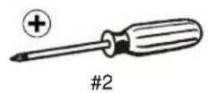
TOOLS REQUIRED FOR INSTALLATION - FCASFP


PARTS - FCASFP

DISPLAY ATTACH HARDWARE BAG
(Letters correspond to letters on bag)

A (4)
M4×12mm

D (4)
M5x12mm

B (4)
M4x20mm

E (4)
M5x20mm

C (4)
M4x25mm

F (4)
M5x25mm

G (4)
M6x12mm

J (4)
M8x12mm

H (4)
M6x20mm

K(4)
M8x20mm
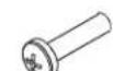
I(4)
M6x25mm

L(4)
M8x30mm

MA (4)
.750 × .323 × .250

MB (4)
.750 × .344 × .500

N (4)
[Universal washer]
Locking Hardware Kit

P (2)
10-24×5/8"

Q (2)
10-24

- 2017年1月1日
[Left interface bracket]
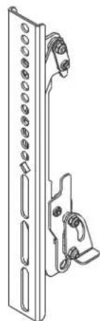
S (1)
[Right interface bracket]
INSTALL INTERFACE BRACKETS TO DISPLAYS
- Raise the latch mechanism on both interface brackets (R and S) to the OPEN position. (See Figure 1)

Figure 1
- Place displays face down on a soft, non-abrasive surface.

WARNING: IMPROPER INSTALLATION CAN LEAD TO DISPLAY FALLING CAUSING SERIOUS PERSONAL INJURY OR DAMAGE TO EQUIPMENT! Using screws of improper size may damage your display. Properly sized screws will easily and completely thread into display mounting holes. If spacers are required, be sure to use longer screws of the same diameter.
-
Select screw diameter by examining hardware (A-L) and comparing with mounting holes on display. (See Figure 2)
-
Select spacers:
-
Spacers are NOT required if mounting holes are not recessed and interface brackets (R and S) can lay flat against display.
-
Spacers (MA or MB) ARE required if mounting holes are recessed, or if protrusions prevent interface brackets (R and S) from laying flat.
-
Select screw length: (See Figure 2)
- By hand, insert SHORTEST length screw of selected diameter (A, D, G or J) through universal washer (N - if required), bracket (R or S), selected spacer (MA or MB-if required), into display mounting hole. Do NOT thread screw into hole at this time.
IMPORTANT ! : The M8 screws do NOT require a washer. Use the universal washer (N) ONLY with M4, M5 and M6 screws.
- Proper screw length requires base of screw head to protrude above flat washer a distance equal to or greater than the screw diameter. If screw length is inadequate, select longer screw. Select shortest screw which will protrude the required distance.
- Align the center of the interface brackets (R and S) with center of screen. (See Figure 2)
NOTE: The diamond-shape hole in the bracket corresponds to the center of the mount. - Use selected screws (A-L), universal washers (N-if required) and spacers (MA or MB-if required), to connect interface brackets (R and S) to back of display. (See Figure 2)
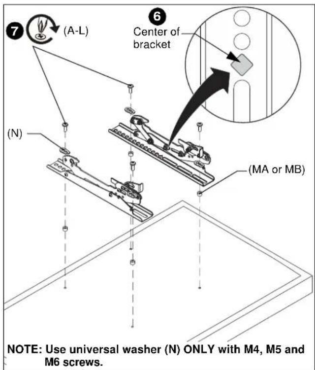
Figure 2
ATTACH DISPLAYS TO MOUNTING RAIL

WARNING: IMPROPER INSTALLATION CAN LEAD TO DISPLAY FALLING CAUSING SERIOUS PERSONAL INJURY OR DAMAGE TO EQUIPMENT! The displays must be located approximately evenly across the length of the rail.
- Ensure that the latch mechanisms on interface brackets (R and S) are already raised to the OPEN position. (See Figure 1)

CAUTION: BEFORE adding displays to the mounting rails, ensure end caps (FMSECAP) are in place at BOTH ends of mounting rail following instructions included with the FMSECAP.
- While supporting both sides of display, lower display onto mounting rail, hooking top of interface brackets onto top of mounting rail. (See Figure 3)
- Lower the latch mechanism on both interface brackets to lock bracket in place. (See Figure 3)

Figure 3
- Repeat for remaining interface bracket.
Interface Bracket Adjustment

CAUTION: ALWAYS keep a small distance between screens when making adjustments! Damage to screens possible if placed too close together.
Tilt
The interface brackets allow 0° to 20° tilt, and can be locked at 0° , 10° and 20° tilt.
-
If necessary, loosen button head tilt friction bolt (located on side of interface bracket). (See Figure 4)
-
Adjust tilt as required. (See Figure 4)
- The tilt may be locked at 0°, 10° and 20° using one 10-24 x 5/8" Phillips head screw (P) and one 10-24 lock nut (Q) per interface bracket. (See Figure 4)
- Tighten tilt friction bolt as necessary.
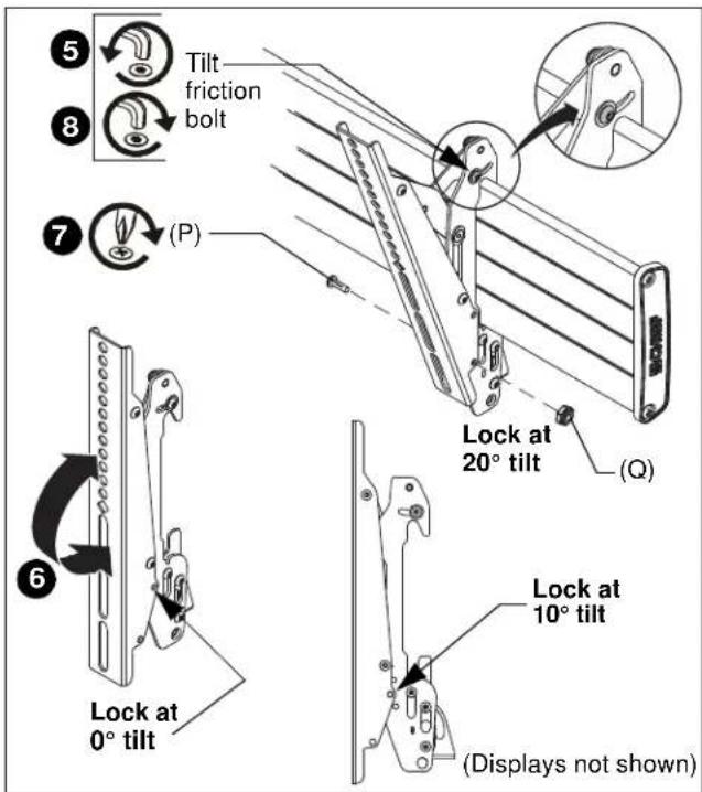
Figure 4
OPTIONAL: Security
- OPTIONAL: Add padlock (not included) to each interface bracket to lock display to mounting rail. (See Figure 5)
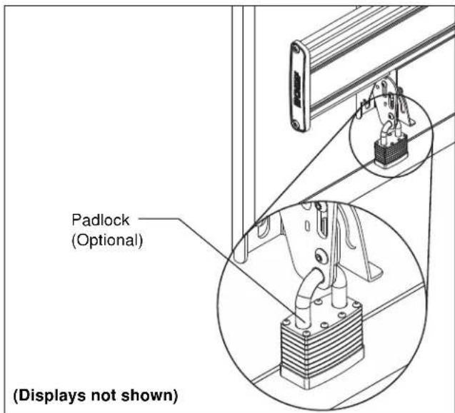
Figure 5
DIMENSIONS
![2.54 [64.6] 1.75 [44.5] 0.49 [12.5] 1.97 [50.0] 0.63 [15.9] 7.87 [200.0] 15.75 [400.0] 0.69 [17.5] 0.34 [8.7] 1.59 [40.5] 6.00 [152.4] 2.41 [61.1] 3.13 [79.6] 3/4" TOTAL HEIGHT ADJUST 3/4" TOTAL IN/OUT ADJUSTMENT 3/4" TOTAL IN/OUT ADJUSTMENT ADJUSTMENTS SHOWN AT MIDPOIN1 DIMENSIONS: INCHES [MILLIMET…](/content/2026/06/1202730/images/986e1e18beec5c8032dcd558f6441a9f4e2c9502f6ca6714b01a86925a8f7e5c.jpg)
LEGEND
 | Tighten Fastener |  | Phillips Screwdriver |
| Apretar elemento de fijación | Destornillador Phillips | ||
| Befestigungsteil festziehen | Kreuzschlitzschraubendreher | ||
| Apertar fixador | Chave de fendas Phillips | ||
| Serrare il fissaggio | Cacciavite a stella | ||
| Bevestiging vastdraaien | Kruiskopschroevendraaier | ||
| Serrez les fixations | Tournevis à pointe cruciforme | ||
 | Loosen Fastener |  | Open-Ended Wrench |
| Aflojar elemento de fijación | Llave de boca | ||
| Befestigungsteil lösen | Gabelschlüssel | ||
| Desapertar fixador | Chave de bocas | ||
| Allentare il fissaggio | Chiave a punte aperte | ||
| Bevestiging losdraaien | Steeksleutel | ||
| Desserrez les fixations | Clé à fourche |
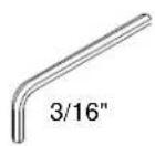
TOOLS REQUIRED FOR INSTALLATION - FMSIML

PARTS - FMSIML

DISPLAY ATTACH HARDWARE BAG
(Letters correspond to letters on bag)

A (4) M6 x 12mm

B (4) M6 x 16mm

C (4) M6 x 30mm

D (4) 1/4"

E (4) .750x.344x.500

F (4) M8 x 12mm
G (4) M8 x 16mm

H (4) M8 x 25mm

I (2) 1/4-20 x 1-1/4"

J (1) [Right interface bracket]

K (1) [Left interface bracket]
INSTALL INTERFACE BRACKETS TO DISPLAYS
- Place displays face down on a soft, non-abrasive surface.

WARNING: IMPROPER INSTALLATION CAN LEAD TO DISPLAY FALLING CAUSING SERIOUS PERSONAL INJURY OR DAMAGE TO EQUIPMENT! Using screws of improper size may damage your display. Properly sized screws will easily and completely thread into display mounting holes. If spacers are required, be sure to use longer screws of the same diameter.
-
Select screw diameter by examining hardware (A-C and F-H) and comparing with mounting holes on display. (See Figure 6)
-
Select spacers:
- Spacers are NOT____ required if mounting holes are not recessed and interface brackets (J and K) can lay flat against display.
- Spacers (E) ARE required if mounting holes are recessed, or if protrusions prevent interface brackets (J and K) from laying flat.
- Select screw length: (See Figure 6)
- By hand, insert SHORTEST length screw of selected diameter (A or F) through 1/4" washer (D), bracket (J or K), selected spacer (E, if required), into display mounting hole. Do NOT thread screw into hole at this time.
- Proper screw length requires base of screw head to protrude above flat washer a distance equal to or greater than the screw diameter. If screw length is inadequate, select longer screw. Select shortest screw which will protrude the required distance.
- Align the center of the interface brackets (J and K) with center of screen. (See Figure 6)
NOTE: The diamond-shape hole in the bracket corresponds to the center of the mount.
- Use selected screws (A-C or F-H), washers (D) and spacers (E), if necessary, to connect interface brackets (J and K) to back of display. (See Figure 6)

Figure 6
ATTACH DISPLAYS TO MOUNTING RAIL

WARNING: IMPROPER INSTALLATION CAN LEAD TO DISPLAY FALLING CAUSING SERIOUS PERSONAL INJURY OR DAMAGE TO EQUIPMENT! The displays must be located approximately evenly across the length of the rail.
- Ensure that the latch mechanisms on interface brackets (J and K) are already raised to the OPEN position. (See Figure 7)

CAUTION: BEFORE adding displays to the mounting rails, ensure end caps (FMSECAP) are in place at BOTH ends of mounting rail following instructions included with the FMSECAP.
- While supporting both sides of display, lower display onto mounting rail, hooking top of interface brackets onto top of mounting rail. (See Figure 7)
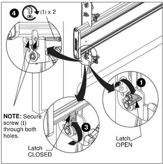
Figure 7
- Raise latch on interface bracket and close into place against mounting rail. (See Figure 7)
- Fasten latch into place using one 1/4-20 x 1-1/4" socket head screw (I). (See Figure 7)
NOTE: Socket head screws (I) must engage through both holes to be fully secured. (See Figure 7)
- Repeat for each interface bracket on the mounting rail.
Interface Bracket Adjustment

CAUTION: ALWAYS keep a small distance between screens when making adjustments! Damage to screens possible if placed too close together.
- Move displays so that screens are nearly flush and level with each other.
- Use upper knob on back of interface brackets (J and K) to adjust the height of each display. (See Figure 8)
NOTE: Adjust both brackets in order to maintain a level mount.
- Use middle and lower knobs on back of interface brackets (J and K) to make plumb adjustments to each display. (See Figure 8)

Figure 8
DIMENSIONS
![0.50 [12.7] 16.75 [425.5] 15.75 [400.0] 0.34 [8.6] 1.83 [46.6] 0.92 [23.3] 0.49 TYP. [12.5] 7.87 [200.0] 2.04 [51.7]](/content/2026/06/1202730/images/f970558dd394b801f7a6cd87a6d606c3fe89402765930e14edf2d678e0f8a93e.jpg)
FMSITL INCLUDES TWO UPRIGHT
![2.10 [53.4] 4.05 [103.0] 14.23 [361.6] 2.67 [67.8] 5.73 [145.7] 5.00 [127.0] 2.91 [74.0]](/content/2026/06/1202730/images/f5efc5b81be07da643cf9b53174da207dc8e9e0046eddcfae08d7bad05ea97aa.jpg)
FMSITL

DIMENSIONS: INCHES [MILLIMETERS]
LEGEND
 | Tighten Fastener |
| Apretar elemento de fijación | |
| Befestigungsteil festziehen | |
| Apertar fixador | |
| Serrare il fissaggio | |
| Bevestiging vastdraaien | |
| Serrez les fixations | |
 | Loosen Fastener |
| Aflojar elemento de fijación | |
| Befestigungsteil lösen | |
| Desapertar fixador | |
| Allentare il fissaggio | |
| Bevestiging losdraaien | |
| Desserrez les fixations | |
 | Hex-Head Wrench |
| Llave de cabeza hexagonal | |
| Sechskantschlüssel | |
| Chave de cabeça sextavada | |
| Chiave esagonale | |
| Zeskantsleutel | |
| Clé à tête hexagonale |
 | Phillips Screwdriver |
| Destornillador Phillips | |
| Kreuzschlitzschraubendreher | |
| Chave de fendas Phillips | |
| Cacciavite a stella | |
| Kruiskopschroevendraaier | |
| Tournevis à pointe cruciforme | |
 | Open-Ended Wrench |
| Llave de boca | |
| Gabelschlüssel | |
| Chave de bocas | |
| Chiave a punte aperte | |
| Steeksleutel | |
| Clé à fourche |
TOOLS REQUIRED FOR INSTALLATION - FMSITL


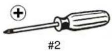

PARTS - FMSITL

DISPLAY ATTACH HARDWARE BAG
(Letters correspond to letters on bag)

A (8) M4x16mm

B (6) M4x20mm

C (6) M4x25mm

D (6) M5x16mm

E (6) M5x20mm

F (6) M5x25mm

G (6) M6x16mm

H (6) M6x25mm

I (6) M8x20mm

J (6) M8x30mm
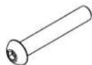
K (4) M8x50mm

L (8) .75x.323x.25"

M (8) .75x.344x.5"

N (8) [Univ. washer]

M5 (In section marked "N")
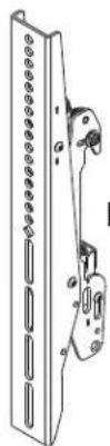
Q (2) [Interface bracket]
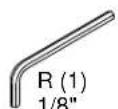
T (2) 10-24 x 5/8"

S (2) 10-24

10-24 × 2-1/4"
INSTALL INTERFACE BRACKETS TO DISPLAYS
- Lower the latch mechanism on each interface bracket (R). (See Figure 9)
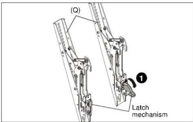
Figure 9
- Place displays face down on a soft, non-abrasive surface.

WARNING: IMPROPER INSTALLATION CAN LEAD TO DISPLAY FALLING CAUSING SERIOUS PERSONAL INJURY OR DAMAGE TO EQUIPMENT! Using screws of improper size may damage your display. Properly sized screws will easily and completely thread into display mounting holes. If spacers are required, be sure to use longer screws of the same diameter.
-
Select screw diameter by examining hardware (A-K) and comparing with mounting holes on display. (See Figure 10)
-
Select spacers:
-
Spacers are NOT required if mounting holes are not recessed and interface brackets (Q) can lay flat against display.
-
Spacers (L or M) ARE required if mounting holes are recessed, or if protrusions prevent interface brackets (Q) from laying flat.
-
Select screw length: (See Figure 10)
- By hand, insert SHORTEST length screw of selected diameter (A, D, G or I) through universal washer (N - if required), bracket (Q), selected spacer (L or M-if required), into display mounting hole. Do NOT thread screw into hole at this time.
IMPORTANT ! : The M8 screws (I, J and K) do NOT require a washer. Use the universal washer (N) ONLY with M4 (A-C), M5 (D-F) and M6 (G and H) screws.
- Proper screw length requires base of screw head to protrude above flat washer a distance equal to or greater than the screw diameter. If screw length is inadequate, select longer screw. Select shortest screw which will protrude the required distance.
- Align the center of the interface brackets (Q) with center of screen. (See Figure 10)
NOTE: The diamond-shape hole in the bracket corresponds to the vertical center of the mount.
- Use selected screws (A-K), universal washers (N-if required) and spacers (L or M-if required), to connect interface brackets (Q) to back of display. (See Figure 10)
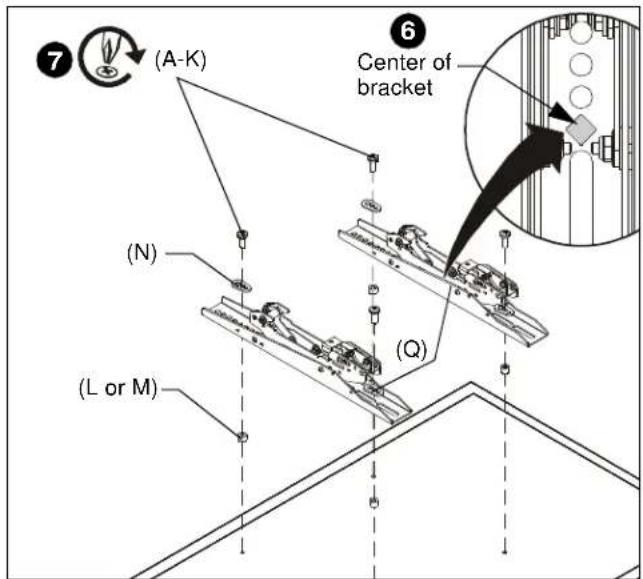
Figure 10
ATTACH DISPLAYS TO MOUNTING RAIL

WARNING: IMPROPER INSTALLATION CAN LEAD TO DISPLAY FALLING CAUSING SERIOUS PERSONAL INJURY OR DAMAGE TO EQUIPMENT! The displays must be located approximately evenly across the length of the rail.
- Ensure that the latch mechanisms on interface brackets (Q) are already lowered to OPEN position. (See Figure 11)

CAUTION: BEFORE adding displays to the mounting rails, ensure end caps (FMSECAP) are in place at BOTH ends of mounting rail following instructions included with the FMSECAP.
- While supporting both sides of display, lower display onto one side of mounting rail, hooking top of interface brackets onto front of mounting rail. (See Figure 11)
- Raise the latch mechanism on both interface brackets to lock bracket in place. (See Figure 11)

Figure 11
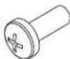
- Fasten bracket against mounting rail using one 10-24 x 5/8" button head cap screw (T). (See Figure 12)
- Repeat for other interface bracket.

Figure 12
Interface Bracket Adjustment

CAUTION: ALWAYS keep a small distance between screens when making adjustments! Damage to screens possible if placed too close together.
Tilt
The interface brackets allow 0° to 20° tilt, and can be locked at 0° , 10° and 20° tilt.
- If necessary, loosen button head tilt friction bolt (located on side of interface bracket). (See Figure)
- Adjust tilt as required. (See Figure)
- The tilt may be locked at 0°, 10° and 20° using one 10-24 x 2-1/4" Phillips head screw (U) and one 10-24 lock nut (S) per interface bracket. (See Figure )
- Tighten tilt friction bolt as necessary.

Figure 13
OPTIONAL: Security
- OPTIONAL: Add padlock (not included) to each interface bracket to lock display to menu board. (See Figure 14)

Figure 14
Installation Instructions

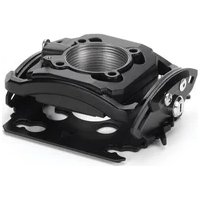

- INSTALLATION INSTRUCTIONS
- DISCLAIMER
- DEFINITIONS
- IMPORTANT SAFETY INSTRUCTIONS
- SAVE THESE INSTRUCTIONS
- TABLE OF CONTENTS
- TOOLS REQUIRED FOR INSTALLATION - FCASFP
- PARTS - FCASFP
- DISPLAY ATTACH HARDWARE BAG
- LOCKING HARDWARE KIT
- INSTALL INTERFACE BRACKETS TO DISPLAYS
- ATTACH DISPLAYS TO MOUNTING RAIL
- INTERFACE BRACKET ADJUSTMENT
- TILT
- OPTIONAL: SECURITY
- TOOLS REQUIRED FOR INSTALLATION - FMSIML
- PARTS - FMSIML
- TOOLS REQUIRED FOR INSTALLATION - FMSITL
- PARTS - FMSITL
Brand : Chief
Model : Fusion FCASFP
Category : Unspecified