
UTC-210 - Workstation Advantech - Free user manual and instructions
Find the device manual for free UTC-210 Advantech in PDF.

| Product Type | Opened-Frame Touch Computer |
| Brand | Advantech |
| Model | UTC-210 |
| Display Size | 10.1" TFT LCD with LED backlight |
| Resolution | 1280 x 800 |
| Brightness | 350 cd/m² |
| Touch Screen | Projected Capacitive, Glass Panel |
| Processor | Intel Celeron N3350 (Dual-Core 1.10 GHz) or Pentium N4200 (Quad-Core 1.10 GHz) |
| Memory | 1 x SO-DIMM DDR3L 1866 MHz, up to 8 GB |
| Storage | 1 x 2.5" SATA HDD bay + 1 x M.2 2242 SSD |
| Network | 2 x Gigabit Ethernet (supports Wake on LAN; 1 with PoE optional) |
| I/O Ports | 2 x USB 3.0, 2 x RS-232 COM (COM2 RS-232/422/485) |
| Audio | 1 x 2W stereo speaker |
| Expansion Slots | 1 x M.2 key2230, 1 x M.2 key2242 |
| Power Supply | 12 V/3 A ~ 24 V/1.5 A, 36W ITE adapter (PoE optional IEEE 802.3at/30W) |
| Dimensions (W x H x D) | 247 x 165.6 x 33.2 mm |
| Weight | 1.3 kg (2.87 lbs) |
| Operating Temperature | 0 - 40 °C (32 - 104 °F) |
| Relative Humidity | 10 - 95% @ 40°C non-condensing |
| Certification | CE, FCC |
| OS Support | Windows 10 IoT Enterprise 64-bit, Android 6.0, Linux Ubuntu 18.04 |
| Mounting Type | Rear mount (opened-frame) |
Frequently Asked Questions - UTC-210 Advantech
User questions about UTC-210 Advantech
0 question about this device. Answer the ones you know or ask your own.
Ask a new question about this device
Download the instructions for your Workstation in PDF format for free! Find your manual UTC-210 - Advantech and take your electronic device back in hand. On this page are published all the documents necessary for the use of your device. UTC-210 by Advantech.
USER MANUAL UTC-210 Advantech
natural_image
Illustration of four electronic circuit boards on an orange background, no text or symbols presentUTC-200 Series
7"/10.1"/21.5"/31.5"
Opened-Frame Touch Computer
Copyright
The documentation and the software included with this product are copyrighted 2019 by Advantech Co., Ltd. All rights are reserved. Advantech Co., Ltd. reserves the right to improve the products described in this manual at any time without notice. No part of this manual may be reproduced, copied, translated, or transmitted in any form or by any means without the prior written permission of Advantech Co., Ltd. The information provided in this manual is intended to be accurate and reliable. However, Advantech Co., Ltd. assumes no responsibility for its use, nor for any infringements of the rights of third parties that may result from its use.
Acknowledgements
Award is a trademark of Award Software International, Inc.
AMD is a trademark of Advanced Micro Devices.
Corning Gorilla is a trademark of Corning Inc.
Intel, Atom, Celeron, and Core are trademarks of Intel Corp.
IBM, PC/AT, PS/2 and VGA are trademarks of International Business Machines Corporation.
Microsoft Windows is a registered trademark of Microsoft Corp.
RTL is a trademark of Realtek Semiconductor Co., Ltd.
All other product names or trademarks are properties of their respective owners.
For more information about this or other Advantech products, please visit our website at http://www.advantech.com
For technical support and service, please visit our support website at
http://support.advantech.com
This manual is for UTC-200 Series
Declaration of Conformity
FCC Class A
Note!

This equipment has been tested and found to comply with the limits for a Class A digital device, pursuant to Part 15 of the FCC Rules. These limits are designed to provide reasonable protection against harmful interference when the equipment is operated in a commercial environment. This equipment generates, uses, and can radiate radio frequency energy and, if not installed and used in accordance with the instruction manual, may cause harmful interference to radio communications. Operation of this equipment in a residential area is likely to cause harmful interference, in such cases users will be required to correct the interference at their own expense.
Warning!
Any modifications to this device that are not approved by the relevant standards authority may void the authority granted to the user by the FCC to operate this equipment.

Packing List
Before installing the UTC system, check that the following materials have been included in the shipment:
■ UTC-200 Series Opened Frame Touch Computer
Accessories
- Adaptor
- Extended Brackets
– SATA cable (UTC-220/232 Only) - Packet of screws
If any of these items are missing or damaged, contact your distributor or sales representative immediately.
Technical Support and Assistance
- Visit the Advantech website at http://support.advantech.com to obtain the latest product information.
- Contact your distributor, sales representative, or Advantech's customer service center for technical support if you need additional assistance. Please have the following information ready before calling:
– Product name and serial number
– Description of your peripheral attachments
– Description of your software (operating system, version, application software, etc.)
– A complete description of the problem
- The exact wording of any error messages
Warnings
Warning! Batteries are at risk of exploding if incorrectly installed. Replace only with the same or equivalent type recommended by the manufacturer. Dispose of used batteries according to the manufacturer's instructions.

Warning! ■ Input voltage rated 12V/7A (UTC-207/210/220)

■ Input voltage rated 100 \~ 240 VAC 50/60 Hz for UTC-232
Use a 3V/195mA lithium battery
- Packing: The unit should be carried with both hands and handled
■ Maintenance: Use only approved products or a dry applicator to
- CompactFlash: Turn off the system power before inserting or removing the CompactFlash storage card.
Contact information
Manufacturer
Advantech Co., Ltd.
No.1, Alley 20, Lane 26, Rueiguang Road Neihu District, Taipei, Taiwan 114, R.O.C.
TEL: (02) 2792-7818
EU Distributor
Advantech Europe GmbH Kolberger Straße 7 D-40599 Düsseldorf, Germany
Tel: 49-211-97477350
Fax: 49-211-97477300
Safety Instructions
- Read these safety instructions carefully.
- Retain this user manual for future reference.
- Disconnect the equipment from all AC outlets before cleaning. Use only a damp cloth for cleaning. Do not use liquid or spray detergents.
- For pluggable equipment, the power outlet socket must be located near the equipment and easily accessible.
- Protect the equipment from humidity.
- Place the equipment on a reliable surface during installation. Dropping or letting the equipment fall may cause damage.
- The openings of the enclosure are for air convection. Protect the equipment from overheating. Do not cover the openings.
- Ensure that the voltage is correct before connecting the equipment to a power outlet.
- Position the power cord away from high-traffic areas. Do not place anything over the power cord.
- All cautions and warnings on the equipment should be noted.
- If unused for a long time, disconnect the equipment from the power source to avoid damage from transient overvoltage.
- Never pour liquid into an opening. This may cause fire or electrical shock.
- Never open the equipment. For safety reasons, the equipment should be opened only by qualified service personnel.
- If one of the following occurs, have the equipment checked by authorized service personnel:
■ The power cord or plug is damaged.
■ Liquid has penetrated the equipment.
■ The equipment has been exposed to moisture.
The equipment is malfunctioning or does not operate according to the user manual.
■ The equipment has been dropped and damaged.
■ The equipment shows obvious signs of breakage.
-
Do not store the equipment in an environment where the temperature fluctuates below -20 °C (-4 °F) or above 60 °C (140 °F) as this may cause damage. The equipment should be stored in a controlled environment.
-
Batteries are at risk of exploding if incorrectly installed. Replace only with the same or equivalent type recommended by the manufacturer. Discard used batteries according to the manufacturer's instructions.
-
Use only the recommended mounting apparatus to avoid damage due to falling.
-
The sound pressure level at the operator position does not exceed 70 dB (A) in accordance with the IEC 704-1:1982.
DISCLAIMER: These instructions are provided according to IEC 704-1 standards. Advantech disclaims all responsibility for the accuracy of any statements contained herein.
Warning! Because of the risk of electric shock, do not remove the equipment

cover during operation or when connected to a power outlet.
Caution!

To avoid short circuits and otherwise damaging the device, do not allow fluids to come in contact with the device. If fluids are accidentally spilled on the equipment, remove the affected unit from service as soon as possible and contact service personnel to verify that personal safety is not compromised. If the computer clock is unable to maintain accurate time or the BIOS configuration resets to default, check the battery.
Caution!

Do not replace the battery yourself. Contact a qualified technician or your retailer. The computer is equipped with a battery-powered real-time clock circuit. There is a danger of explosion if the battery is incorrectly replaced. Replace only with same or equivalent type recommended by the manufacturer. Discard used batteries according to the manufacturer's instructions.
Content
Chapter 1....8
1.1 Introduction ...... 2
1.2 Specification....3
1.2.1 UTC-207 3
1.2.2 UTC-210 3
1.2.3 UTC-220 4
1.2.4 UTC-232 4
1.3 Dimensions ....5
1.3.1 UTC-207 5
1.3.2 UTC-210 5
1.3.3 UTC-220 6
1.3.4 UTC-232 6
Chapter 2....7
2.1 Feature Overview......8
2.1.1 UTC-207 8
2.1.2 UTC-210 9
2.1.3 UTC-220 11
2.1.4 UTC-232 12
2.2 UTC-200 M/B Onboard Connectors 14
2.2.1 PCM-8523 Apollolake M/B (For UTC-207G/210G) 14
2.2.2 MIO-5350 Apollolake M/B (For UTC-220G/232G)....15
2.2.3 MIO-5272 Skylake M/B (For UTC-220F/232F)....16
2.3 Setup Procedure 17
2.3.1 System Power On....17
2.3.2 BIOS Setup 17
2.3.3 System Software Installation 17
2.3.4 Driver Installation....17
Chapter 3....18
3.1 Introduction ...... 34
3.2 Installing a 2.5" SATA HDD/SSD(For UTC-220/232) 34
3.3 Installing a M.2 SSD (For UTC-207/210)....35
3.4 Installing a Memory Module for UTC-220/232 35
3.5 Installing a Memory Module for UTC-207/210 36
3.6 Installing a WiFi Mini PCIe/M.2 Card (Optional) 36
Chapter 4 ....57
4.1 Introduction ......58
4.2 Rear Mount ....58
Chapter 1
General Information
1.1 Introduction
UTC-200 series comes with a full range of screen sizes from 7" to 31.5". With its opened-frame, fanless and low power design, it's suitable to be embedded into any type of equipment as a HMI such as self-ordering, showroom interactive signage, self-service kiosks, and public service terminals, as well as to support diverse digital retail, hospitality, healthcare, education, entertainment, and information processing applications. Featuring a protective enclosure, advanced touchscreen technology, wireless capabilities, and rich I/O, the high-performance UTC series can also be integrated with a wide range of optional peripherals and accessories according to specific application requirement
1.2 Specification
1.2.1 UTC-207
| CPU | Intel® Celeron® N3350 (UTC-207G) | Intel® Pentium® N4200 (UTC-207G) | |
| Base Frequency | 1.10 GHz (Dual-Core) | 1.10 GHz (Quad-Core) | |
| Cache | L2 Cache 1MB | L2 Cache 2MB | |
| Memory | 1 x SO-DIMM DDR3L 1866 MHz up to 8 GB | 1 x SO-DIMM DDR3L 1866 MHz up to 8 GB | |
| Storage | 1 x M.2 2242 SSD | ||
| Network (LAN) | 2 x Gigabit Ethernet ports (Supports Wake on LAN) | ||
| 2 x RS-232 COM (COM2 RS-232/422/485) | |||
| I/O ports | 2 x USB3.0 / 2 x USB3.0 (optional) | ||
| 2 x Gigabit Ethernet ports (1 with PoE) | |||
| Stereo Speaker | 1 x 2W | ||
| Bus expansion | 1 x M.2 key2230, 1 x M.2 key2242 | ||
| Dimensions (W x H x D) | 180 x 116.5 x 32.5 mm | ||
| Weight | 0.95kg (2.09lbs) | ||
| OS Support | Win 10 IoT Enterprise 64bitAndroid 6.0Linux Ubuntu 18.04 | ||
| Environmental Specifications | Operating Temperature | 0 - 40 °C (32 - 104 °F)* | 0 - 40 °C (32 - 104 °F)* |
| Relative Humidity | 10 - 95% @ 40 °C non-condensing | ||
| Vibration | 0.5G | ||
| Shock | 10G peak acceleration (11 msec. duration) | ||
| Certification | CE, FCC | ||
| Power Supply | DC Input Rating | 12 V/3 A ~ 24 V/1.5 A, 36W ITE Adapter | |
| PoE | Optional IEEE 802.3at/30W | ||
| Power consumption | Typical: 25WMax.: 34W | ||
| LCD Display | Size/Type | 7* TFT LCD with LED backlight | |
| Max.Resolution | 800 x 480 | ||
| Max. Color | 262K | ||
| Pixel Pitch (um) | 192.6 x 179 | ||
| Brightness (cd/m2) | 450 | ||
| View Angle | 140°/ 160° | ||
| Touch Screen Option (PE/GE) | Type | Projected Capacitive. Glass Panel | |
| Light Transmission | 80% ± 5% / 90% | ||
| Controller | USB Interface | ||
1.2.2 UTC-210
| Processor System | CPU | Intel® Celeron® N3350 (UTC-210G) | Intel® Pentium® N4200 (UTC-210G) |
| Base Frequency | 1.10 GHz (Dual-Core) | 1.10 GHz (Quad-Core) | |
| Cache | L2 Cache 1MB | L2 Cache 2MB | |
| Memory | 1 x SO-DIMM DDR3L 1866 MHz up to 8 GB | 1 x SO-DIMM DDR3L 1866 MHz up to 8 GB | |
| Storage | 1 x 2.5 internal SATA storage bay / 1 x M.2 2242 SSD | ||
| Network (LAN) | 2 x Gigabit Ethernet ports (Supports Wake on LAN) | ||
| I/O ports | 2 x RS-232 COM (COM2 RS-232/422/485)2 x USB3.0 / 2 x USB3.0 (optional)2 x Gigabit Ethernet ports (1 with PoE) | ||
| Stereo Speaker | 1 x 2W | ||
| Bus expansion | 1 x M.2 key2230, 1 x M.2 key2242 | ||
| Dimensions (W x H x D) | 247 x 165.6 x 33.2 mm | ||
| Weight | 1.3kg (2.87lbs) | ||
| OS Support | Win 10 IoT Enterprise 64bitAndroid 6.0Linux Ubuntu 18.04 | ||
| Environmental Specifications | Operating Temperature | 0 - 40 °C (32 - 104 °F)* | 0 - 40 °C (32 - 104 °F)* |
| Relative Humidity | 10 - 95% @ 40 °C non-condensing | ||
| Vibration | 0.5G | ||
| Shock | 10G peak acceleration (11 msec. duration) | ||
| Certification | CE, FCC | ||
| Power Supply | DC Input Rating | 12 V/3 A - 24 V/1.5 A, 36W ITE Adapter | |
| PoE | Optional IEEE 802.3at/30W | ||
| Power consumption | Typical 25WMax. 34W | ||
| LCD Display | Size/Type | 10.1" TFT LCD with LED backlight | |
| Max.Resolution | 1280 x 800 | ||
| Max. Color | 16.7M | ||
| Pixel Pitch (um) | 169.5 x 169.5 | ||
| Brightness (cd/m2) | 350 | ||
| View Angle | 170°/ 170° | ||
| Touch Screen Option (PE/GE) | Type | Projected Capacitive. Glass Panel | |
| Light Transmission | 80% ± 5% / 90% | ||
| Controller | USB Interface | ||
1.2.3 UTC-220
| Processor System | CPU | Intel® CoreTM i5-6300U (UTC-220F) Intel® CoreTM i3-6100U (Available)* | Intel® Pentium® N4200 (UTC-220G) Intel® Atom® E3950 (Available)* |
| Base Frequency | 2.4GHz (Dual-Core) | 1.1 GHz (N4200/Quad-Core) 1.6 GHz (E3950/Quad-Core) | |
| Cache | L3 Cache 3MB | L2 Cache 2MB | |
| Memory | 2 x SO DIMM DDR3L 1600MHz up to 16 GB | 1 x SO-DIMM DDR3L 1867 MHz | |
| Storage | 1 x 2.5 internal SATA HDD bay | 1 x 2.5 internal SATA HDD bay | |
| Network (LAN) | 2 x Gigabit Ethernet ports (Supports Wake on LAN) | ||
| I/O ports | 2 x RS-232 COM (RS-422/485)* 2 x USB 2.0 / 2 x USB 3.0 2 x Gigabit Ethernet (RJ-45) 1 x VGA 1 x HDMI Audio Line-out x 1, Mic-in x 1 | 2 x RS-232 COM (RS-422/485)* 2 x USB 2.0 / 2 x USB 3.0 2 x Gigabit Ethernet (RJ-45) 1 x VGA 1 x HDMI Audio Line-out x 1, Mic-in x 1 | |
| Stereo Speaker | 10W x 2 (optional) | ||
| Bus expansion | Full-size MiniPCIe/mSATA | ||
| Dimensions (W x H x D) | 21.5": 515.04 x 310.91 x 42.20(mm) | ||
| Weight | 21.5": 5.8kg | ||
| OS Support | WES 7P 32bit WES 7E 32bit Windows Pro Embedded 7 SP1 64bit WEBS 64bit Windows Embedded 8.1 Industry Pro 64bit Win 10 IoT Enterprise Linux Ubuntu 16.04 | Win 10 IoT Enterprise Android 6.0 Linux Ubuntu 17.04 | |
| Environmental Specifications | Operating Temperature | 0 - 40°C (32 - 104°F) | |
| Relative Humidity | 10 - 95% @ 40°C non-condensing | ||
| Vibration | 0.5G | ||
| Shock | 5G peak acceleration (11 msec. duration) | ||
| EMC/ Safety | CE, FCC | ||
| Power Supply | Input Rating | 12 V/7 A (84 W ITE Adapter) | |
| Power consumption | Typical 45W Max. 65W | ||
| LCD Display | Size/Type | 21.5" TFT LCD with LED backlight | |
| Max.Resolution | 21.5": 1920 x 1080 | ||
| Max. Color | 16.7M | ||
| Pixel Pitch (um) | 21.5": 248.25 x 248.25 | ||
| Brightness (cd/m2) | 250 (Optional 400) | ||
| View Angle | 178°/178° | ||
| Touch Screen Option (PE/RE/GE) | Type | Projected Capacitive. Analog Resistive 5-wires / Glass Panel | |
| Light Transmission | 80% ± 2%/80% ± 5%/90% | ||
| Controller | USB Interface / USB Interface / - | ||
1.2.4 UTC-232
| CPU | Intel® CoreTM i5-6300U (UTC-232F) Intel® CoreTM i3-6100U (Available)* | Intel® Pentium N4200 (UTC-232G) Intel® Atom E3950 (Available)* | |
| Base Frequency | 2.4GHz (Dual-Core) | 1.1 GHz (N4200/Quad-Core) 1.6 GHz (E3950/Quad-Core) | |
| Cache | L3 Cache 3MB | L2 Cache 2MB | |
| Memory | 2 x SO DIMM DDR3L 1600MHz up to 16 GB | 1 x SO-DIMM DDR3L 1867 MHz | |
| Storage | 1 x 2.5 internal SATA HDD bay | 1 x 2.5 internal SATA HDD bay | |
| Network (LAN) | 2 x Gigabit Ethernet ports (Supports Wake on LAN) | ||
| 2 x RS-232 COM (RS-422/485)* | 2 x RS-232 COM (RS-422/485)* | ||
| 2 x USB 2.0 / 2 x USB 3.0 | 2 x USB 2.0 / 2 x USB 3.0 | ||
| I/O ports | 2 x Gigabit Ethernet (RJ-45) | 2 x Gigabit Ethernet (RJ-45) | |
| 1 x VGA | 1 x VGA | ||
| 1 x HDMI | 1 x HDMI | ||
| Audio Line-out x 1, Mic-in x 1 | Audio Line-out x 1, Mic-in x 1 | ||
| Stereo Speaker | 10W x 2 (optional) | ||
| Bus expansion | Full-size MiniPCIe/mSATA | ||
| Dimensions (W x H x D) | 760.80 x 455.25 x 57.6(mm) | ||
| Weight | 15kg | ||
| OS Support | WES 7P 32bit WES 7E 32bit Windows Pro Embedded 7 SP1 64bit WE8S 64bit Windows Embedded 8.1 Industry Pro 64bit Win 10 IoT Enterprise Linux Ubuntu 16.04 | Win 10 IoT Enterprise Android 6.0 Linux Ubuntu 17.04 | |
| Environmental Specifications | Operating Temperature | 0 - 40°C (32 - 104°F) | |
| Relative Humidity | 10 - 95% @ 40°C non-condensing | ||
| Vibration | 0.5G | ||
| Shock | 5G peak acceleration (11 msec. duration) | ||
| EMC/ Safety | CE, FCC | ||
| Power Supply | Input Rating | 12 V/7 A (84 W ITE Adapter) | |
| Power consumption | Typical 45W Max. 65W | ||
| LCD Display | Size/Type | 31.5" TFT LCD with LED backlight | |
| Max.Resolution | 1920 x 1080 | ||
| Max. Color | 16.7M | ||
| Pixel Pitch (um) | 363.75 x 363.75 | ||
| Brightness (cd/m2) | 300 (Optional 400) | ||
| View Angle | 178°/178° | ||
| Touch Screen Option (PE/RE/GE) | Type | Projected Capacitive. Glass Panel | |
| Light Transmission | 80% ± 2% / 80% ± 5% / 90% | ||
| Controller | USB Interface / USB Interface / - | ||
1.3 Dimensions
1.3.1 UTC-207
Dimensions
Unit: mm

1.3.2 UTC-210
Dimensions
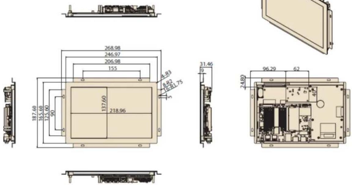
natural_image
Illustration of a rectangular panel or panel with mounting holes and a flat base (no text or symbols)Unit: mm
1.3.3 UTC-220
Dimensions

Unit: mm
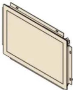
1.3.4 UTC-232
Dimensions
Unit: mm
Chapter 2
Quick Start Tour
2.1 Feature Overview
2.1.1 UTC-207
Front View

7" LCD Panel with PCap Touch
Rear View
Coastline I/O Locations
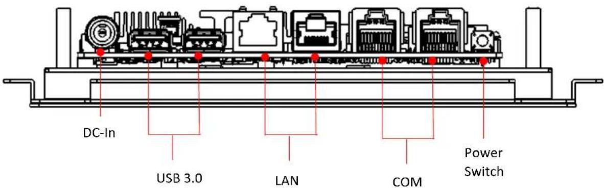
2.1.2 UTC-210
Front View
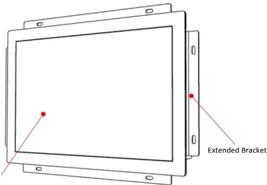
10" LCD Panel with PCap Touch
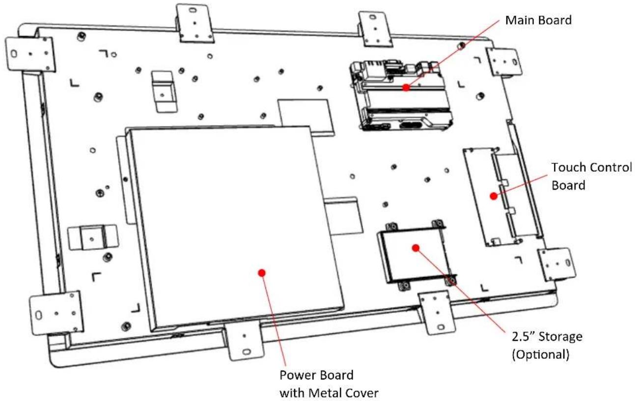
Rear View

Coastline I/O Locations

2.1.3 UTC-220
Front View

Rear View

Main Board Coastline I/O Locations

2.1.4 UTC-232
Front View

Rear View
Main Board Coastline I/O Locations

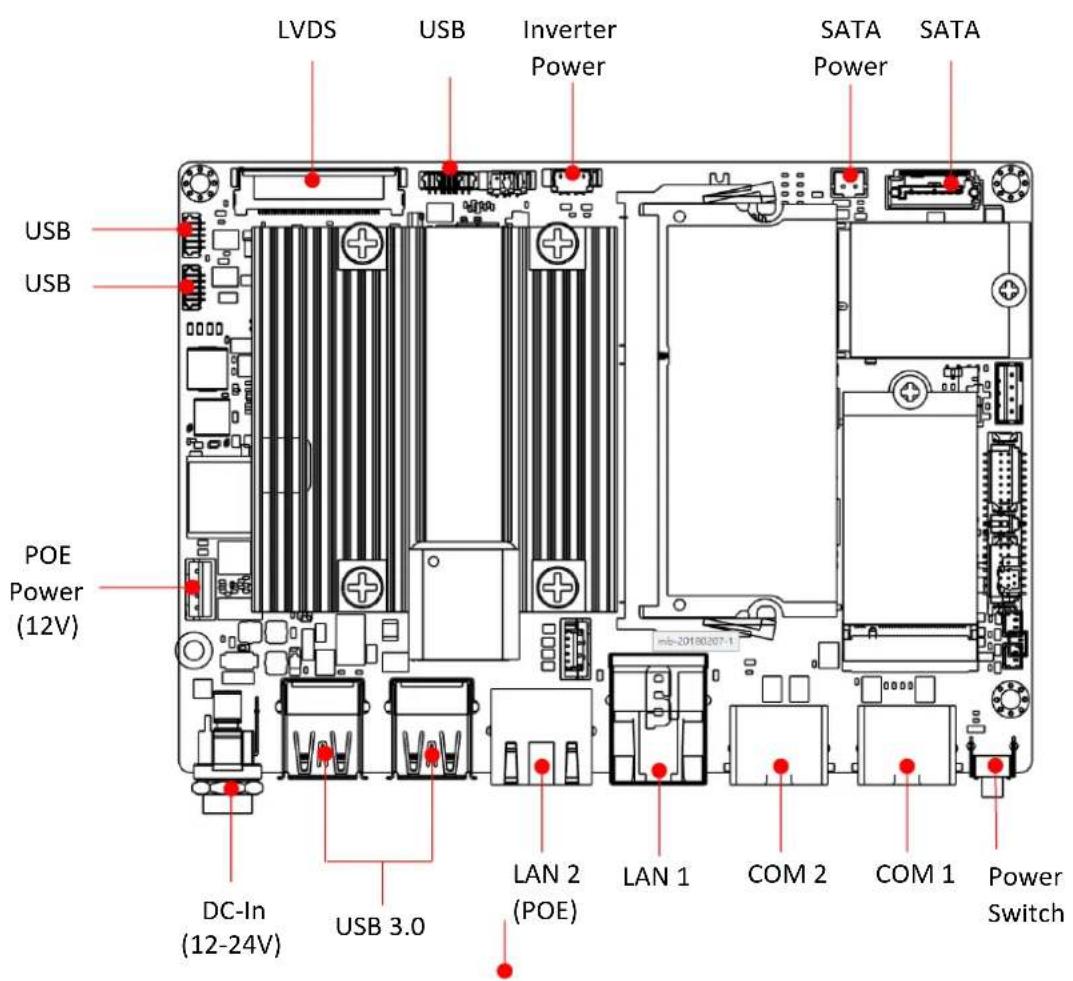
2.2 UTC-200 M/B Onboard Connectors
2.2.1 PCM-8523 Apollolake M/B (For UTC-207G/210G)
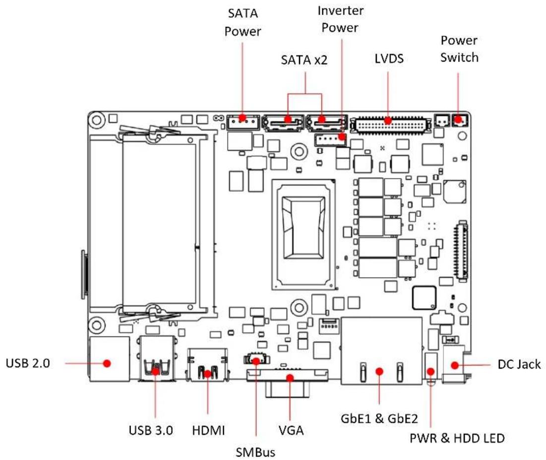
2.2.2 MIO-5350 Apollolake M/B (For UTC-220G/232G)
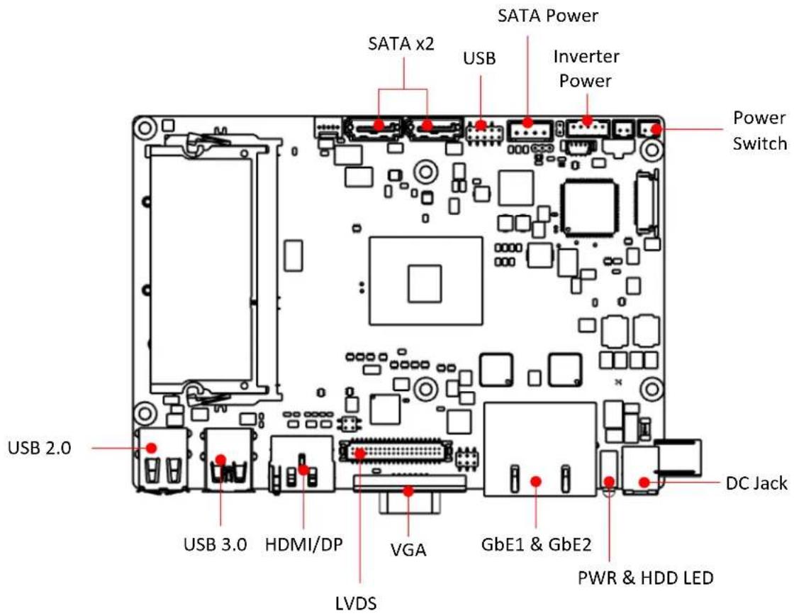

2.2.3 MIO-5272 Skylake M/B (For UTC-220F/232F)

2.3 Setup Procedure
2.3.1 System Power On
For the UTC-207/210/220 model, connect the system to a power adaptor with 12V/7A input voltage. For the UTC-232 models, connect the system to an AC power cable.
Hold power cords by the plugs ends only. Refer to Section 2.1 for the location of the DC/AC power input and power switch.
Connect the power cord to activate the system.
2.3.2 BIOS Setup
For most UTC series, the system setup and configuration will be completed by the dealer or system integrator prior to delivery. However, users may still need to access the BIOS setup program to adjust the system configuration, such as the date/time or hard drive type. The setup program is stored in read-only memory (ROM) and can be accessed following system reset or by pressing the "Del" key after powering on the computer. The settings selected in the setup program are recorded in CMOS RAM memory, which is backed up by a battery to ensure the settings are retained after the system is powered off. When booting up, the system compares the settings stored in CMOS RAM with the POST self test results. If a discrepancy is found, an error message is displayed on screen and users are prompted to run the setup program.
2.3.3 System Software Installation
Recent releases of operating systems from major vendors include setup programs that load automatically and guide users through hard disk preparation and operating system installation. Some distributors and system integrators may have already installed software prior to shipping the product.
Note! Before software or driver installation, the system must be equipped with additional storage that users must purchase separately.

2.3.4 Driver Installation
After installing the system software, users can set up the Ethernet, XGA, audio, and touchscreen functions.
Note! The relevant drivers and utilities are subject to change without notice.
Download the latest drivers for UTC series products from the Advantech

http://support.advantech.com or contact our application engineers for further assistance
website at
Chapter 3
Configuration Upgrade
3.1 Introduction
Advantech's UTC series systems are PC-based computers housed in an aluminum enclosure. To perform system maintenance or hardware upgrades, such as installing an HDD, DRAM, or CompactFlash (A/B models only), simply remove the unit's rear cover.
Warning! Do not remove the rear cover until you have verified that power is not flowing within the device. The system power should be switched off and the power cord unplugged before opening the device enclosure.

3.2 Installing a 2.5" SATA HDD/SSD(For UTC-220/232)
UTC systems feature a 2.5" SATA HDD bay reserved for customizable storage. To install a 2.5" SATA HDD, follow the steps below.
Insert the SATA HDD into the metal bracket and fasten in place with screws.
Use a power cable to connect the SATA HDD to the power supply unit.
Use a SATA data cable to connect the SATA HDD to the motherboard.
Replace the rear cover and tighten the screws.
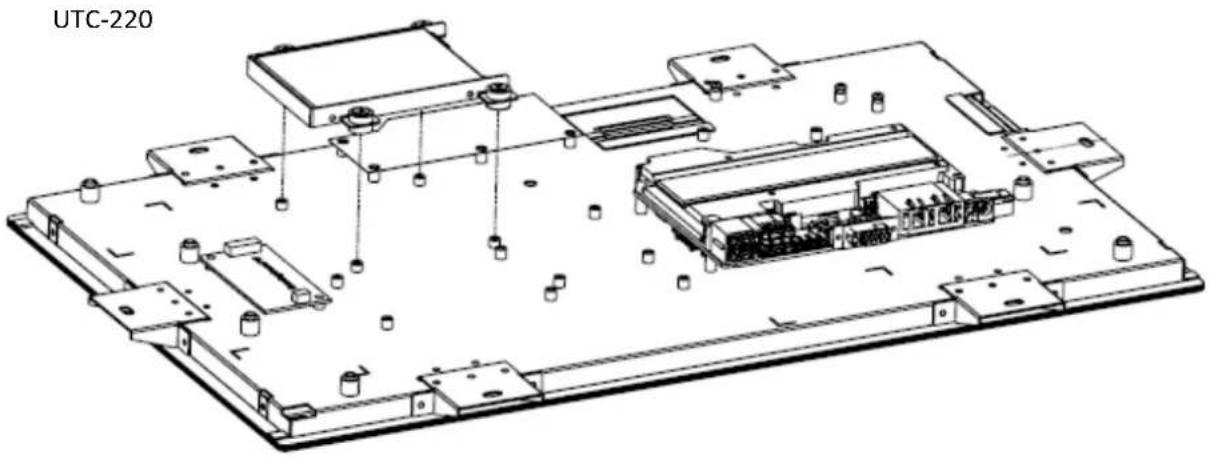
UTC-232
natural_image
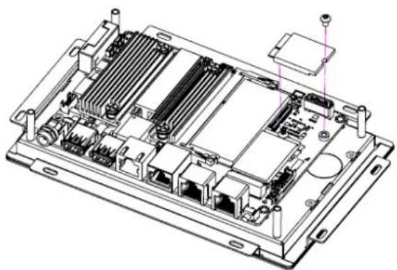
Technical line drawing of an electronic device chassis with components and mounting points (no text or labels)3.3 Installing a M.2 SSD (For UTC-207/210)
Insert the SSD into the M.2 slot located on the upside of the motherboard and fasten the screw.
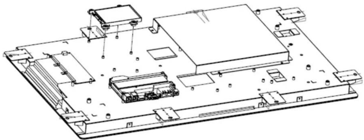
natural_image
Technical line drawing of an internal electronic device with visible ports, connectors, and a central module (no text or labels)3.4 Installing a Memory Module for UTC-220/232
Remove the 4 screws from the DRAM memory module heatsink. Turn the memory module over and remove the 2 screws on the underside. Install the DRAM module into the SODIMM socket.

natural_image
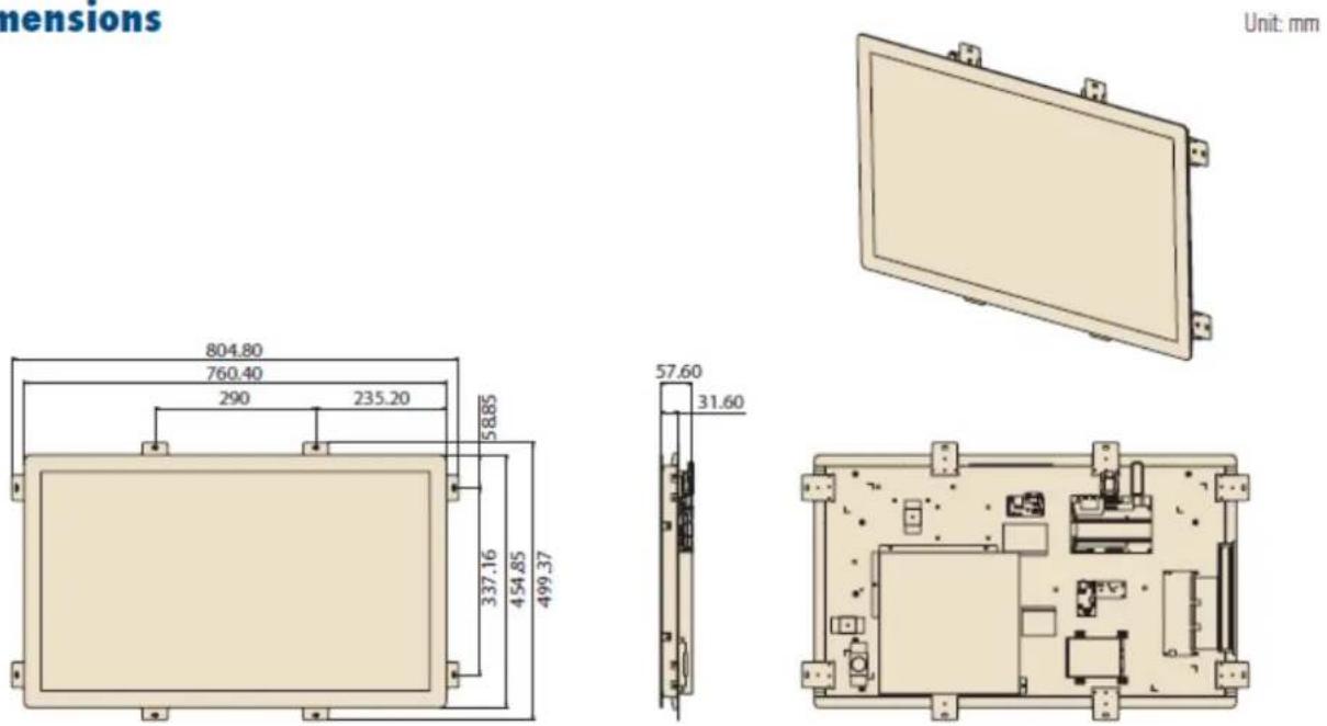
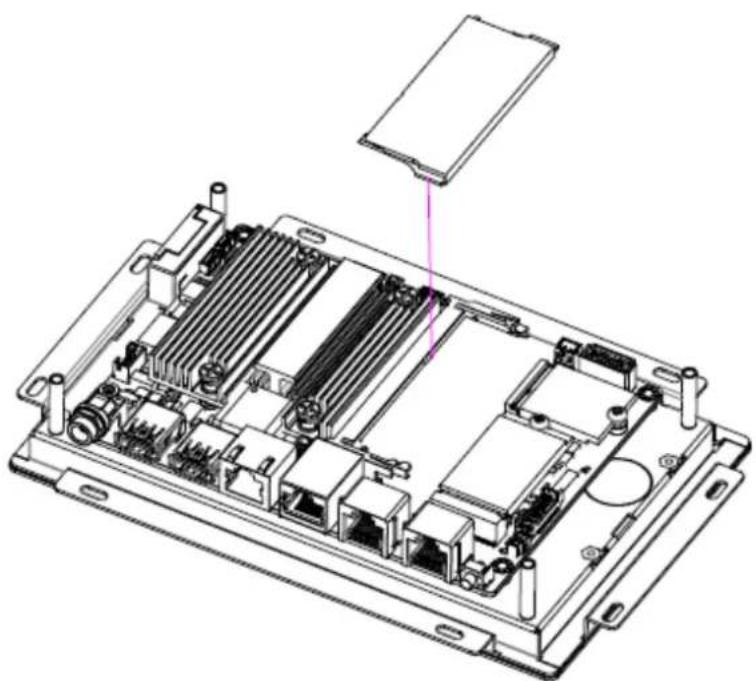
Technical line drawing of a mechanical assembly with no visible text or symbols3.5 Installing a Memory Module for UTC-207/210
Install the DRAM module into the SODIMM socket.
natural_image
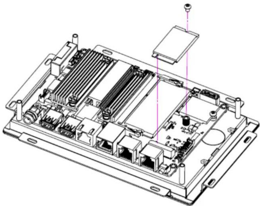
Technical line drawing of an internal electronic device casing with visible ports and connectors (no text or symbols)3.6 Installing a WiFi Mini PCIe/M.2 Card (Optional)
For UTC-220/232, remove the 4 screws holding the heatsink in place.
Insert the WLAN card into the mini PCIe slot located on the underside of the motherboard.
Connect a coaxial cable to ANT1 and ANT2 ports on the WLAN card.
For UTC-207/210, insert the WLAN card into the M.2 slot located on the upside of the motherboard.
Install the antenna on SMA connector on chassis exterior.
Note! If the motherboard is removed from the chassis and the cables detached and reattached, Pin 1 of the header can be located by aligning the red

side of the ribbon cable to the edge indicated by a small triangle marking on the PCB.

natural_image
Technical line drawing of a mechanical assembly with no visible text or symbolsMIO board for UTC-220/232
natural_image
Technical line drawing of an electronic device chassis with internal components and connectors (no text or symbols)PCM board for UTC-207/210
3.7 Installing a Back Cover for UTC-207/210 (Optional)
For UTC-207/210, could install the optional back cover.
Remove the washer from the DC-in connector and put the cover on the rear side. Fasten the screws at the rear side of the cover.
natural_image
Technical diagram of an electronic device showing internal components and mounting points (no text or labels)UTC-207
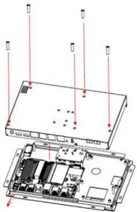
UTC-210
Chapter 4
Mounting Guide
4.1 Introduction
With UTC-200 opened-frame design, it's suitable to be embedded into any type of equipment and chassis with different mounting type.
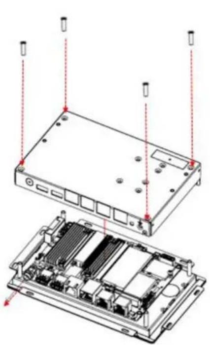
4.2 Rear Mount
Step 1. Make the cutout and add stand off from the rear side of the fixture

Fixture Front Side
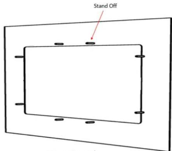
Fixture Rear Side
Step 2 Place the UTC-2xx from the rear side of the fixture and fasten the screws
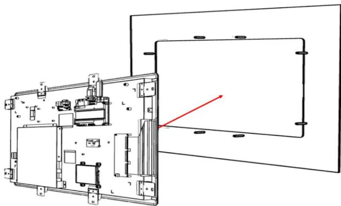
natural_image
Technical line drawing of an open electronic device with internal components and a red directional arrow indicating light or motion (no text or symbols present)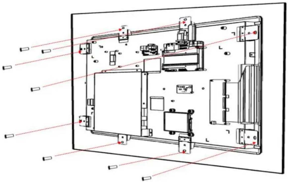
natural_image
Technical line drawing of an electronic device interior with labeled components and red alignment lines (no readable text or symbols)ADVANTECH
Enabling an Intelligent Planet
www.advantech.com
Please verify specifications before quoting. This guide is intended for reference purposes only.
All product specifications are subject to change without notice.
No part of this publication may be reproduced in any form or by any means, such as electronically, by photocopying, recording, or otherwise, without prior written permission from the publisher.
All brand and product names are trademarks or registered trademarks of their respective companies.
© Advantech Co., Ltd. 2017
- UTC-200 Series
- Copyright
- Acknowledgements
- Declaration of Conformity
- FCC Class A
- Note!
- Warning!
- Packing List
- Technical Support and Assistance
- Warnings
- Contact information
- Manufacturer
- EU Distributor
- Safety Instructions
- Content
- Chapter 1....8
- Chapter 2....7
- Chapter 3....18
- Chapter 4 ....57
- Chapter 1
- General Information
- Introduction
- Specification
- UTC-207
- UTC-210
- Dimensions
- UTC-207
- UTC-210
- UTC-220
- UTC-232
- Chapter 2
- Feature Overview
- UTC-207
- Coastline I/O Locations
- UTC-210
- UTC-220
- Main Board Coastline I/O Locations
- UTC-232
- Front View
- UTC-200 M/B Onboard Connectors
- PCM-8523 Apollolake M/B (For UTC-207G/210G)
- Setup Procedure
- System Power On
- BIOS Setup
- System Software Installation
- Driver Installation
- Chapter 3
- Configuration Upgrade
- Introduction
- Installing a 2.5" SATA HDD/SSD(For UTC-220/232)
- Installing a M.2 SSD (For UTC-207/210)
- Installing a Memory Module for UTC-220/232
- Installing a Memory Module for UTC-207/210
- Installing a WiFi Mini PCIe/M.2 Card (Optional)
- Installing a Back Cover for UTC-207/210 (Optional)
- Chapter 4
- Mounting Guide
- Introduction
- Rear Mount
- ADVANTECH
- www.advantech.com
Brand : Advantech
Model : UTC-210
Category : Workstation