VSkyCube - NAS Promise Technology - Free user manual and instructions
Find the device manual for free VSkyCube Promise Technology in PDF.


| Product Type | Hyper-converged infrastructure (NAS, compute, storage, networking) |
| Management | Web-based VSkyView management portal (HTTPS, port 443); default credentials admin/admin |
| Virtualization | KVM-based; supports launching instances (VMs) from images, volumes, or ISO; live migration supported |
| Storage | Software-defined storage; RAIN datastores for fault tolerance; supports volume and snapshot management |
| Networking | Built-in virtual switch; supports internal/external networks, routers, load balancers, floating IPs |
| High Availability | Cluster HA with VIP arbiter; automatic instance migration; node roles: VIP Controller, Controller, Worker |
| Security | User management; security groups (firewall rules); SSH key pairs; HTTPS access |
| Scalability | Scale out by adding nodes one at a time; supports up to multiple nodes in a cluster |
| Monitoring | Node, instance, and datastore monitoring; event logs and email alerts |
| Upgrade | Cluster (VSkyCube) and portal (VSkyView) upgrades via web interface; minor upgrades live |
| Orchestration | Heat-compatible; supports AWS CloudFormation and HOT templates for stack deployment |
| Dimensions (estimated) | Standard 1U rackmount form factor (approx. 44.5 x 43.5 x 4.3 cm) |
| Weight (estimated) | Approximately 10-15 kg depending on configuration |
| Power Supply (estimated) | Dual redundant hot-swappable; typical 300-500W per unit |
Frequently Asked Questions - VSkyCube Promise Technology
User questions about VSkyCube Promise Technology
0 question about this device. Answer the ones you know or ask your own.
Ask a new question about this device
Download the instructions for your NAS in PDF format for free! Find your manual VSkyCube - Promise Technology and take your electronic device back in hand. On this page are published all the documents necessary for the use of your device. VSkyCube by Promise Technology.
USER MANUAL VSkyCube Promise Technology
VSkyCube & VSkyView User Guide
Document Revision: v1.1
Nov 2nd, 2016
Contents
- Chapter 1. Overview ...... 1
- Chapter 2. VSkyView User Interface Introducon .... 2
2.1. Start Using the VSkyView Management Portal 2
2.2. Physical View.... 3
2.3. VSkyView System Setngs.... 3
2.3.1. User Management 4
2.3.2. Email Server (SMTP) Conguraon 4
2.3.3. Alert Email Conguraon 4
2.3.4. VSkyView Logs 5
2.3.5. VSkyView System Informaon....6
2.4. Personal Sengs....6
2.5. Cluster View 8
- Chapter 3. Host Management.... 13
3.1. Host Acons.... 13
3.2. Obtain the IP Address of the VSkyCube Host.... 15
- Chapter 4. Cluster Management.... 18
4.1. Create a Cluster 18
4.2. Trouble Shoong.... 22
4.3. Two Network Segment Interface Seng.... 23
4.4. Cluster Management....24
4.4.1. Register Cluster 24
4.4.2. Unregister Cluster 25
4.4.3. Add Hosts to the Selected Cluster 25
4.4.4. Retry Failed Hosts....26
4.4.5. Edit Cluster 27
4.4.6. Change Cluster Password....27
4.4.7. Delete Cluster 27
4.4.8. Reboot All Nodes....28
4.4.9. Shut Down All Nodes 28
4.5. Node Management.... 28
4.5.1. Node Details....29
4.5.2. Edit Node 29
4.5.3. Retry Failed Host 29
4.5.4. Delete Node 29
4.5.5. Network Sengs....30
4.5.6. Reboot Node 31
4.5.7. Shut Down Node 31
4.5.8. Change Node to Controller/Change Node to Worker 31
4.5.9. Node Deploy Logs 32
4.6. Cluster Node CLI Tool.... 34
4.6.1. Warning for Changing Node Network Sengs....37
4.6.2. Transfer VIP via Node CLI 37
4.6.3. Remove from Isolaon.... 38
4.7. Cluster Services.... 38
4.7.1. Cluster Service Sengs....39
4.8. Cluster High Availability 40
4.8.1. Cluster High Availability Requirements 40
4.8.2. Cluster High Availability Scenarios 40
4.8.3. Workow of High Availability and Recovery (VIP Controller) 41
4.8.4. Workow of High Availability and Recovery (Controller and Worker) 44
4.9. Event and Log.... 45
4.9.1. Email Nocaon....46
5. Chapter 5. Application Management.... 47
5.1. Create an Applicaon 47
5.2. Applicaon Wizard....48
5.3. Applicaon Acons....49
6. Chapter 6. Virtual Machine Management .... 52
6.1. Launch an Instance 52
6.2. Instance Boot Source.... 55
6.2.1. Boot from image 56
6.2.2. Boot from instance snapshot 56
6.2.3. Boot from volume 57
6.2.4. Boot from ISO (Linux)....57
6.2.5. Boot from ISO (Windows)....61
6.3. Instance Acons....71
6.4. Accessing Instances 74
6.5. Images 76
6.5.1. Create Image 76
6.5.2. Creang an Amazon Machine Image (AMI) 78
6.5.3. Image Acons....81
6.5.4. Image Life Cycle....81
6.6. Flavors 82
6.7. Key Pairs 83
6.8. Security Groups.... 86
6.8.1. Manage Security Group 86
6.8.2. Set Up Security Group Rules for accessing Instances....87
6.9. Resource Rao 91
6.10. Floang IPs 92
6.10.1. Associate Floang IP to Instance 92
6.10.2. Manage Floang IP 94
7. Chapter 7. Networking....95
7.1. Network Topology....95
7.2. Build a Basic Network Environment....96
7.3. Network Wizard 105
7.4. Manage External Network 107
7.5. Manage Internal Networks....108
7.5.1. Share Internal Network with Other Applicaons 109
7.6. Manage Subnets 111
7.7. Ports 112
7.8. Manage Routers and Interfaces....112
7.8.1. Routers.... 113
7.8.2. Use Ping on the Router to Verify the Network Connecon 113
7.8.3. Interfaces....114
7.9. Stac Routes 118
7.10. Load Balancer 121
7.10.1. Build a Basic Load Balancer for a Website 122
7.10.2. Load Balancer Pool....134
7.10.3. VIP 135
7.10.4. Member....136
7.10.5. Health Monitor....136
8. Chapter 8. Storage ...... 138
8.1. Physical Pool.... 138
8.2. Cluster Storage....139
8.2.1. Image Storage 139
8.2.1.1. Create a Datastore for Image Storage....141
8.2.1.2. Create a RAIN Datastore for Image Storage (Cluster HA)....141
8.2.2. Compute Storage 142
8.3. Applicaon Pool 143
8.4. Datastores 144
8.4.1. Datastore Properes and Hardware Requirements 144
8.4.2. Check Hardware Disk Resources 147
8.4.3. Create Datastore 148
8.4.4. Troubleshoong 149
8.5. Volume 150
8.5.1. Create Volume....150
8.5.2. Attach a Volume to an Instance....151
8.5.3. Volume Source 153
8.5.4. How to Check Volume Source aer Creaon 155
8.5.5. Volume Acons 157
8.5.6. Volume Snapshot 158
8.5.7. Troubleshoong 158
9. Chapter 9. Monitoring.... 160
9.1. Nodes Monitoring.... 160
9.2. Instance Monitoring 160
9.3. Datastores Monitoring 161
10. Chapter 10. Stack (Orchestraon).... 162
10.1. Wring a Template 162
10.1.1. Basic Template....162
10.1.2. Template Input Parameters 163
10.1.3. Template Environment....166
10.2. Launching and Previewing a Stack 166
10.2.1. Template without Parameters 166
10.2.2. Template with Parameters.... 166
10.3. Stack Acons.... 170
10.4. Stack Resources 171
10.5. Stack Snapshots 172
10.6. Stack Events ...... 173
10.7. Resource Types ...... 174
11. Chapter 11. Upgrade.... 175
11.1. Cluster (VSkyCube) Upgrade 175
11.2. Portal (VSkyView) Upgrade 175
1. Chapter 1. Overview
This VSkyCube/View User Guide provides informaon on how to conjure and use the VSkyCube plaorm with the VSkyView management portal. Before you can begin using the VSkyCube plaorm, you need to install both VSkyView and VSkyCube. For details on how to install the portal, please refer to the VSkyView & VSkyCube Quick Start Guide.
VSkyCube, a hyper-converged system, integrates compute, networking, and storage in a box that is capable of providing a cost-eeceve and exible infrastructure for IT in deploying a variety of applicaons.
In its simplest form, a VSkyCube box can be used as a small data center that runs one or more applicaons with storage allocated to each applicaon, as illustrated below.

flowchart
graph TD
    subgraph_ComputePool["Compute Pool"]
        CPUPool1["CPU pool"] --> VM1["VM"]
        CPUPool2["CPU pool"] --> VM2["VM"]
        CPUPool3["CPU pool"] --> VM3["VM"]
        CPUPool4["CPU pool"] --> VM4["VM"]
        CPUPool5["CPU pool"] --> VM5["VM"]
        CPUPool6["CPU pool"] --> VM6["VM"]
        CPUPool7["CPU pool"] --> VM7["VM"]
        CPUPool8["CPU pool"] --> VM8["VM"]
        CPUPool9["CPU pool"] --> VM9["VM"]
    end

    subgraph_StoragePool["Storage Pool"]
        StoragePool1["Storage Pools"] --> StoragePool2["Storage Pools"]
        StoragePool3["Storage Pools"] --> StoragePool4["Storage Pools"]
    end

    subgraph_Node1["Node 1"]
        Node1 --> CPUPool1
        Node1 --> CPUPool2
        Node1 --> CPUPool3
    end

    subgraph_NodeN["Node N"]
        NodeN --> CPUPool4
        NodeN --> CPUPool5
        NodeN --> CPUPool6
    end

    subgraph_PhysicalNetwork["Physical Network"]
        PhysicalNetwork --> VirtualSwitch["Virtual Switch"]
    end

    subgraph_StoragePool["Storage Pool"]
        StoragePool1 --> VolVol
        StoragePool2 --> VolVol
        StoragePool3 --> VolVol
        StoragePool4 --> VolVol
        StoragePool5 --> VolVol
    end

    style PhysicalNetwork fill:#000,stroke:#fff,color:#fff
    style StoragePool fill:#f00,stroke:#000,color:#fff
In a single node case (Node 1), CPU cores and memory form the compute pool and all disks form the storage pool. Applicaons, in the form of VM, can then be launched aer they are provisioned with compute and storage resources. Other more complex deployments with mul-er applicaons are also possible.
The VSkyCube can be scaled-out by adding nodes to the cluster, one node at a me. Adding a node to a cluster is easy and non-disruptive. Aer new nodes join a cluster, the cluster is managed and used in the same way as the single node system. All resources; compute, storage, and network, are pooled for best usage according to demand.
2. Chapter 2. VSkyView User Interface Introducon
This chapter is a VSkyView UI introducon. Aer installaon, the VSkyView service will automatically run in the background. Follow the steps in Chapter 2.1 to log in to VSkyView. There are four major components in VSkyView: Physical view, VSkyView system sengs, Personal sengs, and Cluster view. These components will be introduced in Chapter 2.2 to 2.5.
2.1. Start Using the VSkyView Management Portal
Aer nishing the VSkyView installaon, log in to the VSkyView portal through the URL.
The URL would be https://

2.2. Physical View

Physical View is one of the two perspectives of the VSkyView interface; the other is Cluster View. Physical View shows the resources of the physical machines, which we call hosts. Aer cluster deployment, all selected hosts will be virtualized and transferred into nodes. Nodes are controlled by their clusters. Physical View displays two tabs: Topology and Hosts. For informaon about the Hosts tab, refer to Chapter 3. Host Management. For details on Cluster View, refer to 2.5 Cluster View.
2.3. VSkyView System Sengs

The gear icon 🧙 shown in the above picture, allows you to conjure the VSkyView System Sengs.
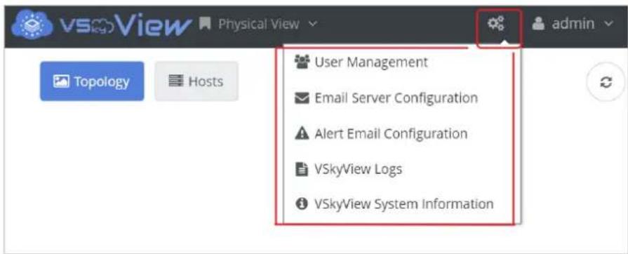
By clicking the gear icon ⚙ drop-down menu will appear allowing you to conjure VSkyView.
2.3.1. User Management
The User Management opon is where you can add, edit, or delete user accounts.
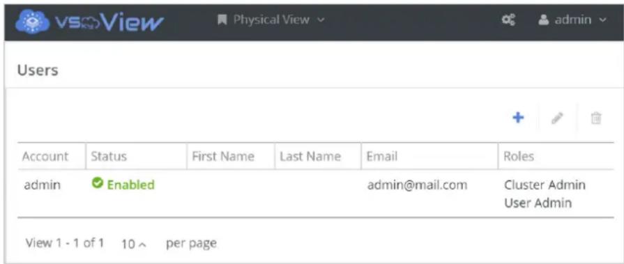
- To add a new user, click the plus icon.
- To edit user informaon, click the pencil icon.
- To delete a user, click the trashcan icon.


2.3.2. Email Server (SMTP) Conguraon
The Email Server (SMTP) Conguraon opon allows you to specify an email address for sending alert nocaons. When the window opens, type the following informaon.
- Hostname/IP Address: Enter the hostname or IP address of your SMTP server.
- Port: Type in the port number.

2.3.3. Alert Email Conguraon
The Alert Email Conguraon opon allows you to select the severity level (Crical, Error, Warning, or Info) for sending alert nocaons. By default, the alert nocaon is disabled. You will need to setup the 2.3.2 Email Server (SMTP) Conguraon to make alert email able to be sent.

If you wish to enable the nocaons, click Edit buon. When the window opens, type the following informaon.
- Alert Email: Choose enable or disable.
- Nocaon Level: Select the severity level for the alert nocaons.
- Email Receivers: Enter the email addresses that will receive the alert nocaons.
• Frequency: Select the frequency of nocaon.

Aer verifying the informaon, click Submit to apply the new sengs.
2.3.4. VSkyView Logs
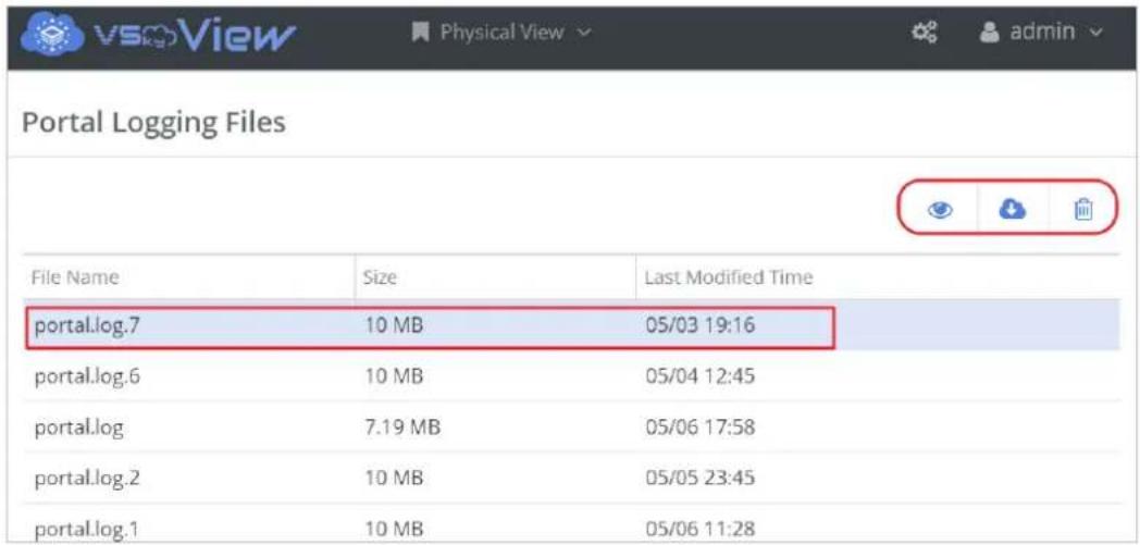
This window lists all the VSkyView logs. Click on a row to select a log, and then click an acon buon at the upper le of the table to view, download, or delete the selected log.
2.3.5. VSkyView System Informaon
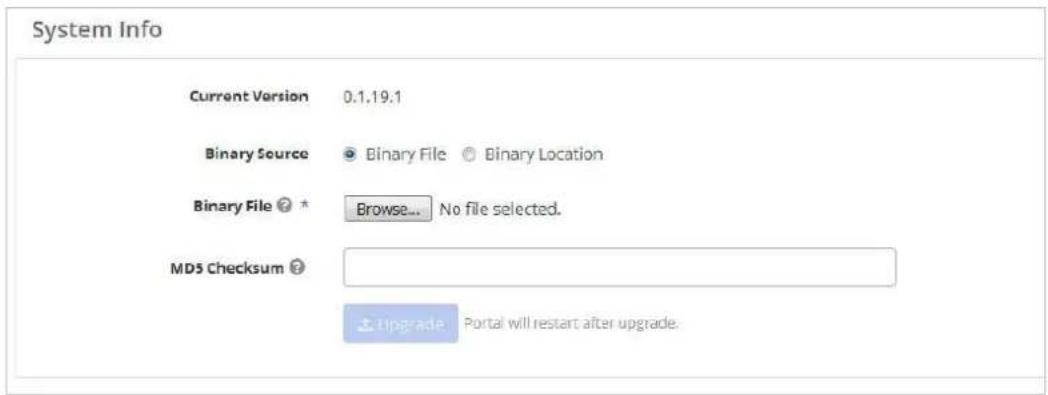
The VSkyView System Informaon opon shows the current version of VSkyView and allows you to upload released VSkyView packages to apply an upgrade.
2.4. Personal Sengs
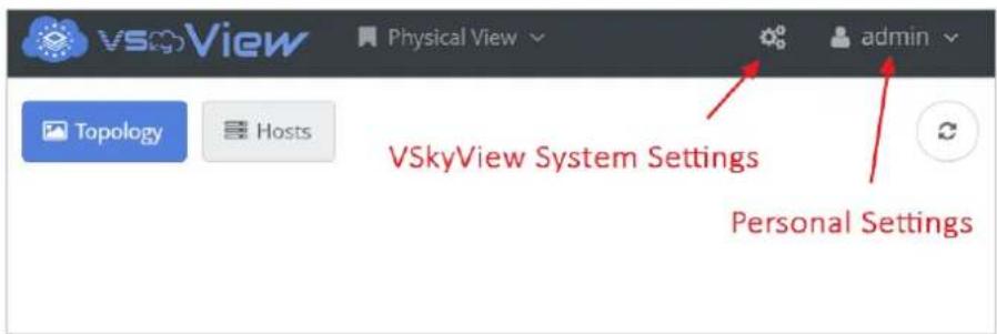
In the above picture, the icon 🙏 on the right is for Personal Sengs. These allow you to edit personal proles and to log out. By clicking the down-arrow icon ,a drop-down menu will appear allowing you to edit the Personal Sengs.

Edit Prole
The Edit Prole opon allows you to alter your basic informaon.

Change Password
The Change Password opon is for changing the password.

Sign Out
This opon allows you to sign out of the system. You are logged out immediately aer selecng the opon (no prompt or message).
2.5. Cluster View

When switching to Cluster View, there will be 5 items on the top bar. From le to right, they are View Switcher, Cluster Alerts, Cluster Tasks, VSkyView System Sengs, and Personal Sengs.
• View Switcher: Click to switch between Physical View and Cluster View.
- Cluster Alerts: a pop-up panel displays an alert summary for all clusters.
- Cluster Tasks: a pop-up panel displays a brief task summary for all clusters.
• VSkyView System Sengs and Personal Sengs were explained previously.
Click the VSkyCube logo to see two tabs on the right dashboard, Summary and Cluster Deployment.

Summary
Summary shows the basic informaon for deployed clusters, such as the numbers of nodes, the hard drives in the cluster, and the nodes and drive health status.
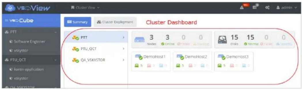
Cluster Deployment
The Cluster Deployment tab contains two seconds, Clusters and Nodes. The Clusters secon allows you to deploy the cluster and cluster-related acons. The Nodes secon lets you perform node-related acons. Refer to Chapter 4. Cluster Management for more informaon.

Cluster Directory
The le panel has the list of clusters and applicaons displayed in tree-view. Click on a cluster to display its informaon on the middle panel. You will see a variety of cluster informaon like hardware, instances, and resources (vCPU, RAM, and storage). In addition, it shows the hypervisor and applicaon summaries.
The rightmost panel presents the operaons and acons for the cluster. The next secon is an introducon to these operaons.

Cluster-Related Menu
The funcons in this menu will let us display important informaon, perform operaons, and make adjustments to the selected cluster.
Applicaon
• Conguraons: Lets you create and manage applicaons.
Storage
- Physical Pool: Displays a summary of physical storage, including the drive type, size, model, and serial number.
- Cluster Storage: Cluster storage includes two parts, image storage and compute storage. Image storage is for saving image les. The dashboard displays the image storage use/capacity summary. Compute storage is allocated for vDisk (VM-used disk) use. The dashboard displays the compute storage use/capacity summary.
Compute
- Flavors: VM resource templates, allows you to create customized avors besides the default avors.
- Images: An image is a collecon of les for a specific operang system (OS) that you use to create or rebuild a server. You can upload and manage images of the cluster.
- Key Pairs: Allows you to manage key pairs, which are secure shell (SSH) credenals injected into an instance when launched.
- Resource Rao: Allows you to set the resource rao of physical resources (CPU and RAM) to overprovision.
Networking
• Network Topology: Exhibits the whole cluster network architecture and topology diagram.
- External Network: A network segment typically used for instance Internet access. The buon allows you to create an external network for the cluster.
Monitoring
- Nodes: Displays the monitoring gures for physical nodes, including the CPU, load, memory, and network interface trac.
Event & Log
• Events: Shows the cluster events, alerts, and task records.
- Logs: Allows you to query or download the cluster logs.
Conguraon
• Service Seng: Allows you to manage the cluster-related service sengs.
- Cluster Upgrade: Allows you to upgrade the cluster version through this interface. It also shows the cluster upgrade history.
Applicaon Directory
Applicaons are listed below the cluster to which they belong. You can click an applicaon name to select it. The Informaon Dashboard of the selected applicaon will be shown on the right, including a variety of Applicaon Usage summaries, like Applicaon Pool, Volumes and Snapshots Capacity, Instances, vCPUs, RAM, and Floang IPs. If you want to change the applicaon resource quota, please refer to 5.3 Applicaon Acons. The rightmost panel contains the operaons related to applicaons.

Applicaon-Related Menu
Here is an introducon to applicaon-related operaons. These commands will be listed on the right side panel whenever an applicaon is selected.
Storage
• Applicaon Pool: Allows you to create an applicaon pool.
Compute
- Images: The same denion as a cluster image, however this one allows you to create and manage images that are exclusive to speci applicaons.
- Instances: Allows you to launch and manage virtual machines.
• Volumes: Allows you to create and manage persistent data volumes. - Security Groups: A set of network trac ltering rules that are applied to an instance. It can be regarded as a rewall. You can create a security group appropriate for each VM.
- Floang IPs: An IP address that can be associated with a VM so that the instance has the same public IP address each me that it boots. Allows you to manage oang IPs, such as to allocate/release and associate/disassociate oang IPs.
Networking
- Internal Networks: A network segment that is generally not accessible to end users or the public Internet, and is used for management of the instance. Allows you to create internal networks.
- Load Balancers: A load balancer is for distribution workloads based on conguraon. Load balancers can be created and managed here.
Monitoring
- Instances: Displays the monitoring data for instances, including the CPU, disk, memory, and network interface trac.
- Datastores: Displays the monitoring data of the datastores.
Orchestraon
- Stacks: Organizes the resources with templates.
• Resource Types: Aributes and properes of all supported resources.
For more informaon about the cluster/applicaon operaons, please refer to Chapter 4. Cluster Management and Chapter 5. Applicaon Management.
3. Chapter 3. Host Management
Use the informaon in this secon for host management.
3.1. Host Acons
Add Host
- In Physical View, switch to the Hosts tab. Click the + icon to create or add a new VSkyCube host.

-
The Create Host window appears. Enter the following informaon.
-
Alias Name: A name for the VSkyCube host.
- IP address: Enter the IP address of the VSkyCube host. See 3.2 Obtain the IP Address of the VSkyCube Host to obtain the IP address of host.
- Site: The locaon of the host (for example, Taipei). This eld is oponal. Site is a tag for you to classify hosts and can be changed in the future.

- Click Submit, the new host will be registered in VSkyView.
- The new host will also appear on the Topology page.
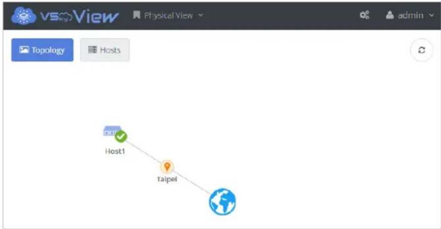
flowchart
graph TD
    A["Host1"] --> B["Taipei"]
    B --> C["Global"]
- Repeat Steps 1 to 4 to add other VSkyCube hosts.
Edit Hosts
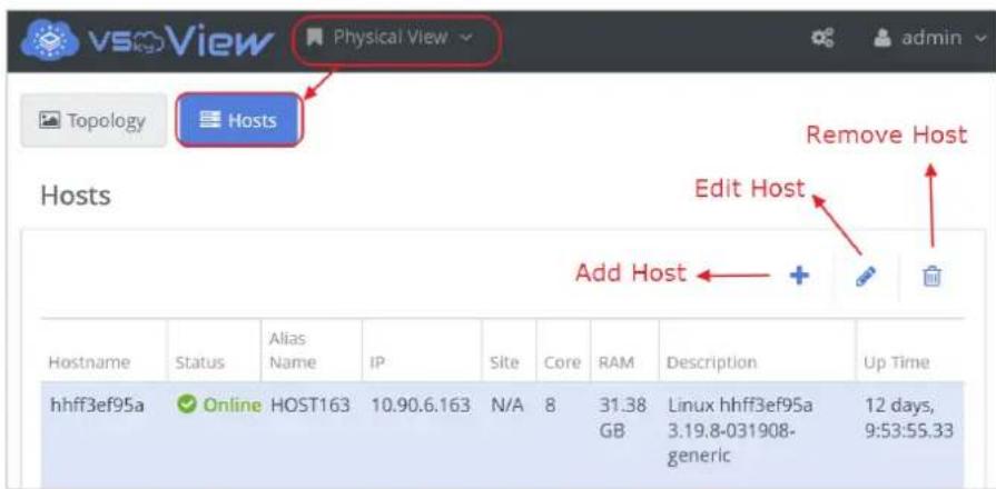
Switch to Physical View and select the Hosts tab. All the hosts will be shown in the table. Click the row to select a host, and then click the pencil buon to edit the selected host. If the selected host is a node in a cluster, you are not allowed to edit the alias name and IP here. See 4.5 Node Management.

Delete Hosts

Switch to Physical View and select the Hosts tab. All the hosts will be shown in the table. Click a row to select a host, and then click the trashcan icon 📄to delete a host. If the host is already a node in a cluster, you have to remove the node from the cluster rst. See 4.5 Node Management. If the host does not belong to any cluster, the host can be deleted.

3.2. Obtain the IP Address of the VSkyCube Host
Follow these steps to get the IP address of each VSkyCube host.
- Connect a keyboard and a monitor to the VSkyCube host. The following login window appears.

- Log in to the VSkyCube host.
Username: promise
Password: promisepromise
Note
The password can be changed aer deployment. See 4.6 Cluster Node CLI for more informaon.
Ubuntu 14.04.1 LTS hhe2f27608 tty1
hhe2f27608 login: promise
Password:
Last login: Wed Mar 23 16:53:21 CST 2016 on tty1
Welcome to Ubuntu 14.04.1 LTS (GNU/Linux 3.19.8-031908-generic x86_64)
* Documentation: https://help.ubuntu.com/
promise@hhe2f27608:~$ _
- Aer logging in, type ifcong to list the IP address of the 10GbE LAN port.
Noce
The IP address here is temporarily assigned by DHCP. It will be congured to a xed IP when deploying VSkyCube.
- The IP address is shown aer "inet addr:" In the following example, the IP address is 172.16.0.75.
Ubuntu 14.04.1 LTS hhe2f27608 tty1
hhe2f27608 login: promise
Password:
Last login: Wed Mar 23 16:53:21 CST 2016 on tty1
Welcome to Ubuntu 14.04.1 LTS (GNU/Linux 3.19.8-031908-generic x86_64)
* Documentation: https://help.ubuntu.com/
promise@hhe2f27608:~$ ifconfig
eth0 Link encap:Ethernet HWaddr 00:8c:fa:ef:f9:74
inet addr:172.16.0.75 Bcast:172.16.0.255 Mask:255.255.255.0
inet6 addr: fe80::28c:faff:feef:f974/64 Scope:Link
UP BROADCAST RUNNING MULTICAST MTU:1500 Metric:1
RX packets:1163 errors:0 dropped:0 overruns:0 frame:0
TX packets:60 errors:0 dropped:0 overruns:0 carrier:0
collisions:0 txqueuelen:1000
RX bytes:73559 (73.5 KB) TX bytes:10280 (10.2 KB)
Memory:c7000000-c73ffffff
lo Link encap:Local Loopback
inet addr:127.0.0.1 Mask:255.0.0.0
inet6 addr: ::1/128 Scope:Host
UP LOOPBACK RUNNING MTU:65536 Metric:1
RX packets:21 errors:0 dropped:0 overruns:0 frame:0
TX packets:21 errors:0 dropped:0 overruns:0 carrier:0
collisions:0 txqueuelen:0
RX bytes:1589 (1.5 KB) TX bytes:1589 (1.5 KB)
- Repeat steps 2 to 4 for each VSkyCube host.
- Record the IP address of each VSkyCube host for later use.
4. Chapter 4. Cluster Management
Use the informaon in this secon for cluster management.
4.1. Create a Cluster
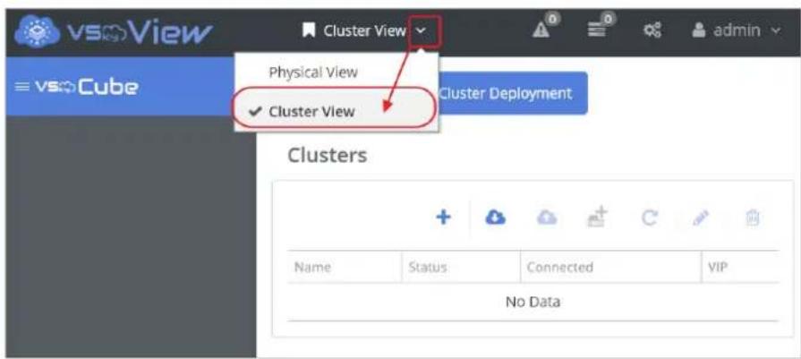
- Switch to Cluster View. The Cluster View window shows all deployed clusters. When signing in for the rst me, this page is empty.
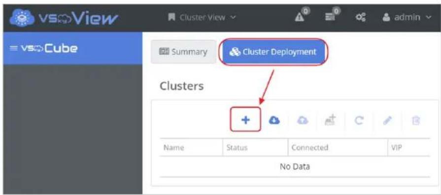
- Switch to the Cluster Deployment tab and click the + icon to deploy a new cluster.
Step 1: Cluster Sengs
Enter the following informaon in the Create Cluster-Cluster Setngs window.
- Cluster Name: A name for the cluster. In this example, it is "demoCluster".
- Virtual IP: Assign an IP to this cluster. This Virtual IP (VIP) represents the cluster and all nodes in the cluster. It will be used for HA (High Availability) sengs in the future.
- Password: Assign a password for the cluster. Keep the password safe, it will be used when 4.4.1 Register Cluster.
-
Time Zone: The region and city where the cluster is located (for example, Region: Asia; City: Taipei).
-
Default Gateway: The IP address of the gateway in the physical network.
• NTP Address: The IP address of the NTP server. This is used for me synchronizaon.
• DNS Servers: The IP address of the DNS server in the physical network.

Step 2: Select Hosts
Select the hosts to be added to the cluster from the drop-down menu. Hosts added in previous steps will be shown here. You can select one host, mulple hosts, or Select All hosts from dierent sites.
Aer selecng the hosts, enter the following informaon for each host, and click Next to connue.
- Management Network Interface: The IP address shown here is the one originally auto-assigned by DHCP. In this step, VSkyCube will automatically turn it into a stac IP. It's highly recommended to change it to a dierent stac IP that is not within the dynamic IP range denied by the DHCP server to the node, otherwise you can modify the dynamic IP range on the DHCP server to avoid IP conicts.

Step 3: Preview and Start Deploying the Cluster
Preview the settings of the cluster. Click Previous to go back to edit or Submit to start deploying the cluster.
![Create Cluster - Preview Step 1 Cluster Settings Select Hosts Step 2 Preview Step 3 Name Virtual IP password Time Zone demoCluster 10.90.6.167 ***************** Asia / Taipei Default Gateway NTP Address DNS Servers 10.90.6.254 10.90.0.93 ["8.8.8.8"] Selected Hosts Network IP Mask Format Disks 1 Management Network Interfaces 10.90.6.166 255.255.255.0 True Cancel < Previous ✓ Submit](/content/2026/06/1199685/images/1c6d0247a3a93684726124619fd75750d98b648de5f121a048036ab8262d9a0f.jpg)
Aer clicking Submit, it will take 30 minutes to an hour to deploy the hosts as the new cluster. It depends on the number of nodes and the hardware performance. During the deployment process, you can check the status in the 4.5.9 Node Deploy Logs. Aer the deployment is complete, the newly deployed cluster appears in the sidebar.

4.2. Trouble Shoong
Q1. The node status shows Timeout during deployment.
The Timeout may have been caused by:
(1) Poor or unstable network communicaons.
(2) A hardware error with too many retries.
(3) Slower than expected disk formang.
To solve this, please follow these steps.
(1) Log in to the node and check the network conneccon between the nodes and VSkyView. (Note: The IP of the node may change during the deployment process. Make sure you use the correct IP address for remote log-in.)
(2) Wait unl the node completes the boot up or disk formang process.
(3) Go back to VSkyView and retry the cluster/node. See 4.4.4 Retry Failed Hosts or 4.5.3 Retry Failed Host.
Q2. A warning message shows up at boong me; what should I do?
This is what you should do if the aached error message shows up at boong me aer a VSkyCube appliance power outage.
The battery hardware is missing or malfunctioning, or the battery is unplugged, or the battery could be fully discharged. If you continue to boot the system, the battery-backed cache will not function.
If battery is connected and has been allowed to charge for 30 minutes
And this message continues to appear, then contact technical support for assistance.
Press 'D' to disable this warning message (If you controller does not have a battery).
FW package: 23.33.0-0025
Memory/battery problems were detected.
The adapter has recovered, but cached data was lost.
Press any key to continue, or 'C' to load the configuration utility.
-
This warning message indicates the VSkyCube appliance was not shutdown properly or there was a power outage before the system nished reboong. So, please just press the 'D' key on the keyboard to disable this warning message and the system will connue reboong.
4.3. Two Network Segment Interface Setng
If you want to gain more eciency by separating management from service, then both management and service network interface sengs are required.
- Management Network Interface: Network for VSkyCube management purposes, primarily through the administrator portal, VSkyView. On the physical interface, make sure to select the eth0 for the management network interface.
- Service Network Interface: Network for VSkyCube provided services accessed by clients outside of the data center.
The management network is for VSkyView portal management, the network trac is lower than the service network interface. Using a 1 Gbps interface card is normally sucient.
The service network provides services access, the network loading is higher, and normally a 10 Gbps interface card is used.
The procedure for creang clusters for two network segments is similar to 4.1 Create a Cluster, except the service network interface should be set.
![Create Cluster - Preview Step 1 Cluster Settings Select Nodes Step 2 Preview Step 3 Cluster Settings Name Virtual IP Default Gateway Time Zone NTP Address DNS Servers Sample 172.16.0.205 172.16.0.1 Asia / Taipei time1.google.com ["8.8.8.8"] Selected Nodes Network IP Mask 1 Management Network Interface 172.16.0.205 255.255.255.0 Sevice Network Interface 172.16.1.205 255.255.255.0 Cancel < Previous ✓ Submit](/content/2026/06/1199685/images/7cfeda0e49436031102597337c08f621a3df47515de1efa248dbc5a59b4bbb0c.jpg)
In addition, here are two reminders for seng the network conguraon.
- The Virtual IP should be lled out with the same network segment as the service network interface.
- The Default Gateway should be lled out with the same network segment as the service network interface.

4.4. Cluster Management
Switch to Cluster View and click the VSkyCube logo on the le sidebar. Select Cluster Deployment tab and the table of clusters will be shown.
The acon buons of cluster are listed above the table of the clusters. Buons from le to right are: (A) Create Cluster, (B) Register Cluster, (C) Unregister Cluster, (D) Add Hosts to the Cluster, (E) Retry Failed Hosts, (F) Edit Cluster, (G) Change Cluster Password, (H) Delete Cluster, (J) Reboot All Nodes and (K) Shut Down All Nodes as shown in the picture below. The details of the acons are introduced in this chapter.

4.4.1. Register Cluster
The Register Cluster opon allows you to register a cluster which is already deployed into VSkyView. Virtual IP and Cluster Password are set when the cluster is deployed. If you forget the VIP or password, see 4.6 Cluster Node CLI for more informaon.

4.4.2. Unregister Cluster
The Unregister Cluster opon allows you to unregister a deployed cluster from VSkyView. Aer the unregistraon, VSkyView and the cluster are disconnected and you are no longer able to access the cluster from the VSkyView. However, all the conguraons and instances running on the cluster will not be eected by the unregistraon. None of the services running on the instance will be interrupted.
Memorize the VIP of the cluster before unregistraon. Then, you can register the cluster back into the same VSkyView or another VSkyView later with the same VIP.

4.4.3. Add Hosts to the Selected Cluster
The Add Hosts to the Cluster opon allows you to add a host which is not yet deployed to an exisng cluster. Follow these steps.
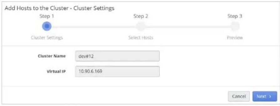
- When you click the Add Hosts to the Cluster buon, there are 3 steps listed in the panel. The rst step is to review the cluster sengs. Make sure the cluster informaon is correct, and then click Next.
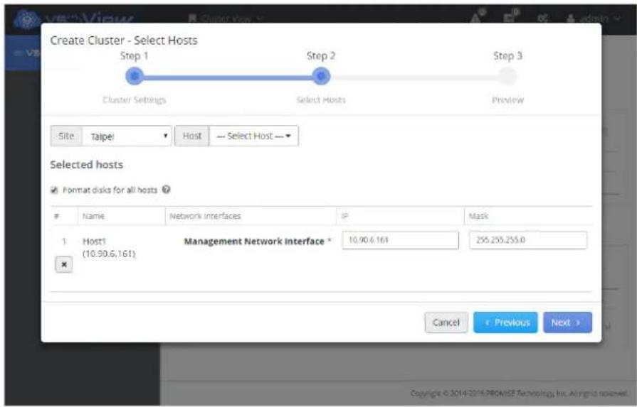
- Step 2. Select Hosts. Select hosts from the dropdown lists Site and Host. Fill in the IP sengs of the hosts to be added. See 4.1 Create a Cluster for more informaon.
- Step 3. Preview. Check if the informaon you entered is correct. If yes, click Submit and the process will start immediately.
Note
New nodes can be added to a cluster any me aer the OS has been installed and connected to the network on the same subnet as the cluster. You can expand the scale of the cluster on demand.
4.4.4. Retry Failed Hosts
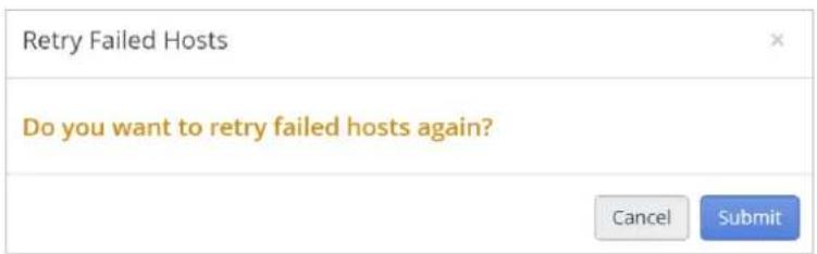
The Retry Failed Hosts opon allows you to retry adding hosts to the cluster aer there is a failure in deployment. However, the system will use the same sengs to retry. If the failure is caused by incorrect cluster or network sengs, the retry won't work. In this case, delete the failed cluster or hosts and try to deploy the cluster or add the hosts again.
4.4.5. Edit Cluster
The Edit Cluster opon allows you to edit the exisng cluster informaon: cluster name and virtual IP.
NOTICE
Changing the virtual IP will cause the cluster to reboot immediately and all the services will be stopped during the process.

4.4.6. Change Cluster Password
This opon allows you to change the password of the cluster. If you forget the old password, see 4.6 Cluster Node CLI for more informaon.
4.4.7. Delete Cluster
This command allows you to delete the exisng cluster. All the nodes will be reset to the manufacturing default sengs.

4.4.8. Reboot All Nodes
It is recommended to use this if the whole cluster needs to be rebooted and there are Controllers and Workers in the cluster. This opon will automatically reboot the nodes in the proper order.
4.4.9. Shut Down All Nodes
It is recommended to use this if the whole cluster needs to be shut down and there are Controllers and Workers in the cluster. This opon will automatically shut down the nodes in the proper order.
4.5. Node Management
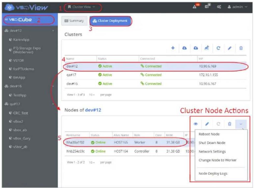
Follow the steps outlined in the picture below. Aer the selecon of the cluster, all nodes of the selected cluster will be shown in the table. Select a node to perform acons.
The node acon buons are listed above the table of nodes. Buons from le to right are: Detail, Edit Node, Retry Failed Host, Delete Node, Network Sengs, Reboot Node, Shut Down Node, Change Node to Controller/Worker, and Node Deploy Logs. The details of the acons are introduced in this chapter.
4.5.1. Node Details
The Node Details panel will display the node informaon like hardware conguraon, OS, and network sengs.
4.5.2. Edit Node
The Edit Node opon allows you to edit the Alias Name of the selected node.

4.5.3. Retry Failed Host
The Retry Failed Hosts opon allows you to retry adding hosts to the cluster aer there is a failure in deployment. However, the system will use the same sengs to retry. If the failure is caused by incorrect cluster or network sengs, the retry won't work. In this case, delete the cluster or failed hosts and try to deploy the cluster or add the hosts again.

4.5.4. Delete Node
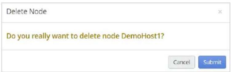
The Delete Node opon allows you to get rid of an exisng node. All the data in the node will be erased. The node will automatically reboot a few mes in the process. When it is nished, all the sengs of the node are reset to the status it was when shipped.
NOTICE
The instances running on the node and the volume stores on the node will all be deleted aer the deleon. To avoid lost data and instance failure, it is recommended to migrate or stop the instances before deleon.
4.5.5. Network Sengs
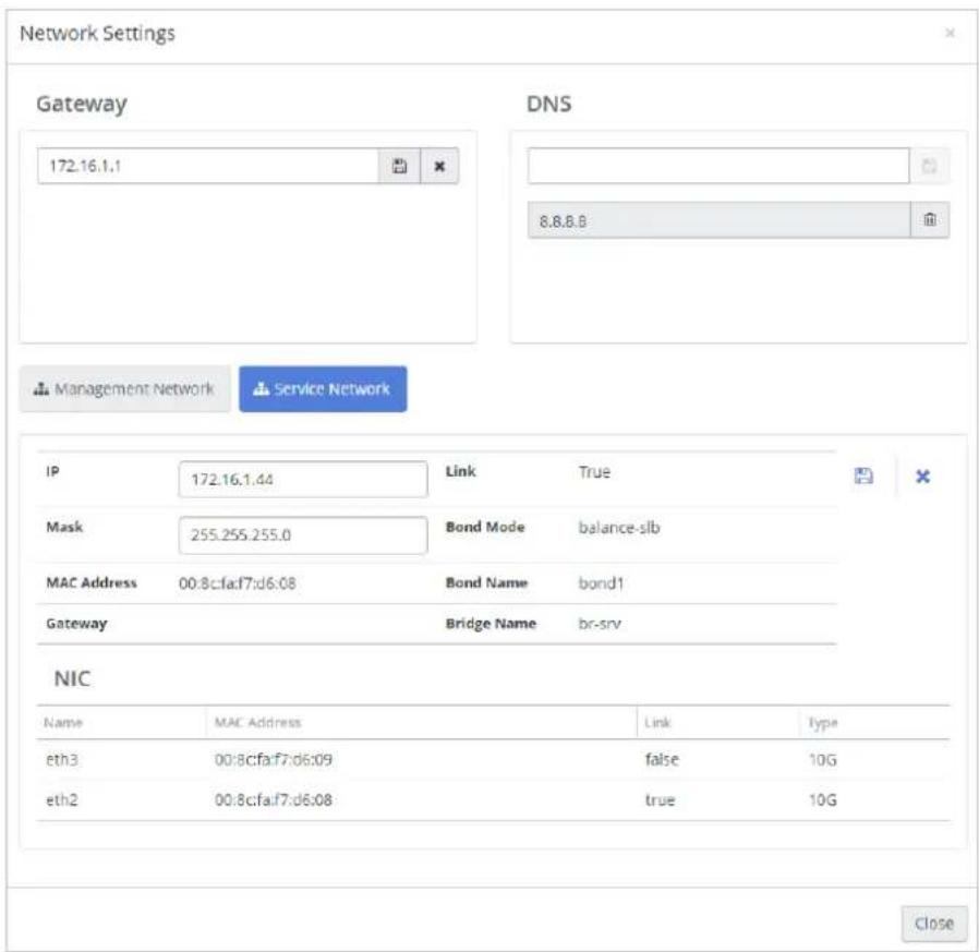
The Network Sengs opon allows you to reset the network sengs for the node. For instance, you can edit the gateway IP address, DNS sengs, management and service network interrelated sengs. All the changes will be applied immediately. The node will reboot a few mes during the process.
NOTICE
Make sure the changes are correct before saving. Incorrect network sengs may cause a failure of the node and the cluster may lose control of the node.
4.5.6. Reboot Node
The Reboot Node opon allows you to restart the node. All the services and instances related to this node will be interrupted during the process of reboot. The services and instances will be started automatically aer the reboot is nished.

4.5.7. Shut Down Node
Click to shut down the node. All the instances running on the node will be stopped together with the node. Migrate the instances before shung down if you want them to connue to operate.
4.5.8. Change Node to Controller/Change Node to Worker
There are 3 possible roles for nodes: Controller, VIP Controller and Worker.
A Controller is the node that receives requests from users and dispatches jobs to each node of the cluster. There should be at least one controller in the cluster. If the cluster has only 1 node, then the node will be a controller.
A VIP Controller is the controller who owns the VIP. VIP Controller is the major of the controllers in the scenario of mulple controllers.
A Worker is the node that receives jobs assigned from the controller. If the cluster contains 2 nodes, then there would be 1 controller node and 1 worker node. If the cluster contains more than three nodes, you can assign two or more nodes as controllers to enable the high availability (HA) mechanism of the cluster. In this case, you need to assign an extra IP as an arbiter IP.
Arbiter IP is a special IP and will be used for the HA mechanism. You will be asked to assign the address of arbiter IP the rst me you change a node to controller. Once an arbiter IP has been assigned, the system will use it as the default arbiter IP sengs even when HA is disabled. Therefore, you don't have to designate an arbiter IP again when re-enabling HA. To change arbiter IP, see the Cluster HA secon in 4.7 Cluster Services.
| Scenario | HA supported | VIP Required | Arbiter IP Required | |
| 1 Node | 1 Controller Node | No | Yes | No |
| 2 Nodes | 1 Controller Node, 1 Worker Node | No | Yes | No |
| 3 Nodes | 1 Controller Node,2 Worker Nodes | No | Yes | No |
| 3 Nodes | 2 Controller Nodes,1 Worker Node | Yes | Yes | Yes |

Troubleshoong
Q3. Image Storage cannot tolerance node failure? When changing a worker node to a controller, an error message popped up. What does this mean?
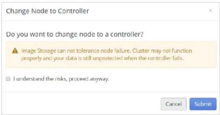
This is about protecon for the system data. By default, Image Storage (image related system data) uses a local disk for storing. This means the data will be lost if the controller fails. Therefore, fault tolerance is required to protect the system data. See 8.2.1.1 Create a RAIN Datastore for Image Storage (Cluster HA) for more informaon. You can sll change the node to a controller, however the probability exists that the cluster may not funcon properly if the controller fails.
4.5.9. Node Deploy Logs
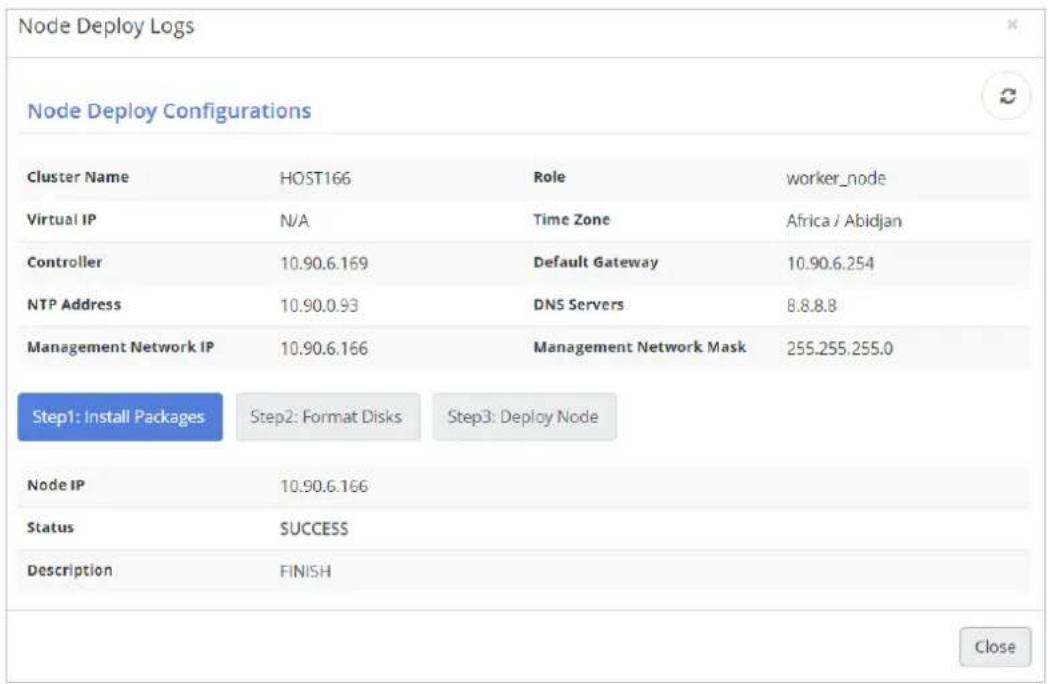
This feature oers the conguraon and status of the deployment process.
Note
The conguraon is updated only when deploying the cluster. All changes aer deployment will not be recorded in the deployment log. Therefore, the conguraon log may be dierent from the current status.
There are 3 steps for the deployment process.
• Install Packages: Install the required libraries.
• Format Disks: Format disks for virtualizaon.
- Deploy Node: Congure and deploy the node.
Troubleshoong
Q4. The deploy process failed at the deploy_service_cong step.
The default mulcast address assigned to each VSkyCube controller is 226.94.1.1 and the port is 50021. If there is another service using the same mulcast address and port, the deployment will fail and stop at the deploy_service_cong step. Also, another VSkyCube cluster in the same subnet will cause the same error. Please check your network environment and then click Retry Failed Cluster/Node to try again.

4.6. Cluster Node CLI Tool
Aer deployment, a Cluster Node CLI is oered when you login to the physical machines. Cluster Node CLI is a command line tool for users and it oers limited commands for safety. For root authorizaon of the node, please contact your VSkyCube/VSkyView administrator.
Note
- It is recommended to use VSkyView to perform acons including shutdown, reboot, and changing network sengs. Acons not performed via VSkyView will be regarded as an unplanned acon and the cluster HA mechanism will be triggered.
- Use the CLI tool only when the node is in failure or abnormal status and cannot be controlled from VSkyView.
- Changing hostname aer cluster deployment is not allowed.
The default account/password for the node is promise / promisepromise Aer login, type 'help' to get the commands list.
| login as: promise promise@10.55.66.133's password: ********** VSkyCube(controller): help | ||
| Command | Usage | Description |
| help | help | Help menu |
| version | version | Show VSkyCube version |
| reboot | reboot | Reboot this VSkyCube appliance |
| shutdown | shutdown | Shutdown this VSkyCube appliance |
| reset_node | reset_node | Reset this VSkyCube appliance back to manufacturer default |
| password | password <New PW> | Change default "promise" user password |
| cluster_password | cluster_password <New PW> | Change VSkyCube admin cluster password |
| ifconfig | ifconfig | Collect network information |
| show_br | show_br | Show network bridge information |
| set_ip | set_ip <BRIDGE> <IP> <MASK> | Set network bridge IP |
| set_dns | set_dns <DNS1,DNS2,...> | Set DNS IPs. Ex: 8.8.8.8,192.168.202.112 |
| set_gw | set_gw <IP> | Set network default gateway |
| vip_transfer | vip_transfer | Force to transfer Virtual IP to current node |
| reboot_status | reboot_status | Show reboot status |
| collect_log | collect_log | Collect VSkyCube logs |
| top | top | Show top information |
| htop | htop | Show htop information |
| df | df | Show df information |
| exit | exit | Exit VSkyCube console |
All the commands are listed below:
| help | help |
| Help menu. Show command list. | |
| version | version |
| Show VSkyCube version. | |
| reboot | reboot |
| Reboot current node. | |
| shutdown | shutdown |
| Shut down current node. | |
| reset_node | reset_node |
| Reset the current node back to manufacturer default. | |
| password | Password |
| Change account promise password. | |
| cluster_password | cluster_password |
| Change password of the cluster. The password is set when deploying the cluster. VSkyView uses the password to access VSkyCube. | |
| Note | |
| Changing the cluster password with CLI will cause VSkyView to lose the authencaon of the cluster. Please unregister the cluster before | |
| changing the cluster password in case of failure, and then register the cluster again with the new cluster password. It is recommended to perform the acon from VSkyView. (See 4.4.6 Change Cluster Password) | |
| ifcong | ifconfigShow network informaon of the node. |
| show_br | show_brShow network bridge informaon of the node, and the VIP informaon of the cluster. |
| set_ip | set_ip |
| Set network bridge IP of the node. Read 4.6.1 Warning for Changing Node Network Sengs before execung this command. | |
| set_dns | set_dnsSet DNS of the node. Read 4.6.1 Warning for Changing Node Network Sengs before execute the command. |
| set_gw | set_gwSet the gateway IP of the node. Read 4.6.1 Warning for Changing Node Network Sengs before execung this command. |
| vip_transfer | vip_transferForce transfer Virtual IP to current node. Read 4.6.2 Transfer VIP via Node CLI before execung this command. |
| reboot_status | reboot_statusShow reboot status. Aer the machine booted up, it needs some me for the node to set up and synchronize the conguraons with other nodes. |
| collect_log | set_dnsCollect the VSkyCube cluster logs and store them on the aached device. |
| NoteThe node should be a Controller node. (See 4.5.8 Change Node to Controller/Change Node to Worker)An USB disk should be plugged into the node.The USB disk should at least contain 1 paron and the logs will be | |
| saved to the rst paron. | |
| top | top |
| Show top informaon. | |
| htop | htop |
| Show htop informaon. | |
| df | df |
| Show df informaon. | |
| remove_isolate | remove_isolate |
| This command appears only when the node is in aQuaranne status. Execute the command to remove the node from theQuarannestatus. The node will be rebooted aer execung the command. See 4.6.3 Remove from Isolaon for more informaon. | |
| exit | exit |
| Exit the VSkyCube console. |
4.6.1. Warning for Changing Node Network Setngs
These are commands that change node network settings: set_ip, set_dns, and set_gw.
The expected situaon to use these commands is when the cluster loses control of the node due to incorrect network sengs. You can manually set the network conguraon of the node to make the node rejoin the cluster. If the cluster is sll in control of the node, it is recommended to use VSkyView to perform the acon instead of using the CLI tool.
4.6.2. Transfer VIP via Node CLI
The VIP of the cluster will be transferred to the current node once the command is executed. Execute the command only when an error occurs on the VIP controller and VSkyView fails to connect to the cluster. It is one of the steps of the cluster HA, therefore please follow the correct order of steps in case of failure. See 4.8 Cluster High Availability for more informaon.
4.6.3. Remove from Isolaon
Remove the node from Quaranne. This command only appears when the node is in the Quaranne status. It is one of the steps of the cluster HA recovery, therefore please follow the correct order of the recovery steps in case of failure. See 4.8 Cluster High Availability for more informaon.

FAQ
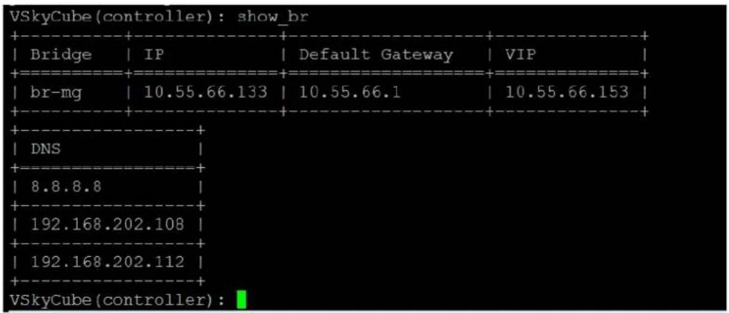
Q5. What command should I use to see the cluster VIP informaon?
Use command show_br to get VIP informaon.
4.7. Cluster Services
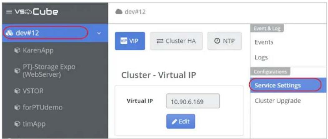
The informaon in this secon explains the cluster service funcons. Select a cluster from the le sidebar and select Service Sengs under Conguraon in the Cluster-Related menu.
4.7.1. Cluster Service Sengs
The Service Sengs opon provides cluster-related sengs. You will be required to provide informaon regarding the VIP (virtual IP), Cluster HA, NTP, Time Zone, and Data Expiraon.
- Virtual IP: Allows you to edit the virtual IP. The network service will restart automacally aer eding.
- Cluster HA: Allows you to change the arbiter IP of cluster HA. See 4.5.8 Change Node to Controller/Change Node to Worker.
• NTP: Allows you to edit the NTP server.
• Time Zone: Allows you to edit the Time Zone sengs.
• Data Expiraon: Allows you to change the monitor and log data expiraon.


4.8. Cluster High Availability
The possible roles for nodes are: VIP Controller, Controller, and Worker. (See 4.5.8 Change Node to Controller/Change Node to Worker for more informaon.) The cluster HA has dierent behavior for each role. In this chapter we will introduce the behavior of the roles respectively when the cluster High Availability is enabled. Also, the behavior of virtual machines (instances) running on the nodes while cluster HA happens will be introduced.
4.8.1. Cluster High Availability Requirements
-
Two or more acve Controllers.
-
The performance of the datastore for Image Storage should be higher than regular, or the RAIN mechanism should be enabled.
4.8.2. Cluster High Availability Scenarios
Note
Please perform shutdown/reboot node with VSkyView. Acons not through VSkyView will be regarded as unplanned acons and the cluster HA mechanism will be triggered.
Node Role: VIP Controller
- Planned Shutdown/Reboot (Shutdown/Reboot VIP Controller with VSkyView)
VIP is automacally transferred to another controller. If there is no other controller, then the cluster funcon won't work. Instances auto migraon will be triggered aer VIP is transferred. Instances running on other nodes won't be aected. - Unplanned Shutdown/Reboot (Shutdown/Reboot VIP Controller not with VSkyView, network disconnected, or unexpected errors)
The cluster funcon won't work until the VIP is successfully transferred. The VIP transfer needs to be triggered manually by the user. Instances running on the other node won't be acted.
Node Role: Controller, Worker
- Planned Shutdown/Reboot (Shutdown/Reboot the node with VSkyView)
Instance auto migraon will be triggered. Instances running on other nodes won't be aected. - Unplanned Shutdown/Reboot (Shutdown/Reboot the node not with VSkyView, network disconnected, or unexpected errors)
Instances auto migraon will be triggered. Instances running on other nodes won't be elected.
4.8.3. Workow of High Availability and Recovery (VIP Controller)
The table below describes the Controller HA workow and the steps for recovery from an unexpected error. Some acons need to be performed with the CLI tool. See 4.6 Cluster Node CLI Tool for more informaon.
| Step 0↓ | When an error occurs on a VIP Controller (Controller and the VIP owner), the cluster status will bedisconnectedon VSkyView and you are unable to perform any acons on VSkyView.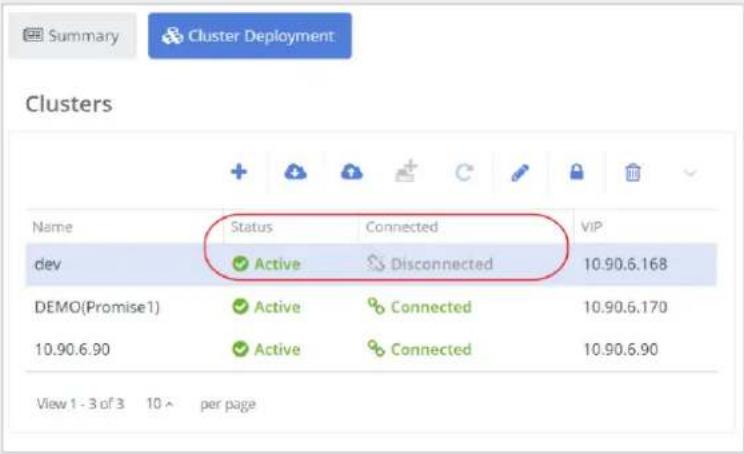 |
| Step 1↓ | Shutdown and isolate the abnormal node from the cluster if possible. |
| Step 2↓ | All of the other acve controllers will reboot automacally and try to transfer VIP while the cluster lost the VIP Controller. Login to one of the controller and use CLI toolreboot_statusto check the reboot status. The reboot status will stooped atget_node_info_from_controller. All acve controllers will stop at the same step. |
| Step 3↓↓ | Execute command vip_transfer via node CLI tool. VIP of the cluster will be transferred to the node where the command vip_transfer is executed and the node will reboot immediately. |
| Step 4↓↓ | Aer VIP transfer, the reboot status of all the controllers should successfully complete. You can execute reboot_status to check. The cluster funcons are working properly and the instance auto migraon for the VIP Controller is triggered automacally in this step. |
| Step 5↓↓ | The cluster status back to acve on VSkyView. The status of the abnormal node is marked asQuaranneon the table of cluster nodes. |
| Step 6↓↓ | Fix the errors of the abnormal node. If error xed, go next step to re-join the node into the cluster. Or go to step 9 to force delete and reset the node. |
| Step 7↓↓ | Login to the xed node, and execute command remove_isolate via node CLI tool. The node will be reboot aer execute the command. |

| Step 8 | The node status should back to acve aer reboot. Now the recovery process is completed. |
| Step 9↓ | Execute Delete Node acon via VSkyView. A warning message pops up to nofy user the abnormal status. Check ‘Force Delete’ to force delete the node. The node will reboot and reset back to manufacturer default aer execute the delete. The host informaon of the node will also be removed from VSkyView. NoteAer delete, all the instances and data stores on the node will also be deleted. This acon cannot be reversed. It is recommended to back up the data and the instances running on the selected node before delete. NoteAer delete, all the instances and data stores on the node will also be deleted. This acon cannot be reversed. It is recommended to back up the data and the instances running on the selected node before delete. |
| Step 10 | Wait unl the node boot up. The default IP address of the node will be fetched from DHCP aer reboot. Login to the node with default account and get the new IP address of the node. Then add the host into VSkyView as a new. See Chapter 3. Host Management for more informaon. |
4.8.4. Workow of High Availability and Recovery (Controller and Worker)
The table below describes the Controller HA workow and the steps for recovery from an unexpected error. Some acons need to be performed with CLI tool. See 4.6 Cluster Node CLI Tool for more informaon.
| Step 0↓↓ | When an error occurs on a Controller (not VIP owner) or Worker node, the cluster funcon will not be eected and the status of the cluster will remainAcve. The instance auto migraon for the error node is triggered automacally. |
| Step 1↓↓ | The status of the abnormal node will beOineon the table of cluster nodes. |
| Step 2↓↓ | Fix the errors of the abnormal node and follow the next step to re-join the node into the cluster, or go step 5 to force deleon and reset. |
| Step 3↓↓ | Reboot the node aer the error is xed, and then the node will try to join the cluster again automacally. It takes about 5~10 minutes to synchronize the data. During the synchronizaon process, the status of the node will remainOfineeven if the node has power-on. |
| Step 4 | The status of the node will be back toOnlineaer the synchronizaon process. Now the recovery process is complete. |
| Step 5↓↓ | ExecuteDelete Nodeacon through VSkyView. A warning message pops up to nofy user the abnormal status. Check ‘Force Delete’ to forcibly delete the node. The node will reboot and reset to the manufacturer defaults aer execute the deleng. The host informaon of the node will also be removed from VSkyView. NoteAer deleng, all the instances and data stores on the node will also be deleted. This acon cannot be reversed. It is recommended to back up the data and the instances running on the selected node before deleng. NoteAer deleng, all the instances and data stores on the node will also be deleted. This acon cannot be reversed. It is recommended to back up the data and the instances running on the selected node before deleng. |
| Step 6 | Wait unl the node boot up. The default IP address of the node will be fetched from the DHCP server aer reboot. Login to the node with the default account and get the new IP address of the node. Then add the host into VSkyView as new. See Chapter 3. Host Management for more informaon. |
4.9. Event and Log
Select a cluster from le sidebar and select Events or Logs under Event & Log on the Cluster-Related menu.

The Events opon provides informaon regarding the plaorm. The event records are categorized in three different levels: Events, Alerts, and Tasks. You can audit the cluster progress or situation with these event records.
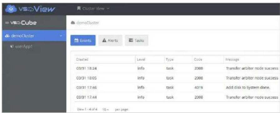
The Log opon provides log-related informaon. You can query or download specic log informaon by ltering given criteria. For example, seng a given host, me interval, log level, or log number limit.

4.9.1. Email Nocaon
To get the email nocaon of events and alerts, please set up the conguraon of SMTP mail server and enable the nocaon. See 2.3 VSkyView System Sengs for more informaon.
5. Chapter 5. Applicaon Management
Use the informaon in this secon for applicaon management.
5.1. Create an Applicaon
An applicaon is a service project, for example, a le sharing applicaon or a mail server applicaon. Each applicaon has a given quota of resources in the VSkyCube cluster. This is the way VSkyCube manages the resource allocaon and usage by dierent services.
This secon will show you how to create an applicaon in VSkyCube.
- To create an applicaon, select a cluster from the le sidebar, click Conguraons under Applicaon on the right side menu, and click the icon.
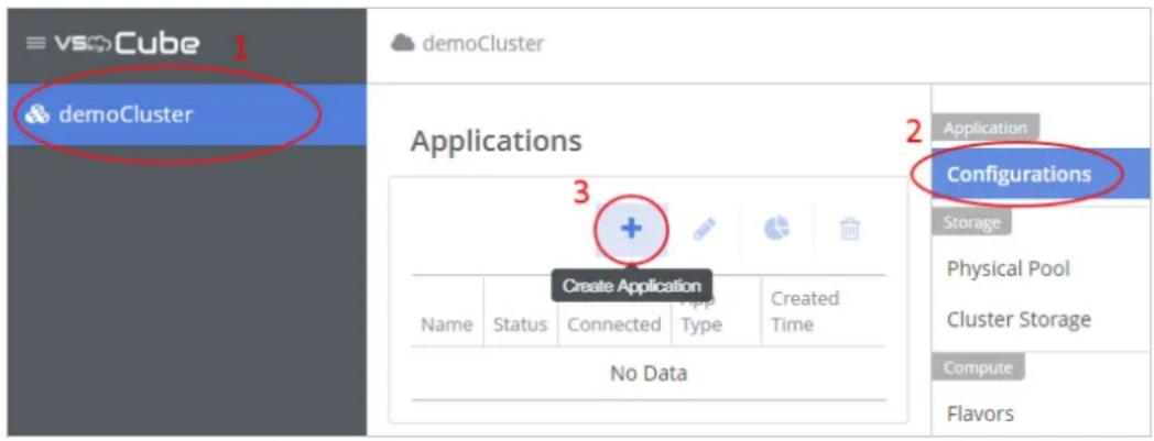
- The Create Applicaon window appears. Enter the applicaon name and select the applicaon type. Applicaon type names starng with VSky, such as VSkyStor, VSkyBox, and VSkyPoint, are provided by Promise and especially designed and optimized to run on VSkyCube. In general, select User dened app.

- Click Submit. The newly created applicaon will appear under the cluster on the le sidebar.

5.2. Applicaon Wizard
Applicaon wizard will guide you to build VSky series services. Go to Applicaons and click the magic wand buon to open the wizard and then follow the steps.


Exing the Applicaon Wizard
There are two ways to exit the Applicaon Wizard. Quit Wizard and Force Quit.
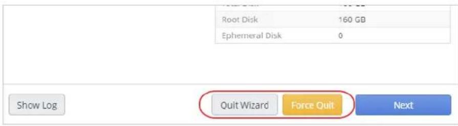
If you click the Quit Wizard button, a warning message will prompt you to make sure that is what you want to do.
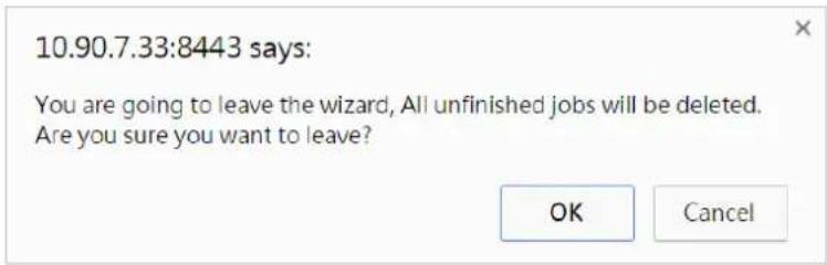
Every me you run the applicaon wizard, an applicaon will be created. Quing the wizard and conming the message will delete the applicaon. If you are an advanced user, you can click the Force Quit buon to leave the wizard without deleng the applicaon. A warning message will again prompt you to conrm your decision and save the unnished jobs. Then, you can connue the unnished jobs manually.
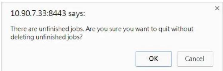
Note
The delete applicaon process takes about 10 minutes. The resources are blocked during this me. Therefore, it is recommended to wait unl the applicaon is completely deleted to avoid resource shortages.
5.3. Applicaon Acons
There are 4 applicaon acons that can be performed: Create Applicaon, Edit Applicaon, Edit Applicaon Quotas, and Delete Applicaon.
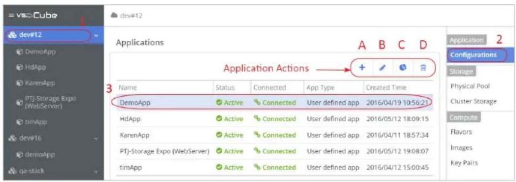
- Select the cluster listed in the le side bar.
- Click Conguraons on the right menu.
- Click on the row to select an applicaon.
The applicaon acons are listed on top of the table:
- Click the plus buon to create a new applicaon.

- Click the pencil icon 🔍 to edit the name of the selected applicaon.

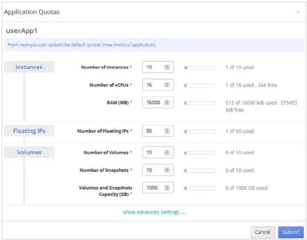
- Click the pie chart icon ⬆ to edit the resource quotas of the selected applicaon.
- Click the trashcan icon tdelete the selected applicaon.

6. Chapter 6. Virtual Machine Management
An instance is another name for a virtual machine. You can create your own instances under certain applicaons.
6.1. Launch an Instance
Below are the minimum steps to launch an instance.
- Instance Detail: Dene basic specicaons including name, CPU, and memory for the instance.
- Access & Security: Specify the SSH key pair to access the instance, and select Security Group, the rewall sengs of the instance.
• Networking: Specify the internal network subnet for the instance.

flowchart
graph LR
    A["Launch Instance"] --> B["Instance Detail"]
    B --> C["Access & Security"]
    C --> D["Networking"]
    D --> E["Submit!"]
    B --> F["Select Flavor"]
    B --> G["Select Image"]
    C --> H["Set Key Pair"]
    C --> I["Add Security Groups"]
    D --> J["Select Networks"]
Before you can launch an instance, you need to:
- Set up the internal network for the instance.
See 7.2 Build a Basic Network Environment for more informaon. - Set up the instance boot source.
It can be an image, snapshot, or block storage volume that contains an image or snapshot. For beginners, the use of an image as the boot source is recommended. See 6.5 Images to create an image, and 6.2 Instance Boot Source for more informaon.
• The avor for your instance.
A avor is an available hardware conguraon for an instance. It denes the size of a virtual machine that can be launched. There are ve default avor templates: ny, small, medium, large, and xlarge. To dene your own avor, see 6.6 Flavors.
• (Oponal) A key pair for your instance.
Key pair is SSH credenals injected into images when they are launched. For the key pair to work, the image must contain the cloud-init package. See 6.7 Key Pairs.
- A security group that denies which incoming network trac is forwarded to instances. Security groups hold a set of rewall policies, known as security group rules. See 6.8 Security Groups.
Follow this example to launch an instance.
- To create an instance, select the applicaon on the le sidebar, click Instances under Compute on the right menu, and click the +con in the main window.

-
The Launch Instance window appears. Enter the following informaon.
-
Instance Name: A name for the instance, in this example, myUbuntu.
- Flavor: Flavor is an instance template with predened virtual resources. Select one from the drop-down menu, and the avor details will be shown on the right side, the Flavor Details secon.
• Instance Count: The number of instances to create. - Launch Instance on node: If you want to create the instance on a specific node in the cluster, select the node from the drop-down menu, otherwise use the default seng, Any available node.
- Instance Boot Source: Select where to boot the instance. Boot from image is the open most oen used. If you want to create an instance that supports live migraon, you need to create a bootable volume and launch it from a bootable volume. See 6.2 Instance Boot Source for more informaon.
• Image Name: Select an image from the list.

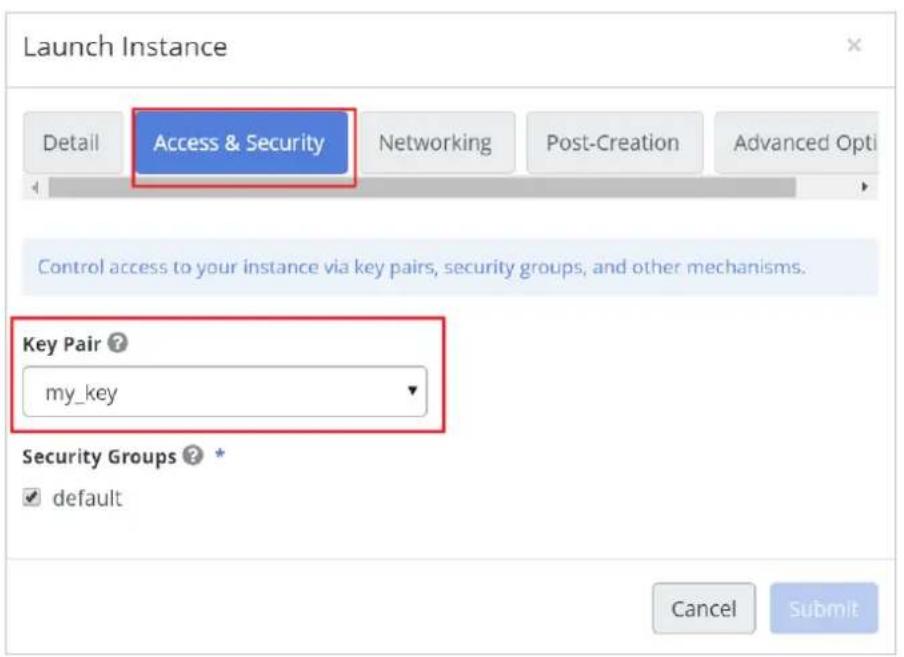
- Switch to the Access & Security tab. Select a key pair from the drop-down menu, in this example, my_key, or select none to disable key pair if the image does not support it. Select the default Security Groups.
- Switch to the Networking tab. Pull down the Available Networks menu and select the subnet of the internal network.

- The next two tabs Post-Creaon and Advanced Opons are oponal advanced sengs. Click Submit to launch the instance.
It takes a few minutes to create the instance. When the instance is ready for use, it will be displayed in the main window with a Status of Acve.

6.2. Instance Boot Source
There are ve different Instance Boot Source opons provide to you to launch instances and will be introduced in this chapter. For beginner, it is recommended to use Boot from Image as the boot source opon. For other opons, you have to be familiar about create image and volume. See 6.5.1 Create Image and 8.5.1 Create Volume.
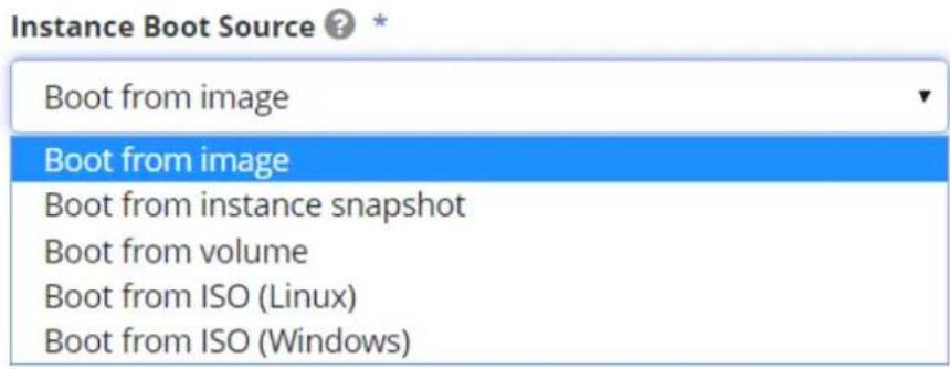
6.2.1. Boot from image
Select the image le for a specific operang system used to create a server. You have to create images rst, and then the images will be listed in the dropdown list. See 6.5.1 Create Image.
NOTICE
An instance launched from an image can do migraon, however the services running on the instance will be paused while migrang. To avoid service interrupon, it is recommended to do live migraon. An instance launched from a volume will be able to do live migraon. See 6.2.3 Boot from volume for more informaon.
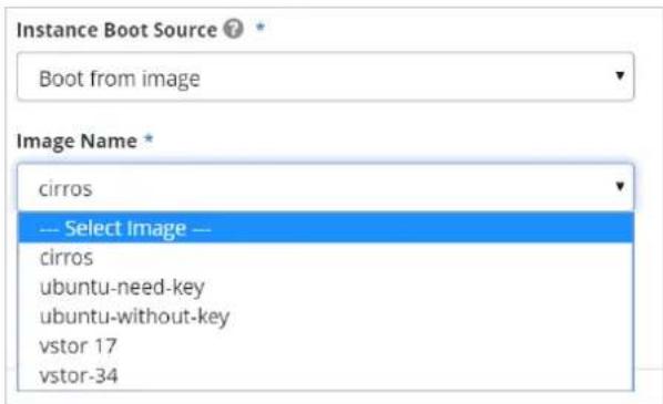
6.2.2. Boot from instance snapshot
An instance snapshot is a point-in-me copy of an image. You can take an instance snapshot to back up a currently running instance. Instance snapshots that have been created will be included in the dropdown list. See 6.3 Instance Acons for more informaon.

6.2.3. Boot from volume
You can select a bootable volume as the instance boot source. You have to create a bootable volume. It will be added to the dropdown list. See 8.5 Volume to create a bootable volume.
NOTICE
An instance launched from a bootable volume will be able to do live migraon.

6.2.4. Boot from ISO (Linux)
To launch an instance from a Linux ISO le, please follow these steps.
- Create the ISO image le. The disk format of the image should be ISO-Opcal Disk Image.
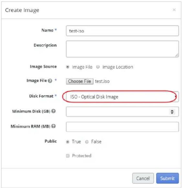
- Create a bootable volume and use the Linux ISO image as the volume source. The size of the volume doesn't maer but needs to be larger than the image.

- Aer then create, the volume will be listed in the table of volumes. Wait until the status of the volume become Acve. Select the volume, and click Launch as Instance buon on top of the table.

- In Launch Instance panel, select the Boot from ISO (Linux) as the boot source, and for OS Volume, choose the volume you created in step 2. Fill out other elds, and submit.

- The instance will be created. Go to Instances service, and wait until the status of the instance becomes Acve.

- Login to the instance, you will see the OS installaon message. Proceed with the installaon process of the OS.

- Aer installing the OS, you can detach the ISO volume. Shut down the instance and wait until the status of the instance becomes Shuto.

- Go to Volumes service, select the ISO volume and click Manage Aachments.

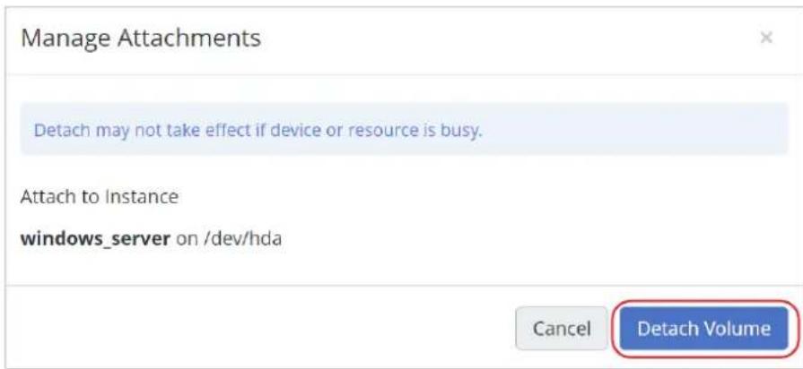
- Click Detach Volume. Then the ISO volume will be detached from the instance. Wait unl the status of the volume becomes Available.

- Aer detaching, the instance and the ISO volume are separated. You can repeat the steps to launch another instance or delete the ISO volume.
6.2.5. Boot from ISO (Windows)
- You need to prepare 2 les in your local folder, one is the ISO le of Windows OS and another is the VirtIO driver that supports windows virtual machine to boot up.
NOTICE
VirtIO is the drivers for Windows virtual machines running on KVM. For more informaon, see hps://fedoraproject.org/wiki/Windows_Viro_Drivers
- Create 2 images, one is for the windows ISO le, and another is for the VirtIO drivers. The disk format of the images should be ISO - Opcal Disk Image.

- Create 2 volumes for the images you created in the previous step. Select the images as the Volume Source respectively. The Size of the volumes should be larger than the size of images.
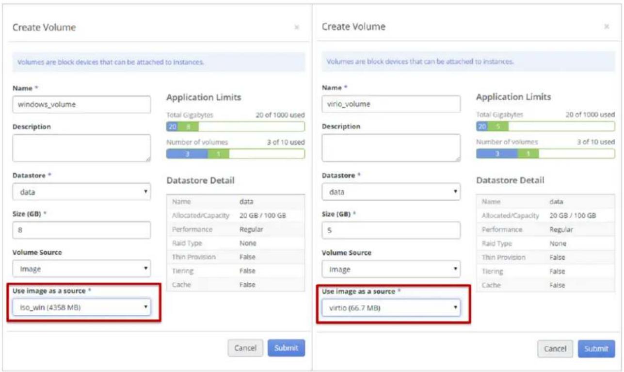
- Go back to the instance boot source menu, select the Boot from ISO (Windows) opon, and there are two opons that need to be chosen. Under OS Volume choose the windows volume and under VirtIO Volume select the VirtIO volume that you just created. Make sure the size of the Root Disk displayed in Flavor Detail is larger enough for the OS of the ISO, or the instance may not be able to be booted. Fill out other elds, and click Submit.

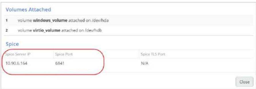
- Wait unl the instance status becomes Acve. Select the instance and click the eye buon on top of the table to see the detail of the instance. There should be two volumes aached to the instance. One is the volume of the windows ISO and the other is the volume of VirtIO driver. At the secon of Spice, the Spice Server IP and Spice Port are listed. Use the IP and port to access the instance with the VSkyConsole. See 6.4 Accessing Instances for more informaon.


- Login the instance via VSkyConsole, you will see the installaon UI of Windows.

- Follow the installaon steps. For Windows Server, choose the Server with a GUI opon.

- Follow the installaon steps, unl the "Where do you want to install Windows?" message opens. The table is supposed to be empty. Click the Load driver opon.

- Conrm the warning message.
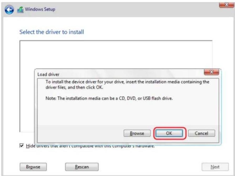
- Click the CD Drive (E:) CD ROM item to expand the tree menu. Select the driver compatible to the OS version of the instance and click OK.
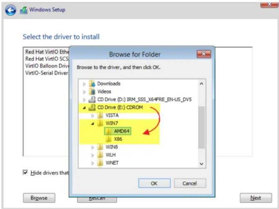
- Select all drivers listed and click Next.

- The root disk will be listed as unallocated disk space. The size of the root disk is specified when launched.

- The root disk will be listed as unallocated disk space. The size of the root disk is specified when launched. Set up the disk size and click Apply.

- Conrm the warning message.

- Select the primary drive and click Format. All the data in the disk drive will be erased aer format.

- Conrm the warning message.

- Aer formang, select the primary disk and click Next to proceed with the installaon.

- Wizard started to set up the OS. Wait unl the installaon nish.

- Now your OS installaon has nished.
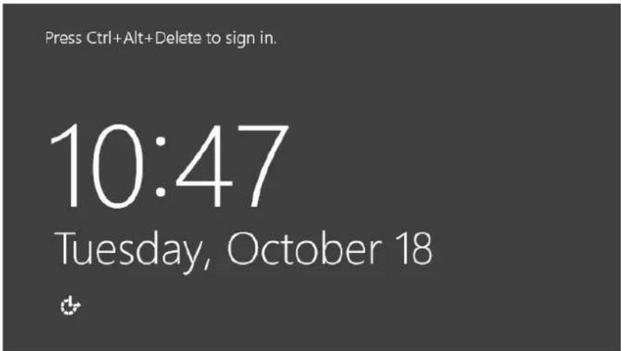
- To detach the ISO volumes, shut down the instance. Wait unl the instance status become Shuto.

- Go to Volumes, select the volume and click the Manage Aachments buon . Click the Detach buon on the pop-up screen. The ISO volumes can be reused or deleted aer detach.

6.3. Instance Acons
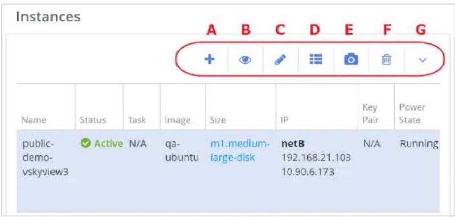
The funcons for instances are listed on top of the table of instances. As shown in the picture above. They are introduced below.
• + Launch Instance: Launch and create an instance.
• Instance Details: View details of the selected instance.
• Edit Instance: Edit the name of the selected instance.
• Edit Metadata: Edit metadata of the selected instance.
Metadata contains the properes of an instance. You can create your own metadata, but metadata created by system cannot be edited.

• Create Instance Snapshot: Take a snapshot of the selected instance.
The snapshot mechanism allows you to create new images from running instances. This is very convenient for upgrading base images or for taking a published image and customizing it for local use.
NOTICE
The snapshot created from an instance booted from an image will be in qcow2 format and will be listed in the table of images. While a snapshot created from an instance booted from a volume will be a volume-snapshot and will be listed in the table of volume snapshots.
A mestamp format posix will be added automacally as the name of the snapshot. You can change it to a meaningful name.

- Delete Instance: Click to delete the instance, this acon will clear all the data of the instance and cannot be undone.
- More: More acons for instances are listed in the table below.
Instance Acons
| So Reboot | A so reboot aempts a graceful shut down and restart of theinstance. |
| Hard Reboot | A hard reboot power cycles the instance. |
| Stop | The instance powers-o and transions to shuto. |
| Pause/Unpause | This command stores the state of the instance in RAM. A paused instance connues to run in a frozen state. Unpause: resume the state of the paused instance. |
| Suspend/Resume | Suspend funcon stores the state of VM on disk.Resume instance from the suspend state. |
| Rescue/Unrescue | If an instance le system becomes corrupted, Rescue mode provides a mechanism for access even when the VM image renders the instance inaccessible.Unrescue: Resume instance from the rescued state. |
| Rebuild | Rebuild an instance from a fresh image while maintaining the same xed and oang IP addresses, amongst other metadata. |
| Resize | The Resize funcon is the ability to change the avor of the instance, thus allowing it to upscale according to your needs. Aer resizing, you need to conrm the change. |
| Migrate | The Migrate funcon allows you to move an instance from one compute node to another. You can assign a specic host to migrate or allow the system to migrate automacally. Aer migrang, you need to conrm the migraon. |
| Live Migrate | Live migraon is the movement of a live instance from one compute node to another. Only used for instances booted from a volume. |
| Associate Fixed IP | Assign a xed IP to the instance. The xed IP is allocated from the internal network of the instance. |
| Disassociate Fixed IP | Remove one of the xed IPs from the instance. |
| Associate Floang IP to Instance | Assign a oang IP to the instance. A oang IP is allocated from the external network of the cluster. You need to create the router connecng the external network and internal network of the instance rst. See 7.2 Build a Basic Network Environment. |
| Disassociate Floang IP to Instance | Remove the oang IP from the instance. |
| Edit Security Group | Change the security group sengs of the instance. Security group is the collecon of rewall policies for the instance. |
| Console Log | Print the console logs of the instance. |
Behaviors
For resizing and migraon acons, you need to conrm in order to apply the changes. Click the down arrow buon and select Conrm Resize/Migrate to conrm and select Revert Resize/Migrate to revert the instance back to previous state.

6.4. Accessing Instances
There are two ways to access instances: with SSH or with VSkyConsole.
Note
VSkyConsole is a VSkyCube ulity. It is used to access instances.
Select the instance and click the eye buon on top of the table to see the detail of the instance.

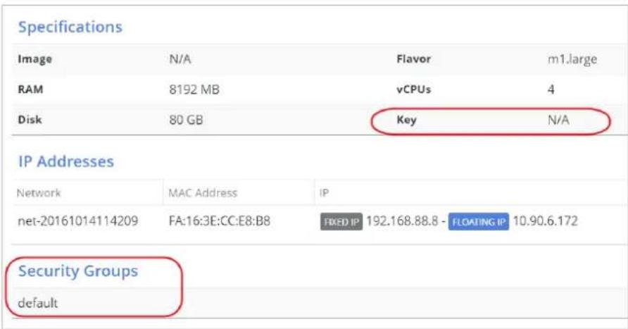
As shown in the picture below, the networks of the instance are listed in the IP Addresses secon. Networks of the instance are specied when launching the instance and are not allowed to be changed.

There are two types of IP: Fixed IP and Floang IP. A xed IP is an IP allocated from the internal network and a oang IP is allocated from the external network. Instances get a xed IP address for each internal network by default. A oang IP is associated to a xed IP. You can add or remove xed IPs and oang IPs aer launching. See 6.3 Instance Acons for more informaon.
One way to access the instance is with SSH and the floang IP. Check the Key eld in the Specicaon secon and the Security Groups secon. Make sure you use the correct SSH key and allow the incoming network packages of SSH to access the instance. See 6.8.2 Set Up Security Group Rules for accessing Instances for more informaon about security group.
Another way to access an instance is through VSkyConsole. At the Spice secon, the Spice Server IP and Spice Port are listed. Use the IP and port to access the instance through VSkyConsole. The Spice server IP and port changed every me the instance boots up.
6.5. Images
An image is a single le containing a virtual disk that includes a bootable operang system. You can create an image for an individual applicaon, or you can create one for a cluster, which will be available to each of its applicaons.

6.5.1. Create Image
Images come in dierent formats. Below are disk formats supported by VSkyCube.

For a quick start, we can use an image with QCOW2, VDI, VHD or VMDK format. Images in these formats follow the steps below. Images with Amazon or ISO formats have dierent steps.
Some images contain a cloud-init package to support SSH key pair, while some images use SSH password authencaon instead. If the image supports SSH key pair, go to the next step to create key pairs aer the image is uploaded.
Prepare the image rst and then follow these steps to upload.
-
Select a cluster or applicaon from the le sidebar. If uploading an image to a cluster, then all applicaons in this cluster can ulize the image.
-
Click Images under Compute on the right menu, and click the + icon.

- The Create Image panel appears. Enter the following informaon and then click Submit to upload the image.
• Name: A name for the image.
- Image Source: Select the image locaon, Image File locally and Image Locaon from the Internet.
• Image File: Select the local image le or enter the HTTP URL.
- Disk Format: Choose the disk format of the image. Here we use QCOW2-QEMU Emulator as example. You need to choose the correct format of the image, or the image may not be able to launch.
• Minimum Disk (GB): The minimum disk size required to boot the image.
• Minimum RAM (MB): The minimum memory size required to boot the image.

6.5.2. Creang an Amazon Machine Image (AMI)
AMI (Amazon Machine Image)
An AMI provides the informaon required to launch an instance, which is a virtual server in the cloud.
AKI (Amazon Kernel Image)
The AKI represents the vmlinuz poron of the kernel. It is basically the compiled kernel that gets loaded on boot.
ARI (Amazon RAMDisk Image)
The ARI represents the initrd/initramfs. This is the RAMDisk that gets loaded with the kernel and has the initial driver modules for the kernel to nd the root lesystem.
With tradional AKIs and ARIs you will also need the corresponding kernel modules installed on the le system. Without these the system will normally not be able to boot. Follow the steps to create an AMI image and the corresponding AKI/ARI images.
- Go to Images, and click the Create buon to open Create Image dialog box.
- Create the AKI image, and make sure the AKI-Amazon Kernel Image opon in Disk Format is selected.

- Create the ARI image, and make sure opon ARI-Amazon Ramdisk Image in Disk Format is selected. If there is no related ARI le for your AMI image, skip this step.
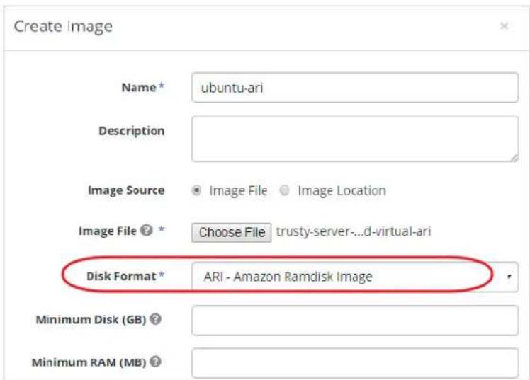
- Create the AMI image, make sure the AMI-Amazon Machine Image opon in Disk Format is selected, and select the appropriate AKI and ARI images in the drop-down menu.
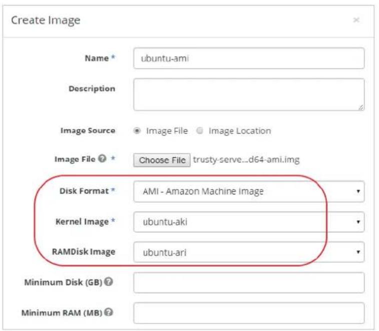
- Now the images are ready The AMI image is able to be launched.
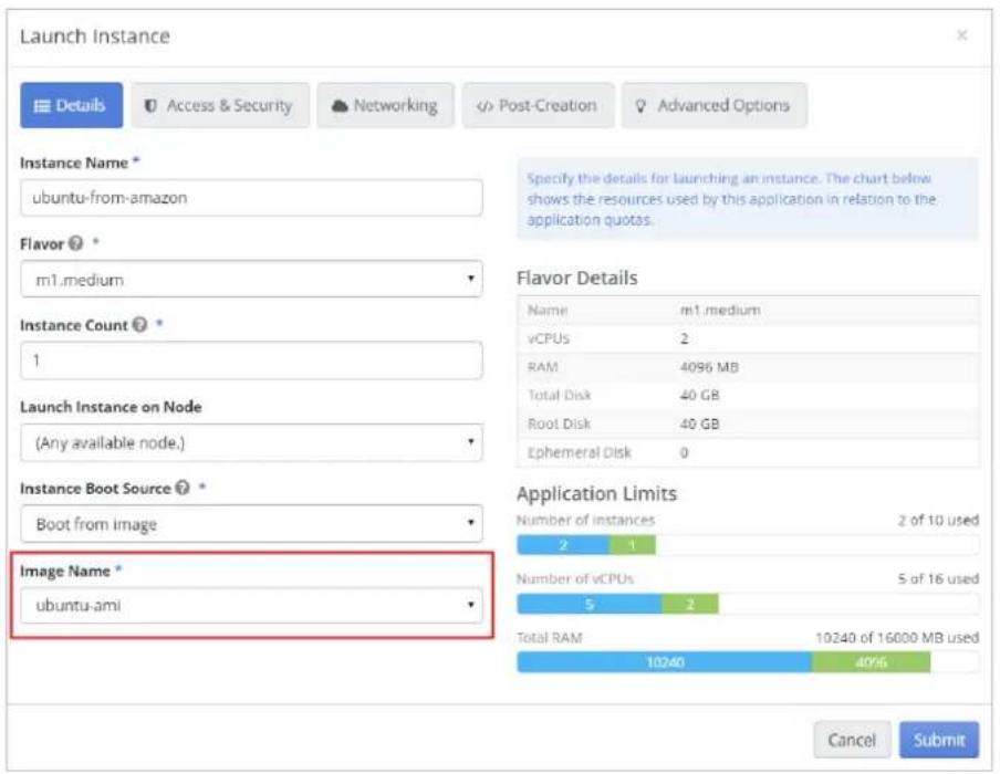
6.5.3. Image Acons

The acons of images are listed on top of the table. As shown in the above picture, acons are introduced below from le to right.
• create Image: Create an image.
• Image Details: View the details of the selected image.
• Edit Image: Edit the properes of selected image.
- Launch as Instance: Launch an instance and use the selected image as the boot source.
• ↑ Create Volume: Create a volume and use the selected image as the volume source.
- Image Tags: Edit the tags of selected image. Tags are the metadata of an image. You can also create your own tags.
• Download Image: Download the selected image.
- Delete Image: Delete the selected image.
Noce
Make sure there are not any instances of other applicaons launched with the image before deleng it.
6.5.4. Image Life Cycle
The picture below describes the image life cycle and the relationship between Image, Instance, and Snapshots. See 6.5.3 Image Acons, 6.3 Instance Acons, and 8.5.5 Volume Acons for more informaon.

flowchart
graph TD
    A["Image"] --> B["Image (Type: Snapshot)"]
    B --> C["Instance (Boot from Image)"]
    C --> D["Volume Snapshot"]
    D --> E["Volume"]
    E --> F["Volume"]

    subgraph Image
        G["(M1) Download Image<br>Download Image File<br>to Client"]
        H["(U1) Upload Image<br>Upload Image File<br>from Client"]
        I["(M2) Create Volume<br>Create Volume from Image"]
        J["(V5) Upload to Image<br>Create Image from Volume"]
        K["(V4) Launch Instance<br>Launch Instance from Volume"]
        L["(I1) Create Snapshot<br>Create a Snapshot of Instance boot from Volume"]
        M["(S1) Upload to Image<br>Create Image from Volume Snapshot"]
        N["(S2) Create Volume<br>Create Volume from Volume Snapshot"]
        O["(V3) Create Snapshot<br>Create Volume Snapshot from Volume"]
        P["(V2) Attach/Detach Volume<br>Attach/Detach Volume to instance as a Virtual Disk"]
        Q["(V1) Create Volume<br>Create a New Volume from an Existing Volume"]
    end

    subgraph Instance
        R["(M2) Create Volume<br>Create Volume from Image"]
        S["(M2)"]
        T["(V5)"]
        U["(V4)"]
        V["(I1)"]
        W["(S1)"]
        X["(S2)"]
        Y["(V3)"]
        Z["(V2)"]
        AA["(I2)"]
        AB["(I1)"]
        AC["(I3)"]
        AD["(I4)"]
        AE["(M4)"]
        AF["(M3)"]
        AG["(I2)"]
    end

    subgraph Volume
        AH["(V1) Create Volume<br>Create a New Volume from an Existing Volume"]
        AI["(V1)"]
        AJ["V1"]
    end

    B -->|M1| B
    B -->|U1| B
    B -->|(M4) Launch Instance
Launch Instance
from Instance Snapshot|
    B -->|M4| B
    B -->|(I2) Create Instance Snapshot
Create a Snapshot of Instance boot from Image|
    B -->|I2| B
    B -->|(I1) Create Snapshot
Create a Snapshot of Instance boot from Volume|
    B -->|S1| B
    B -->|(I3) Launch Instance
Launch Instance from Image|
    B -->|S2| B
    B -->|(I4) Launch Instance
Launch Instance from Image|
    B -->|S3| B
    B -->|(I5) Launch Instance
Launch Instance from Image|
    B -->|V4| B
    B -->|(V5) Upload to Image
Create Image from Volume|
    B -->|(V6) Upload to Image
Create Image from Volume|
6.6. Flavors
Flavor is an alternate term for a VM instance type, which is the virtual resource allocaon for each instance. There are ve default avor templates supplied. You can create your own avor as well.

Create Flavor
To create a new customized avor, click the plus icon you will be asked to type the following informaon.
+When the Create Flavor window opens,
• Name: Specify the avor name.
• vCPUs: Specify the number of virtual CPUs.
• RAM: Specify the virtual memory size in megabytes.
- Root Disk: Specify the virtual root disk size in gigabytes. This is an ephemeral disk the base image is copied into. You don't use it when you boot from a persistent volume.
- Ephemeral Disk: Specify the size of a secondary ephemeral data disk. This is an empty, unformed disk and exists only for the life of the instance.
- Swap Disk: Specify oponal swap space allocaon for the instance.

Delete Flavor
To delete a avor, select the avor and click the trashcan icon o@top of the table of avors.
6.7. Key Pairs
If the uploaded image contains a cloud-init package that supports SSH key pairs, create the key pair in this secon. You can either generate a key pair or import an exisng public key.
cloud-init
A package commonly installed in VM images that performs initializaon of an instance aer boot using informaon that it retrieves from the metadata service, such as the SSH public key and user data.
Create Key Pair
To generate a key pair, follow these steps.
- Select a cluster from the le sidebar, click Key Pairs under Compute on the right menu, and click the +con.

- The Create Key Pair window appears. Enter a name for the key pair and click Submit.

The newly created key pair will be displayed in the main window, and the private key of the key pair will be downloaded automacally by the browser.

-
Find the private key named "
-
Execute the following command to the "my_key.pem" le. This is to set permissions to this private key and to ensure only you can read and write it.
chmod 600 my_key.pem

Import Key Pair
If you have already generated a key pair and the public key is located at \~/.ssh/id_rsa.pub, use the following steps to upload the public key.
- Select the cluster on the le sidebar, click Key Pairs under Compute on the right menu, and click the arrow icon ↗

- The Import Key Pair window appears. Specify a name for the key pair, paste the full content of your public key in Public Key, and click Submit.
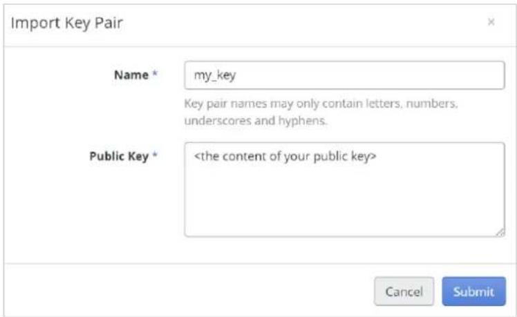
- The newly created key pair will be displayed in the main window.
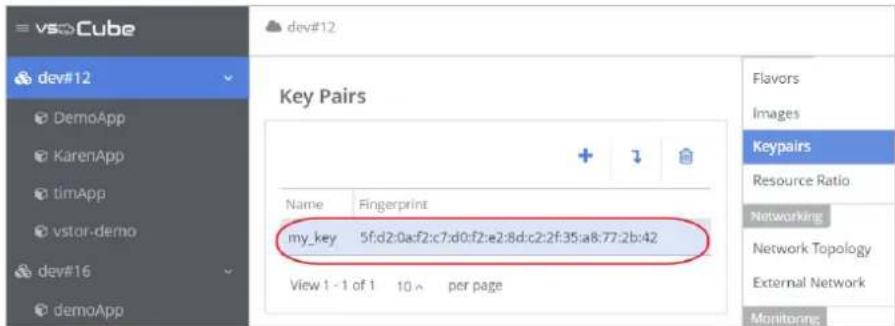
Delete Key Pair
To delete the key pair, select it and click the trashcan icon 📄

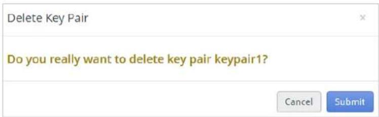
6.8. Security Groups
A Security Group is a set of rewall policies. Security Group Rules dene which trac is allowed into an instance. You can apply the most appropriate security group for each parcular instance.
6.8.1. Manage Security Group
All applicaons have a default Security Group which denies all incoming trac. The default security group cannot be deleted. You can add or delete security group rules to the default security group to change the rewall policies, or create your own security group.

See the above picture to locate Security Groups. There are 2 tables in the main window, on top is the Security Groups table and below is the table of rules for the selected security group.
Acons of security groups and rules are introduced below.
• + Create Security Group: Click to create a security group.
• Edit Security Group: Click the pencil buon to edit the selected security group.
- Delete Security Group: Click the trashcan buon to delete the selected security group.
• + Create Rule: Create a rule for the selected security group.
- Delete Rule: Delete selected rule.
6.8.2. Set Up Security Group Rules for accessing Instances
Security Group Rules dene which trac is allowed to get to the instance. A Security Group Rule consists of three main parts.
- Rule: You can select from the rule templates such as SSH, HTTP, or MYSQL, or use custom rules such as TCP, UDP, and ICMP.
- Open Port/Port Range: Choose either a single port or a range of ports.
- Remote: Specify the source of the trac to be allowed via this rule. Select either CIDR or Security Group. Selecng Security Group as the source will allow any instance in that Security Group to access any other instance.

flowchart
graph TD
    A["Add Rule"] --> B["Rule: Select rule template or use custom rules, such as TCP, UDP and ICMP."]
    B --> C["Security Group"]
    C --> D["default"]
    D --> E["Rule *"]
    E --> F["Custom TCP Rule"]
    F --> G["Direction *"]
    G --> H["Ingress Egress"]
    G --> I["Open Port *"]
    I --> J["Port Port Range"]
    J --> K["Port ? *"]
    K --> L["Example: 80"]
    M["Remote"] --> N["CIDR Security Group"]
    O["Port/Port Range"] --> P["Choose either a single port or a range of ports."]
    Q["Remote"] --> R["CIDR Security Group"]
    S["0.0.0.0/0"] --> T["End"]
To allow incoming network trac into an instance we need to add at least 2 rules.
- Rule-for-SSH: To access an instance by SSH, you need to create a rule to allow SSH packages into the instance.
- Rule-for-PING: If you want to use the "ping" command to validate the instance IP address, you need to create a rule to allow ICMP packages to access the instance.
| Rule-for-SSH | |
| Allow SSH port 22 to open for requests from any IP address. | |
| Rule | SSH |
| Direcon | N/A |
| Remote | CIDR |
| CIDR | 0.0.0.0/0 |
| Rule-for-PING | |
| Allow instances to receive all incoming ICMP packets. | |
| Rule | All ICMP |
| Direcon | Ingress |
| Remote | CIDR |
| CIDR | 0.0.0.0/0 |
Follow these steps to add rules to the default security group.
- Select the applicaon on the le sidebar.
- Select Security Groups under Compute on the right menu.
- Click the row to select a security group in the main window.
- Click the + icon in the Rules of default secon to open the Create Rule panel.

- Enter the value of Rule-for-SSH in the form, and click Submit.

- Enter the value of Rule-for-PING in the form, and click Submit.
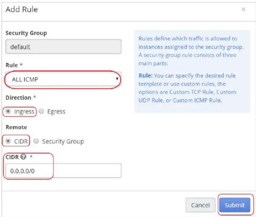
The two added rules will be displayed in the main window, Rules of default secon.
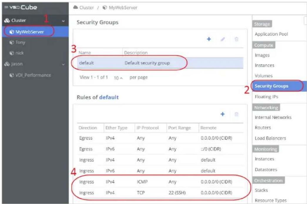
6.9. Resource Rao
The Resource Rao opon shows the resource rao seng of each node in the cluster, which means the resources, CPU and RAM, can be used to overprovision.
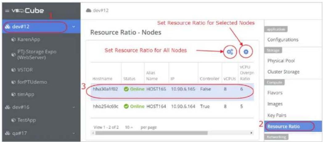
To set the resource rao of a specic node, click the single gear icon . Ifeseng all of the nodes, then click the tree gear icon .You will be asked to specify the resource provision sengs.
Overprovision with 1 rao, meaning the resource cannot be over-provisioned. Overprovision with 2 rao, meaning the resource can be over-provisioned 2 mes the available physical resources. When you nished, click Submit. The new sengs will be applied immediately.
In general, there are three scenarios.
No Overprovisioning
- Set up resource rao with 1 for both vCPU and memory.
- Once physical vCPU/vMemory is used up, no VM can be launched.
- Running VM's maintain constant performance level.
- Generally good for compute-intensive workloads and when performance degradaon is not desirable.
Medium Level of Overprovision
• Overprovision with 5 to 1 rao for vCPU and 1.5 to 1 rao for memory.
- It is good to obtain a balance of allowing more workload and it can tolerate certain performance degradaons.
High Level of Overprovision
- Overprovision with 16 rao, meaning vCPU can be over-provisioned 16 mes the available physical resources.
- Has a bias toward allowing a lot of the workload to be provisioned and a high tolerance for performance degradaon under occasional overloaded conditions.
6.10. Floang IPs
6.10.1. Associate Floang IP to Instance
To access an instance from an external network, you need to associate a oang IP to the instance. Follow these steps:

- Select the applicaon on the le sidebar.
- Click Instances under Compute on the right menu.
- Select the target instance, in this example, myUbuntu, and make sure the Status of the instance is Acve.
- Click the down-arrow icon ▼ to open the drop-down menu and select Associate Floang IP to Instance.
- The Associate Floang IP to Instance window appears. Click the +icon.

- The Allocate Floang IP window appears. Select the external network just created as the Floang IP pool.
- Click Submit to allocate a oang IP.
- Go back to the Associate Floang IP to Instance window. In the Instance eld, select the instance just created. In this example, select "myUbuntu". Click Submit.
- Wait 5 to 10 seconds. The oang IP will be displayed in the IP eld of the instance. Save the IP address for later use.

6.10.2. Manage Floang IP

Floang IP is an applicaon resource. Floang IPs are independent in each applicaon. Therefore, don't forget to delete (release) surplus oang IPs in the applicaon, so that the oang IP resources could be used by other applicaons. To manage oang IPs, please follow these steps.
- Select an applicaon on the right sidebar.
- Select Floang IPs on the right menu. Then the table of oang IPs will be shown on the main window.
There are 4 buons on top of the table.
A. + Click the plus buon to allocate a oang IP from the IP pool of the external network.
B. Click the buon to associate the selected oang IP to an instance or disassociate the selected oang IP from an instance.
C. Click the buon to associate the selected oang IP to a port of load balancer or disassociate the selected oang IP from a port of load balancer. See 7.10 Load Balancer for more informaon.
D. 📋 Click the trashcan buon to delete (release) the selected oang IP.
There are 2 dierent devices that a oang IP could be associated to: instance and load balancer. To associate a oang IP to an instance, check the network of the instance rst. Make sure the subnet of the instance network is able to access the external network through the router. See 7.2 Build a Basic Network Environment for more informaon. To associate a oang IP to a port of load balancer, you need to conjure the load balancer rst. See 7.10 Load Balancer for more informaon.
7. Chapter 7. Networking
In this chapter you will learn how to build the network conguraons of the cluster.
Glossary
External Network
- A set of network conguraons of a cluster. Here, external means outside of VSkyCube.
- An external network may be the same as the public network, or it may be a private OA (Oce Automaon) network. It depends on the network environment.
- You can only create one external network conguration in one cluster.
Internal Network
- A set of private network conguraons of a cluster that is not public.
• Each applicaon has its own internal network sengs. - Internal networks are isolated from each other by default.
Subnet
- A network (both external and internal) contains one or more subnets. If you need mulple subnets, you should create one internal network conguraon and then add mulple subnets under the internal network.
Router
- A virtual router connects the internal and external networks.
7.1. Network Topology
Network Topology is the network structure of a cluster. You can easily see how your network is constructed and spot problem areas. You can drag objects to rearrange them and then click the Save buon to preserve the organizaon.
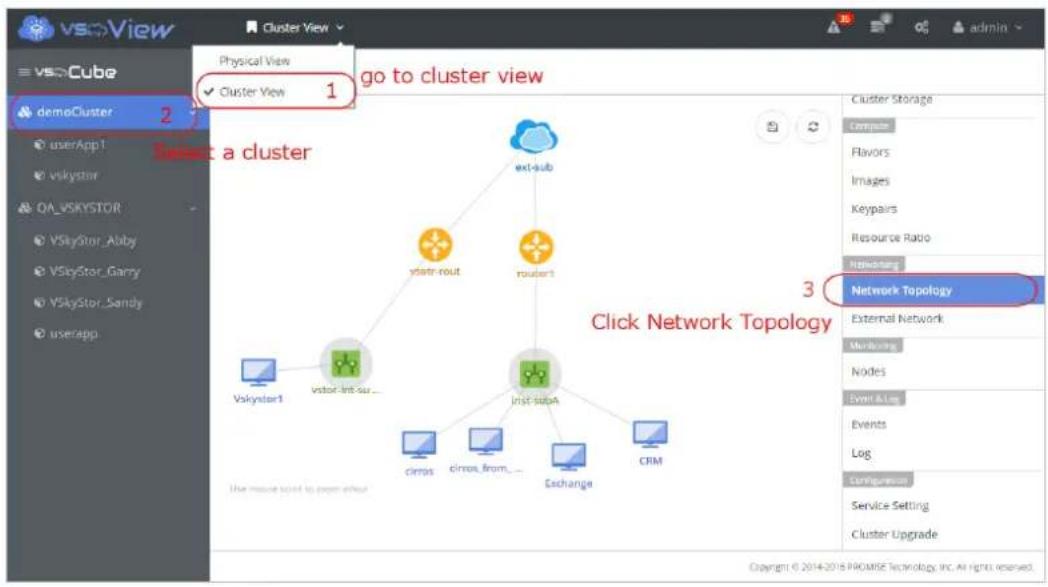

flowchart
graph TD
    A["Subnet of external network"] --> B["ext_sub"]
    C["Router"] --> D["router"]
    E["Subnet of internal network"] --> F["int_sub"]
    B --> G["Hold and drag elements to move. Click the Save button to store the current position."]
    F --> G
    G --> H["Service Setting"]
7.2. Build a Basic Network Environment
In this secon you will learn how to build a basic network environment for an instance. For the quick starter please refer to 7.3 Network Wizard.
Preparaon
- Create the applicaon before seng up the network environment. See 5.1 Create an Applicaon.
- Check the physical network sengs of the cluster. If the Service Network is congured, use the Service Network for the external network sengs. Otherwise, use the Management Network.
• You need to know the IP of the physical switch (gateway IP) for the external network. - You need to know the network address ^2 (CIDR) of the subnet for the external network.
- (Oponal) You need to know the available IP range ^3 for the cluster to use.
- (Oponal) You need to know the DNS IP/FQDN ^4 of the cluster.
Step Outline
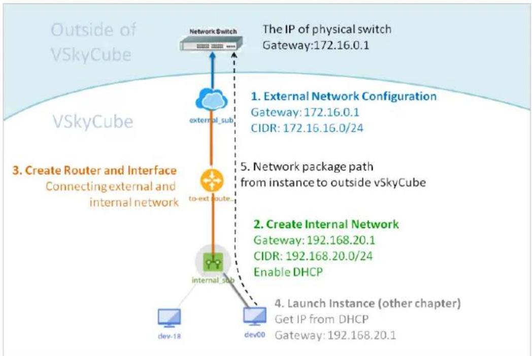
flowchart
graph TD
    A["Network switch"] --> B["external_sub"]
    B --> C["to-ext subnet"]
    C --> D["internal_sub"]
    D --> E["dev-18"]
    D --> F["dev00"]
    G["The IP of physical switch Gateway: 172.16.0.1"] --> H["1. External Network Configuration Gateway: 172.16.0.1 CIDR: 172.16.16.0/24"]
    G --> I["2. Create Internal Network Gateway: 192.168.20.1 CIDR: 192.168.20.0/24 Enable DHCP"]
    G --> J["3. Create Router and Interface Connecting external and internal network"]
    J --> K["Dev-18"]
    J --> L["Dev00"]
    M["4. Launch Instance (other chapter) Get IP from DHCP Gateway: 192.168.20.1"] --> N["Dev-18"]
Part 1. External Network Conguraon
- To create an external network for the cluster, select the cluster on the le sidebar, in this example, demoCluster, and then select External Network under Networking on the menu at the right. Click the +con to create an external network.

- Enter the following informaon in the Create External Network window.
• Name: What to call this external network.
- Provider Network Type: The physical mechanism for the virtual network to be implemented. Please do not change the default sengs.
- Admin State: The state of this external network. Please do not change the default settings.

- Switch to the Subnet tab on the top menu to congregate the subnet. Enter the following informaon.
• Name: A name for the subnet.
• Network address: Network address assigned to this subnet in CIDR format.
• IP version: The Internet Protocol version.
• Gateway IP: IP address of the gateway in the physical network.
- Disable Gateway: If there is no gateway in the physical network, check this box to disable the gateway.

-
(Oponal) Switch to the Subnet Detail tab for advanced subnet sengs. Enter the following informaon.
-
Allocaon Pools: VSkyCube automacally allocates the IP to the virtual device in the virtual network. If you want to limit your IP to a specific range, assign it in Allocaon Pools.
- DNS Name Servers: IP address of the DNS or FQDN (Fully Qualified Domain Name) server in the physical network.
• Stac Routes: Stac routes allow you to manually conjure the round entry.

Aer clicking Submit, the new external network will be displayed in the main window.

Part 2. Create an Internal Network
- To create an internal network for the applicaon, select the applicaon on the le sidebar, click Internal Networks under Networking on the right menu, and click the + icon.

- The Create Internal Network window appears. Enter the following informaon.
• Name: A name for the internal network.
• Admin state: The state of the network.
- Shared: Enable the Shared opon if you want to share this network with other applicaons.
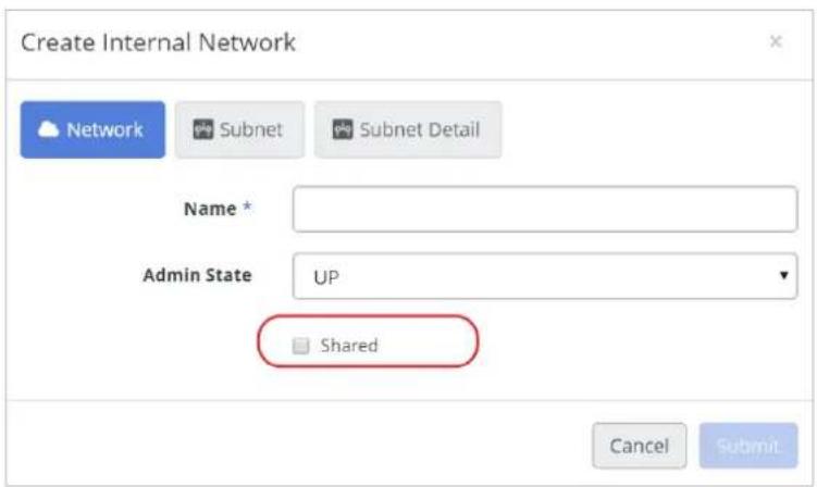
- Switch to the Subnet tab. Enter the following informaon.
• Name: A name for the subnet of the internal network.
- Network Address: This is the network address assigned to this subnet in CIDR format. Unlike the external network subnet, you have to assign the network address of the internal network yourself.
• IP Version: Specify the Internet Protocol version.
• Gateway IP: Specify the default gateway IP address of the subnet.
- Disable Gateway: Select the checkbox to disable the default gateway.

- (Oponal) Switch to the Subnet Detail tab on the top menu for advanced subnet sengs. Enter the following informaon.
- Allocaon Pools: VSkyCube automacally allocates an IP to the virtual device in the virtual network. If you want to limit your IP within a specific range, assign it in Allocaon Pools.
- DNS Name Servers: IP address of the DNS server in the physical network. If the subnet needs to connect to the external network, specify the DNS server.
• Stac Routes: Stac Routes are for manually configuring the round entry. - Enable DHCP: Enable DHCP service of the subnet. If you want to congregate IP addresses for instances manually, disable it.

Part 3. Create a Router and Interface
Create a virtual router connecng the external and internal networks.
- To create a router, select the applicaon on the le sidebar, click Routers under Networking on the right menu, and click the +con in the Routers secon.

- The Create Router window appears. Enter the following informaon.
• Name: A name for the router.
- Admin State: State of the router. Please do not change the default seng.
• Gateway to External Network: Select the external network just created.
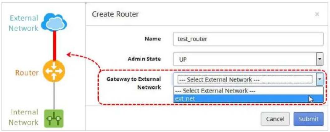
- Click Submit. The new router will appear in the Routers secon. Select it and click the +icon in the Interfaces secon.

-
The Create Interface window appears. Enter the following informaon, and then click Submit.
-
Subnet: Select the subnet of the internal network to connect it to the router.
- IP Address: Assign an IP address to the interface or leave it empty for auto assigning by VSkyCube.

The newly created interface appears in the Interfaces secon. Now the internal network is able to access the external network. You can go to Network Topology under Networking on the right to make sure the devices are connected.
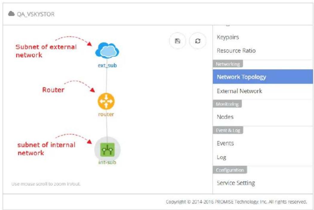
flowchart
graph TD
    A["Subnet of external network"] --> B["ext_sub"]
    C["Router"] --> D["router"]
    E["subnet of internal network"] --> F["int_sub"]
    B --> G["Service Setting"]
    D --> H["Keypairs"]
    D --> I["Resource Ratio"]
    D --> J["Networking"]
    D --> K["Network Topology"]
    D --> L["External Network"]
    D --> M["Monitoring"]
    D --> N["Nodes"]
    D --> O["Event & Log"]
    D --> P["Events"]
    D --> Q["Log"]
    D --> R["Configuration"]
FAQ
Q6. There are multiple NICs in my cluster, which sengs should I use to congregate the external network?
Check the network sengs of your cluster. Follow the steps described in the pictures below to open the Network Sengs panel.

- Case A. There are Management Network and Service Network sengs in the panel. In this case, use the Service Network sengs to congregate the external network.

- Case B. As shown in the picture below. If there are only Management Network sengs in the panel, then use the Management Network sengs to conjure the external network.

7.3. Network Wizard
Network Wizard lets you create a most basic network environment. Aer making an applicaon, open the wizard to complete your network conguraon.

As shown in picture below, the network wizard is basically a form to ll in.
- Internal Network CIDR: the CIDR for the internal network. Internal network is a private network for virtual machines/devices to communicate.
• DNS Name Servers: the DNS name servers for the internal network. - Connect to external network: Check to make the internal network able to access the external network. A router will be created if selected.
- External network CIDR: If the external network has not been congured, you are asked to ll-in the conguraon of the external network.
• Gateway IP: the gateway IP address of the external network. - Allocaon IP Pools: The IP ranges of the external network for the system to automacally assign to virtual machines and devices.

Aer creaon, the network topology will look like the picture below. During the process:
- An external network conguraon and the related subnet are set up.
- An internal network conguraon and the related subnet are set up.
- A router connecng the external subnet and the internal subnet is set up.
Now the basic network is built, and you are able to deploy the instances.

flowchart
graph TD
    A["ext_subnet"] --> B["route-201609 ..."]
    C["Router"] --> B
    D["subnet of external network"] --> A
    E["subnet of internal network"] --> C
Troubleshoong
Q7. Errors during the process of the network wizard.
The most common error is caused by the wrong conguraon. Follow these steps to clean up the conguraons and then try again.
-
Go to Router and delete the router and all the related interfaces just created. See 7.8 Manage Routers and Interfaces
-
Go to Internal Network and delete the network conguraon and the related subnet. See 7.5 Manage Internal Networks
-
(Oponal) Go to External Network and delete the network conguraon and the related subnet. See 7.4 Manage External Network. Note the external network is a shared resource of the applicaons, make sure that no other applicaon is using the external network before deleng it.
-
Now try run the Network Wizard again.
7.4. Manage External Network
Manage the external conguraon of the cluster.

Follow the steps described in the above picture to locate the External Network table. There are 4 buons on top of the table to manage the external network.
A. + Click this icon to create an external network conguraon. See 7.2 Build a Basic Network Environment for more informaon.
Noce
A cluster can only create an external network and one subnet conguraon.
B. View details of the selected network.
C. Edit the conguraon of the selected network.
D. Delete the selected network conguraon.
Noce
You need to delete all routers and subnets connected with the selected network before deleon. Otherwise the deleon might not work.
7.5. Manage Internal Networks
Manage the internal network conguraon of the applicaon.

Follow the descripon in above picture to locate the Internal Network table.
- Select the applicaon in the side bar.
- Click Internal Network from the menu.
- Click a row to select an internal network.
There are 4 buons on top of the table to manage internal network.
A. + Create an internal network conguraon. See 7.2 Build a Basic Network Environment for more informaon.
B. View details of the selected network.
C. Edit the conguraon of the selected network.
D. Click the trashcan icon to delete the network.
Noce
You will rst need to delete all routers and subnets connected with the selected network. Otherwise the deleon might not work.
7.5.1. Share Internal Network with Other Applicaons
An external network is open to all applicaons; however, internal networks are independent. To share an internal network with other applicaons, enable the network Share opon.
Create Internal Network
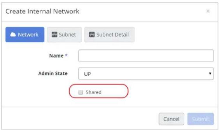
Edit Internal Network:

Noce
To disable the Share opon, you need to remove all the related devices connected with the shared network.
Shared internal networks can be accessed by all applicaons. The Applicaon column shows the owner of the network.

7.6. Manage Subnets
Manage the subnets in the external and internal network.
Locate Subnets the in External Network
The Subnets for each external network will be listed whenever you select the network.

Locate Subnets in the Internal Network
The Subnets for each internal network will be listed whenever you select the network.

There are 4 buons on top of the table to manage subnet:
A. + Create a subnet in the selected network. See 7.2 Build a Basic Network Environment for more informaon.
B. View details of the selected subnet.
C. Edit the conguraon of the selected subnet.
D. 📄 click the trashcan icon to delete the subnet.
7.7. Ports
Select a network and ports for the selected network will be listed in a table. Click a row to select the port, and then click the icon to view details.

7.8. Manage Routers and Interfaces
The Routers are used to connect the instances to the external network.
7.8.1. Routers

Select the applicaon and click Router on the right menu to locate the Routers table. There are 5 buons used for managing routers.
A. + create a router.
B. View details of the selected router
C. Edit the conguraon of selected router.
D. Use the ping command to verify the network conncon between the router and the target IP address.

E. Delete the selected router.
7.8.2. Use Ping on the Router to Verify the Network Connecon
You can use ping on the router to verify the network conneccon between the router and the target IP address.

Noce
To make ping available, there should be at least one internal interface connected with the router. If there's no internal interface connected to the router, the ping funcon may not work properly.
7.8.3. Interfaces

As shown in the picture above, there are 3 dierent types of interfaces:
External Gateway
Interface to external network.
Internal Interface
Interface to internal network.
SNAT
SNAT stands for Source Network Address Translaon. SNAT is commonly used to enable hosts with private addresses to communicate with servers over the Internet. When the router connects to an external network, one SNAT interface is automacally created for each connected internal network. It will be automacally deleted aer disconnectng.
Aer seng up the router, the interfaces corresponding to the router are listed in the table below the routers. There are 3 management acons for interfaces: Add Interface, View Details, and Delete Interface.

Create and Remove External Gateway
In the Create Router panel, select the external network in Gateway to External Network. You can add or remove it from Edit Router panel after the creation of router.
Note
For External Gateway, an IP address of an external network is needed. If you are running out of IP addresses in the external network, the acon may not work.

Create Internal Interface and SNAT
Open the Create Interface panel, the subnets will be listed in the Subnet drop-down list.
Noce
To add an internal network interface in another applicaon, you need to Share the network. See 7.5.1 Share Internal Network with Other Applicaons.
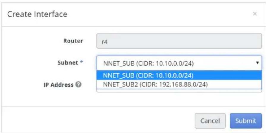
Click Submit; the new interfaces will be listed in the table. As shown below, interface (A) and (B) in the right picture are mapping to the corresponding interfaces on the le picture. If the router is connected to an external network, the SNAT will be created at the same me. Wait for few seconds unl the status of interfaces become Acve then proceed with the next acon.

flowchart
graph TD
    A["extSub"] -->|A| B["IR"]
    A -->|A| C["IR"]
    B -->|B| D["NNET_SUB"]
    C -->|C| E["NNET_SUB2"]
    D --> F["instance1"]
    E --> F
    B -->|r4| G["Cloud"]
    C -->|r5| H["Cloud"]

If the router is not connected to an external network, only an internal interface will exist. As shown in the pictures below, interfaces (C) and (D) in the right picture are mapping to the corresponding interfaces on the le picture.

flowchart
graph TD
    A["extSub"] -->|A| B["IR"]
    A -->|B| C["NNET_SUB"]
    A -->|C| D["NNET_SUB2"]
    B --> E["instance1"]
    D --> F["instance1"]
    B -->|r4| G["Cloud"]
    D -->|r5| H["Cloud"]

7.9. Stac Routes
In 7.2 Build a Basic Network Environment, we learned how to build a basic network environment for an instance. In this second you will learn how to build a network environment with stac routes.
- First you create a subnet, you are asked to assign an IP for the Gateway. See 7.2 Build a Basic Network Environment.
- Second, connect the subnet and the routers with interfaces.
- Third, check the IP addresses of the interfaces in the router. All network trac of the subnet will be sent to the router by the gateway interface. To make network trac get sent to another router, you need to set stac routes to make the rules apply. Stac routes allow you to manually congregate the round entries and they are xed and do not change if the network is changed or reconfigured.
For example, as shown in the picture below, there are 2 interfaces of subnet Int-subA11 connected to 2 dierent routers R1 and R2.

flowchart
graph TD
    A["ext-snet"] -->|192.168.11.1| B["Int-subA11"]
    C["R1"] -->|192.168.11.05| D["R2"]
    B -->|Gateway: 192.168.11.1| E["cirrosA"]
    D -->|Gateway: 192.168.22.1| F["cirrosB"]
    B --> G["192.168.22.1"]
    F --> H["192.168.22.102"]
The gateway of Inu-subA11 is 192.168.11.1, and the IP of the red interface is also 192.168.11.1. Therefore, R1 is the default router. All the network traffic of Int-subA11 will be sent to R1 by default. Therefore, the network traffic from instance cirrosA to cirrsB will fail because R1 will not connect to subnet Int-subB22. As shown in the picture below.
inet6 addr: fe80::f816:3eff:fe89:ca77/64 Scope:Link
UP BROADCAST RUNNING MULTICAST MTU:1400 Metric:1
RX packets:64 errors:0 dropped:0 overruns:0 frame:0
TX packets:99 errors:0 dropped:0 overruns:0 carrier:0
collisions:0 txqueuelen:1000
RX bytes:7167 (6.9 KiB) TX bytes:9936 (9.7 KiB)

lo Link encap:Local Loopback
inet addr:127.0.0.1 Mask:255.0.0.0
inet6 addr: ::1/128 Scope:Host
UP LOOPBACK RUNNING MTU:16436 Metric:1
RX packets:0 errors:0 dropped:0 overruns:0 frame:0
TX packets:0 errors:0 dropped:0 overruns:0 carrier:0
collisions:0 txqueuelen:0
RX bytes:0 (0.0 B) TX bytes:0 (0.0 B)

$ traceroute 192.168.22.102
traceroute to 192.168.22.102 (192.168.22.102), 30 hops max, 46 byte packets
1 192.168.11.1 (192.168.11.1) 0.246 ms 0.094 ms 0.056 ms
2 192.168.11.102 (192.168.11.102) 0.064 ms 0.107 ms 0.121 ms
3 10.90.6.254 (10.90.6.254) 0.488 ms 0.573 ms 0.511 ms
4 211-20-73-65.HINET-IP.hinet.net (211.20.73.65) 2.068 ms 2.352 ms 1.784 ms
5 * * *
6
The way to access instance cirrosB from cirrosA is to have network traffic sent to router R2, because R2 is able to access both subnets. In this case, you need to set the stac route of Int-subA11. To make the network trac from source Int-subA11 to desnaon Int-subB22 get sent via the interface 192.168.11.106 (marked in green), you need to add a stac route.
For example: 192.168.22.0/24: 192.168.11.106
Follow these steps.
- Go to Internal Network, and select the subnet. The subnet should be the source of the network package. For example, select the subnet Int-subA11 in the above scenario, and then click the Update buon to open the panel.

- Switch to the Subnet Detail tab. Add a set of stac routes in Stac Routes. For example: 192.168.22.0/24: 192.168.11.106. And then submit.
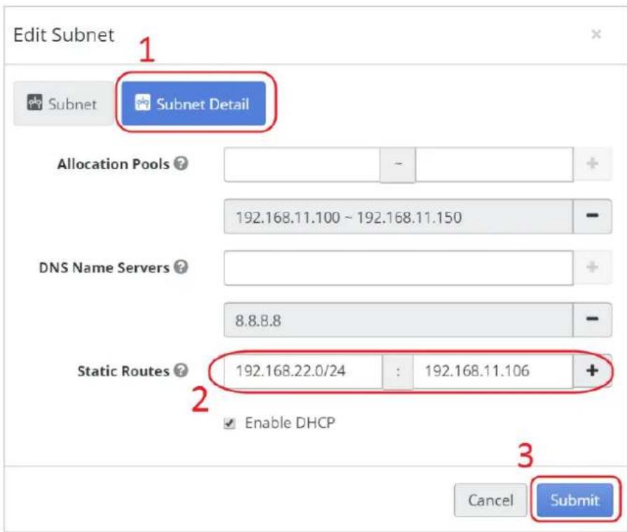
- The stac route seng will take eect immediately. However, the network service of the running instances should be restarted to get the new sengs. Go back to your instance, and reboot/restart the network.
- Try accessing the target IP address again. The rule of stac routes has been applied.
[ 0.361864] Registering the dns_resolver key type
[ 0.362397] registered taskstats version 1
[ 0.364259] Magic number: 0:300:533
[ 0.364656] bdi 1:11: hash matches
[ 0.365093] tty ttyS13: hash matches
[ 0.365642] rtc_cmos 00:01: setting system clock to 2016-05-06 13:30:21 UTC (
1462541421)
[ 0.366714] BIOS EDD facility v0.16 2004-Jun-25, 0 devices found
[ 0.367253] EDD information not available.
[ 0.501415] Freeing unused kernel memory: 924k freed
[ 0.501999] Write protecting the kernel read-only data: 12288k
[ 0.505796] Freeing unused kernel memory: 1600k freed
[ 0.508363] Freeing unused kernel memory: 1188k freed

further output written to /dev/ttyS0

login as 'cirros' user. default password: 'cubswin):'. use 'sudo' for root.
cirrosa login: cirros

Password:
$ traceroute 192.168.22.102
traceroute to 192.168.22.102 (192.168.22.102), 30 hops max, 46 byte packets
1 192.168.11.106 (192.168.11.106) 0.598 ms 0.164 ms 0.070 ms
2 192.168.22.102 (192.168.22.102) 0.585 ms 0.227 ms 0.132 ms
7.10. Load Balancer
A load balancer is an advanced networking service that provides load balancing for virtual machines. It spreads incoming requests across mulple instances to reduce the load. It is widely used on large websites and network services.
A load balancer includes the following components – Load Balancer Pool, VIPs, Members, and Health Monitors. The following table describes their funcons.
| Component | Descripon |
| Load Balancer Pool | A pool holds a list of members that serve content through the load balancer. |
| VIPs | Virtual IP sengs of the load balancer.A VIP owns an IP address assigned from a subnet of an internal network. You need to associate a oang IP on the VIP to make it accessible from an external network. |
| Members | Members are instances that handle trac behind a load balancer. Each member is specied by the IP address and port that it uses to serve trac.The incoming network requests will be balanced between the various members. |
| Health Monitors | Members may go oine from me to me and health monitors divert trac away from members that are not responding properly. VSkyCube provides availability monitoring with the ping, TCP, HTTP, and HTTPS GET methods. Health monitors are implemented to determine whether pool members are available to handle requests. Health monitors must be associated with pools to take eect. |
7.10.1. Build a Basic Load Balancer for a Website
Step Outline:
- Step 1. Create a Load Balancer Pool
- Step 2. Create a VIP for the Pool
- Step 3. Launch Instances
- Step 4. Congure Security Group
- Step 5. Add the Members to the Pool
- Step 6. Setup a Sample Web Server
- Step 7. Associate a Floang IP Address to the VIP Port
- Step 8. Create a Health Monitor and Associate it with the Pool
- Step 9. Validate the Results
Below is the step-by-step descripon of how to build a basic load balancer for a website.
Step 1. Create a Load Balancer Pool
- From the Load Balancers' Pool tab, click the + icon to open the Create Pool dialog box.
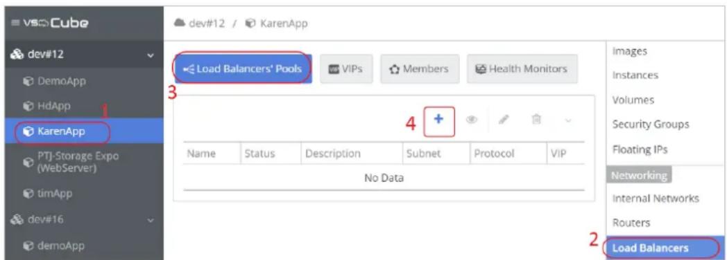
-
Fill in the following informaon and click Submit.
-
Subnet: The subnet that the instances are attached to and will be used to load balance against.
- Protocol: Choose the appropriate protocol (such as http for web requests).
- Load Balancing Method: Choose the appropriate method. See 7.10.2 Load Balancer Pool for more informaon.
- Admin State: Select UP to allow network trac.

The new load balancer will be listed in the table.

Step 2. Create a VIP for the Pool
- Open the Create VIP dialog box by clicking the + icon.
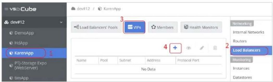
-
Fill-in the informaon and click Submit.
-
Pool: A pool can have one VIP. Select the pool to which the VIP should belong.
-
Subnet: Choose the target subnet of the VIP.
-
Specify a free IP address from the selected subnet: This is an available IP address out of the same subnet range that the instances are located. This IP address will be used as the virtual IP and will be listed in VIP.
- Protocol Port: This is the port that the VIP will be listening on. It must match that of the incoming requests.
- Protocol: Should be the same as the protocol of the selected pool.
- Session persistence: Session persistence ensures incoming requests are routed to the same instance within a pool of mulple instances. The load balance mechanism supports round decisions based on cookies and source IP address.
- Connecon Limit: Maximum numbers of connecons allowed for the VIP. Leave this eld empty or enter '-1' to cancel the limitaon.

- Aer subming the form, the newly create VIP will be listed in the table.

Step 3. Launch Instances
Launch the instances to be controlled by the load balancer. You can either use your own instances or launch two Fedora or Ubuntu images for pracce. In this scenario, we will launch two Ubuntu instances and execute the Python module installed that will act as a basic web server.
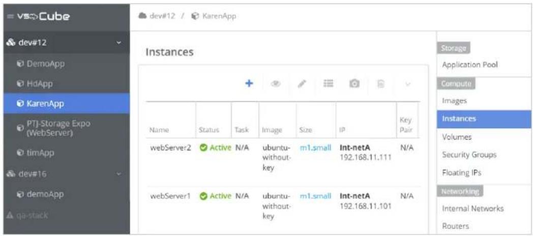
Step 4. Congure Security Group
To allow for ping, SSH, and HTTP access to the two instances that were launched in Step 3, open up the Security Group Rules and add the relevant rules. Switch to the Security Groups table and add the rule. You can either choose the default security group or create a new one. Make sure the security group is applied to the instances. See 6.8 Security Groups for more informaon.

In this example, we added 2 rules.
- Allow incoming network packages with protocol TCP and port 22. (SSH)
- Allow incoming network packages with protocol TCP and port 80. (HTTP)

Step 5. Add the Members to the Pool
Once the instances are launched they will show up in the Create Members panel. Follow these steps to open the panel.
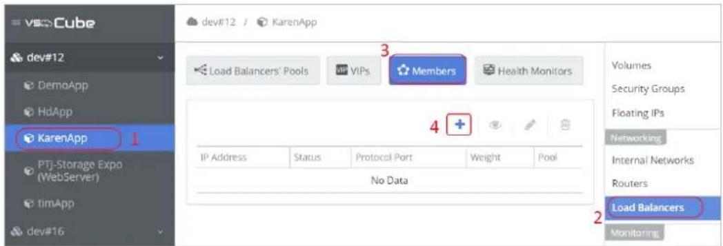
Fill-in the form in the Create Member panel and click Submit.
• Pool: Select the pool to which the member belongs.
• Member Source: Select members either from acve instances or from IP addresses.
- Weight: Relave part of requests this pool member serves compared to others. The same weight will be applied to all the selected members and can be modified later. Weight must be in the range 1 to 256.
- Protocol Port: This is the back-end port between the VIP and the member servers. The same port will be used for all the selected members and can be modified later. The port should match the sengs in Step 4, security groups, so that the network packages will be allowed access to the instances.
- Admin State: Select UP to allow incoming network packages.

Aer subming, the members of the pool will be listed in the table.
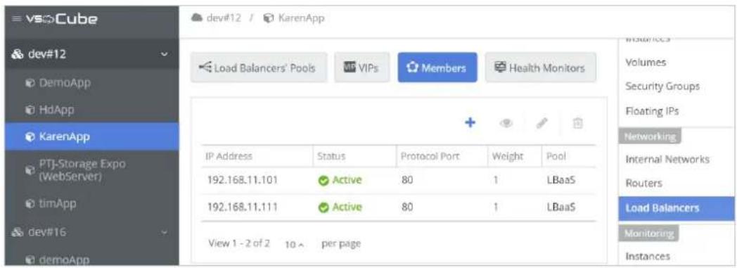
Step 6. Setup a Sample Web Server
Congure a basic index.html le on each node and run the Python module that will act as the basic web server.
Follow these steps.
- Associate a oang IP to one of the members.

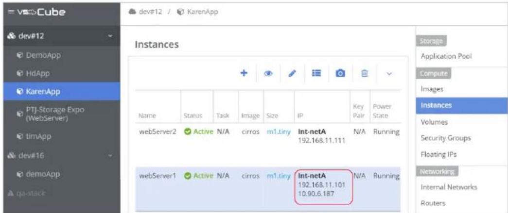
- Use SSH to log-in to the instance.

![administrator@host-192-168-11-101: ~ [80x24] 連線(C) 編輯(E) 檢視(V) 視窗(W) 選項(O) 說明(H) login as: administrator administrator@10.90.6.187's password: ***** Welcome to Ubuntu 14.04.2 LTS (GNU/Linux 3.16.0-30-generic x86_64) * Documentation: https://help.ubuntu.com/ System information as of Wed May 25 18:22:05 CST 2016 System load: 0.04 Processes: 80 Usage of /: 29.3% of 3.61GB Users logged in: 0 Memory usage: 3% IP address for eth0: 192.168.11.101 Swap usage: 0% Graph this data and manage this system at: https://landscape.canonical.com/ 106 packages can be updated. 61 updates are security updates. Last login: Wed May 25 18:22:05 2016 from 10.90.7.33](/content/2026/06/1199685/images/567e0593cde82a8681a6e00bb36eae677e19829f3976e07eace91ecceae8c4cd.jpg)
- Aer logging in, create an index.html in the local folder and execute this command:
$ vi index.html
administrator@host-192-168-11-101:~$ vi index.html
administrator@host-192-168-11-101:~$ ls
index.html
- Type some content for the website in the le, and save it. Then start an HTTP server with the python command and make it run in the background. For more informaon about SimpleHTTPServer, please refer to hps://docs.python.org/2/library/simplehpserver.html
$ sudo su
$ nohup python -m SimpleHTTPServer <port_number> &
- The port number should match the sengs from the previous step. For example.
$ nohup python -m SimpleHTTPServer 80 &
administrator@host-192-168-11-113:~$
administrator@host-192-168-11-113:~$ sudo su
sudo: unable to resolve host host-192-168-11-113
root@host-192-168-11-113:/home/administrator# nohup python -m SimpleHTTPServer 80 &
[1] 1065
root@host-192-168-11-113:/home/administrator#
- Test the web server with the browser. Open the browser and enter URL:
http://<instance_floating_IP>:<port>

- Close the SSH conncon and disassociate the oang IP.
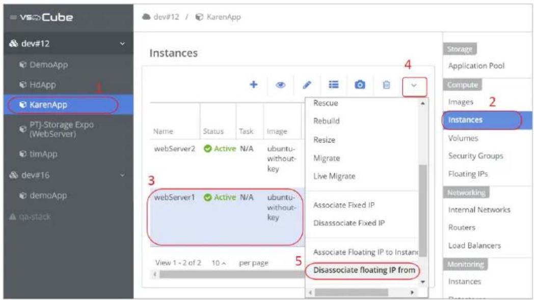
- Repeat 1\~7 with another instance to set up all the web servers.
Step 7. Associate a Floang IP Address to the VIP Port
Associate a oang IP to the VIP port, so that the VIP will be accessible from an external network.
Follow these steps to open the Associate Floang IP to Port panel.

Select the networks to which the VIP belongs and then select the VIP port in the Ports drop-down list. The networks should be the same as in Step 2, Create a VIP.

Aer subming, the oang IP will be associated to the VIP.

Step 8. Create a Health Monitor and Associate it with the Pool
To create a health monitor to track the health status of the members, open the Create Health Monitor panel.
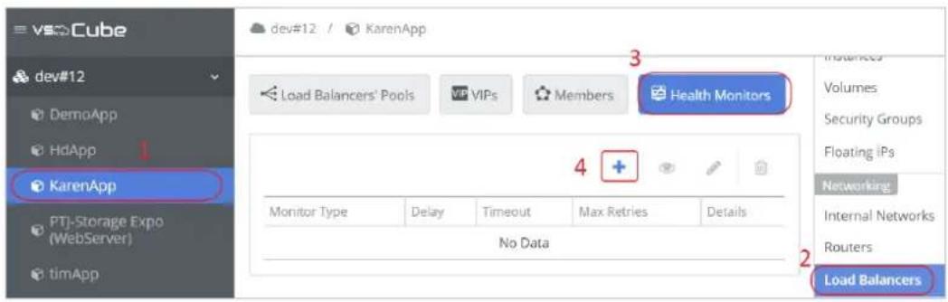
Fill-in the form in the panel, and submit.
- Type: The protocol to monitor the member.
- Delay: The minimum me in seconds between regular checks of a member.
- Timeout: The maximum me in seconds for a monitor to wait for a reply.
- Max Retries: Number of permissible failures before changing the status of a member to inacve.
- URL: The URL for health monitoring. Here we use the root path of the web server.
• Expected HTTP Status Codes: Expected status code of the reply from the web server.
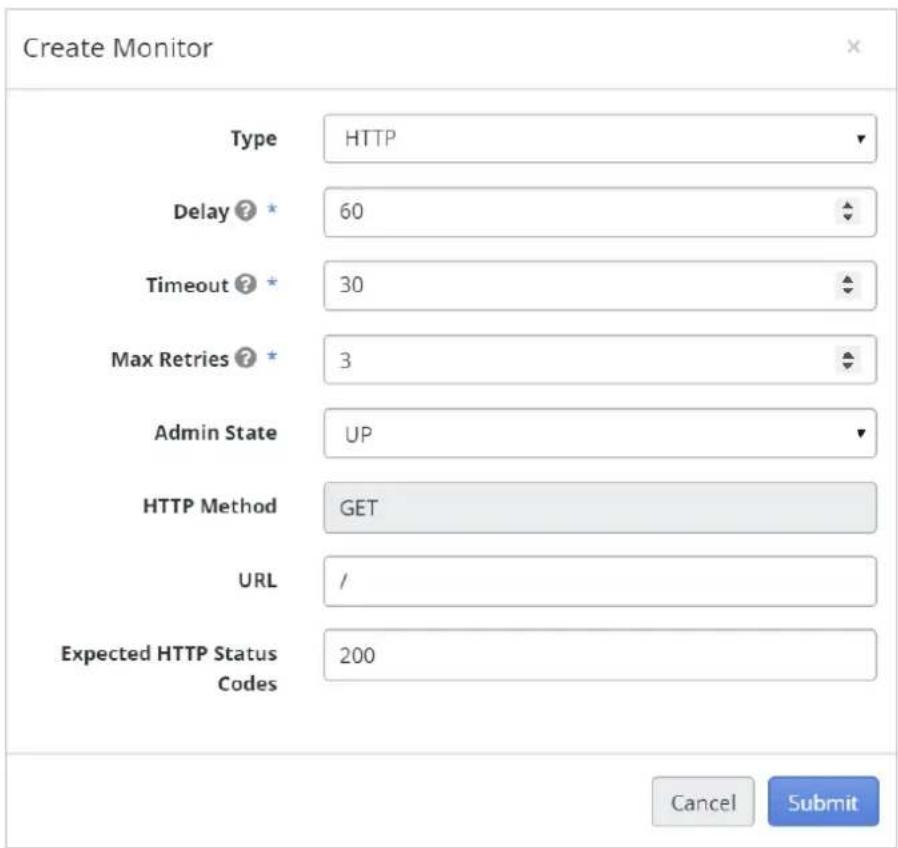
Aer subming, the health monitor will be listed in the table.

Associate the health monitor to the pool.


Step 9. Validate the Results
Access the oang IP, and refresh the pages to validate the results.
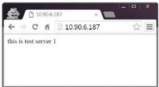
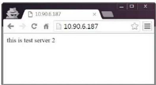
7.10.2. Load Balancer Pool
For load balancers, incoming requests are distributed using one of these load balancing methods. These methods can be dened when creang the Load Balancer Pool.
Round robin
Rotates requests evenly between mulple instances.
Source IP
Requests from a unique source IP address are consistently directed to the same instance.
Least connecons
Allocates requests to the instance with the least number of acve connecons
To manage the load balancer pool, please follow these steps.

-
Select the applicaon listed on the le sidebar.
-
Click Load Balancers on the right menu.
-
Click on a row to select a pool.
-
Click the arrow icon to open the drop-down menu.
As shown in above picture, there are acon buons to manage Load Balancer Pool.
• A. + Create a load balancer pool. See 7.10.1 Build a Basic Load Balancer for a Website.
B. View the detailed informaon for the selected load balancers pool.
• C. Edit the sengs of the selected pool.
• D. Delete the selected pool.
• E. Click to open the drop-down menu.
- F. Create VIP: Same as the create acon in the VIP component. See 7.10.1 Build a Basic Load Balancer for a Website.
• G. Associate Health Monitor: Associate an exisng health monitor to the selected pool.

• H. Disassociate Health Monitor: Disassociate a health monitor from the selected pool.

7.10.3. VIP
One load balancer pool can have one VIP.
Session Persistence
Load Balancer supports session persistence by ensuring incoming requests are routed to the same instance within a pool of mulple instances. Load Balancer supports round decisions based on cookies and the source IP address. Session persistence can be dened when creang a VIP.
To manage the VIPs, please follow these steps.

- Select the applicaon listed on the le sidebar.
- Click Load Balancers on the right menu.
- Switch to the VIPs tab.
- Click on a row to select an exisng VIP.
As shown in above picture, there are acon buons to manage VIPs:
- A. + Create a virtual IP for the load balancer. See 7.10.1 Build a Basic Load Balancer for a Website.
• B. View the detailed informaon for the selected VIP.
• C. Edit the sengs of the selected VIP.
• D. Delete the selected VIP.
7.10.4. Member
To manage members, please follow these steps.
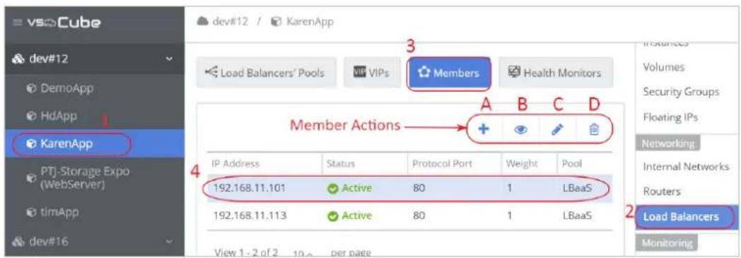
- Select the applicaon listed on the le sidebar.
- Click Load Balancers on the right menu.
- Switch to the Members tab.
- Click on a row to select a member.
As shown in above picture, there are acon buons to manage members:
• A. + Create members. See 7.10.1 Build a Basic Load Balancer for a Website.
• B. View the detailed informaon for the selected member.
C. Edit the properes of the selected member.
• D. Delete the selected member.
7.10.5. Health Monitor
A health monitor must be associated to a load balancer pool for the monitor to take eect. A health monitor can be applied to mulple pools.
To manage the health monitor, please follow these steps.

- Select the applicaon listed on the le sidebar.
- Click Load Balancers on the right menu.
- Switch to the Health Monitors tab.
- Click on a row to select a member.
As shown in above picture, there are acon buons to manage health monitors:
• A. + Create a health monitor. See 7.10.1 Build a Basic Load Balancer for a Website for more informaon.
• B. View the detailed informaon for the selected health monitor.
• C. Edit the properes of the selected health monitor.
• D. Delete the selected health monitor.
8. Chapter 8. Storage
Use the informaon in this secon for storage management including physical and virtual storage.
8.1. Physical Pool
Select the cluster from the le sidebar, and select Physical Pool on the right menu. The physical storage use is shown at the top of the page, and below is a list of physical disks.
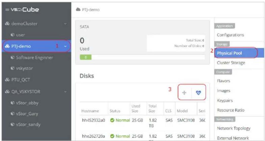
Add Physical Disks

Follow these steps to add a physical disk.
- Insert the new physical disks into the node.
-
Go to Physical Pool, and click the Scan Disk buon to search for new disks.
-
The table of disks will be refreshed, and a row of newly inserted disks will be listed in the table.
The status of the newly inserted disk will be Standby. Click the row to select a new disk.
- Click the +con to add the selected disk into the cluster.
8.2. Cluster Storage
The Cluster Storage opon shows the usage of the virtual storage reserved for systems in the cluster.
8.2.1. Image Storage

This is the system storage stores all the images in the cluster. One of the system disk will be used by default. Therefore, the value of Applicaon and Datastore will be (Default Cluster Storage)

You can extend the capacity or improve the data protecon by migrate data to a larger/high protecon datastore. Click buon Migrate Data, and select a target datastore from the dropdown list. Aer submit, the data will be migrate to the new datastore. The migraton procedure takes a while according to the size of the data.
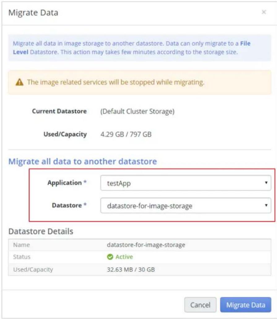
Note
The image related services will be stopped while migrang.
When the migraon nishes, the datastore informaon will be listed in the table.

8.2.1.1. Create a Datastore for Image Storage
The requirement for image storage is a File Level datastore. As shown in the picture below, remember to choose File Level for Datastore Type when creang datastore. See 8.4.1 Datastore Properes and Hardware Requirements for more informaon.
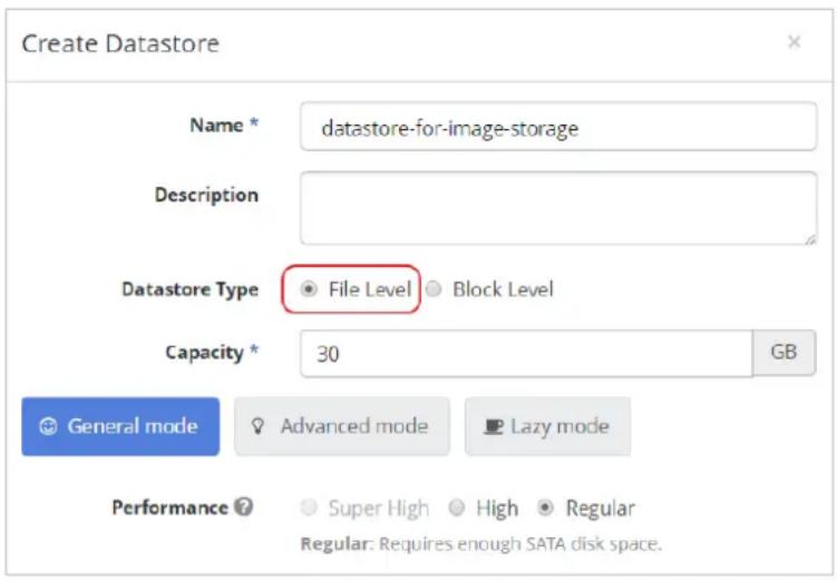
8.2.1.2. Create a RAIN Datastore for Image Storage (Cluster HA)
To support cluster HA, a fault tolerance datastore of Image Storage is required to ensure the image service works properly if the node fails. Therefore, the requirements for the storage are (1) a File Level and (2) RAIN mechanism supported datastore.
As shown in the picture below, remember to choose File Level for Datastore Type and the RAIN enabled for Redundancy when creang the datastore. See 8.4.1 Datastore Properes and Hardware Requirements for more informaon.
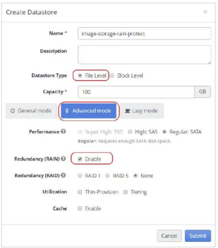
Note
If the datastore does not full the requirements, a warning message will appear when changing a worker to a controller. See 4.5.8 Change Node to Controller/Change Node to Worker for more informaon. Migrate the data to a fault tolerance datastore to pass the validaon.
8.2.2. Compute Storage
This is the system storage for all the instance images in the cluster.

8.3. Applicaon Pool
Applicaon Pool (App Pool)
Applicaon Pool is the storage capacity of an applicaon. You can only create one per applicaon.
Create an Applicaon Pool
- As shown in the image below, select an applicaon

- Select Applicaon Pool on the right menu
-
Click the plus buon to open the Create Applicaon Pool panel.
-
Assign the capacity, and then click submit. Then the creation of application pool is done.

8.4. Datastores
Datastores represent dierent types of virtual storage. You can specify the properes of the virtual storage.
Volume
Volume is the data volume for an instance (VM) to use. You must specify a type of datastore when you create a volume. The properes of the volume depend on the datastore it belongs to.
8.4.1. Datastore Properes and Hardware Requirements
Here are properes of a datastore; each of them has dierent hardware requirements.

Disk Type
- System
This opon is usually hidden. Only if the selected applicaon is a VSky series applicaon will this opon be visible. When this opon is selected, a datastore for system use is created.
- File Level
With this opon selected, a GlusterFS volume will be created. The volume can be accessed with a GlusterFS nave interface.
- Block Level
Create a block level datastore for instance use.
Performance
Performance indicates the physical drive type and speed. If there are not enough physical drives corresponding to the selected opon, the creaon will fail.
• Super High: generally SSD drives.
• High: generally SAS drives.
• Regular: generally SATA drives.
Redundancy (Fault Tolerance)
This property indicates the data protecon mechanism. High redundancy oers high protecon. However, it requires more disk space. To create a RAID datastore, make sure you have at least 3 available physical drives corresponding to the selected opon in the Performance eld.
- High
With RAIN ^5 and RAID 5 properes.
3 or more online nodes are needed in a cluster to create a high redundancy datastore.
- Regular
With RAIN or RAID 5 properes.
Noce
If there are 3 or more online nodes in a cluster, create a datastore with RAIN. If there are less than 3 online nodes in a cluster, create a datastore with RAID.
- None
Create a datastore without a data protecon mechanism.
Ulizaon
- Thin-Provision
Create a datastore with the thin-provision property. There are no further hardware requirements.
- Tiering
Create a datastore with ering property. The Performance selecon needs to be High or Super High. Regular will not support ering.
Cache
To create a datastore with the cache property, please make sure there is an SSD drive in the cluster.
8.4.2. Check Hardware Disk Resources
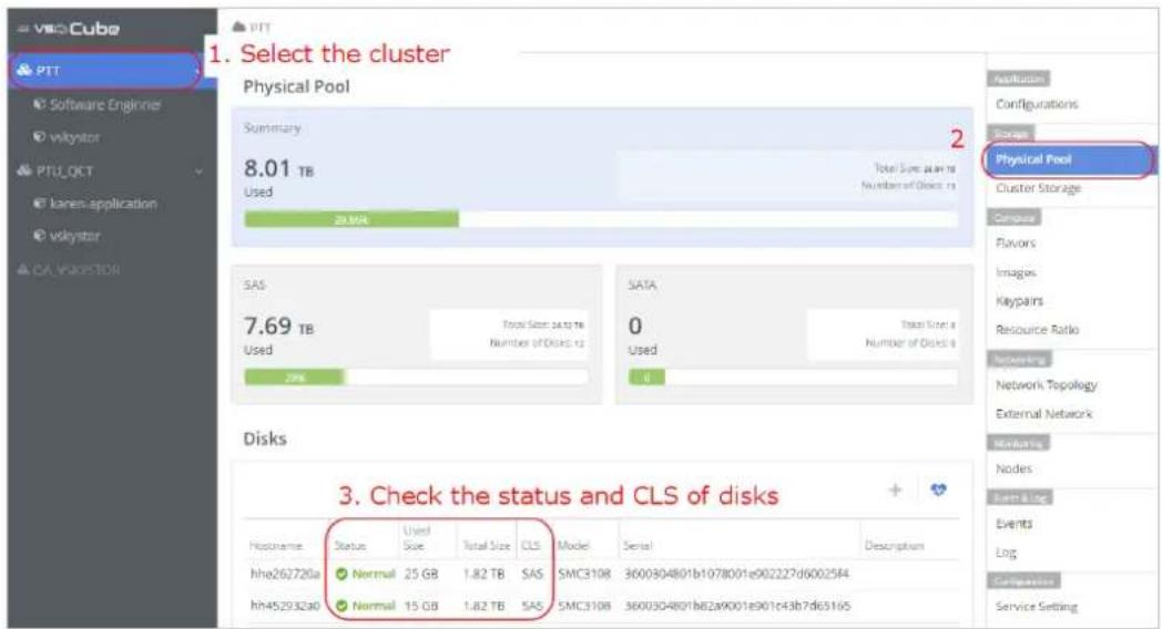
- Select the cluster listed in the sidebar.
- Select Physical Pool in the Cluster-Related menu.
- Check the Status and CLS of the disks.
The status should be Normal. If the disk is in another state, the disk is not available to create a datastore. The CLS type should match the selecon of Performance when you create a datastore. For example, if there are only SAS drives listed in the table, you should select High performance. If there are only SATA drives listed in the table, you should select Regular performance.
8.4.3. Create Datastore

- Select an applicaon and then click Applicaon Pool on the Applicaon-Related menu.
- Make sure there is an applicaon pool listed in the table. If not, see 8.3 Applicaon Pool to create one.
- Click the plus icon + to open the Create Datastore panel.
- Fill out the form in the panel. For Datastore Type, select Block Level in general. For other elds please refer to 8.4.1 Datastore Properes and Hardware Requirements.
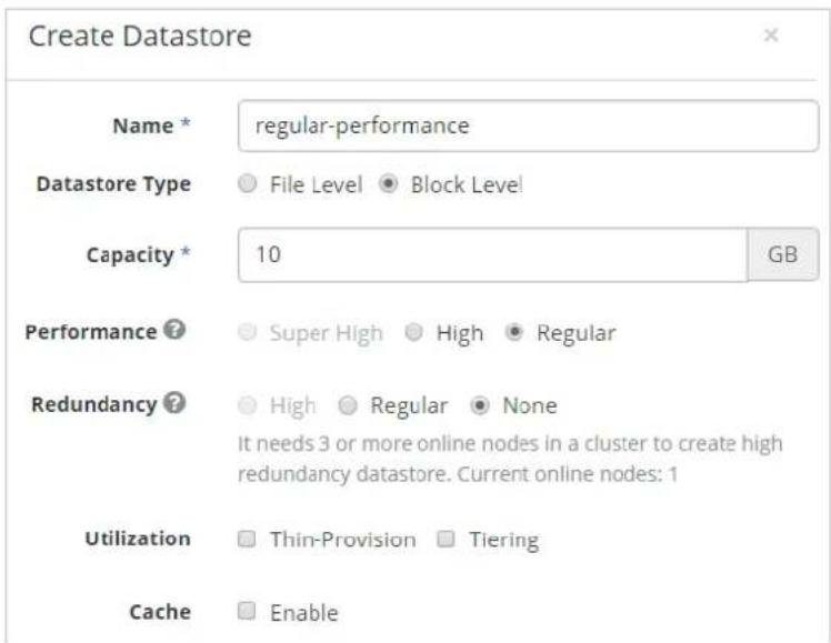
- Click Submit to start creang the datastore. It takes about 1 minute to create a 10 Gigabytes datastore. If cream fails, check the 8.4.4 Troubleshoong secon.
8.4.4. Troubleshoong
Q8. Creaon failed and a Re-Create dialog box popped up.


Recreate the datastore with lower performance.
This happens when you do not have enough resources to create a datastore which matches your requirements. Follow the steps below to recreate a datastore with lower performance.
- Click Yes to recreate with lower performance.
- Click No to close the dialog box, and check if your physical resources sasfy the hardware requirements. Then, create a datastore again with the correct sengs.
8.5. Volume
Volumes
A volume is a block device that can be aached to an instance. You must specify a type of datastore when you create a volume. The properes of the volume depend on the datastore it belongs to. A bootable volume can be launched as an instance.
Volume Snapshots
A volume snapshot is a point-in-me copy of a volume. Use Volume Snapshots to back up volumes.
8.5.1. Create Volume
A datastore is required when creang a volume. Create a datastore and make sure the status is Acve. See 8.4 Datastores.
- Follow the steps marked in the picture below to open the Create Volume panel.

-
Fill-in the form.
-
Datastore: The properes of the volume such as disk performance and data protecon mechanism are depend on the datastore it belongs to. The details of the selected datastore will be shown on the right table.
• Size: Specify the disk size. - Volume Source indicates the source data of the volume. If you want to create a general virtual disk to store data, select No source, empty volume.
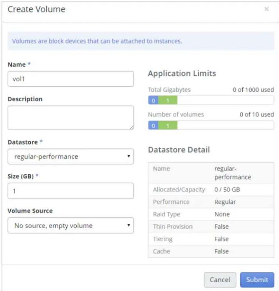
- Click Submit. The new volume will be listed in the table, and the status of the volume should be Available within few seconds. Now you can start to use the volume.
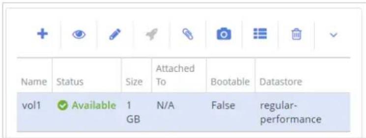
8.5.2. Aach a Volume to an Instance
Before aaching the volume, make sure you have an instance and the status of the instance is Acve. Follow these steps to each volume to an instance.
- Click a row to select a volume.

- Click the paperclip icon 📋 to open the Manage Aachments panel.
- Select the target instance from the drop-down menu, and click the Aach Volume buon.

- Wait 10 to 30 seconds. The status of the volume will be In-Use and the mount path will be listed under Aached To. For example: cirros on /dev/vdb. This means that the volume is aached to instance cirros and the mount path is /dev/vdb.

- Log in to the target instance via SSH and you will see a new device mounted on path /dev/vdb.

8.5.3. Volume Source
No source, empty volume.
This is the most common opon. The created volume will be enrely empty with no paron table and no le system with this opon selected. It can be aached to an instance and store your data. Remember to format it the rst me it is opened.
Snapshot
Create a volume from a volume snapshot. You're asked to select a volume snapshot when creang a volume. The snapshot will be a copy of the selected volume snapshot.

Image
Create a volume from an image. You're asked to select an image when creang a volume. It will be a copy of the image and able to be launched as an instance. The volume created from an image is also called a bootable volume. A bootable volume can only be launched one instance at a me.
Noce
The bootable volume will be the system volume of the instance aer it is launched. Therefore, the size of the volume will be the size of the instance. Choose the proper size for your instance.

Aer creaon, the Bootable column in the table of volumes will be labeled True.
| Name | Status | Size | Attached To | Bootable | Datastore |
| bootVolume | ✓ Available | 30GB | N/A | True | ds_test |
Aer launching an instance from a volume, the status of the volume will be In-Use.

Volume
Create a volume from an exisng volume. You're asked to select a volume when creang a volume. It will be a copy of the selected volume.

Noce
Some acons are blocked for a volume created from another volume such as: Extend Volume, Take Snapshot, Aach to Instance, and Upload to Image.
8.5.4. How to Check Volume Source aer Creaon
Use Volume Details to check volume source aer cream. See 8.5.5 Volume Acons.
In the Volume Details panel, Volume Source is displayed in the Specicaons table as shown in the following picture.

In some situaons, a volume may contain mulple sources, as shown in the following picture.
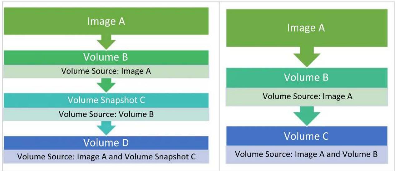
flowchart
graph TD
    A["Image A"] --> B["Volume B\nVolume Source: Image A"]
    B --> C["Volume Snapshot C\nVolume Source: Volume B"]
    C --> D["Volume D\nVolume Source: Image A and Volume Snapshot C"]

    E["Image A"] --> F["Volume B\nVolume Source: Image A"]
    F --> G["Volume C\nVolume Source: Image A and Volume B"]
8.5.5. Volume Acons

As shown in the above picture, the acon buons of volume are listed on top of the volume table and introduced in below from le to right:
| A | + | Create a volume. See 8.5.1 Create Volume. |
| B | View details of the selected volume. | |
| C | Edit the selected volume. | |
| D | To launch the selected volume as an instance. Only a bootable volume can be launched. See 8.5.3 Volume Source. | |
| E | To each and detach the selected volume to an instance. See 8.5.2 Aach a Volume to an Instance. | |
| F | Create a volume snapshot selected volume. See 8.5.6 Volume Snapshot. | |
| G | Edit the metadata of volumes. You can create your own metadata. Metadata created by system is not allowed to edit. | |
| H | Delete selected volume. | |
| I | Click to open the drop down menu. | |
| J | Extend Volume: Extend the size of the selected volume. | |
| K | Upload to Image: Upload the volume to the Image Service as an image. | |
| L | Set Volume to Read-Only/Cancel Read-Only for Volume: Set and cancel volume to read-only. | |
8.5.6. Volume Snapshot
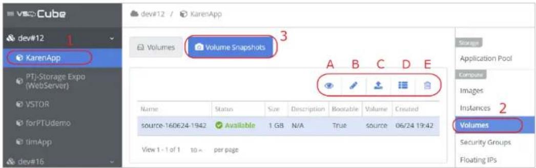
Go to Volumes service and click tab Volume Snapshots. All the snapshots are listed in the table. The Volume column shows the source volume for the snapshot. As shown in the above picture, the acon buons of volume snapshots are listed on top of the volume table and introduced below from le to right:
• A. View details of the selected snapshot.
• B. Edit the selected snapshot.
C. ↑ Create a volume with this snapshot as the volume source. See 8.5.3 Volume Source.
Noce
Volume snapshots are not allowed to be used directly. You need to create a volume from the volume snapshot, and then use the volume instead of the snapshot.
• D. Edit the metadata of the selected snapshot.
• E. Delete the selected snapshot.
8.5.7. Troubleshoong
Q9. What does the warning message that pops up, selected volume has referenced to another volume, means?
Selected volume has referenced to another volume means the selected volume is created with another volume as a volume source. Some acons such as extending and taking a snapshot are not allowed. See 8.5.3 Volume Source for more informaon. The warning message may look like the picture below.

Q10. What does the warning message that pops up, selected volume has independent snapshots, means?
Selected volume has independent snapshots means there exists volume snapshots related to the selected volume. Delete the related snapshots rst, and then you can perform the acons. The warning message may look like the picture below.

9. Chapter 9. Monitoring
Use the informaon in this secon for relevant monitoring.
9.1. Nodes Monitoring
The Nodes Monitoring opon allows you to monitor the status of the physical nodes. The hardware-related informaon can allow you to audit. For instance, Monitor Class can see the CPU, load, memory, and interface status. You also can apply Iters to decide node, me interval, and hardware variables to monitor.

9.2. Instance Monitoring
The Instances Monitoring opon allows you to keep track of the instance status. Instance-related informaon can allow you to audit. For example, the Monitor Class can see the CPU, disk, memory, and interface status. You can also apply Iters to decide the instance, me interval, and instance-related variable to monitor.
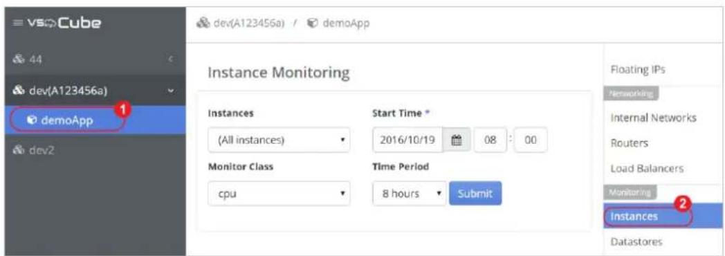
9.3. Datastores Monitoring
The Datastores Monitoring opon allows you to see the condion of the datastores. The datastore-related informaon is supplied so you can audit. You can apply Iters to decide on the datastore and me interval you want to monitor.
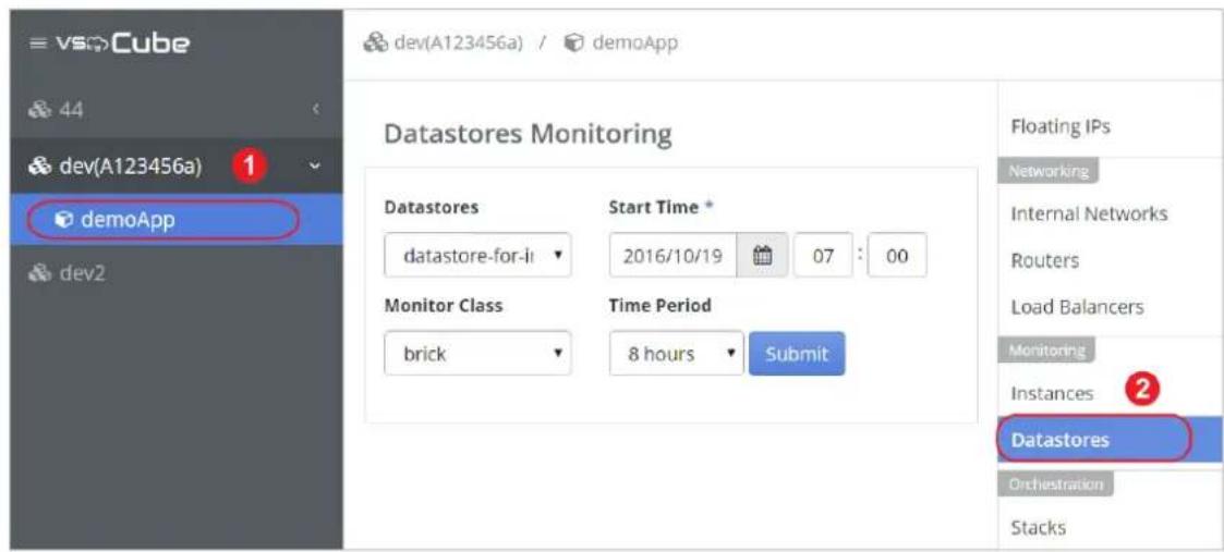
10. Chapter 10. Stack (Orchestraon)
You can orchestrate cloud applicaons by using templates in the Amazon Web Services (AWS) CloudFormaon template format or the nave OpenStack Heat Orchestraon Template (HOT) format. The templates enable the ecient creation of instances, oang IP addresses, volumes, security groups, and other resources. The resources are known as stacks.
These exible template languages enable applicaon developers to describe and automate the deployment of infrastructure, services, and applicaons. The templates enable createon of most OpenStack resource types, such as instances, oang IP addresses, volumes, security groups, and users. The resources, once created, are referred to as stacks.
Stack
A set of OpenStack resources created and managed by the Orchestraon service according to a given template (either an AWS CloudFormaon template or a Heat Orchestraon Template (HOT)).
Heat
This is an integrated project that aims to orchestrate mulple cloud applicaons for OpenStack.
Heat Orchestraon Template (HOT)
Heat input in the format nave to OpenStack.
10.1. Wring a Template
The template languages are described in the Template Guide in the Heat developer documentaon. The material in this secon was derived from the open-sourced documentaon for the OpenState website and modified slightly to suit our needs.
OpenStack template guide:
http://docs.openstack.org/developer/heat/template_guide/index.html
OpenStack Heat developer documentaon:
hp://docs.openstack.org/developer/heat/
Noce
Currently only templates in JSON format are supported in VSkyCube. Transfer the template to JSON format if it is in YAML format.
10.1.1. Basic Template
The basic template contains only a single resource denion using predened properes (along with the mandatory Heat template version tag). The example template below could be used to simply deploy a single compute instance. (See CODE C1)
{
    "heat_template_version": "2015-04-30",
    "description": "Simple template to deploy a single compute instance",
    "resources": {
    "my_instance": {
    "type": "OS::Nova::Server",
    "properties": {
    "key_name": "my_key",
    "image": "cirros",
    "flavor": "m1.tiny",
    "networks": [
    {
    "network": "int-netE"
    }
    ]
    }
    }
    }
}
Each HOT template has to include the heat_template_version key with a valid version of HOT, e.g. 2015-10-15 (see Heat template version for a list of all versions). While the descripon is oponal, it is good pracce to include some useful text that describes what you can do with the template.
Noce
About Heat template version, see
hp://docs.openstack.org/developer/heat/template_guide/hot_spec.html
The resources secon is required and must contain at least one resource denion. In the example above, a compute instance is dened with xed values for the 'key_name', 'image' and 'avor' parameters.
Note that all those elements, i.e. a key pair with the given name, the image and the avor have to exist in the VSkyCube environment where the template is used. Typically a template is made more easily reusable, though, by dening a set of input parameters instead of hard-coding such values.
10.1.2. Template Input Parameters
Input parameters dened in the parameters secon of a HOT template allow you to customize a template during deployment. For example, this allows for providing custom key pair names or image IDs to be used for a deployment. From a template author's perspective, this helps to make a template more easily reusable by avoiding hardcoded assumpons.
Noce
More informaon about parameters, see
hp://docs.openstack.org/developer/heat/template_guide/hot_spec.html
Scking to the example used above, it makes sense to allow you to provide their custom key pairs, provide their own image, and to select a avor and networks for the compute instance. This can be achieved by extending the initial template as follows: (see CODE C2)
{
    "heat_template_version": "2015-04-30",
    "description": "Simple template to deploy a single compute instance",
    "parameters": {
    "key_name": {
    "type": "string",
    "label": "Key Name",
    "description": "Name of keypair to inject into the server."
    },
    "image": {
    "type": "string",
    "label": "Image Name",
    "description": "Name of image to be used."
    },
    "flavor": {
    "type": "string",
    "label": "Instance Type",
    "description": "Type of instance (flavor) to be used."
    },
    "network": {
    "type": "string",
    "label": "Network Name",
    "description": "Name of network to create a port on."
    }
},
"resources": {
    "my_instance": {
    "type": "OS::Nova::Server",
    "properties": {
    "key_name": {"get_param": "key_name"},
    "image": {"get_param": "image"},
    "flavor": {"get_param": "flavor"},
    "networks": [
    {"network": {"get_param": "network"}
    ]
    }
    }
}
In the example above, four input parameters have been dened that have to be provided by the user upon deployment. The xed values for the respective resource properes have been replaced by references to the corresponding input parameters by means of the get_param funcon.
Noce
About get_param funcon, see secon intrinsic funcons in
hp://docs.openstack.org/developer/heat/template_guide/hot_spec.html
10.1.3. Template Environment
The environment aects the runme behavior of a template. It provides a way to override the resource implementaons and a mechanism to place parameters that the service needs. The environment is a JSON text le. You can dene values for the template arguments in an environment le: (see CODE C3)
{
    "parameters": {
    "key_name": "my_key",
    "image": "cirros",
    "flavor": "m1.tiny",
    "network": "int-netE"
    }
}
10.2. Launching and Previewing a Stack
There are 2 types of templates: templates with parameters and without parameters.
10.2.1. Template without Parameters
There are no parameters in the template. The value of resources is dened in the template. For example: CODE C1 in the previous chapter is a template without parameters.
10.2.2. Template with Parameters
The value of resources is in the template parameters and you need to specify the parameter values when using the template. The parameter values should be dened in the Environment.
For example, CODE C2 in previous chapter is a template with parameters and CODE C3 is the Environment.
Note
You can use CODE C1, C2 and C3 as sample code to launch or preview a stack.
However, remember to replace the values of resources and parameters with the real environment of your cluster.
The only dierence between launching and previewing is that Preview Stack will only simulate the execution of the stack according to the template you oered and will not take effect. Preview Stack is a good way to verify the template and parameters. The steps of launching and previewing stacks are the same.
Open the Launch Stack panel:
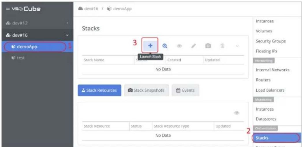
Open the Preview Stack panel:

Aer opening the panel, follow the steps below to launch or preview a stack.
- In the panel, you will see 2 parts as shown in the picture below.
A. Template Source/Template File
B. Environment Source/Environment File
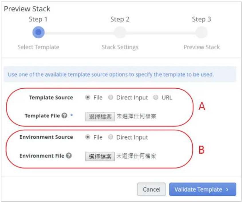
- Choose the source of your input, you can either upload a le or type your input directly into the text area. Check the content of the template before proceeding to the next step. If there are parameters in the Template File/Data, the relevant Environment File/Data should also be submied.
- In Stack Sengs, you have to specify: Stack Name, Creaon Timeout, and Rollback.
Creaon Time: Stack creaon meout in minutes.
Rollback: Enable/Disable rollback on create/update failure.
Stack Parameters: If there are parameters in the template, the value of parameters which the user input in the previous step will be displayed. Make sure all values are correct before proceeding to the next step.

- (For Preview Stack) Aer subming, the simulated data will be shown. The data will be cleared aer clicking the Close buon.
![Preview Stack Step 1 Select Template Step 2 Stack Settings Step 3 Preview Stack { "parameters": { "OS::project_id": "26a6f2065271435f894b7bafad7e9347", "OS::stack_id": "None", "OS::stack_name": "myStackWithoutParam" }, "id": "None", "description": "Simple template to deploy a single compute instance", "links": [ { "href": "http://angelaops:8004/v1/26a6f2065271435f894b7bafad7e9347/stack" "rel": "self" } ], "capabilities": [], "resources": [ {](/content/2026/06/1199685/images/79360425da08a7677224860f3e944f1f720c99947f0bc8169079264fdb231606.jpg)
- (For Launch Stack) Aer subming, the stack will be listed in the table.

10.3. Stack Acons
In this secon you will learn how to manage and control the stack with dierent acons.
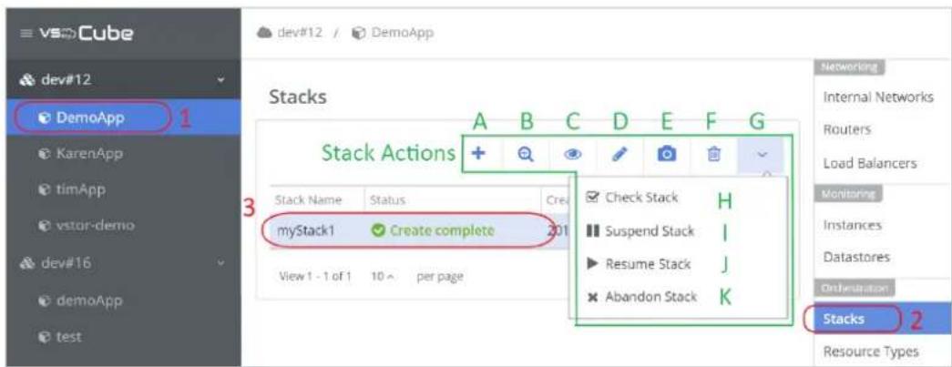
To locate Stacks service, follow the steps described in the above picture.
- Select the applicaon on the le sidebar.
- Click Stacks on the right menu.
- Click the row to select a stack.
Stack acon buons are listed on top of the table and introduced below from le to right.
-
- Launch Stack: To launch a stack, please refer to 10.2 Launching and Previewing a Stack.
- 🔒 Preview Stack: See buon A. Launch Stack.
- Stack Details: View the details of selected stacks.
-
Change Stack Template: To change stack with dierent template. All the resources in the stack will be replaced, this acon cannot be reversed.
-
Take Snapshot: Take a snapshot of current status for the selected stack. To manage the snapshot of the stack, please refer to 10.5 Stack Snapshots.
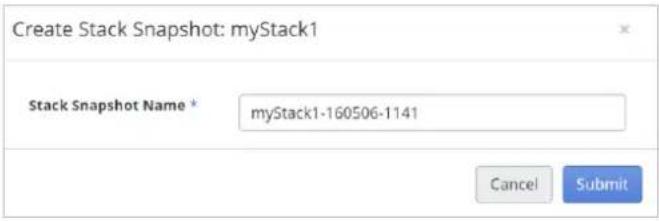
-
Delete Snapshot: Delete the selected snapshot.
-
▼ More: Click the down arrow icon to open the drop-down menu.
-
☑ Check Status: Click to check the status of stack.
-
III Suspend Stack: Suspend the execuon of a stack. All the resources of the stack will be suspended.
-
▶ Resume Stack: Resume the execuon of a stack.
-
✗ Abandon Stack: Stop and delete the stack conguraon but keep all the resources of the stack.
10.4. Stack Resources

Follow these steps numbered in the above picture.
-
Select the applicaon on the le sidebar.
-
Click Stacks on the right menu.
-
Click the Stack Resources tab.
-
Click the row to select a stack and the resources of the stack will be listed in the table below.
-
Click a row to select a resource.
-
Click the eye icon to view the details of the selected resource.
Noce
All the resources are controlled by the stack. Manually managing or operating the resources may cause unexpected errors and the stack may not work properly.
10.5. Stack Snapshots

Follow these steps numbered in the above picture.
- Select the applicaon on the le sidebar.
- Click Stacks on the right menu.
- Click the Stack Snapshots tab.
- Click a row to select a stack and the snapshots of the stack will be listed in the table below.
- Click the camera icon to take a snapshot of the selected stack. The stack name and a mestamp format posix will be used as the snapshot name. You can change the snapshot name.

- Click the row to select the snapshot. There are 3 buons on top of the table for snapshot management.
A. View Detail: View the details of the selected snapshot.
B. ☑ Restore Stack: Restore the stack with the selected snapshot.
C. Delete Stack Snapshot: Delete the selected snapshot.
10.6. Stack Events

Follow the steps described in the above picture.
- Select the applicaon on the le sidebar.
- Click Stacks on the right menu.
- Click the Events tab.
- Click a row to select a stack and the events of the stack will be listed in the table below.
- Click a row to select an event.
- Click the eye icon to view the details of the selected event.
10.7. Resource Types

Follow the steps described in the above picture. All the supported resource types are listed in the table. Click the eye icon to see the aributes and properes of the selected resource type.
11. Chapter 11. Upgrade
Use the informaon in this secon for cluster (VSkyCube) or portal (VSkyView) upgrades.
11.1. Cluster (VSkyCube) Upgrade
To upgrade a cluster, select the Cluster Upgrade opon in the Cluster-Related menu. You can upgrade a cluster when a new release is available through VSkyView. When you want to upgrade the cluster, every node must be upgraded to the same version. Therefore, if you want to perform the upgrade, make sure every node in the cluster is online.
There are two types of cluster upgrade, a major upgrade and a minor upgrade. Major upgrades will influence the cluster operaons, and all services will stop until the upgrade is nished. Yet a minor upgrade is done live. Services stay online. Please always wait for an upgrade to complete before aempng to perform any additional procedures or operaons, including another upgrade. The upgrade history will be recorded so you can check the details on the History tab.
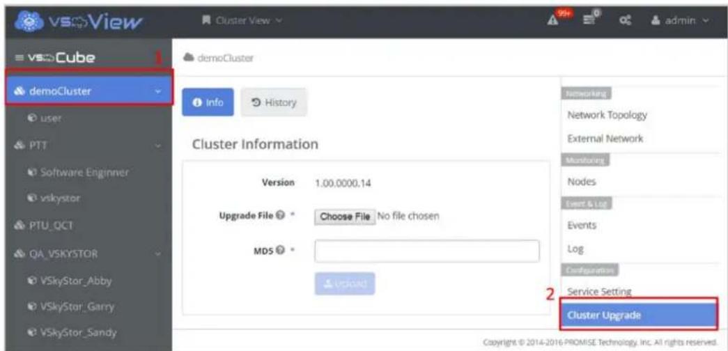
11.2. Portal (VSkyView) Upgrade
The Portal Info opon allows you to upload les for portal upgrade. You can update the portal version when a new release is available on the interface. The upgrade le is in the jar le format. You can also check the md5 checksum of the le before doing the upgrade.



- VSkyCube & VSkyView User Guide
- Contents
- Cluster Node CLI Tool.... 34
- Cluster Services.... 38
- Cluster High Availability 40
- Event and Log.... 45
- Chapter 5. Application Management.... 47
- Chapter 6. Virtual Machine Management .... 52
- Chapter 7. Networking....95
- Chapter 8. Storage ...... 138
- Volume 150
- Chapter 9. Monitoring.... 160
- Chapter 10. Stack (Orchestraon).... 162
- Chapter 11. Upgrade.... 175
- Chapter 1. Overview
- Chapter 2. VSkyView User Interface Introducon
- Start Using the VSkyView Management Portal
- Physical View
- VSkyView System Sengs
- User Management
- Email Server (SMTP) Conguraon
- Alert Email Conguraon
- VSkyView Logs
- VSkyView System Informaon
- Personal Sengs
- Edit Prole
- Change Password
- Sign Out
- Cluster View
- Summary
- Cluster Deployment
- Cluster Directory
- Cluster-Related Menu
- Applicaon
- Storage
- Compute
- Networking
- Monitoring
- Event & Log
- Conguraon
- Applicaon Directory
- Applicaon-Related Menu
- Orchestraon
- Chapter 3. Host Management
- Host Acons
- Add Host
- Edit Hosts
- Delete Hosts
- Obtain the IP Address of the VSkyCube Host
- Noce
- Chapter 4. Cluster Management
- Create a Cluster
- Step 1: Cluster Sengs
- Step 2: Select Hosts
- Name Network Interfaces IP Mask
- Step 3: Preview and Start Deploying the Cluster
- Network
- Trouble Shoong
- Q1. The node status shows Timeout during deployment.
- Q2. A warning message shows up at boong me; what should I do?
- Two Network Segment Interface Setng
- Cluster Management
- Register Cluster
- Unregister Cluster
- Add Hosts to the Selected Cluster
- Note
- Retry Failed Hosts
- Edit Cluster
- NOTICE
- Change Cluster Password
- Delete Cluster
- Reboot All Nodes
- Shut Down All Nodes
- Node Management
- Node Details
- Edit Node
- Retry Failed Host
- Delete Node
- Network Sengs
- Reboot Node
- Shut Down Node
- Change Node to Controller/Change Node to Worker
- Troubleshoong
- Node Deploy Logs
- Cluster Node CLI Tool
- Warning for Changing Node Network Setngs
- Transfer VIP via Node CLI
- Remove from Isolaon
- FAQ
- Cluster Services
- Cluster Service Sengs
- Cluster High Availability
- Cluster High Availability Requirements
- Cluster High Availability Scenarios
- Node Role: VIP Controller
- Node Role: Controller, Worker
- Workow of High Availability and Recovery (VIP Controller)
- Workow of High Availability and Recovery (Controller and Worker)
- Event and Log
- Email Nocaon
- Chapter 5. Applicaon Management
- Create an Applicaon
- Applicaon Wizard
- Exing the Applicaon Wizard
- Applicaon Acons
- Chapter 6. Virtual Machine Management
- Launch an Instance
- Selected Networks *
- Instance Boot Source
- Boot from image
- Boot from instance snapshot
- Boot from volume
- Boot from ISO (Linux)
- Boot from ISO (Windows)
- Instance Acons
- Accessing Instances
- Images
- Create Image
- Creang an Amazon Machine Image (AMI)
- AMI (Amazon Machine Image)
- AKI (Amazon Kernel Image)
- ARI (Amazon RAMDisk Image)
- Image Acons
- Image Life Cycle
- Flavors
- Create Flavor
- Delete Flavor
- Key Pairs
- cloud-init
- Create Key Pair
- Import Key Pair
- Delete Key Pair
- Security Groups
- Manage Security Group
- Set Up Security Group Rules for accessing Instances
- Resource Rao
- No Overprovisioning
- Medium Level of Overprovision
- High Level of Overprovision
- Floang IPs
- Associate Floang IP to Instance
- Manage Floang IP
- Chapter 7. Networking
- Glossary
- External Network
- Internal Network
- Subnet
- Router
- Network Topology
- Build a Basic Network Environment
- Preparaon
- Step Outline
- Part 1. External Network Conguraon
- Part 2. Create an Internal Network
- Part 3. Create a Router and Interface
- Network Wizard
- Manage External Network
- Manage Internal Networks
- Share Internal Network with Other Applicaons
- Create Internal Network
- Manage Subnets
- Ports
- Manage Routers and Interfaces
- Routers
- Use Ping on the Router to Verify the Network Connecon
- Interfaces
- External Gateway
- Internal Interface
- SNAT
- Create and Remove External Gateway
- Create Internal Interface and SNAT
- Stac Routes
- Load Balancer
- Build a Basic Load Balancer for a Website
- Step Outline:
- Step 1. Create a Load Balancer Pool
- Step 2. Create a VIP for the Pool
- Step 3. Launch Instances
- Step 4. Congure Security Group
- Step 5. Add the Members to the Pool
- Step 6. Setup a Sample Web Server
- Step 7. Associate a Floang IP Address to the VIP Port
- Step 8. Create a Health Monitor and Associate it with the Pool
- Step 9. Validate the Results
- Load Balancer Pool
- Round robin
- Source IP
- Least connecons
- VIP
- Session Persistence
- Member
- Health Monitor
- Chapter 8. Storage
- Physical Pool
- Add Physical Disks
- Cluster Storage
- Image Storage
- Create a Datastore for Image Storage
- Create a RAIN Datastore for Image Storage (Cluster HA)
- Compute Storage
- Applicaon Pool
- Applicaon Pool (App Pool)
- Create an Applicaon Pool
- Datastores
- Volume
- Datastore Properes and Hardware Requirements
- Disk Type
- Performance
- Redundancy (Fault Tolerance)
- - Regular
- - None
- Ulizaon
- - Thin-Provision
- - Tiering
- Cache
- Check Hardware Disk Resources
- Create Datastore
- Troubleshoong
- Volume
- Volumes
- Volume Snapshots
- Create Volume
- Aach a Volume to an Instance
- Volume Source
- No source, empty volume.
- Snapshot
- Image
- How to Check Volume Source aer Creaon
- Volume Acons
- Volume Snapshot
- Troubleshoong
- Chapter 9. Monitoring
- Nodes Monitoring
- Instance Monitoring
- Datastores Monitoring
- Chapter 10. Stack (Orchestraon)
- Stack
- Heat
- Heat Orchestraon Template (HOT)
- Wring a Template
- OpenStack template guide:
- OpenStack Heat developer documentaon:
- Basic Template
- Template Input Parameters
- Template Environment
- Launching and Previewing a Stack
- Template without Parameters
- Template with Parameters
- Open the Launch Stack panel:
- Open the Preview Stack panel:
- Stack Acons
- Stack Resources
- Stack Snapshots
- Stack Events
- Resource Types
- Chapter 11. Upgrade
- Cluster (VSkyCube) Upgrade
- Portal (VSkyView) Upgrade
Brand : Promise Technology
Model : VSkyCube
Category : NAS