
TREK-734 - Scale Advantech - Free user manual and instructions
Find the device manual for free TREK-734 Advantech in PDF.

| Product Type | RISC All-in-One Heavy Duty Mobile Data Terminal |
| Dimensions (W x H x D) | 250 x 175 x 47 mm (without IP54 cover); 250 x 175 x 95 mm (with IP54 cover) |
| Weight | 1.3 kg (2.86 lb) |
| Power Input | 9-32 VDC |
| Processor | Freescale ARM Cortex-A9 i.MX6 DualLite @ 1 GHz |
| Memory | 1 GB DDR3 (supports up to 2 GB) |
| Storage | 4 GB eMMC (supports up to 8 GB); 1 x Micro SD slot (externally accessible) |
| Operating System | Android 5.1.1 |
| Display | 8" TFT LCD, 1024 x 600, 750 nits, capacitive multitouch |
| Wireless Connectivity | WiFi 802.11 b/g/n, Bluetooth 4.0, GNSS (GPS, BD, GLONASS, Galileo), LTE (optional) |
| I/O Ports | 1 x CAN bus, 2 x RS-232, 1 x USB 2.0 host, 1 x mini USB, audio, CVBS, 6x DI/2x DO |
| Backup Battery (Optional) | 7.2 V, 2450 mAh, 2S1P |
| Operating Temperature | -20°C to 70°C (-4°F to 158°F) without backup battery |
| Storage Temperature | -30°C to 80°C (-22°F to 176°F) without battery |
| Environmental Protection | IP54 (with optional cover) |
| Shock & Vibration | MIL-STD-810G, SAE J1455 |
| Certifications | CE, FCC Class B, UL/cUL, CB, CCC, E-Mark |
| Warranty | 2 years |
Frequently Asked Questions - TREK-734 Advantech
User questions about TREK-734 Advantech
0 question about this device. Answer the ones you know or ask your own.
Ask a new question about this device
Download the instructions for your Scale in PDF format for free! Find your manual TREK-734 - Advantech and take your electronic device back in hand. On this page are published all the documents necessary for the use of your device. TREK-734 by Advantech.
USER MANUAL TREK-734 Advantech
natural_image
Illustration of four electronic circuit boards on a solid orange background, no text or symbols presentTREK-734
RISC All-in-One Heavy duty Mobile Data Terminal
Copyright
The documentation and the software included with this product are copyrighted 2017 by Advantech Co., Ltd. All rights are reserved. Advantech Co., Ltd. reserves the right to make improvements in the products described in this manual at any time without notice. No part of this manual may be reproduced, copied, translated or transmitted in any form or by any means without the prior written permission of Advantech Co., Ltd. Information provided in this manual is intended to be accurate and reliable. However, Advantech Co., Ltd. assumes no responsibility for its use, nor for any infringements of the rights of third parties, which may result from its use.
Acknowledgements
i.MX6 is trademarks of Freescale NXP.
Android is registered trademarks of Google LLC.
All other product names or trademarks are properties of their respective owners.
Product Warranty (2 years)
Advantech warrants to you, the original purchaser, that each of its products will be free from defects in materials and workmanship for two years from the date of purchase.
This warranty does not apply to any products which have been repaired or altered by persons other than repair personnel authorized by Advantech, or which have been subject to misuse, abuse, accident or improper installation. Advantech assumes no liability under the terms of this warranty as a consequence of such events.
Because of Advantech's high quality-control standards and rigorous testing, most of our customers never need to use our repair service. If an Advantech product is defective, it will be repaired or replaced at no charge during the warranty period. For out-of-warranty repairs, you will be billed according to the cost of replacement materials, service time and freight. Please consult your dealer for more details.
If you think you have a defective product, follow these steps:
- Collect all the information about the problem encountered. (For example, CPU speed, Advantech products used, other hardware and software used, etc.) Note anything abnormal and list any onscreen messages you get when the problem occurs.
- Call your dealer and describe the problem. Please have your manual, product, and any helpful information readily available.
- If your product is diagnosed as defective, obtain an RMA (return merchandize authorization) number from your dealer. This allows us to process your return more quickly.
- Carefully pack the defective product, a fully-completed Repair and Replacement Order Card and a photocopy proof of purchase date (such as your sales receipt) in a shippable container. A product returned without proof of the purchase date is not eligible for warranty service.
- Write the RMA number visibly on the outside of the package and ship it prepaid to your dealer.
Part No. Edition 2
Jan. 2018
Declaration of Conformity
CE
This product has passed the CE test for environmental specifications. Test conditions for passing included the equipment being operated within an industrial enclosure. In order to protect the product from being damaged by ESD (Electrostatic Discharge) and EMI leakage, we strongly recommend the use of CE-compliant industrial enclosure products.
FCC Class B
Note: This equipment has been tested and found to comply with the limits for a Class B digital device, pursuant to part 15 of the FCC Rules. These limits are designed to provide reasonable protection against harmful interference in a residential installation. This equipment generates, uses and can radiate radio frequency energy and, if not installed and used in accordance with the instructions, may cause harmful interference to radio communications. However, there is no guarantee that interference will not occur in a particular installation. If this equipment does cause harmful interference to radio or television reception, which can be determined by turning the equipment off and on, the user is encouraged to try to correct the interference by one or more of the following measures:
Reorient or relocate the receiving antenna
Increase the separation between the equipment and receiver.
Connect the equipment into an outlet on a circuit different from that to which the receiver is connected.
Consult the dealer or an experienced radio/TV technician for help.
This device complies with Part 15 FCC Rules.
Operation is subject to the following two conditions.
(1) This device may not cause harmful interference, and
(2) The device must accept any interference received, including interference may cause undesired operation.
FCC Caution:
Any changes or modifications not expressly approved by the party responsible for compliance could void the user's authority to operate this equipment.
FCC RF Radiation Exposure Statement :
This device meets the government's requirements for exposure to radio waves.
This device is designed and manufactured not to exceed the emission limits for exposure to radio frequency(RF) energy set by the Federal Communications Commission of the U.S. Government.
This device complies with FCC radiation exposure limits set forth for an uncontrolled environment. In order to avoid the possibility of exceeding the FCC radio frequency exposure limits, human proximity to the antenna shall not be less than 20cm (8 inches) during normal operation.
Changes or modifications not expressly approved by the party responsible for compliance could void the user's authority to operate the equipment.
Technical Support and Assistance
- Visit the Advantech web site at http://support.advantech.com where you can find the latest information about the product.
- Contact your distributor, sales representative, or Advantech's customer service center for technical support if you need additional assistance. Please have the following information ready before you call:
– Product name and serial number
– Description of your peripheral attachments
– Description of your software (operating system, version, application software, etc.)
— A complete description of the problem
– The exact wording of any error messages
Warnings, Cautions and Notes
Warning! Warnings indicate conditions, which if not observed, can cause personal

injury!
Caution! Cautions are included to help you avoid damaging hardware or losing data. e.g.

There is a danger of a new battery exploding if it is incorrectly installed. Do not attempt to recharge, force open, or heat the battery. Replace the battery only with the same or equivalent type recommended by the manufacturer. Discard used batteries according to the manufacturer's instructions.
Note! Notes provide optional additional information.

Document Feedback
To assist us in making improvements to this manual, we would welcome comments and constructive criticism. Please send all such - in writing to: support@advantech.com
Packing List
Before setting up the system, check that the items listed below are included and in good condition. If any item does not accord with the table, please contact your dealer immediately.
| Part number | Description | Q`ty |
| TREK-734C | TREK-734 Computer | 1 |
| 1700019031 | Power cable (2M) | 1 |
Ordering Information
P/N Description
| TREK-734C-WBADA0E | TREK-734 I. MX6 1GB,4GB , Android5.1 WiFi only |
| TREK-734C-LWBADA1E | TREK-734 IMX6,2GB,8GB And.5.1 LTE EU EC-25E Int. |
| TREK-734C-LWBADB1E | TREK-734 IMX6,2GB,8GB And.5.1, LTE NA EC-25A Ext. |
| TREK-734C-LWBADC0E | TREK-734 I. MX6 1GB,4GB , Android5.1, Huawei 909s |
Optional Accessories
P/N Description
| 1760002560-01 | Backup Baery pack 7.2V 2450mAh 2S1P |
| TREK-734-IP000 | IP54-rated I/O Cover |
| 1700026766-01 | High Density Connector Cable |
| 1750008571-01 | WLAN/BT external antenna (TNC) |
| 1750008570-01 | WWAN/GPS external antenna (TNC) |
Safety Instructions
- Read these safety instructions carefully.
- Keep this User Manual for later reference.
- Disconnect this equipment from any AC outlet before cleaning. Use a damp cloth. Do not use liquid or spray detergents for cleaning.
- For plug-in equipment, the power outlet socket must be located near the equipment and must be easily accessible.
- Keep this equipment away from humidity.
- Put this equipment on a reliable surface during installation. Dropping it or letting it fall may cause damage.
- Do not leave this equipment in an environment unconditioned where the storage temperature under -30^ C ( -22^ F) or above 80^ C ( 176^ F), it may damage the equipment. Operating temperature: -20^ C\~ 70^ C without battery.
- Do not operate this equipment in an environment temperature may over 70^ C( 158^ F). The surface temperature of plastic chassis may be hot.
- Make sure the voltage of the power source is correct before connecting the equipment to the power outlet.
- Position the power cord so that people cannot step on it. Do not place anything over the power cord. The voltage and current rating of the cord should be greater than the voltage and current rating marked on the product.
- All cautions and warnings on the equipment should be noted.
- If the equipment is not used for a long time, disconnect it from the power source to avoid damage by transient overvoltage.
- Never pour any liquid into an opening. This may cause fire or electrical shock.
- Never open the equipment. For safety reasons, the equipment should be opened only by qualified service personnel.
- If one of the following situations arises, get the equipment checked by service personnel:
„ The power cord or plug is damaged.
„ Liquid has penetrated into the equipment.
„ The equipment has been exposed to moisture.
The equipment does not work well, or you cannot get it to work according to the user's manual.
„ The equipment has been dropped and damaged.
„ The equipment has obvious signs of breakage.
- CAUTION: The computer is provided with a battery-powered real-time clock circuit. There is a danger of explosion if battery is incorrectly replaced. Replace
only with same or equivalent type recommended by the manufacture. Discard used batteries according to the manufacturers instructions.
- This device complies with Part 15 of the FCC rules. Operation is subject to the following two conditions:
(1) this device may not cause harmful interference, and (2) this device must accept any interference received, including interference that may cause undesired operation. - CAUTION: Always completely disconnect the power cord from your chassis whenever you work with the hardware. Do not make connections while the power is on. Sensitive electronic components can be damaged by sudden power surges.
- CAUTION: Always ground yourself to remove any static charge before touching the motherboard, backplane, or add-on cards. Modern electronic devices are very sensitive to static electric charges. As a safety precaution, use a grounding wrist strap at all times. Place all electronic components on a static-dissipative surface or in a static-shielded bag when they are not in the chassis.
- CAUTION: Any unverified component could cause unexpected damage. To ensure the correct installation, please always use the components (ex. screws) provided with the accessory box.
Safety Precaution - Static Electricity
Follow these simple precautions to protect yourself from harm and the products from damage.
To avoid electrical shock, always disconnect the power from your PC chassis before you work on it. Don't touch any components on the mainboard or other cards while the system is on.
„ Disconnect power before making any configuration changes. The sudden rush of power as you connect a jumper or install a card may damage sensitive electronic components.
This product is intended to be supplied by a Listed DC power source, rated 9\~32Vdc, 10A maximum and Tma 55 degree C, if need further assistance with purchasing the DC power source, please contact Advantech for further information.
Warning!

- Input voltage rated: 9 \~ 32 Vdc.
- Transport: carry the unit with both hands and handle with care.
- Maintenance: to properly maintain and clean the surfaces, use only approved products or clean with a dry applicator.
- SD/SIM card: Turn off the power before inserting or removing the storage cards.
Contents
Chapter 1 General Information ....1
1.1 Introduction 2
1.2 General Specifications .... 4
1.3 Dimensions 5
Figure 1.1 TREK-734 dimensions....5
Chapter 2 System Setup ....7
2.1 A Quick Tour of the TREK-734 Computer....8
Figure 2.1 Front view of TREK-734 8
Figure 2.2 Rear view of TREK-734 8
2.2 Installation Procedures....9
2.2.1 Install SIM card & Storage card 9
Table 2.1: Install SIM card & Micro SD Card ......9
2.2.2 Connect Power 9
Figure 2.3 Power connector outlook....9
Table 2.2: Pin Definition of Power Connector.... 10
Figure 2.4 Power connector photo 10
Chapter 3 I/O connectors Pin assignments.....28
3.1 I/O Connectors Pin Assignment....28
3.3.1 Power Connector....28\~29
3.3.2 High Density Connector....30
3.3.2.1 High Density Cable....31
3.3.3 USB Connector....32
3.3.4 Mini USB Connector (Rear side)....32
Chapter 4 Software Demo Utility Setup....34
4.1 MRM SDK Package Contents & Overview....34\~36
4.2 How MRM SDK works....36
4.3 Installation of the MRM SDK....37\~46
4.4 Install Prebuilt Sample Apps....47
4.5 IVCP Demonstration....47
4.5.1 Firmware....47
4.5.2 Power Management....47 \~ 49
4.5.3 Battery....51
4.5.4 Alarm....51
4.5.5 Watchdog....52
4.5.6 Digital IO....53
4.5.7 Peripheral Control....53
4.5.8 Storage....54
4.5.9 G Sensor....55
4.5.10 G Sensor Alarm....55
4.5.11 P Sensor....56
4.5.12 Hotkey....56\~57
4.6 VCIL Demonstration....57
4.6.1 CAN....58\~59
4.6.2 CAN Filter....60
4.6.3 J1939....60
4.6.4 J1939 Config....61
4.6.5 J1939 Filter....62
4.6.6 OBD2....63
4.6.7 OBD2 Filter....65
4.6.8 J1708....66
4.6.9 J1708 Filter....67
4.6.10 J1587....68
4.6.11 J1587 Filter....68
Appendix A Peripheral Installaon....70
A-1 Installing the Backup Battery....70\~74
A-2 Installing the RAM mount kit....74
A-3 Installing the IP54 I/O cover....75\~77
A-4 Installing the HDC cable 78\~79
Chapter 1
General Information
This chapter gives background information on the TREK-734 Computer
Sections include:
Introduction
„ General Specifications
„ Dimensions
1.1 Introduction
TREK-734 is a RISC-based open plaorm all-in-one light-duty mobile data terminal equipped with an 8" display, Freescale ARM® Cortex™-A9 i.MX 6 Dual lite processor, Android 5.1 OS, 2GB memory and LTE networking capabilities to enable high performance compung for eet management applicaons. LTE capabilities transform the terminal into a wireless network hub that supports WiFi, BT, and GPS communicaon to facilitate locaon tracking and route opmizaon. The built-in backup baery ensures an uninterruptable power supply by providing up to 30 minutes of emergency power in the event of a power failure. Cered to MIL-STD-810G standards for vibraon tolerance. Moreover, three external antenna ports are provided for enhanced network communicaon in order to eecvely support crical outdoor applicaons.
1.2 General Specifications
Features
- Freescale ARM® Cortex™-A9 i.MX 6 Dual lite processor with Android 5.1.
● Rich I/O connectors designed on top of rear side for easy system integraon.
● 2 front side speakers make volume louder in real applicaon environment.
● Built-in LTE/GNSS/WiFi/BT for data communicaon.
● Advanced Shock & an-vibraon cered by MIL-STD-810G.
● Advanced Android SDK, test utility for customer evaluang.
Specifications
| System | Processor | Freescale ARM® CortexTM-A9 i.MX 6DualLite (1 GHz) |
| Memory | 1 GB DDR3 (supports up to 2 GB) | |
| Storage | 4 GB onboard eMMC (supports up to 8 GB)1 x Micro SD slot (externally accessible) | |
| Watchdog | Yes | |
| RTC | Yes | |
| O.S | Android 5.1.1 | |
| RF | WiFi | IEEE 802.11 b/g/n |
| Bluetooth | Bluetooth V4.0 | |
| GNSS | u-blox MAX-M8Q (GPS, BD, GLONASS, Galileo) | |
| WWAN | LTE, HSPA+, GSM/GPRS/EDGE, WCDMA | |
| Voice call | N/A | |
| Wake-on-WWAN | N/A | |
| SIM | 1 SIM slot | |
| External Antenna | 1 x WLAN, 1 x WWAN, 1 x GPS (TNC type) | |
| Display | Size/Type | 8" (16:10) TFT LCD |
| Max. Resoluon | 1024 x 600 | |
| Brightness (cd/m2) | 750 nits | |
| Viewing Angle (R/L/B/T) | 70/80/80/80 | |
| Backlight Life | 20,000 hrs | |
| Touchscreen | Capacive (mul-touch) | |
| Brightness Control | Light sensor for automac dimming | |
| Funcon Key | 5 x programmable funcon keys with green LED backlight | |
| I/O | I/O Port(via high-density connector) | 1 x CAN bus (supports raw CAN, J1939, OBD-II/ISO 15765) (via high-density connector) |
| Generic I/O Port(via high-density connector) | 4 x Isolated DI/2 x DO1 x 4-wire RS-232, 1 x 2-wire RS-2321 x CVBS-In1 x Mic-In1 x Line-In (R & L)1 x Line-Out (R & L)1 x USB2.0 Type A host | |
| Standard I/O Port | 1 x USB 2.0 host @ R; mini USB debugging (5 pin)1 x USB 2.0 client @ R; USB type A host (4 pin) | |
| Indicator | 1x LED (Power) | |
| Power | Power Buon | Yes |
| Reset | Yes | |
| Input Voltage | 9-32V DC | |
| Backup Baery(Oponal) | 7.2 V 2450 mAh 2S1P | |
| Mechanical | Dimensions (W x H x D) | 250 x 175 x 95 mm (9.84 x 6.88 x 3.74") with IP-rated I/O cover250 x 175 x 47 mm (9.84 x 6.88 x 1.85") |
| Weight | 1.3 kg (2.86 lb) | |
| Environment | IP Rang | IP54 |
| Regulaon | E-Mark, ISO 7637-2, SAE J1455, SAE J1113 | |
| EMC | CE,FCC | |
| Safety | UL/cUL, CB, CCC | |
| Operang Temperature | -20°C ~ 70°C (-4°F ~ 158°F) without backup baery | |
| Storage Temperature | -30°C ~ 80°C (-22°F ~ 176°F) without baery | |
| Shock/Vibraon | MIL-STD-810G, SAE J1455 |
1.3 Dimensions
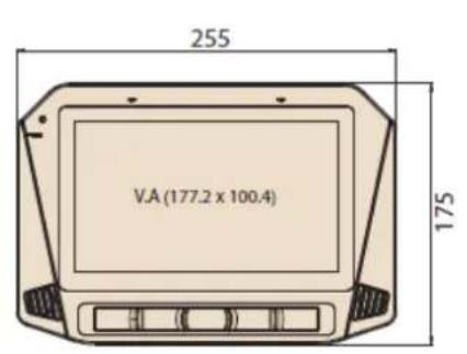
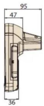

Figure 1.1 TREK-734 dimensions
Chapter 2
System Setup
This chapter details system setup on TREK-734
Sections include:
A Quick Tour of the Computer Box
Installation Procedures
2.1 A Quick Tour of the TREK-734 Computer
Before starting to set up TREK-734, take a moment to become familiar with the locations and functions of the connectors and ports, which are illustrated in the figures below.

Figure 2.1 Front view of TREK-734
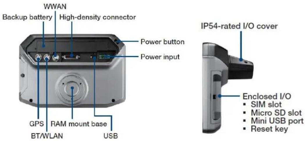
Figure 2.2 Rear view of TREK-734
2.2 Installation Procedures
2.2.1 Installing SIM car & Storage card
Remove enclosed I/O door screw and can install SIM Card & Micro SD card directly.
- Remove side I/O door

natural_image
Close-up of a hand pressing a metallic mechanical component with a small screw (no visible text or symbols)- Install SIM card or Micro SD card
natural_image
Interior view of a device showing a rear panel with a green card and USB port, no visible text or symbols on the main body.Figure 2.3 Installing SIM card & Storage card
2.2.2 Connecting Power
Connect the three pin waterproof power cord to the DC inlet of the Computing Box. On the open-wire end, one pin is reserved for positive voltage and is marked, "+"; one pin is reserved for ground and is marked, "-"; and, one pin is reserved for the ignition signal with an "ignition" mark.
Note!
Ignition on/off setting: The TREK-734 supports an ignition on/off function so that you can power on/off the TREK-734 via the ignition signal/voltage and connect the TREK-734 ignition switch.
Table 2.1: Pin Definition of Power Cord
| Pin | Definition | Color |
| 1 | - | Black |
| 2 | + | Red |
| 3 | Ignition | Orange |
2.2.2 Power Connector
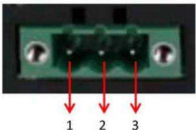
Figure 2.6 Power connector outlook
Table 2.2: Power connector
| Pin | Signal | Pin | Signal |
| 1 | Ground | 2 | Power input(9~32VDC) |
| 3 | Acc ignition input |
Chapter 3
I/O Connectors
This chapter explains how to set up the Computing Box hardware, including instructions on setting. Sections include:
■ I/O connectors pin assignment
3.1 I/O Connectors Pin Assignment
3.3.1 Power connector
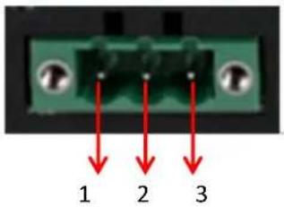
Table 3.1: Power connector
| Pin | Signal | Pin | Signal |
| 1 | Ground | 2 | Power input(9~32VDC) |
| 3 | Acc ignition input |
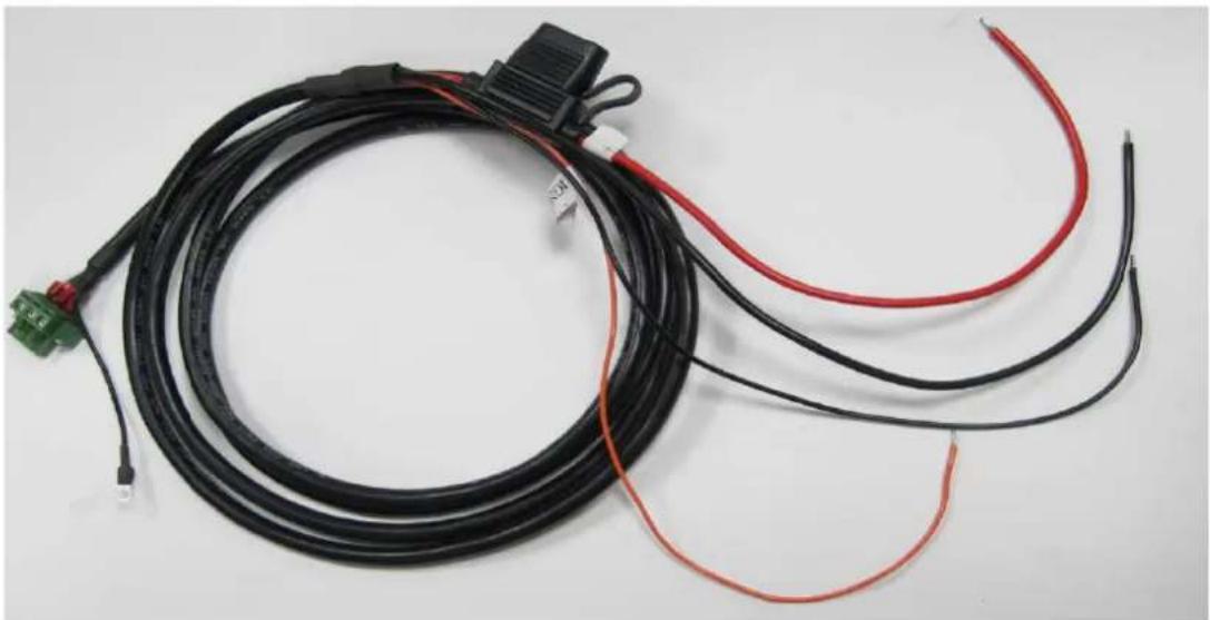
3.3.1.1 Power in Jack Cable
natural_image
Coiled black and red electrical wires with connectors, no visible text or symbolsPIN Signal Depiction
1 Power Ground
2 Power Input (9 \~ 32 VDC)
3 Acc Ignition Input
Shield Ground
Fuse Spec: 58V/10A*1
Cable /Label

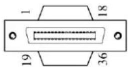
3.3.2 High Density Connector
1 GND 19 GND_CODEC
2 RS232 RTS1 HD 20 MIC_IN1
3 RS232 CTS1 HD 21 LINE_IN_P
4 RS232 TX1 HD 22 LINE_IN_N
5 RS232_RX1_HD 23 LINE_OUT_R
6 RS232_TX2_HD 24 LINE_OUT_L
7 RS232_RX2_HD 25 ISO_DO_DRAIN1
8 RS-232_DCD2_HD 26 ISO_DO_DRAIN2
9 CVBS_HD 27 ISO_DI_1
10 GND 28 ISO_DI_2
11 USB_HD_DP_H 29 ISO_DI_3
12 USB_HD_DN_H 30 ISO_DI_4
| 13 | GND | 31 | ISO_DI_5 |
| 14 | +V5_HD_USB | 32 | ISO_DI_6 |
| 15 | GND | 33 | ISO_GND |
| 16 | GND | 34 | GND |
| 17 | +12V_HD_HD1 | 35 | CAN_H_R |
| 18 | +12V_HD_HD1 | 36 | CAN_L_R |
3.3.2.1 High density cable
36Pin connector cable pin dene
| Pin number | Pin name |
| 1 | GND_RS12 |
| 2 | RS232_RTS1_HD |
| 3 | RS232_CTS1_HD |
| 4 | RS232_TX1_HD |
| 5 | RS232_RX1_HD |
| 6 | RS232_TX2_HD |
| 7 | RS232_RX2_HD |
| 8 | RS-232_DCD2_HD |
| 9 | CVBS_HD |
| 10 | GND_CVBS |
| 11 | USB_HD_DP_H |
| 12 | USB_HD_DN_H |
| 13 | GND_USB |
| 14 | +V5_HD_USB |
| 15 | GND_12V |
| 16 | GND_12V |
| 17 | +12V_HD_HD1 |
| 18 | +12V_HD_HD1 |
| 19 | GND_CODEC |
| 20 | MIC_IN1 |
| 21 | LINE_IN_P |
| 22 | LINE_IN_N |
| 23 | LINE_OUT_R |
| 24 | LINE_OUT_L |
| 25 | ISO_DO_DRAIN1 |
| 26 | ISO_DO_DRAIN2 |
| 27 | ISO_DI_1 |
| 28 | ISO_DI_2 |
| 29 | ISO_DI_3 |
| 30 | ISO_DI_4 |
| 31 | ISO_DI_5 |
| 32 | ISO_DI_6 |
| 33 | ISO_GND |
| 34 | GND_CAN |
| 35 | CAN_H_R |
| 36 | CAN_L_R |
High Density Cable Layout
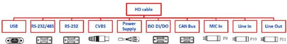
flowchart
graph TD
    A["HD cable"] --> B["USB"]
    A --> C["RS-232/485"]
    A --> D["RS-232"]
    A --> E["CVBS"]
    A --> F["Power Supply"]
    A --> G["ISO DI/DO"]
    A --> H["CAN Bus"]
    A --> I["MIC In"]
    A --> J["Line In"]
    A --> K["Line Out"]
3.3.3 USB Connector
Table 3. : USB Connector
| Pin | Signal Depiction |
| 1 | Vcc |
| 2 | USB_Data- |
| 3 | USB_Data+ |
| 4 | GND |
Chapter 4
Software Demo Utility Setup
This chapter explains the software demo utility for TREK-734
Sections include:
„Introduction
„ How to Set up Demo Utility
4.1 MRM SDK Package Contents & Overview
Advantech has developed demo utilities based on Advantech provided SDK APIs to let user test the functions on TREK-734. This document describes the usage of each demo utilities and also provide a basic concept of the application development on TREK-734.
For technical support, contact Advantech application engineers worldwide. For news updates, please visit our website : www.advantech.com and MRM forum :
http://mrmforum.advantech.com/index.aspx
The MRM SDK package contains the following contents:
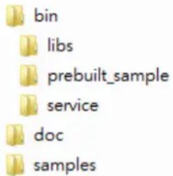
The description of each of the folder at the top level is listed below:
| Files/Directories | Description |
| bin/library/ | The Java library and native library files. These libraries should be imported in to your APP project. |
| bin/service/ | The MRM service APK file. The service APK file must be installed into your device before running your APP or prebuilt sample APPs. |
| bin/prebuilt_sample/ | The prebuilt APK files of sample codes. |
| doc | The Documents. |
| samples | The sample code. |
The MRM (Mobile Resource Management) SDK is a set of software libraries which provides APIs for controlling various functions of the target device.
The following figure describes the software stack of MRM SDK:

flowchart
graph TD
    A["Application"] --> B["IVCP"]
    A --> C["SDP"]
    A --> D["VCIL"]
    B --> E["IVCP SERVICE"]
    C --> F["SDP SERVICE"]
    D --> G["VCIL"]
    E --> H["OS / Device Drivers"]
    F --> I["OS / Device Drivers"]
    style A fill:#f9f,stroke:#333
    style B fill:#ccf,stroke:#333
    style C fill:#cfc,stroke:#333
    style D fill:#fcc,stroke:#333
4 MRM SDK is composed of the following function domains:
• IVCP (Intelligent Vehicle Co-Processor)
A VPM(Vehicle Power Management) MCU(Micro Controller Unit) is embedded in the device, which controls the power status of device and peripheral devices such as G-Sensor and P-Sensors.
The IVCP function domain is designed in client-service architecture. The IVCP Service acts as a proxy to access the VPM MCU and is able to serve multiple APP processes simultaneously. In your APP, you can use the IVCP APIs exported in the MRM Client APIs Library to communicate with the IVCP service.
IVCP Service Client API Modules:
- Firmware APIs - Get VPM MCU firmware version. Save/Load default settings
Power Management APIs - VPM related functions. ex: boot control, Ignition control, event delay adjustments, low battery protection and etc.
○ Battery APIs - Backup battery related information and functions - Alarm APIs - Internal RTC time setting and device alarm wakeup related functions.
○ Watchdog APIs - Watch dog functions. - Peripheral Control APIs - Power status management of peripheral devices.
○ Storage APIs - Internal EEPROM storage access. - G Sensor APIs - Access G sensor data. G sensor related settings.
- G Sensor Alarm APIs - G sensor device wakeup functions.
- P Sensor APIs - Access P sensor data.
• SDP (Smart Display Panel)
Depends on the specific device spec, the device may bundle with a smart display panel module. The smart display panel module is embedded with a MCU to control functions of the module. Similar with IVCP function domain, the SDP function domain is also designed in client-service architecture. You can use the SDP APIs exported in the MRM Client APIs Library to communicate with the SDP service.
SDP Service Client API Modules:
- Firmware APIs - Get SDP MCU firmware version. Save/Load default settings
- Backlight APIs - Configure brightness of smart display.
- Sensor APIs - Access sensor on smart display
○ Hotkey APIs - hotkeys related settings. - Speaker API - Speaker related settings
○ USB API - USB port related settings
• VCIL (Vehicle Communication Interface Layer)
A VCIM(Vehicle Communication Interface Module) MCU is embedded in the device for controlling the vehicle communication protocols (e.g. CAN, J1939, OBD2, J1708, J1587). For the performance considerations, the VCIL function domain is designed in form of libraries, You can use the VCIL APIs exported in the VCIL API Library to control the MCU directly. For VCIL does not have service layer, the VCIL API Library does NOT support multi-process access.
VCIL API Modules:
- VCIL APIs - Get VCIL MCU firmware version. Physical port protocol settings.
- CAN APIs - Read / write data with CAN protocol.
- J1939 APIs - Read / write data with J1939 protocol.
- OBD2 APIs - Read / write data with OBD2 protocol.
- J1708 APIs - Read / write data with J1708 protocol.
- J1587 APIs - Read / write data with J1587 protocol.
4.2 How MRM SDK Works
IVCP and SDP functions in the MRM SDK for Android is designed in client-service architecture.
To make your APP work with the MRM services to control the device you must first include the Service Client API library into you APP project. Before calling APIs to control the device, you must first "bind" you APP process to the MRM service processes. After binding is done, you can then call the IVCP, SDP APIs to communicate with the services. The MRM services act as
proxies for client APP to access the hardware functions.
Due to the nature of client-service structure, the MRM SDK for Android supports multi-processes access. It is available for the services to serve multiple application processes at the same time. The hardware resources are managed by the services and the client application does not need to worry about hardware resource occupation.
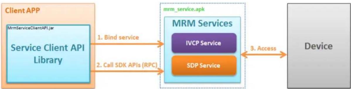
flowchart
graph LR
    A["Client APP"] -->|1. Bind service| B["MRM Services"]
    A -->|2. Call SDK APIs (RPC)| B
    B -->|3. Access| C["Device"]
    D["MrmServiceClientAPI.jar"] --> A
    E["Service Client API Library"] --> A
    F["mrm_service.apk"] --> B
    G["IVCP Service"] --> B
    H["SDP Service"] --> B
VCIL functions in the MRM SDK for Android is designed in form of libraries.
Before calling APIs to control the device, you must first call the initialization API to make the VCIM MCU ready to work. After initialization is done, you can then call the VCIL APIs to do operations of vehicle protocols.
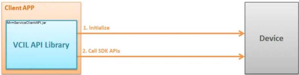
flowchart
graph LR
    A["Client APP"] -->|1. Initialize| B["Device"]
    A -->|2. Call SDK APIs| B
    A --> C["MrmServiceClientAPI.jar"]
    C --> D["VCIL API Library"]
4.3 Installation of the MRM SDK
You can install SDK(MRM Services) to your device by follow the steps below
1. Unzip the SDK package
Extract the SDK package zip file with password.
The password is same as the filename.
2. Install MRM Services (mrm\_service.apk)
( NOTE: This step is only necessary for IVCP and SDP function. You can skip this step if you only need VCIL functions )
Connect device to you computer with ADB.
Execute the script install_mrm_service.bat in [SDK_Pacakge]/bin/
The script will execute the following ADB command:
adb install -r .\mrm_service.apk
After installed, you will get the following package in your devices
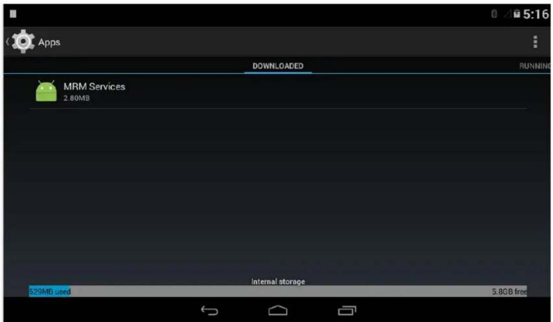
There will also be an MRM Service Console APP named "MRM" in the APP list. This is a utility for testing MRM Services and checking the basic information.

natural_image
Green Android robot logo with 'MRM' text below (no additional symbols or text)| MRM Control Panel | |
| SDK INFORMATION | |
| MRM SDK ver. | 4.0.1.0 |
| SYSTEM INFORMATION | |
| OS image ver. | dmsst05_6dq-eng 4.4.2 1.0.0-rc3 eng.root.20150925.152917 dev-keys |
| VPM FW ver. | 000.091 |
| MRM SERVICE STATUS | |
| IVCP Service | RUNNING(PID = 14889) |
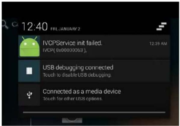
When MRM is launched, it will try to bind all MRM services. The MRM Services will be started and initialize related hardware resources.
If initialization failed, you can get message with error code in the notification area (drag down from left top of screen).

In the MRM, the service status will should be shown with the service process ID. The status will be one of the followings:
○ RUNNING
■ Service process is working correctly.
ex:
IVCP Service
RUNNING (PID = 3215)
○ NOT\_INITIALIZED
■ Service process exists but the hardware resources can not be initialized. In this status, the IVCP APIs can not work properly.
- You can find the error code message in the notification area.
ex:
IVCP Service
NOT_INITIALIZED (PID = 4305)
- UNKNOWN
■ Service process exists but the initialization status can not be confirmed.
- The error code will be also shown. (For the definition of error codes, please refer to the IVCP, VCIL, SDP User Manual)
ex:
IVCP Service
UNKNOWN (ERR-0x10200005) (PID = 5290)
- STOP
■ Service process does not exist.
ex:
IVCP Service
STOP
3. Import MRM Service Client APIs Library
( NOTE: This step is only necessary for IVCP and SDP function. You can skip this step if you only need VCIL functions )
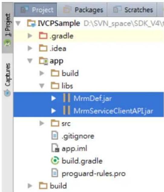
To access MRM Service from your APP, you must import the MRM Service Client API lib into you project.
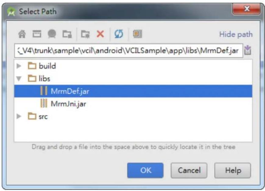
Please find the MrmServiceClientAPI.jar and MrmDef.jar in the MRM SDK package. Copy the libraries to the directory /[Module Name]/libs/ in you Android Studio project (the default module name might be "app").
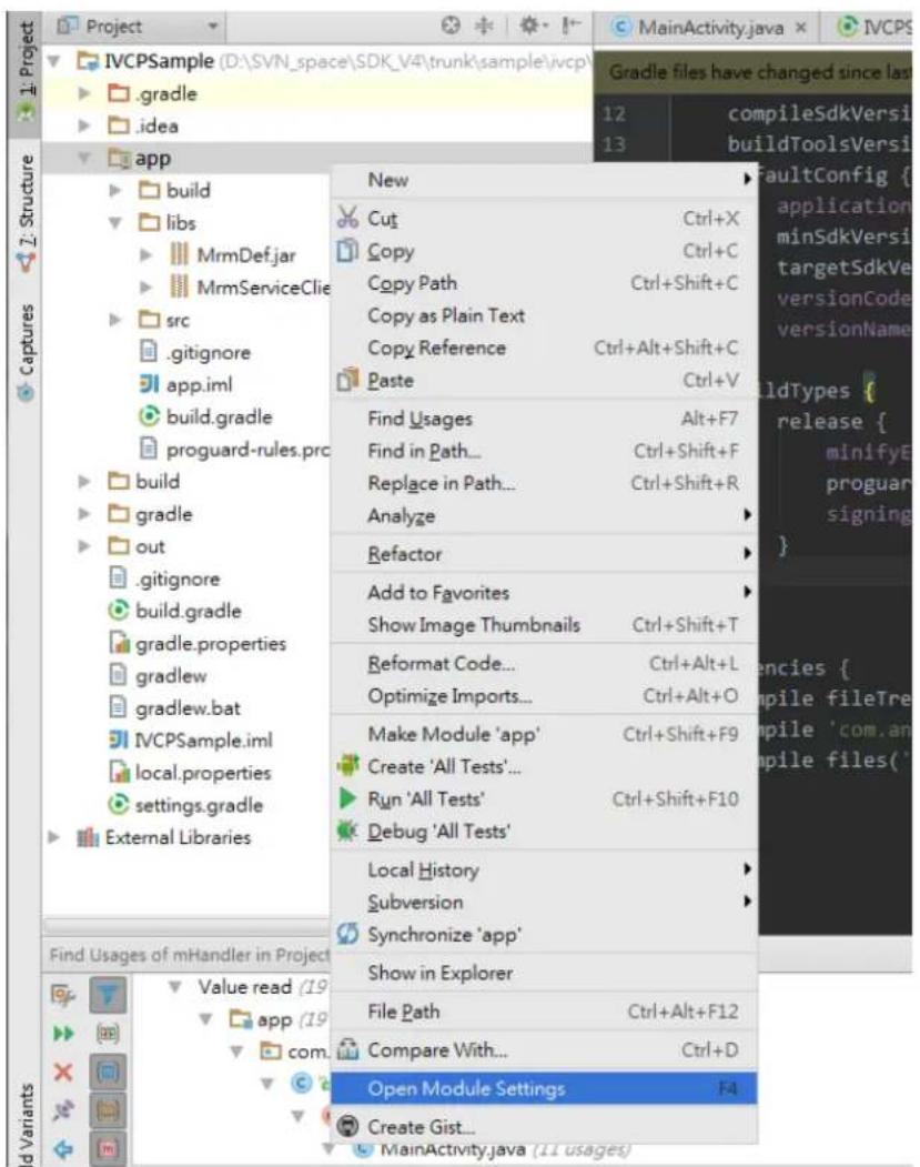
Then import the libraries by following the steps below:
- Right click on you APP module. Click "Open module settings"
- Click the "Dependency" tab. Then click "+" -> "File dependency"
![Project Structure + - Properties Signing Flavors Build Types Dependencies SDK Location Project Developer Services Ads Analytics Authentication Notifications Modules app Scope [include=[*jor], dir=1lbs] m com.android.support.appcompat-v7:22.0.0 Compile Compile OK Cancel m 1 Library dependency 2 File dependency 3 Module dependency](/content/2026/06/1199664/images/c100be609e64c33f88c83bb891c674f2b5a3e922133a975670cc5a7107e71717.jpg)
- Select the lib file.

- Repeat the above steps to add all libs and you will see all libs are added to the list.
![Project Structure + - Properties Signing Flavors Build Types Dependencies SDK Location Project Developer Services Ads Analytics Authentication Notifications Modules app {include=[*.jar], dir=libs} m com.android.support.appcompat-v7:22.0.0 Libs/MmmServiceClientAFLjar Libs/MmmDef.jar Scope Compile Compile Compile Compile OK Cancel](/content/2026/06/1199664/images/49c52f34a418610a1e7566d9d2f3ea9430308b48f52bd779105a38baa38df857.jpg)
1. Import VCIL APIs Library
( NOTE: This step is only necessary for VCIL functions )
To access VCIL functions from your APP, you must import the VCIL libraries into your project.
Please find the MrmJni.jar, MrmDef.jar and jniLibs/ folder in the MRM SDK package.
Copy the MrmJni.jar, MrmDef.jar to the directory /[Module Name]/libs/ in your Android Studio project (the default module name might be "app") and copy the jniLibs/ folder to the directory /[Module Name]/src/main/.

Then import the Java libraries by following the steps below:
- Right click on you APP module. Click "Open module settings"

- Click the "Dependency" tab. Then click "+" -> "File dependency"
![Project Structure + - Properties Signing Flavors Build Types Dependencies SDK Location Project Developer Services Ads Authentication Notifications Modules app {include=[*jar], dir=libs} m junit:junit:4.12 m com.android.support.appcompat-v7:22.2.1 Scope Compile Test compile Compile m 1 Library dependency 2 File dependency 3 Module dependency](/content/2026/06/1199664/images/9789b7e07d823e320a6093b1dcdfb057566bcb00919ad79fdf03e08245e48bdb.jpg)
- Select the lib file.
- Repeat the above steps to add all libs and you will see all libs are added to the list.
![Project Structure + - Properties Signing Flavors Build Types Dependencies SDK Location Project Developer Services Ads Authentication Notifications Modules app {include=[*.jar], dir=libs} m junit:junit:4.12 m com.android.support:appcompat-v7:22.2.1 libs/MrmDef.jar libs/MrmJni.jar Scope Compile Test compile Compile Compile Compile](/content/2026/06/1199664/images/e55875f5e8334ab3684d2669c5174f7bc8c3808ec859166128e45cf2fadc81bc.jpg)
4.4 Install Prebuilt Sample Apps
The prebuilt sample is placed in [SDK_Pacakge]/bin/samples/.
Execute the script install_sample_apps.bat to install to your device.
The script will execute the following ADB command:
adb install -r .\IVCPSample.apk
adb install -r .\SDPSample.apk
adb install -r .\VCILSample.apk
Please note that you must install the MRM Services (mrm_service.apk) fist or the sample APPs will not work
4.5 IVCP Demonstration
The IVCP demonstraon applicaon demonstrate the usage of MRM IVCP API which is a lightweight interface between OS (Operang system) and IVCP (Intelligent Co-Processor) allow user to access the status of machine and change machine behavior such as power management, boot behavior, peripheral control etc.
4.5.1 Information
In this page, the demo applicaon shows the current status and basic informaon.

| IVCP Demo | |
| Platform Name: TREK 734-A01 | MRM SDKver: 4.0 1.0 Serial Number: |
| Firmware | Speed Counter |
| Power Management | Storage |
| Battery | G Sensor |
| Alarm | G Sensor Alarm |
| Watch Dog | P Sensor |
| Digital IO | Hotkey |
| Peripheral Control | Ignition Log |
4.5.1 Firmware
This page demonstrates the Firmware APIs.
To save/load the default settings of VPM firmware, you can press the corresponding "EXECUTE" button.
| Firmware Demo | ||
| VPM Firmware Ver. | 001.000 | |
| VPM Save Default Setting | Save OK | EXECUTE |
| VPM Load Default Setting | Load OK | EXECUTE |
4.5.2 Power Management
This page demonstrates the Power Management APIs.
Each row shows demonstration different APIs. You can press the buttons at the right side to do corresponding demo actions.
- Power Control
o VPM trigger power off event
- Power & Battery
o Get/Set power mode and show Power & Battery status
- Ignition
o Show ignition status and Control ignition wakeup.
- Low Voltage Protection
o Control preboot/postboot low voltage protection and get/set preboot or postboot LVP threshold. It also can reset low voltage protection to default value and get default range.
NOTE:
The Postboot LVP Threshold voltage must less than or equal to Preboot LVP Threshold voltage.
- Event Delay
o Low Voltage Event Delay:
The delay time before VPM trigger a power off event (i.e. power button press).
o Low Voltage Event Hard Delay:
The delay time counted down after a power off event is triggered. VPM will force power off the machine if the hard delay time is counted down to zero.
o Ignition Event On Delay:
The delay time before VPM trigger an power on event (power on the machine).
o Ignition Event Off Delay:
The delay time before VPM trigger an power off event (i.e. power button/Ignition off press).
o Ignition Event Hard Off Delay:
The delay time counted after an power off event is triggered. VPM will force power off the machine if the hard delay time is counted down to zero.
. VPM Mode
o Control Keep Alive and AT mode.
- Force Shutdown
o Control force shutdown and get/set force shutdown delay.
- Wakeup Source
o Show last wakeup source.
Power Management Demo
POWER CONTROL
| Power Off | N/A | EXECUTE |
POWER & BATTERY
| Power Mode | 12V | GET | SET 12V | SET 24V | ||||
| Power Status | ON | Voltage(V) | 18.417286 | |||||
| Battery Status | OFF | Voltage(mV) | 0 | Aug. Date (mA) | 0 | |||
IGNITION
| Ignition Status | ON | ||
| Ignition Wakeup | ENABLE | ENABLE | DISABLE |
LOW VOLTAGE PROTECTION
| LVP Range | Min:10.10, Max:12.25, Default:11.43 | GET | |
| Preboot LVP Status | DISABLE | ENABLE | DISABLE |
| Preboot LVP Threshold | Voltage : 11.427966 | GET | SET |
| Postboot LVP Status | DISABLE | ENABLE | DISABLE |
| Postboot LVP Threshold | Voltage : 11.427966 | GET | SET |
| LVP Reset Threshold | N/A | RESET | |
EVENT DELAY
| Event Delay | Type: IGNITION_OFF | sec.: 5 | GET | SET |
VPM MODE
| Keep Alive Mode | ENABLE | ENABLE | DISABLE |
| AT Mode | DISABLE | ENABLE | DISABLE |
SHUTDOWN SOURCE
| Ignition | ENABLE | ENABLE | DISABLE |
| Power Button | UNSUPPORT OPERATION | ENABLE | DISABLE |
| FORCE SHUTDOWN | |||
| Force Shutdown | DISABLE | ENABLE | DISABLE |
| Force Shutdown Delay | dec.: 600 | GET | SET |
| Wakeup Source | |||
| Last Wakeup Source | IVCP_WAKEUP_TYPE_KEEP_ALIVE_MODE(10) | ||
4.5.3 Battery
This page demonstrates the Battery APIs.
Each row shows demonstration different APIs. You can press the buttons at the right side to do corresponding demo actions.
You can adjust the battery setting of VPM in this page.

4.5.4 Alarm
This page demonstrates the Alarm APIs.
Each row shows demonstration different APIs. You can press the buttons at the right side to do corresponding demo actions.
You can adjust the RTC time and device alarm wakeup setting of VPM in this page.

4.5.5 Watchdog
This page demonstrates the Watchdog APIs.
Each row shows demonstration different APIs. You can press the buttons at the right side to do corresponding demo actions.
When the "enable" is pressed, the watch dog will start count down and the count will be updated to the "watchdog count" row.
You can press "trigger" button to reset the count or press "disable" button to stop watch dog.
| Watchdog Demo | |||
| Watchdog Status | N/A | ENABLE | DISABLE |
| Watchdog Time Setting | seconds: 100 | GET | SET |
| Watchdog Count | 0 | TRIGGER | |
4.5.6 Digital IO
This page demonstrates the Digital IO APIs.
Each row shows demonstration different APIs. You can press the buttons at the right side to do corresponding demo actions.
In the row of "DI Status", the status of each DI pins will be updated periodically to corresponding check boxes.
In the row of "DI Type", you can adjust the wet/dry contact for all DI pin. In the row of "DI Pin Type", you can adjust the wet/dry contact for specify DI pin.
| Digital IO Demo | ||
| DI Wakeup Status checked = ENABLE checked = DISABLE | Get OK Unsupported DI: DI5, DI6, □ DI 1 □ DI 2 □ DI 3 □ DI 4 □ DI 5 □ DI 6 | GET SET |
| DI Number | 6 | |
| DI Status checked = HIGH checked = LOW | Get OK Unsupported DI: ✓ DI 1 ✓ DI 2 ✓ DI 3 ✓ DI 4 ✓ DI 5 ✓ DI 6 | |
| DO number | 2 | |
| DO Status | Get OK Unsupported DO: DO3, DO4, DO5, DO6, □ DO 1 □ DO 2 □ DO 3 □ DO 4 □ DO 5 □ DO 6 | GET SET |
| DI Type | IVCP_DIO_INPUT_TYPE_WET_CONTACT | GET SET |
| DI Pin Type | DI 1 IVCP_DIO_INPUT_TYPE_WET_CONTACT | GET SET |
| Reference Voltage | Voltage : 0.9997496 | GET SET |
4.5.7 Peripheral Control
This page demonstrates the Peripheral Control APIs.
Each row shows demonstration different APIs. You can press the buttons at the right side to
do corresponding demo actions.
| Peripheral Control Demo | ||||
| Peripheral Control Available Status | Type ID: IVCP_PERIPHERAL_WWAN_POWE R | Status: AVAILABLE | ||
| Peripheral Control Power Status | Type ID: IVCP_PERIPHERAL_PID_WWAN | Status: ON | ON | OFF |
| WWAN Wakeup Status | DISABLE | ENABLE | DISABLE | |
| Rear View Setting NOTE: Screen will be automatically switched back to MAIN after 5 sec. | IVCP_PERIPHERAL_RID_MAIN | GET | SET | |
4.5.8 Storage
This page demonstrates the Storage APIs.
Each row shows demonstration different APIs. You can press the buttons at the right side to do corresponding demo actions.
The "data" column in each row is represented in HEX string. To write data, you should input the data in HEX string format. For example, to write 2 bytes data - "DD" and "EE" - to the storage, you must input "DDEE" to the data column.
| Storate Demo | |||
| EEPROM Size | 256 | ||
| Access Single Byte | Addr: 00 Data: Single byte data in hex value. ex: DD READ WRITE | ||
| Access Multiple Bytes | Start Addr: 00 Size: 10 Data: Multiple bytes data in hex value. ex: DDEE READ WRITE | ||
| Accessed Size: | |||
4.5.9 G Sensor
This page demonstrates the G Sensor APIs.
Each row shows demonstration different APIs. You can press the buttons at the right side to do corresponding demo actions.
The G sensor status is updated periodically in the G sensor data row.
In the row of "G Sensor Offset", you can get/set the G Sensor Offset. Click "Reset" button to reset G Sensor Offset to default (x=0,y=0,z=0).
In the row of "G Sensor Calibration", the G sensor calibration should be decided by orientation to gravity. In the front, G sensor data will be x=0, y=0, z=1000 (mg). In the back, G sensor data will be x=0, y=0, z=-1000(mg)
| G Sensor Demo | |||
| G Sensor Availability | AVAILABLE | ||
| G Sensor Status | ENABLE | ENABLE | DISABLE |
| G Sensor Resolution | 16G | GET | SET |
| G Sensor Data | x = -26, y = -58, z = -952 | ||
| G Sensor Wakeup Status | DISABLE | ENABLE | DISABLE |
| Wakeup Threshold | Value(mg) : 1000 | GET | SET |
| G Sensor Offset (wE/mg) | x:0 y:0 z:0 | GET | SET |
| RESET | |||
| G Sensor Calibration | Orientation to Gravity(For Calibration): Front | CALIBRATION | |
4.5.10 G Sensor Alarm
This page demonstrates the G Sensor Alarm APIs.
Each row shows demonstration different APIs. You can press the buttons at the right side to do corresponding demo actions.
When G sensor alarm is enabled. The G sensor alarm data will be updated to the row "alarm data"
| G Sensor Alarm Demo | |||
| Alarm Function Status | ENABLE | ENABLE | DISABLE |
| Alarm Threshold | Value(mg): 2000 | GET | SET |
| Alarm Data | EVENT MODE ALARM HISTORY 2016-06-13 10:17:59.701 - x = 531, y = 1305, z = 2219 2016-06-13 10:17:59.349 - x = 422, y = 1180, z = 1094 2016-06-13 10:17:59.348 - x = -1569, y = 758, z = -124 2016-06-13 10:17:59.348 - x = -476, y = 750, z = -882 2016-06-13 10:17:59.308 - x = 383, y = -562, z = -2319 2016-06-13 10:17:58.550 - x = 648, y = -312, z = -968 2016-06-13 10:17:58.517 - x = -3593, y = -3538, z = -1812 | POLLING MODE | EVENT MODE |
4.5.11 P Sensor
This page demonstrates the P Sensor APIs.
Each row shows demonstration different APIs. You can press the buttons at the right side to do corresponding demo actions.
The P sensor status is updated periodically in the pressure row.
| P Sensor Demo | |||
| P Sensor Availability | AVAILABLE | ||
| P Sensor Status | ENABLE | ENABLE | DISABLE |
| Pressure | 1002 | ||
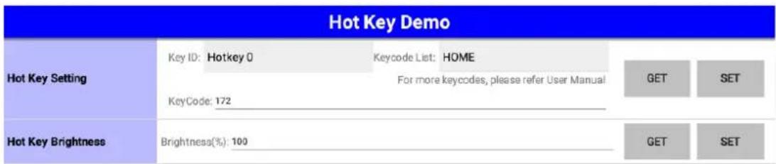
4.5.12 Hot Key
This page demonstrates the Hotkey APIs.
In the "Hoy Key Setting" row, you can set the keycode of corresponding function key on the device. The keycode list will show the common keycode for easy setting.
In the "Hoy Key Brightness" row, you can set the brightness of LED back light of the function keys.
4.6 VCIL Demonstration
The VCIL sample APP (VCILSample.apk) demonstrates the usage of VCIL APIs.
In the entry page, you should first set the protocol for each physical port properly in the "module settings" before you start other VCIL demo. Then, you can scroll to the bottom of the page and tap on the items in the VCIL demo function list to execute the demos. The following sections show the usage guide line of each items.
NOTE:
There might be some functions which are not supported on your device.
For the details of supported functions, please refer to the hardware spec.

| VCIL DEMO | ||
| VCIL MODULE SETTINGS | ||
| Firmware Version | 2.10 | |
| Module Reset | N/A | RESET |
| Module Settings | Get OK | |
| CAN PORT 0: CAN | GET | |
| CAN PORT 1: CAN | SET | |
| J1708 PORT 0: J1708 | ||
| VCIL DEMO | ||
| Module Settings | CAN PORT 0: CAN | GET |
| CAN PORT 1: CAN | SET | |
| J1708 PORT 0: J1708 | ||
| VCIL DEMO FUNCTION | ||
| CAN | J1939 | ODB2 |
| J1708 | J1587 | |
4.6.1 CAN
This page demonstrates the CAN APIs.
There are two scrolling areas in this page. The left side contains the demo of CAN port speed setting, CAN message sending, and CAN port error status getting. The right side contains the demo of CAN message receiving.
• CAN Port Speed Setting
In the "CAN PORT SPEED" area, you can set the bit rate for each CAN port.
Please note that you should also configure the bit rate for CAN port before you start J1939 and OBD2 demo page.
The CAN, J1939, OBD2 demo may not be operational.
• CAN Message Sending
In the "SEND" area, you can set the contents of a CAN message and press "SEND" button to send the message to CAN bus.
• CAN Port Error Status Getting
In the "CAN PORT ERROR STATUS" area, you can press "GET" button to get the error status of specific CAN port.
• CAN Message Receiving
In the "RECEIVE" area, all received CAN messages will be categorized and shown in the list view. The messages from the same CAN port with same CAN message ID will be updated to the same row in the list view and the "COUNT" column will increase.
You can press the "SET FILTER" button to enter the CAN Filter demo page.
NOTE:
- You must properly set the protocol in the entry page or the demo will not be operational.
- You must set the CAN port speed properly or the sending and receiving function in CAN, J1939, OBD2 demo page will not be operational.

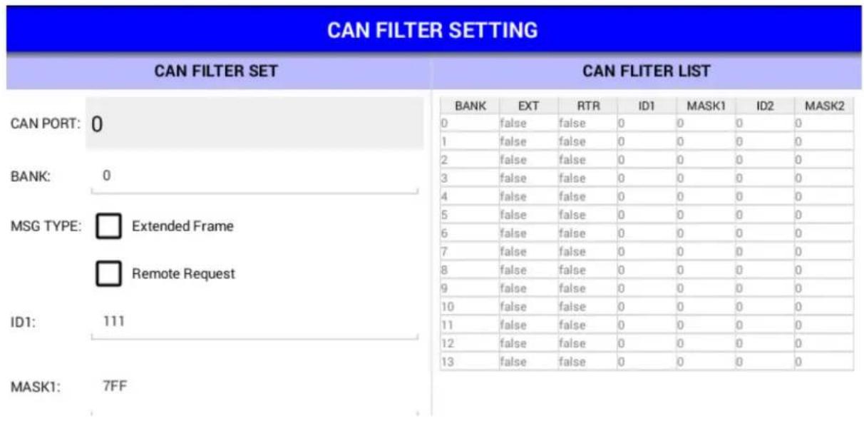
4.6.2 CAN Filter
This page demonstrates the CAN APIs related to CAN message filter.
There are two scrolling areas in this page. The left side contains the demo of CAN message filter settings. The right side shows the filter of specific CAN port.
In the left side you can specify a filter (CAN ID) of specific CAN port and press "SET" button to apply it or "REMOVE" to remove the filter. To show the filters applied on specific CAN port, you can choose the CAN port ID and press the "GET" button and all filters will be shown to the right side.
In the right side, you can tap on the row in the list view to load the filter settings to the columns in left side.
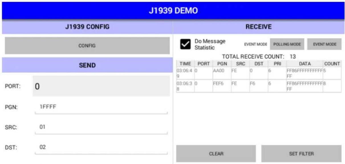
4.6.3 J1939
This page demonstrates the J1939 APIs.
There are two scrolling areas in this page. The left side contains the demo of J1939 config, and J1939 message sending. The right side contains the demo of J1939 message receiving.
- J1939 Config
Press the "CONFIG" button to enter the J1939 config page. You can configure the address and J1939 NAME in the page.
• J1939 Message Sending
In the "SEND" area, you can set the contents of a J1939 message and press "SEND" button to send the message to CAN bus.
• J1939 Message Receiving
In the "RECEIVE" area, all received J1939 messages will be categorized and shown in the list view. The messages from the same CAN port with same PGN will be updated to the same row in the list view and the "COUNT" column will increase.
You can press the "SET FILTER" button to enter the J1939 Filter demo page.
NOTE:
- You must properly set the protocol in the entry page or the demo will not be operational.
- You must set the CAN port speed properly or the sending and receiving function in CAN, J1939, OBD2 demo page will not be operational.
4.6.4 J1939 Config
This page demonstrates the J1939 APIs related to J1939 configuration.
You can set/get the address and J1939 NAME in this page. Please refer to SAE J1939-81 for the definitions of J1939 NAME.
| J1939 CONFIG | |
| PORT: | 0 |
| Address: | Ec |
| Arbitrary Addr. Capable: | 0 |
| Industry Group: | 1 |
| Vehicle System Instance: | 0 |
| Vehicle System: | 1 |
| Function: | FF |
4.6.5 J1939 Filter
This page demonstrates the J1939 APIs related to J1939 message filter.
There are two scrolling areas in this page. The left side contains the demo of J1939 message filter settings. The right side shows the filter of specific J1939 port.
In the left side you can specify a filter (PGN) of specific CAN port and press "SET" button to apply it or "REMOVE" to remove the filter. To show the filters applied on specific CAN port, you can choose the CAN port ID and press the "GET" button and all filters will be shown to the right side.
In the right side, you can tap on the row in the list view to load the filter settings to the columns in left side.
4.6.6 OBD2
This page demonstrates the OBD2 APIs.
There are two scrolling areas in this page. The left side contains the demo of CAN port speed setting, OBD2 message sending. The right side contains the demo of OBD2 message receiving.
• OBD2 Message Sending
In the "SEND" area, you can set the contents of a OBD2 message and press "SEND" button to send the message to CAN bus.
• OBD2 Message Receiving
In the "RECEIVE" area, all received OBD2 messages will be categorized and shown in the list view. The messages from the same CAN port with same message type, source address and destination address will be updated to the same row in the list view and the "COUNT" column will increase.
You can press the "SET FILTER" button to enter the OBD2 Filter demo page.
NOTE:
- You must properly set the protocol in the entry page or the demo will not be operational.
- You must set the CAN port speed properly or the sending and receiving function in CAN, J1939, OBD2 demo page will not be operational.
| OBD2 DEMO | ||||||||
| SEND | RECEIVE | |||||||
| PORT: | 0 | Do Message Statistic | EVENT MODE | POLLING MODE | EVENT MODE | |||
| Type: | VCIL_OBD2_TYPE_PHYSICAL | TOTAL RECEIVE COUNT: 9 | ||||||
| SRC: | 01 | TIME | PORT | TYPE | SRC | DST | PRI | DATA |
| 03:25:49 | 0 | DB | F1 | 11 | 6 | 0100 | ||
| 03:25:42 | 0 | DB | F1 | 33 | 6 | 0100 | ||
| 03:25:37 | 0 | DA | F1 | 33 | 6 | 0100 | ||
| DST: | 02 | |||||||
| PRIORITY: | 3 | |||||||
| DATA: | AABBCCDD112233 | CLEAR | SET FILTER | |||||
4.6.7 OBD2 Filter
This page demonstrates the OBD2 APIs related to OBD2 message filter.
There are two scrolling areas in this page. The left side contains the demo of OBD2 message filter settings. The right side shows the filter of specific CAN port.
In the left side you can specify a filter (PID, please refer to ISO 15031-5) of specific CAN port and press "SET" button to apply it or "REMOVE" to remove the filter. To show the filters applied on specific CAN port, you can choose the CAN port ID and press the "GET" button and all filters will be shown to the right side.
In the right side, you can tap on the row in the list view to load the filter settings to the columns in left side.

4.6.8 J1708
This page demonstrates the J1708 APIs.
There are two scrolling areas in this page. The left side contains the demo of J1708 message sending. The right side contains the demo of J1708 message receiving.
• J1708 Message Sending
In the "SEND" area, you can set the contents of a J1708 message and press "SEND" button to send the message to J1708 bus.
• J1708 Message Receiving
In the "RECEIVE" area, all received J1708 messages will be categorized and shown in the list view. The messages with same MID will be updated to the same row in the list view and the "COUNT" column will increase.
You can press the "SET FILTER" button to enter the J1708 Filter demo page.
NOTE:
- You must properly set the protocol in the entry page or the demo will not be operational.

4.6.9 J1708 Filter
This page demonstrates the J1708 APIs related to J1708 message filter.
There are two scrolling areas in this page. The left side contains the demo of J1708 message filter settings. The right side shows the filter of the J1708 port.
In the left side you can specify a filter (MID) and press "SET" button to apply it or "REMOVE" to remove the filter. To show the filters applied on J1708 port, you can press the "GET" button and all filters will be shown to the right side.
In the right side, you can tap on the row in the list view to load the filter settings to the columns in left side.

flowchart
graph TD
    A["J1708 FILTER"] --> B["MID: AA"]
    B --> C["ADD"]
    B --> D["REMOVE"]
    B --> E["GET ALL (show in ListView)"]
    F["J1708 FILTER RESET"] --> G["RESET"]
    H["J1708 FILTER LIST"] --> I["MID"]
    I --> J["01"]
    I --> K["AA"]
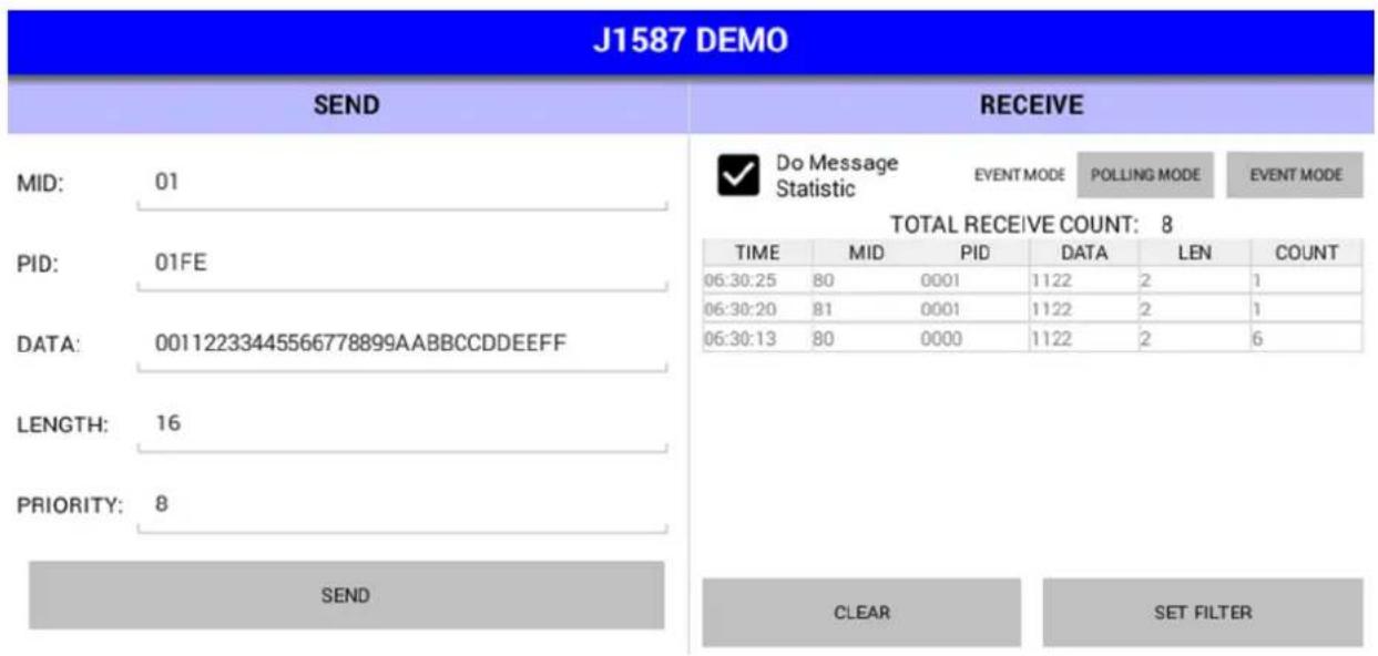
4.6.10 J1587
This page demonstrates the J1587 APIs.
There are two scrolling areas in this page. The left side contains the demo of J1587 message sending. The right side contains the demo of J1587 message receiving.
• J1587 Message Sending
In the "SEND" area, you can set the contents of a J1587 message and press "SEND" button to send the message to J1587 bus.
• J1587 Message Receiving
In the "RECEIVE" area, all received J1587 messages will be categorized and shown in the list view. The messages with same MID will be updated to the same row in the list view and the "COUNT" column will increase.
You can press the "SET FILTER" button to enter the J1708 Filter demo page.
NOTE:
- You must properly set the protocol in the entry page or the demo will not be operational.
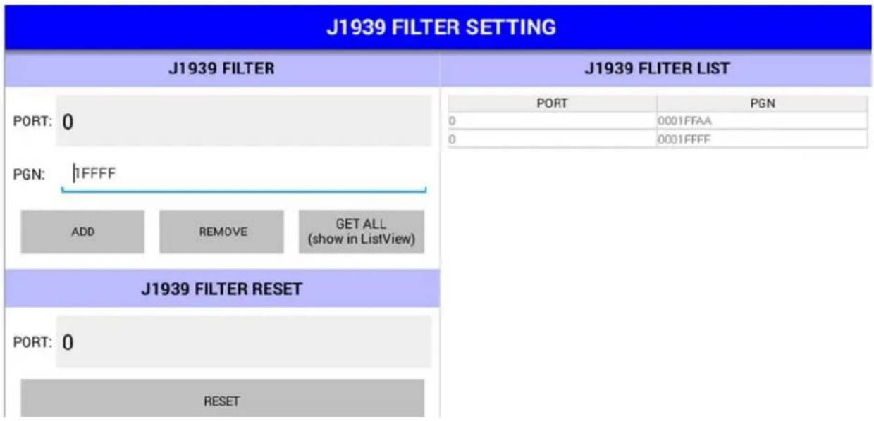
4.6.11 J1587 Filter
This page demonstrates the J1587 APIs related to J1587 message filter.
There are two scrolling areas in this page. The left side contains the demo of J1587 message filter settings. The right side shows the filter of the J1587 port.
In the left side you can specify a filter (PID) and press "SET" button to apply it or "REMOVE" to remove the filter. To show the filters applied on J1708 port, you can press the "GET" button and all filters will be shown to the right side.
In the right side, you can tap on the row in the list view to load the filter settings to the columns in left side.
J1587 FILTER SETTING
J1587 FILTER
J1587 FLITER LIST
PID: 000A
ADD
REMOVE
GETALL
(show in ListView)
PID
0001
000A
J1587 FILTER RESET
RESET
Appendix
A
This appendix explains the optional peripherals installation
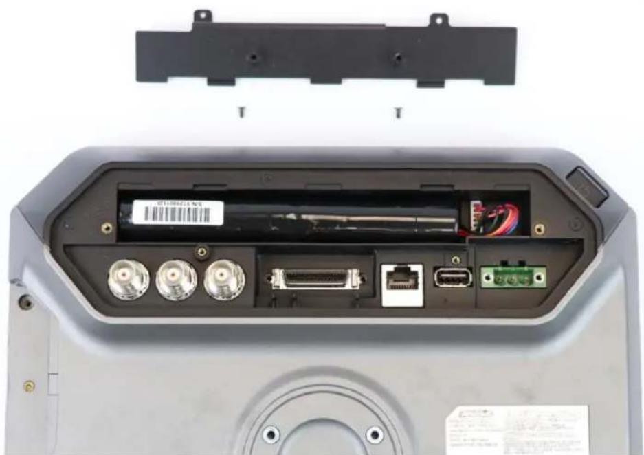
A-1 Installing Backup Baery
- Remove the screws on backup baery cover

natural_image
Close-up of a device rear panel showing ports, connectors, and a hand inserting a cable (no visible text or symbols)- Install the backup baery into the baery slot

natural_image
Interior view of a device showing external casing, ports, and battery pack (no text or symbols visible)
natural_image
Hand inserting cable into a device casing, showing ports and connectors (no text or symbols visible)Note: Please install the connector in correct direcon (the connector is anproof)

natural_image
Close-up of a hand inserting cables into an electronic device's internal components, highlighting a red circle to a component with a white connector (no text or symbols visible)
natural_image
Hand inserting a battery into an electronic device casing, showing ports and connectors (no text or symbols visible)- Locked the baery cover.
natural_image
Interior view of a device showing external components including ports, connectors, and a back panel (no visible text or symbols)
natural_image
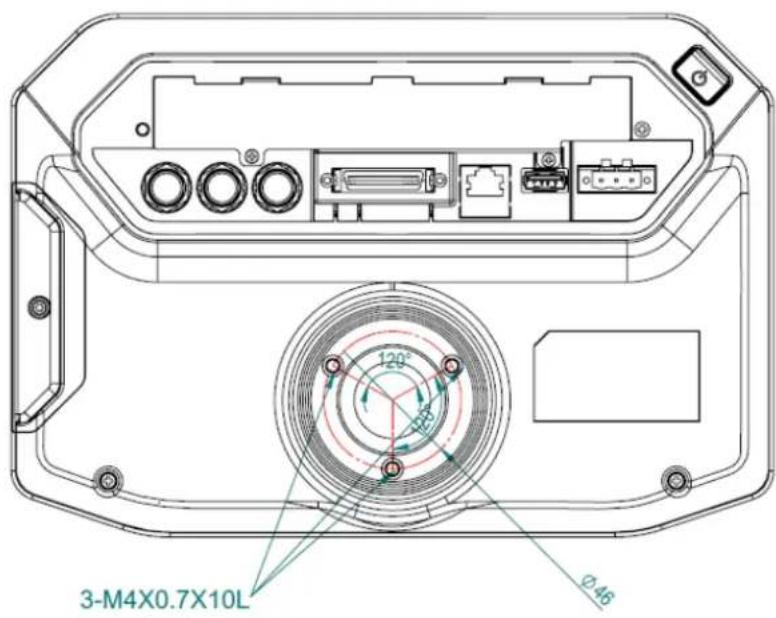
Hand inserting a USB into a device rear panel, showing ports and connectors (no text or symbols visible)A-2 Installing RAM mount kit
TREK-734 designed a RAM mount hole to support ram mount kit. Refer to below dimension. It needs to use 3pcs M4x0.7x10L screws.
TREK-734 using as portrait monitor only.
Note: When adjust angle of RMA mount need to loosen the screws on RMA mount to prevent the TREK-734 damage.
A-3 Installing IP54 I/O Cover
Part A –Water proong Rubber
Part B - Cover Top
Part C—Longer Screws (2 side)
Part D—Shorten Screws (middle)
Part E –Cover Boom

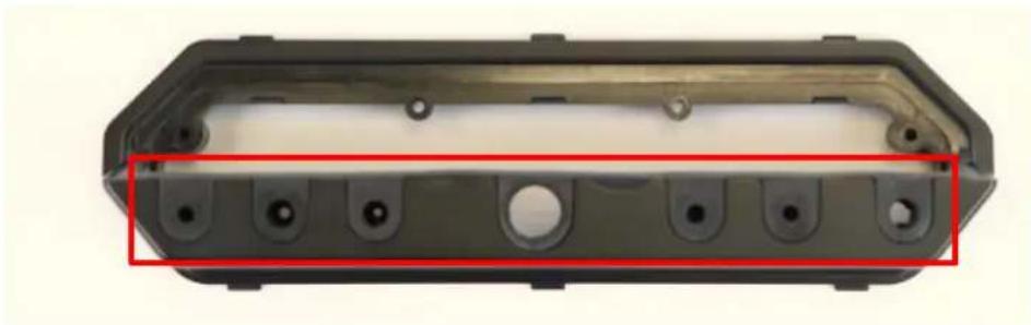
natural_image
Black rectangular electronic device with four metallic pins and three circular mounting holes, mounted on a white background (no text or symbols visible)
natural_image
Exterior view of a black plastic enclosure with mounting holes and three red-circled features (no text or symbols)- Insert the Part E- Cover Boom into the chassis clip.
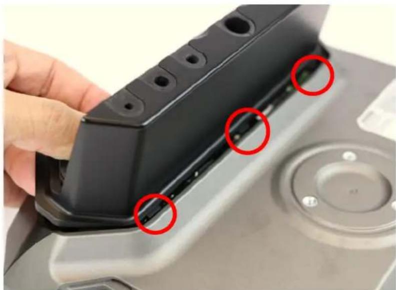
natural_image
Close-up of a hand holding a black plastic mechanical component with three red-circled features, no visible text or symbols.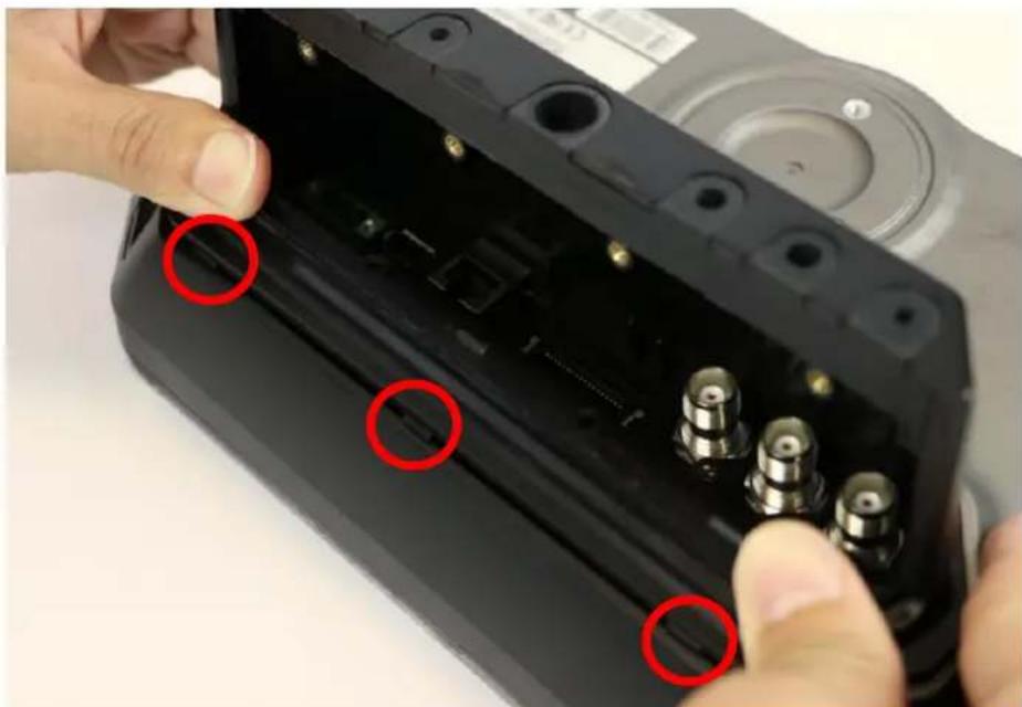
natural_image
Close-up of hands installing a black electronic device into a housing, with red circles highlighting the ports (no text or symbols visible)- Install the screws and ghtening screws. (2 dierent size screws, the part C – longer screw in 2 side, part D- the shorten screws in the middle)

natural_image
Close-up of a device's internal component with three red-circled ports and a screwdriver inserted (no visible text or symbols)- Install the Part B cover - Top and ghten the screws of cover top.

natural_image
Close-up of hands installing a black electronic device panel with multiple ports (no visible text or symbols)
natural_image
Close-up of a black electronic device with three screw holes and a red-handled tool inserted, no visible text or symbols.- Insert the Part A- Water Proong Rubber into the screw holes

natural_image
Close-up of hands holding a black electronic device with three circular buttons on its top (no text or symbols visible)A-4 Installing HDC cable
- Insert the HDC cable before install the IP54 cover and ghten the screws on HDC cable.
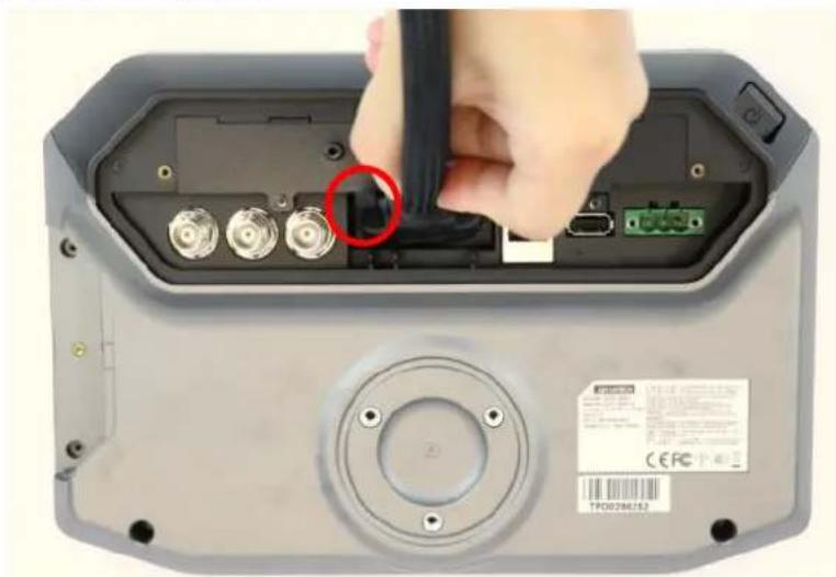
natural_image
Close-up of a device's internal components with a hand inserting a cable, showing ports and connectors (no readable text or symbols)- Fix the HDC into the rubber of IP54 I/O cover, please remove the rubber in Cover Boom.
natural_image
Exterior view of a black plastic enclosure with multiple circular holes and mounting holes, highlighted by a red rectangle (no text or symbols)
natural_image
Close-up of a black electronic device showing internal components including a coiled cable and three gold connectors (no text or symbols visible)- Install the Part B cover - Top and tighten the screws of cover top.

natural_image
Close-up of hands holding a black 3D device with four circular buttons and a cable, no visible text or symbols
natural_image
Close-up of a black electronic device with three screw holes and a red-handled tool inserted, no visible text or symbols.ADIANTECH
www.advantech.com
Please verify specifications before quoting. This guide is intended for reference purposes only.
All product specifications are subject to change without notice.
No part of this publication may be reproduced in any form or by any means, electronic, photocopying, recording or otherwise, without prior written permission of the publisher.
All brand and product names are trademarks or registered trademarks of their respective companies.
© Advantech Co., Ltd. 2010
- TREK-734
- RISC All-in-One Heavy duty Mobile Data Terminal
- Copyright
- Acknowledgements
- Product Warranty (2 years)
- Declaration of Conformity
- CE
- FCC Class B
- FCC Caution:
- FCC RF Radiation Exposure Statement :
- Technical Support and Assistance
- Warnings, Cautions and Notes
- Document Feedback
- Packing List
- Ordering Information
- Optional Accessories
- Safety Instructions
- Safety Precaution - Static Electricity
- Warning!
- Contents
- Chapter 1 General Information ....1
- Chapter 2 System Setup ....7
- Chapter 3 I/O connectors Pin assignments.....28
- Chapter 4 Software Demo Utility Setup....34
- VCIL Demonstration....57
- Appendix A Peripheral Installaon....70
- Chapter 1
- General Information
- Introduction
- General Specifications
- Features
- Dimensions
- Chapter 2
- System Setup
- A Quick Tour of the TREK-734 Computer
- Installation Procedures
- Installing SIM car & Storage card
- Connecting Power
- Power Connector
- Chapter 3
- I/O Connectors
- I/O Connectors Pin Assignment
- Power connector
- Power in Jack Cable
- PIN Signal Depiction
- High Density Connector
- High density cable
- USB Connector
- Chapter 4
- Software Demo Utility Setup
- MRM SDK Package Contents & Overview
- IVCP Service Client API Modules:
- • SDP (Smart Display Panel)
- SDP Service Client API Modules:
- • VCIL (Vehicle Communication Interface Layer)
- VCIL API Modules:
- How MRM SDK Works
- Installation of the MRM SDK
- Unzip the SDK package
- Install MRM Services (mrm\_service.apk)
- ○ RUNNING
- ○ NOT\_INITIALIZED
- - UNKNOWN
- - STOP
- Import MRM Service Client APIs Library
- - Click the "Dependency" tab. Then click "+" -> "File dependency"
- - Select the lib file.
- Import VCIL APIs Library
- - Repeat the above steps to add all libs and you will see all libs are added to the list.
- Install Prebuilt Sample Apps
- IVCP Demonstration
- Information
- Firmware
- Power Management
- NOTE:
- Battery
- Alarm
- Watchdog
- Digital IO
- Peripheral Control
- Storage
- G Sensor
- G Sensor Alarm
- P Sensor
- Hot Key
- VCIL Demonstration
- CAN
- • CAN Port Speed Setting
- • CAN Message Sending
- • CAN Port Error Status Getting
- • CAN Message Receiving
- CAN Filter
- J1939
- - J1939 Config
- • J1939 Message Sending
- • J1939 Message Receiving
- J1939 Config
- J1939 Filter
- OBD2
- • OBD2 Message Sending
- • OBD2 Message Receiving
- OBD2 Filter
- J1708
- • J1708 Message Sending
- • J1708 Message Receiving
- J1708 Filter
- J1587
- • J1587 Message Sending
- • J1587 Message Receiving
- J1587 Filter
- J1587 FILTER SETTING
- J1587 FILTER
- J1587 FLITER LIST
- J1587 FILTER RESET
- Appendix
- A
- A-1 Installing Backup Baery
- A-2 Installing RAM mount kit
- A-3 Installing IP54 I/O Cover
- A-4 Installing HDC cable
- ADIANTECH
- www.advantech.com
Brand : Advantech
Model : TREK-734
Category : Scale