P50XHA10W - Suivi FUJITSU - Free user manual and instructions
Find the device manual for free P50XHA10W FUJITSU in PDF.

User questions about P50XHA10W FUJITSU
0 question about this device. Answer the ones you know or ask your own.
Ask a new question about this device
Download the instructions for your Suivi in PDF format for free! Find your manual P50XHA10W - FUJITSU and take your electronic device back in hand. On this page are published all the documents necessary for the use of your device. P50XHA10W by FUJITSU.
USER MANUAL P50XHA10W FUJITSU
42"/50" WIDE PLASMA DISPLAY
P42VHA10W/P42VHA10A/
P42HHA10W/P42HHA10A/
P50XHA10W/P50XHA10A/P50XHA10U/
natural_image
Illustration of a flat-screen monitor with a black border and 'Rispro' logo on the front panel (no text or symbols on screen)Contents
Page Page
Before Use
• Safety Precautions E-2–E-3
- Features ......E-4
- Accessories E-5
- Handy Tips ...... E-5
- Installation E-6
Usage
• Part Names and Functions …… E-7–E-10
• Using the Remote Control …… E-11–E-12
- Connecting the Display to External Equipment
E-13-E-17
• Basic Operations ...... E-18–E-19
- Selecting Input Mode ......E-20
- Other Basic Operations ...... E-21
- Watching Pictures on the Wide Screen
E-22-E-23
Adjustments
- Adjustment Menu ...... E-24
- Adjusting Pictures (PICTURE Menu) ... E-25–E-27
- Adjusting Screen Position and Size (POSITION/SIZE Menu) …… E-28–E-29
- Adjusting AUDIO (AUDIO Menu) …… E-30–E-31
- Other Adjustments (FEATURES Menu) E-32-E-38
- Initialization of User Adjustment Value (FACTORY DEFAULT) ......E-39
Others
- Options ......E-40
- Factory Settings ...... E-41
- Specification E-42-E-44
- Cleaning and Maintenance ....E-45
Before using the display, read this manual carefully so that you know how to use the display correctly.
Refer to this manual whenever questions or problems about operation arise. Be sure to read and observe the safety precautions.
Keep this manual where the user can see it easily.
* Installation and removal require special expertise. Consult your product dealer for details.
IMPORTANT INFORMATION
IMPORTANT

The lightning flash with arrowhead symbol, within an equilateral triangle, is intended to alert the user to the presence of uninsulated “dangerous voltage” within the product’s enclosure that may be of sufficient magnitude to constitute a risk of electric shock to persons.

CAUTION: TO PREVENT THE RISK OF ELECTRIC SHOCK, DO NOT REMOVE COVER (OR BACK). NO USER-SERVICEABLE PARTS INSIDE. REFER SERVICING TO QUALIFIED SERVICE PERSONNEL.

The exclamation point within an equilateral triangle is intended to alert the user to the presence of important operating and maintenance (servicing) instructions in the literature accompanying the appliance.
WARNING: This is a Class A and Class B product. In a domestic environment this product may cause radio interference in which case the user may be required to take adequate measures.
WARNING: TO REDUCE THE RISK OF FIRE AND ELECTRIC SHOCK, DO NOT EXPOSE THIS PRODUCT TO RAIN OR MOISTURE.
FCC NOTICE
• P42VHA10W/P50XHA10W: A Class A digital device
This equipment has been tested and found to comply with the limits for a Class A digital device, pursuant to Part 15 of the FCC Rules. These limits are designed to provide reasonable protection against harmful interference when the equipment is operated in a commercial environment. This equipment generates, uses, and can radiate radio frequency energy and, if not installed and used in accordance with the instruction manual, may cause harmful interference to radio communications. Operation of this equipment in a residential area is likely to cause harmful interference in which case the user will be required to correct the interference at his own expense.
- P42VHA10A/P42HHA10W/P42HHA10A/P50XHA10A/P50XHA10U/P42VHA20W/P42VHA20A/P42VHA20U: A Class B digital device This equipment has been tested and found to comply with the limits for a Class B digital device, pursuant to Part 15 of the FCC Rules. These limits are designed to provide reasonable protection against harmful interference in a residential installation. This equipment generates, uses and can radiate radio frequency energy and, if not installed and used in accordance with the instructions, may cause harmful interference to radio communications. However, there is no guarantee that interference will not occur in a particular installation. If this equipment does cause harmful interference to radio or television reception, which can be determined by turning the equipment off and on, the user is encouraged to try to correct the interference by one or more of the following measures:
– Reorient or relocate the receiving antenna.
– Increase the separation between the equipment and receiver.
- Connect the equipment into an outlet on a circuit different from that to which the receiver is connected.
- Consult the dealer or an experienced radio/TV technician for help.
IMPORTANT SAFETY INSTRUCTIONS
Electrical energy can perform many useful functions. This unit has been engineered and manufactured to assure your personal safety. But IMPROPER USE CAN RESULT IN POTENTIAL ELECTRICAL SHOCK OR FIRE HAZARD. In order not to defeat the safeguards incorporated into this product, observe the following basic rules for its installation, use and service. Please read these “Important Safeguards” carefully before use.
1) Read these instructions.
2) Keep these instructions.
3) Heed all warnings.
4) Follow all instructions.
5) Do not use this apparatus near water.
6) Clean only with dry cloth.
7) Do not block any ventilation openings. Install in accordance with the manufacturer's instructions.
8) Do not install near any heat sources such as radiators, heat registers, stoves, or other apparatus (including amplifier's) that produce heat.
9) Do not defeat the safety purpose of the polarized or grounding-type plug. A polarized plug has two blades with one wider than the other. A grounding type plug has two blades and a third grounding prong. The wide blade or the third prong are provided for your safety. If the provided plug does not fit into your outlet, consult an electrician for replacement of the obsolete outlet.
10) Protect the power cord from being walked on or pinched particularly at plugs, convenience receptacles, and the point where they exit from the apparatus.
11) Only use attachments/accessories specified by the manufacturer.
12) Use only with the cart, stand, tripod, bracket, or table specified by the manufacturer, or sold with the apparatus.
When a cart is used, use caution when moving the cart/apparatus combination to avoid injury from tip-over.
13) Unplug this apparatus during lightning storms or when unused for long periods of time.
14) Refer all servicing to qualified service personnel. Servicing is required when the apparatus has been damaged in any way, such as power-supply cord or plug is damaged, liquid has been spilled or objects have fallen into the apparatus, the apparatus has been exposed to rain or moisture, dose not operate normally, or has been dropped.
- Unplug this product from the wall outlet before cleaning. Do not use liquid cleaners or aerosol cleaners. Use a damp cloth for cleaning.
- Do not use attachments not recommended by the product manufacturer as they may cause hazards.
- Do not use immediately after moving from a low temperature to high temperature, as this causes condensation, which may result in fire, electric shock, or other hazards.
– The apparatus shall not be exposed to dripping or splashing.
- No objects filled with liquids, such as vases, shall be placed on the apparatus.
- Do not place this product on an unstable cart, stand, or table. The product may fall, causing serious injury to a child or adult, and serious damage to the product. The product should be mounted according to the manufacturer's instructions, and should use a mount recommended by the manufacturer.
- When the product is used on a cart, care should be taken to avoid quick stops, excessive force, and uneven surfaces which may cause the product and cart to overturn, damaging equipment or causing possible injury to the operator.
- Slots and openings in the cabinet are provided for ventilation. These ensure reliable operation of the product and protect it from overheating. These openings must not be blocked or covered. (The openings should never be blocked by placing the product on bed, sofa, rug, or other similar surface. It should not be placed in a built-in installation such as a bookcase or rack unless proper ventilation is provided and the manufacturer's instructions have been adhered to.)
For proper ventilation, separate the product from other equipment, which may prevent ventilation, and keep distance more than 10 cm.
- This product should be operated only from the type of power source indicated on the label. If you are not sure of the type of power supply of your home, consult your product dealer or local power company.
- This product is equipped with a three-wire plug. This plug will fit only into a grounded power outlet. If you are unable to insert the plug into the outlet, contact your electrician to install the proper outlet. Do not defeat the safety purpose of the grounded plug.
- Power-supply cords should be routed so that they are not likely to be walked on or pinched by items placed upon or against them. Pay particular attention to cords at doors, plugs, receptacles, and the point where they exit from the product.
- For added protection for this product during a lightning storm, or when it is left unattended and unused for long periods of time, unplug it from the wall outlet and disconnect the cable system. This will prevent damage to the product due to lightning and power line surges.
- Do not overload wall outlets, extension cords, or convenience receptacles on other equipment as this can result in a risk of fire or electric shock.
- Never push objects of any kind into this product through openings as they may touch dangerous voltage points or short out parts that could result in a fire or electric shock. Never spill liquid of any kind on the product.
- Do not attempt to service this product yourself as opening or removing covers may expose you to dangerous voltages and other hazards. Refer all service to qualified service personnel.
- Unplug this product from the wall outlet and refer service to qualified service personnel if the product does not operate normally by following the operating instructions. Adjust only those controls that are covered by the Operation Manual, as an improper adjustment of other controls may result in damage and will often require extensive work by a qualified technician to restore the product to its normal operation.
- When replacement parts are required, be sure the service technician has used replacement parts specified by the manufacturer or with same characteristics as the original part. Unauthorized substitutions may result in fire, electric shock, or other hazards.
- Upon completion of any service or repairs to this product, ask the service technician to perform safety checks to determine that the product is in proper operating condition.
- The product should be placed more than one foot away from heat sources such as radiators, heat registers, stoves, and other products (including amplifiers) that produce heat.
- When connecting other products such as VCR's, and personal computers, you should turn off the power of this product for protection against electric shock.
- Do not place combustibles behind the cooling fan. For example, cloth, paper, matches, aerosol cans or gas lighters that present special hazards when overheated.
- Use only the accessory cord designed for this product to prevent shock.
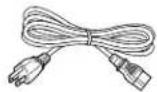
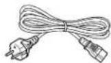
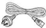
The power supply voltage rating of this product is AC110–240 V (42"10W/A) and AC220–240 V (50"W/A, 42"20W/A type) and AC 120 V (U type), and the power cord attached conforms to the following power supply voltage. Use only the power cord designated by our dealer to ensure Safety and EMC.
When it is used with other power supply voltage, the power cable must be changed.
Use the standard power plug and cord set of the specified country.
Consult your product dealer.
Power supply voltage:
AC 100–125 V
(42"10W, 42"U, 50"U Type: Included)
Power cord
AC 200-240 V (42"20W, 50"W Type: Included)

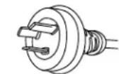
AC 240 V (SAA TYPE)
(42"A, 50"A Type: Included)
Variety of input signals
- The unit features four video and four S-video input terminals, and five component video terminals.
- In addition to mD-sub terminal, the display also supports input of digital RGB signal input enabling DVI standard (HDCP*) high definition picture quality.
- Depending on the model, the display supports video input for different color television systems as follows: NTSC, PAL, SECAM, PAL60, N-PAL, M-PAL, 4.43NTSC.
Desired screen size
- This display offers a total of five different screen sizes in video input mode: Normal, Wide1, Wide2, Zoom1, and Zoom2.
A Normal mode is also available for displaying of normal-size (4:3 aspect ratio) pictures. - The display has a Compose mode to switch screen size automatically depending on the contents of software.
- Three different screen sizes in RGB input mode (Normal, Wide, and Zoom) are also available.
Picture quality
- Pro-setting allows adjustment for even higher picture quality.
- Noise reduction function reduces noise to ensure clear pictures.
- A display suitable for such film materials as movie pictures can be made by 24 frame mode function.
Convenient power saving setting
- When no video signal is input to the display or the remote control is not operated for a long time, this function automatically reduces the power consumption of the unit.
Others
- The white screen and screen orbiter functions are available to minimize phosphor burn-in.
- 3 audio input terminals and 20W + 20W(42^ ) / 12W + 12W(50^ ) external speaker output terminal are available.
CHECKING ACCESSORIES
One remote control Two AA batteries

One user's manual One power cable Two big ferrite

(42"10W, 42"20U, 50"U Type)
(42"20W, 50"W Type)
(42"A, 50"A Type)
Two small ferrite
cores
cores


HANDY TIPS
- Viewing the screen constantly for extended periods can strain your eyes. Be sure to stay at a proper distance (at least 1.5 m or 5 feet (42")/1.9 m or 6.3 feet (50")) from the screen and to look occasionally away while working.
- Have the display inspected and cleaned by your dealer at regular intervals.
- Pictures may become "burnt" into the screen phosphors if the screen is left on for extended periods. To ensure that the display has a prolonged service life, be sure to use a screen orbiter, white screen. This will ensure the same picture or pattern is not constantly displayed for long periods. (See P. E-37–E-38.)
- The plasma display panel, which is built for maximum precision, provides more than 99.99% effective pixels. You may find, however, that some pixels constantly remain lit or dimmed.
- The display has a fan to prevent its internal temperature from rising.
- Be careful with the air delivered by the fan. It may be very hot.
- Contact your dealer if you find that the display does not seem to function properly when used with other audio-visual equipment.
You may need to move your display if it produces degraded pictures or noise due to electromagnetic radiation, or if the infrared remote control does not function properly. - Pictures may not be displayed properly if you connect a non-standard PC to the RGB input terminal. In this case, contact your dealer for more information.
- The protective circuit, built into the display, automatically turns off the power if the display has a problem. In this case, you will see that the power indicator lamp flashes red.
Warning
If the power indicator lamp flashes red, this signifies that the display has developed a problem. When this happens, be sure to remove the power plug from the receptacle to prevent fire or electric shock. Then, check the display in accordance with the instructions given on P. E-45, or contact your dealer.
Information
Cables for connecting the display to external equipment are not supplied. Contact your dealer for more information on these products.
To prevent the display's internal components from overheating, make sure that the display is installed in a well-ventilated location. Be sure to use the optional stand, wall-mounting unit or the other unit when installing the display. Also, be also sure that your dealer performs the installation.
See the appropriate instruction manual for more information on the installation hardware you select.
To prevent an accident and ensure safety in the event of an earthquake, fix the display securely into position as described below.
To ensure proper heat radiation, provide at least as much space around the display as shown below.
* Make sure that the display is installed in a location where the temperature can be maintained between 0°C and 40°C.
* Never attempt to tilt the display sideways or backward.
* To prevent the power and other cables from being accidentally pulled, make sure that they run along the wall or through corners.
* The display can be installed with either of its sides facing down.
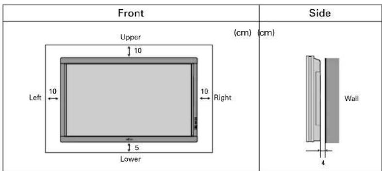
text_image
Front Upper (cm) (cm) Left 10 10 Right Lower Wall 4Note
The display is a highly precise piece of equipment and therefore must be packed properly before transportation. Be sure to use only those packing materials originally supplied with the display when repacking it.
Reference
See P. E-40 for more information on options.
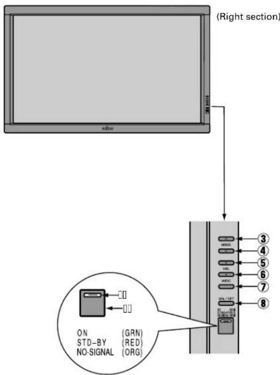
DISPLAY SECTION - FRONT
text_image
(Right section) ON STD-BY (GRN) NO-SIGNAL (RED) NO-SIGNAL (ORG)Control Panel (Right side of display)
①Power indicator lamp
This lamp shows the state of the power supply.
Lit (red): Stand-by
Lit (green): Power ON
Lit (orange): Power saving (DPMS: Power saving function) mode ON (See P. E-36.)
Flashing (red): Malfunction (Flashes differently depending on the type of malfunction. See P. E-45 for more information.)
②Remote control signal receiver
Receives signals from the remote control.
③Input mode selector button ▲ [MODE]
④Input mode selector button ▼ [MODE]
Switches between picture input modes.
⑤VOL + button
⑥VOL - button
Adjusts the sound volume.
⑦Wide screen selector button [WIDE]
Switches the screen over to a desired wide screen.
⑧ON/OFF button
Turns the power "ON" and "OFF (standby state)".
Warning
If the power indicator lamp flashes red, this signifies that the display has developed a problem. When this happens, be sure to remove the power plug from the receptacle and contact your dealer. Leaving the display power ON can result in fire or electric shock.
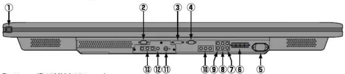
DISPLAY SECTION – LOWER PART
Bottom (P42VHA10 type)
text_image
① ② ③ ④ ⑬ ⑭ ⑮ ⑯ ⑰ ⑱ ⑲ ⑳ ⑴ ⑵ Bottom (R12001-16) Bottom (R12001-16)Bottom (P42HHA10 type)
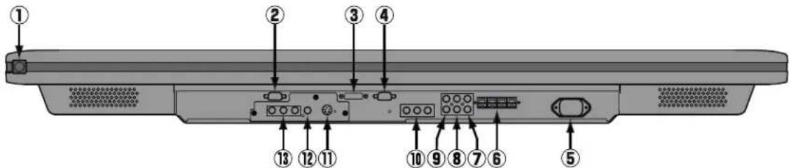
text_image
Diagram of a device rear panel with numbered labels pointing to ports and connectorsBottom (50")
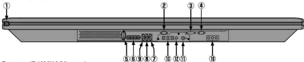
text_image
① ② ③ ④ ⑤ ⑥ ⑦ ⑧ ⑨ ⑩ Bottom (P40V/1A30 type)Bottom (P42VHA20 type)
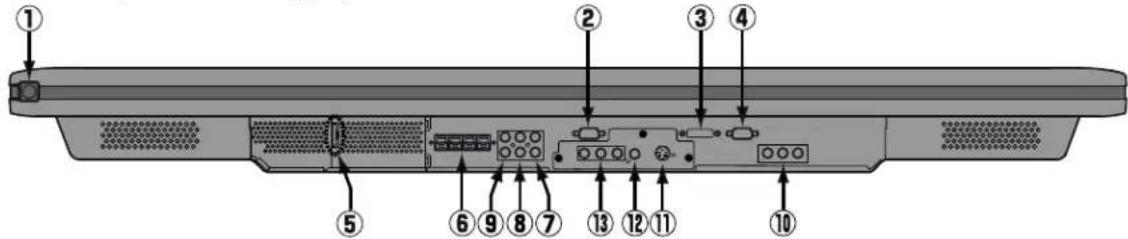
text_image
Labeled diagram of a computer monitor rear panel showing numbered components for identification①/10 power switch
When pressed while in the "OFF" state, the power indicator lamp lights and the display is placed in the "ON ⏻" state, and the power can be turned "ON" or "OFF" by the remote control or on the control panel of the display. When pressed while in the "ON ⏻" state, the power indicator lamp goes out and the display is placed in the "OFF" state where power is still partly supplied.
②RS-232C terminal (RS-232C)
This terminal is provided for you to control the display from the PC. Connect it to the RS-232C terminal on the PC. When connecting a cable, attach a ferrite core to the cable. (See P. E-13.)
③RGB1 input terminal (RGB1 INPUT/DVI-D)
Connect this terminal to the PC's display (digital RGB) output terminal. *The connection cable No.88741-8000 made by molex Inc. is recommended.
④RGB2 input terminal (RGB2 INPUT/mD-sub)
Connect this terminal to the PC's display (analog RGB) output terminal or decoder (digital broadcast tuner, etc.) output terminal.
⑤Power input terminal
Connect this terminal to the power cable supplied with the display. When connecting a cable, attach a ferrite core to the cable. (See P. E-13.)
⑥External speaker output terminal (EXT SP)
Connect this terminal to the optionally available speaker.
When connecting a cable, attach a ferrite core to the cable. (See P. E-13.)
*See the speaker instruction manual for more information.
⑦Audio1 input terminal (AUDIO1 INPUT)
⑧Audio2 input terminal (AUDIO2 INPUT)
⑨Audio3 input terminal (AUDIO3 INPUT)
Connect this terminal to the sound output terminal of your VCR, etc. (See P.E-36 for the selection of audio input for video input.)
⑩ Component video input terminal (VIDEO3 INPUT)
Connect this terminal to the component video output (color difference output) terminal of your HDTV unit or DVD player.
⑪S-Video input terminal (VIDEO2 INPUT)
Connect this terminal to the S-video output terminal of your VCR.
⑫Video input terminal (VIDEO1 INPUT)
Connect this terminal to the video output terminal of your VCR.
⑬Component video input terminal (VIDEO4 INPUT)
Connect this terminal to the component video output (color difference output) terminal of your HDTV unit or DVD player.
Description of Input Terminals
DVI-D terminal (RGB1 INPUT/DVI-D)
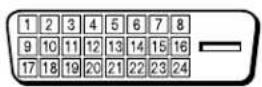
| Pin No. | Signal | Pin No. | Signal | Pin No. | Signal |
| 1 | T.M.D.S. Data2— | 9 | T.M.D.S. Data1— | 17 | T.M.D.S. Data0— |
| 2 | T.M.D.S. Data2+ | 10 | T.M.D.S. Data1+ | 18 | T.M.D.S. Data0+ |
| 3 | T.M.D.S. Data2 Shield | 11 | T.M.D.S. Data1 Shield | 19 | T.M.D.S. Data0 Shield |
| 4 | — | 12 | — | 20 | — |
| 5 | — | 13 | — | 21 | — |
| 6 | DDC Clock | 14 | +5V Power | 22 | T.M.D.S. Clock Shield |
| 7 | DDC Data | 15 | Ground(for +5V) | 23 | T.M.D.S. Clock+ |
| 8 | — | 16 | Hot Plug Detect | 24 | T.M.D.S. Clock— |
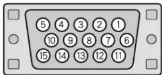
RGB2 input terminal (RGB2 INPUT/mD-sub)
text_image
⑤ ④ ③ ② ① ⑩ ⑨ ⑧ ⑦ ⑥ ⑮ ⑭ ⑬ ⑭ ⑮| Pin No. | Input signal Pin No. | Input signal | |
| 1 Red 9 — | |||
| 2 Green | 10 Ground | ||
| 3 Blue 11 — | |||
| 4 | — | 1 | 2 — |
| 5 Ground | 13 Horizontal synchronization | ||
| 6 Ground | 14 Vertical synchronization | ||
| 7 Ground | 15 — | ||
| 8 Ground | Frame Ground | ||
RS-232C terminal (RS-232C)
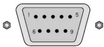
text_image
1 5 6 9| Pin No. | Signal |
| 1 | DCD (Data Carrier Detect) |
| 2 | RD (Received Data) |
| 3 | TD (Transmit Data) |
| 4 | DTR (Data Terminal ready) |
| 5 | GND (Ground) |
| 6 | DSR (Data Set Ready) |
| 7 | RTS (Request To send) |
| 8 | CTS (Clear To Send) |
| 9 | RI (Ring Indication) |
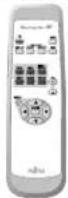
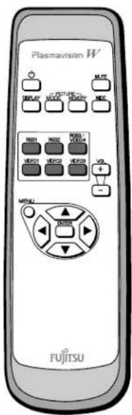
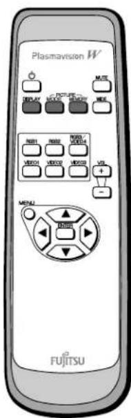
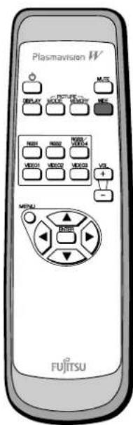
REMOTE CONTROL
For details, see page
① button

Switches between power ON and standby state.
③DISPLAY OFF button

For showing on-screen-information.
④PICTURE MODE button

Switches the picture mode.
⑦RGB input mode selector button [RGB 1-2] E-20
Selects RGB 1-2.
⑨Video input mode selector button [VIDEO 1-3] E-20
Selects VIDEO 1 - 3.
⑪Menu button [MENU]
Use this button to display a desired menu for adjusting the picture.
⑫Enter button [ENTER]
Press this button to finalize the selection of a desired menu or option within a menu.
text_image
Plasmavision W ① ② ③ ④ DISPLAY C-PICTURE MODE MEMORY MUTE ⑤ ⑥ RGB1 RGB2 RGB3/ VIDEO4 ⑦ VIDEO1 VIDEO2 VIDEO3 VOL + - ⑧ ⑨ ⑩ MENU ENTER ⑪ ⑫ FJITSU of②MUTE button

Temporarily mutes the sound.
⑤PICTURE MEMORY button

Recalls the PICTURE MEMORY.
⑥WIDE button

Switches the screen over to a desired wide screen.
⑧RGB3/VIDEO4 input mode selector button [RGB3/VIDEO4] E-20
Selects VIDEO4.
⑩Volume adjustment buttons
[VOL +/-] E-19
Adjust the volume.
Press the + button to increase the volume.
Press the - button to reduce the volume.
⑬Adjustment buttons [


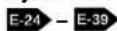
Use these buttons to scroll through options in a menu.
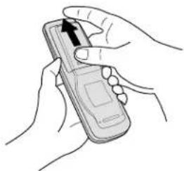
PUTTING BATTERIES IN THE REMOTE CONTROL
natural_image
Illustration of hands holding a mobile phone with an upward arrow (no text or symbols)①To remove the cover, slide it outwards while pressing it down.
natural_image
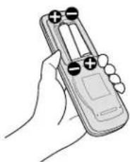
Line drawing of a hand holding a remote control device (no text or symbols visible)②Place two AA batteries in the remote control. Make sure that the batteries are properly oriented.
natural_image
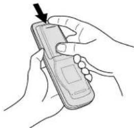
Line drawing of hands holding a mobile phone with an arrow pointing to the screen (no text or symbols present)③Close the cover until it snaps into place.
PRECAUTIONS
To prevent malfunction, be sure not to apply any form of severe shock to the remote control.
To prevent malfunction or deformation, be sure not to allow the remote control to become wet; also, keep it away from hot locations or heating equipment.
Be sure not to clean the remote control using a cloth dampened in any volatile solvent, such as benzene or thinner.
CAUTION: Be sure to use replacement batteries of the same type as the original ones. When disposing of used batteries, please comply with governmental regulations or environmental public institution's rules that apply in your country/area.
Note
The remote control will not function properly if the batteries are dead. Be sure to replace them as needed.
Do not use rechargeable batteries (Ni-Cd).
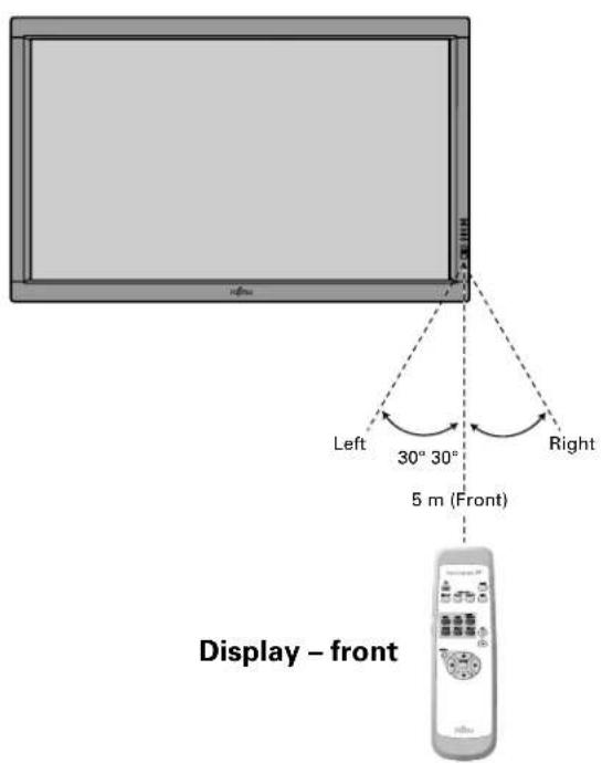
EFFECTIVE RANGE FOR THE REMOTE CONTROL
Point the remote control at the display's signal receiver when using it.
Make sure that there are no obstacles between the remote control and the display's signal receiver.
text_image
Left 30° 30° 5 m (Front) Right Display – front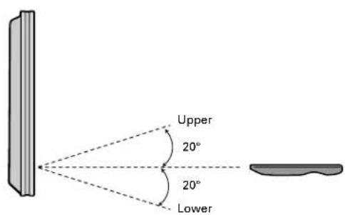
text_image
Upper 20° 20° LowerDisplay - side
Information
The remote control may not function properly if you use a high-frequency fluorescent lamp. If you experience problems, move the lamp or use the remote control from a different position.
CONNECTING THE DISPLAY TO EXTERNAL EQUIPMENT
Be sure to turn OFF the power to the display and external equipment before making any connections.
No cables are supplied with the display for connection to external equipment. The type of cable to be used varies depending on the PC model. Contact your dealer for more information.
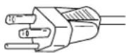
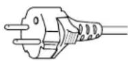
RECEPTACLE
Make sure that the power cable's grounding wire is grounded.
The display comes with a 3-prong power plug; one prong is connected to the grounding wire. If you have only a 2-hole receptacle, you will need to have it replaced. Contact your dealer for more information.
CONNECTING THE DISPLAY TO EXTERNAL EQUIPMENT
Carefully check the terminals for position and type before making any connections.
Loose connectors can result in picture or color problems. Make sure that all connectors are securely inserted into their terminals.
Ferrite cores
These ferrite cores are used to attenuate undesired signals.
Two big ferrite cores
When connecting a cable to the power input terminal, RS-232C terminal, attach one of these ferrite cores to the cable near the terminal.

text_image
Power Cable Ferrite Core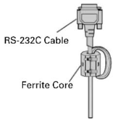
text_image
RS-232C Cable Ferrite CoreTwo small ferrite cores
When connecting a cable to the external speaker output terminal attach one of these ferrite cores to the cable near the terminal.


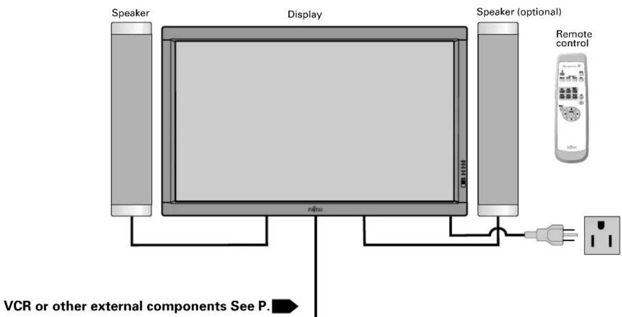
EXAMPLE OF CONNECTION TO EXTERNAL COMPONENTS
text_image
Speaker Display Speaker (optional) Remote control VCR or other external components See P.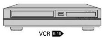
natural_image
Illustration of a VCR E-15 audio workstation (no text or symbols on the device body)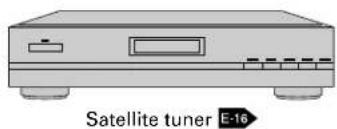
text_image
Satellite tuner E-16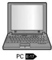
text_image
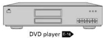
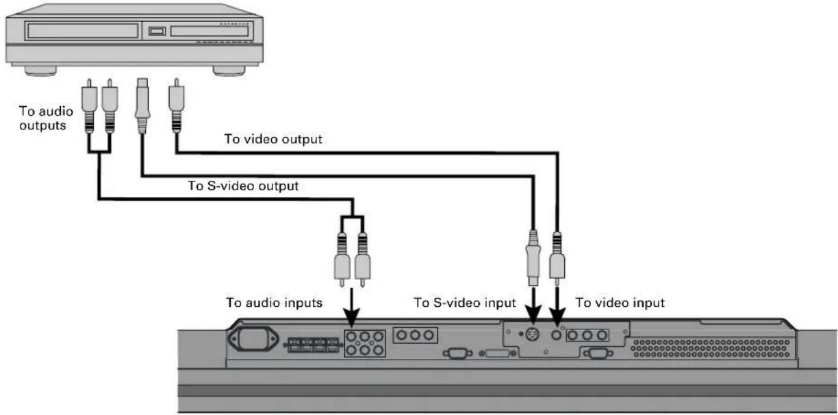
DVD player E-16VCR
- Connect the video signal cable to either the S-video input terminal or the video input terminal.
flowchart
graph TD
    A["Device"] -->|To audio outputs| B["Resistors"]
    A -->|To video output| C["Resistors"]
    A -->|To S-video output| D["Resistors"]
    A -->|To audio inputs| E["Resistors"]
    A -->|To S-video input| F["Resistors"]
    A -->|To video input| G["Resistors"]
Bottom of Display (Ex.: P42VHA10)
Note
- Unplug the power cord from the AC outlet before you connect external components.
- Also refer to the instructions for the component to be connected.
- When inputting audio, connect to the terminals corresponding to the used video input or RGB input.
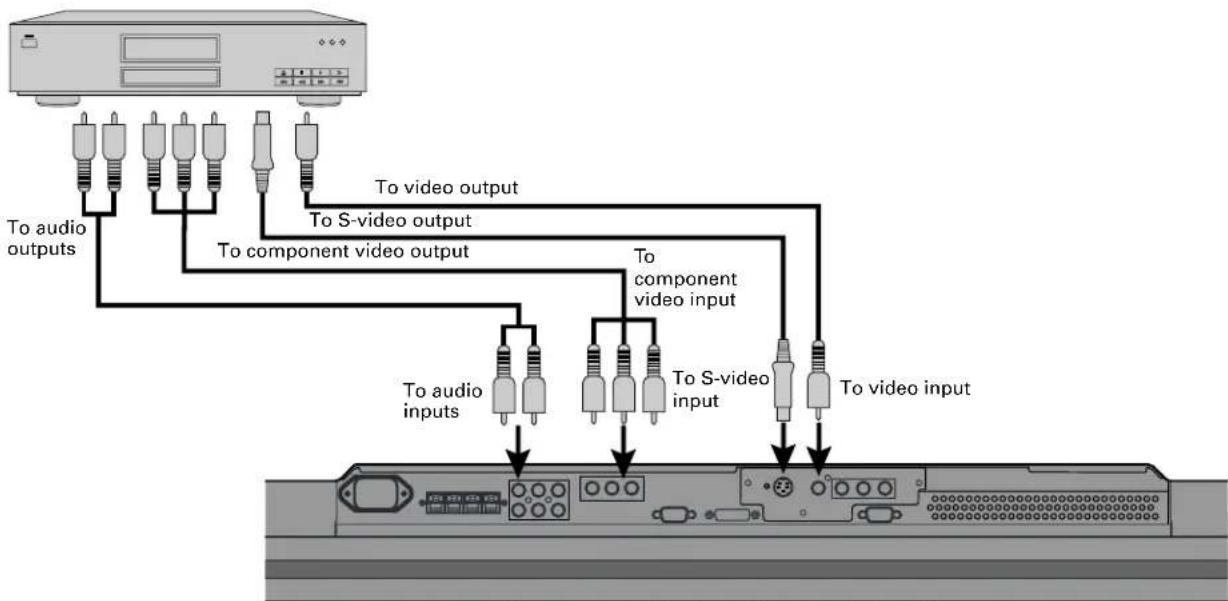
DVD PLAYER
- Connect the video signal cable to the component video input terminal, S-video input terminal, or the video input terminal. - If the component to be connected is equipped with component video output terminal, it is recommended to connect to the component video terminal.
flowchart
graph TD
    A["Audio System"] --> B["To audio outputs"]
    A --> C["To S-video output"]
    A --> D["To component video output"]
    A --> E["To audio inputs"]
    A --> F["To S-video input"]
    A --> G["To video input"]
    B --> H["Component Audio Components"]
    C --> H
    D --> H
    E --> I["Component Audio Components"]
    F --> I
    G --> I
Bottom of Display (Ex.: P42VHA10)
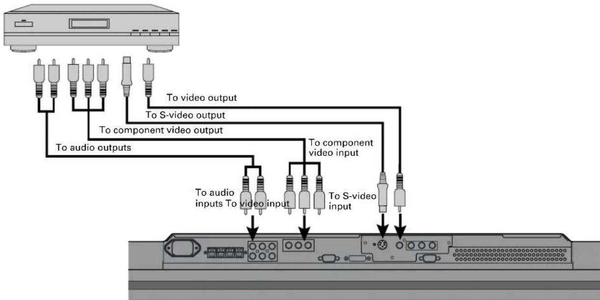
SATELLITE TUNER
- Connect the video signal cable to the component video input terminal, S-video input terminal, or the video input terminal. - If the component to be connected is equipped with component video output terminal, it is recommended to connect to the component video terminal.
flowchart
graph TD
    A["Radio Station"] --> B["To audio outputs"]
    A --> C["To video output"]
    A --> D["To S-video output"]
    A --> E["To component video output"]
    A --> F["To audio inputs To video input"]
    A --> G["To S-video inputs To video input"]
    B --> H["Internal Panel"]
    C --> H
    D --> H
    E --> H
    F --> H
    G --> H
Bottom of Display (Ex.: P42VHA10)
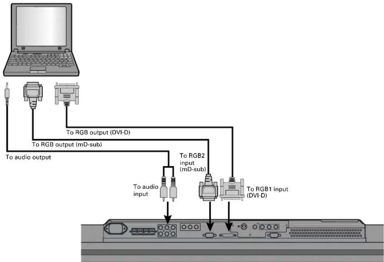
PC
- As the cable for connecting a PC differs with the PC model, please consult your dealer for information on the right cable to purchase.
- The PC can be connected to either the front side or the rear side, whichever is most convenient.
flowchart
graph TD
    A["Laptop"] --> B["To audio output"]
    A --> C["To RGB output (mD-sub)"]
    A --> D["To RGB2 input (mD-sub)"]
    A --> E["To RGB1 input (DVI-D)"]
    B --> F["To audio input"]
    C --> G["To RGB output (DVI-D)"]
    D --> H["To RGB2 input (mD-sub)"]
    E --> I["To RGB1 input (DVI-D)"]
Bottom of Display (Ex.: P42VHA10)
Note
- Unplug the power cord from the AC outlet before you connect external components.
- Also refer to the instructions for the component to be connected.
- When inputting audio, connect to the terminals corresponding to the used video input or RGB input.
* You can also use the buttons on the display's control panel to perform these steps.
1 Press ⏻ to the left at the bottom of the display to the ON ⏻ state.
The power lamp lights up.
2 Press on the remote control.
The color of the power lamp changes from "Red" to "Green".
3 Press VIDEO1 VIDEO3 RGB1 RGB2 RGB3/ VIDEO4 .
Select the video mode to be input.
Press when the power is ON.
The color of the power lamp changes from "Green" to "Red" and the power turns "OFF".
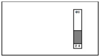
ADJUSTING THE VOLUME
Press the Volume button
Press vol to increase the volume.
Press VOL. — to reduce the volume.
Any value between 0 and 40 can be selected.
* Note that the volume level remains stored even when you turn OFF the power.
bar_stacked
| Category | Value | |---|---| | d(0) | 1 | | 2 | 3 | | 4 | 4 |When the volume adjustment button is pressed
Muting the sound

The sound is removed.
Press again to restore the sound to the original level.
The mute mode can also be released by pressing the volume buttons.
VIDEO INPUT MODE
text_image
Plasmavision W FUJITSU* You can also use the buttons on the display's control panel to perform these steps.
1
Press the - buttons to select the input mode.
You can select from VIDEO1 mode to VIDEO4 mode.
The video modes corresponding to each input terminal are as follows.
• VIDEO1: Video
• VIDEO2: S-video
• VIDEO3: Component video
• VIDEO4: Component video
* For selection of the input terminal, see "SETTING THE INPUT TERMINALS" on P. E-35.
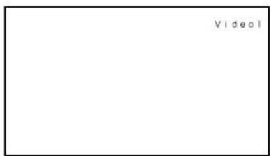
text_image
Video1Video1 mode
RGB INPUT MODE
1
Press - to select the input mode.
You can select between the modes from RGB1 to RGB2.
The input terminal of each RGB mode is as follows.
- RGB1: DVI-D
- RGB2: mD-sub
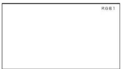
text_image
RGB 1RGB1 mode
CONVENIENT FUNCTIONS
text_image
Plasmavision W FUJITSUOn-screen information (DISPLAY)

The mode is indicated on the screen for 5 seconds.
Picture Mode (PICTURE MODE)

This button can be used to switch the picture mode.
In the picture mode, you can switch between the set status and the fine mode.
* For the picture mode settings, see "Setting Picture Mode (P. E-26)".
Picture Memory (PICTURE MEMORY)

This button can be used to recall the settings of the picture memories 1 - 8. Each time this button is pressed, the setting changes as follows.
→Memory1→Memory2→Memory3→Memory4→Memory5→Memory6→Memory7→Memory8
* For the picture memory settings, see "Picture Memory (P. E-27)".
SWITCHING BETWEEN SCREEN SIZES
text_image
Plasmavision W OFF DISPLAY MCLR MCLR MCLR MCLR MCLR MCLR MCLR MCLR MCLR MCLR MCLR MCLR MCLR MCLR MCLR MCLR MCLR MCLR MCLR MCLR MCLR MCLR MCLR MCLR MCLR MCLR MCLR MCLR MCLR MCLR MCLR MCLR MCLR MCLR* You can also use the buttons on the display's control panel to perform these steps.

Press

The currently selected mode will appear.

Press WDE to select a desired picture mode.
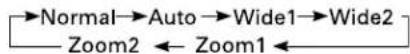
Each time you press 📄 a different picture mode appears. The sequences used are as follows:
When you are in a Video or S-video input mode
When you are in a Comp.video input mode
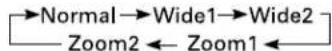
When you are in an RGB input mode

* Depending on the type of signal, some aspects may not be selected.
text_image
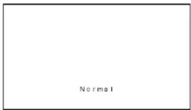
NormalNormal mode
text_image
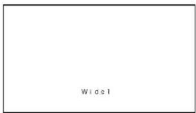
Wide1Wide1 mode
Note
- Displaying a picture in a Normal mode for extended periods of time may cause phosphor burn-in.
- A variety of picture modes are available with this display. Remember that if you select a mode with an aspect ratio (ratio of frame width to frame height) different from that of the TV program or video media, the pictures will appear differently than if you had selected a mode having the same aspect ratio.
- Showing a movie or similar premium event at a different aspect ratio from its original one at any event site, restaurant, or bar for profit-making purposes or for a public audience may constitute a copyright infringement. For films, try to select a mode having the same aspect ratio as the original picture; this enables the director's original intentions to be preserved.
Reference
See P. E-28–E-29 for how to adjust the picture size and position.
SCREEN SIZE
Normal
Displays pictures of normal size (i.e., a 4:3 aspect ratio).
Auto
The screen size changes automatically in accordance with the contents of image software you use.
Wide1
Displays natural-looking pictures of standard size on the wide screen.
Wide2/Wide
Ideal for displaying vertically extended pictures such as squeezed pictures and recorded HDTV programs.
Zoom1/Zoom
Enlarges horizontally extended pictures equally in all directions to maintain the aspect ratio constant.
Zoom2
Reduces the height of horizontally extended pictures with captions, without eliminating the caption. Only the height of pictures is reduced, not the height of the caption.
(Captions may not be easy to read, however, depending on the picture.)
Picture of standard size

Wide1
Vertically extended picture

Wide2
Horizontally extended picture

Zoom1
Horizontally extended picture with caption

Zoom2
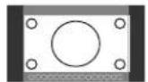
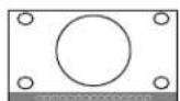
ASPECT RATIO
The following aspect ratios are available.
4:3 aspect ratio
(VHF/UHF broadcasting, BS broadcasting)

16:9 aspect ratio
(HDTV broadcasting)
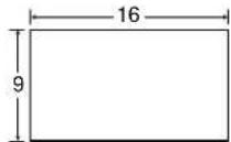
1.85:1 aspect ratio
(Vista Vision size)
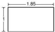
2.35:1 aspect ratio
(Cinema Vision size)
Information
You may find dark areas on top and at the bottom of the screen if you select one of the Zoom modes for media while using the Vista Vision or Cinema Vision size i.e., the sizes used frequently for picture software.
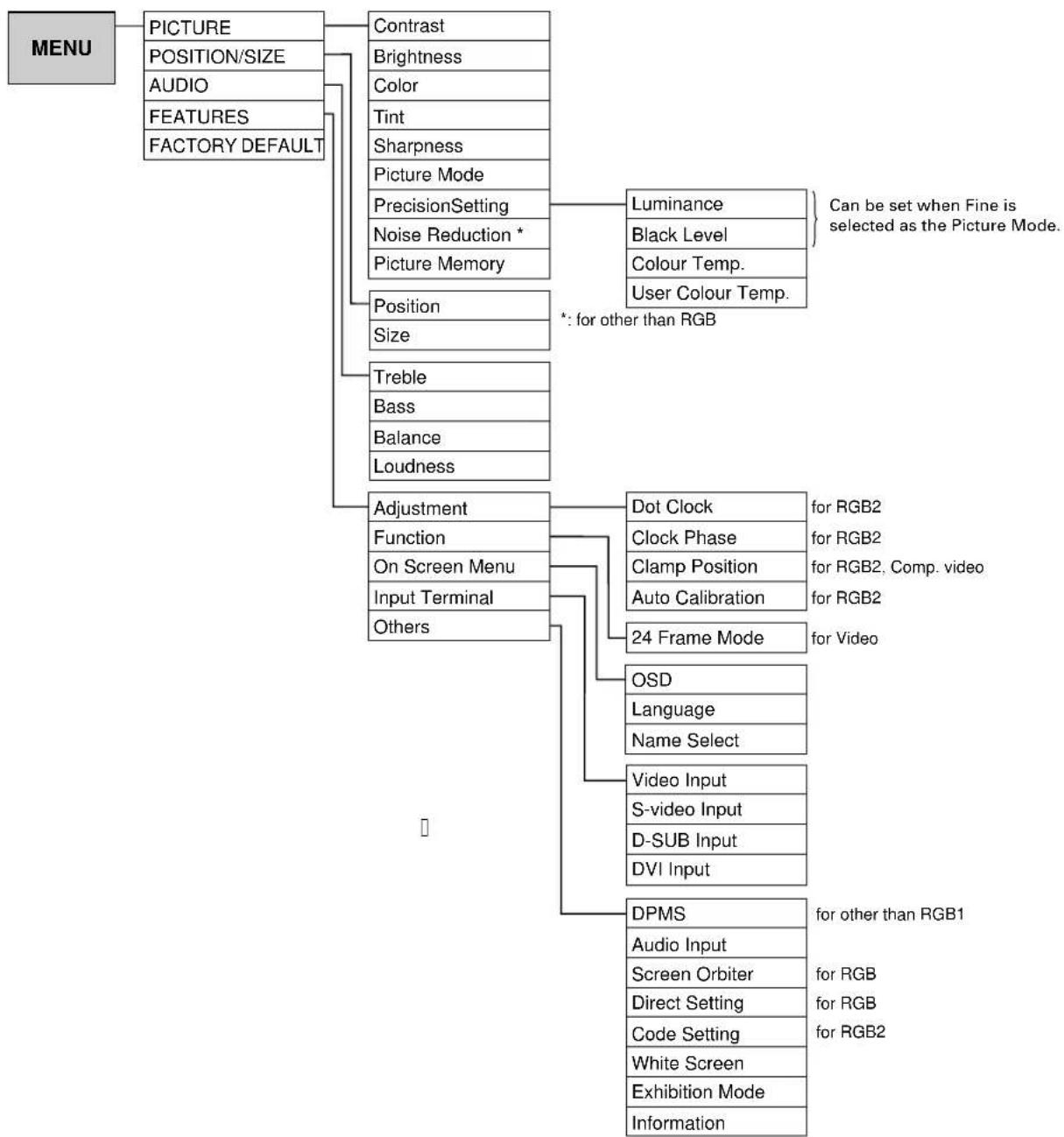
ADJUSTMENT MENU
flowchart
graph TD
    A["MENU"] --> B["PICTURE"]
    A --> C["AUDIO"]
    A --> D["FEATURES"]
    A --> E["FACTORY DEFAULT"]
    B --> F["Contrast"]
    B --> G["Brightness"]
    B --> H["Color"]
    B --> I["Tint"]
    B --> J["Sharpness"]
    B --> K["Picture Mode"]
    B --> L["PrecisionSetting"]
    B --> M["Noise Reduction *"]
    B --> N["Picture Memory"]
    E --> O["Position"]
    E --> P["Size"]
    E --> Q["Treble"]
    E --> R["Bass"]
    E --> S["Balance"]
    E --> T["Loudness"]
    E --> U["Adjustment"]
    E --> V["Function"]
    E --> W["On Screen Menu"]
    E --> X["Input Terminal"]
    E --> Y["Others"]
    F --> Z["Luminance"]
    F --> AA["Black Level"]
    F --> AB["Colour Temp."]
    F --> AC["User Colour Temp."]
    Z & AA & AB & AC & AD["*: for other than RGB"] --> AE["Can be set when Fine is selected as the Picture Mode."]
    U --> AF["Dot Clock"]
    U --> AG["Clock Phase"]
    U --> AH["Clamp Position"]
    U --> AI["Auto Calibration"]
    U --> AJ["24 Frame Mode"]
    AF & AG & AH & AI & AJ --> AK["for RGB2"]
    AG & AH & AI & AJ --> AL["for RGB2, Comp. video"]
    U --> AM["OSD"]
    U --> AN["Language"]
    U --> AO["Name Select"]
    U --> AP["Video Input"]
    U --> AQ["S-video Input"]
    U --> AR["D-SUB Input"]
    U --> AS["DVI Input"]
    U --> AT["DPMS"]
    U --> AU["Audio Input"]
    U --> AV["Screen Orbiter"]
    U --> AW["Direct Setting"]
    U --> AX["Code Setting"]
    U --> AY["White Screen"]
    U --> AZ["Exhibition Mode"]
    U --> BA["Information"]
BASIC OPERATIONS [EX.: ADJUSTING TINT (Tint)]
You can make changes to all picture adjustment options in the PICTURE Menu.
The changes you make will be stored for a selected input mode. Therefore, you need to select a desired input mode before making any changes.
![FUJITSU P50XHA10W - BASIC OPERATIONS [EX.: ADJUSTING TINT (Tint)] - 1](/content/2026/06/1199575/images/40bad4cfb3436278179811f5d4d6480aea431a6207bf517410c5e2fbab184a82.jpg)
text_image
Plasmavision W MOSE DISPLAY MEO2 MEO3 MEO4 RESET RESET RESET RESET RESET VOL + - MDU FJITSU1 Press MENU
The main menu screen will appear.
2 Press or to select "PICTURE".
Each time you press or, one of the available menus appears in the following sequence:
![FUJITSU P50XHA10W - BASIC OPERATIONS [EX.: ADJUSTING TINT (Tint)] - 2](/content/2026/06/1199575/images/323d878b05abaa9778e20720d0d2adbf98c3cd04344446abd0eb43194caa4084.jpg)
text_image
3D View PCTURE Contrast 0 Brightness 0 Color 0 Tint 0 Sarpness 0 Picture Mode Dynamic PrecisionSetting Noise Reduction Off Picture Memory Default Menu quit Enter next"PICTURE" selected in the main menu screen (Video Input Mode)
PICTURE POSITION/SIZE AUDIO FEATURES FACTORY DEFAULT The PICTURE Menu screen will appear.
3 Press or to select "Tint".
4 Press ENTER . The "Tint" adius
![FUJITSU P50XHA10W - BASIC OPERATIONS [EX.: ADJUSTING TINT (Tint)] - 3](/content/2026/06/1199575/images/fc75bed3478cab870a14bed8e96a159160e57fa9468b5ae1b0224dac2ed8990d.jpg)
text_image
STOCKS PICTURE Contrast 0 Brightness 0 Color 0 Flint 0 Sharpness 0 Picture Mode Dynamic PrecisionSetting Noise Reduction Off Picture Memory Default Menu quit Next"Tint" selected in the PICTURE Menu screen (Video Input Mode)
5 Press or to-change tint values.
: More greenish colors
: More purplish colors
6 Press ENTER to store.
Press MENU when you finish.
![FUJITSU P50XHA10W - BASIC OPERATIONS [EX.: ADJUSTING TINT (Tint)] - 4](/content/2026/06/1199575/images/87f47e654ddc8325ab91dec361fca9e8c18c6159666c542663e80f9274dbcc39.jpg)
text_image
Tint < > adjust"Tint" adjustment screen
* Repeat steps 3, 4, 5 and 6 when you wish to make changes to other options.
* When 📄 is pressed after you have selected "Default", the settings are returned to those that were valid when you purchased the set.
- Contrast, brightness, color darkness, tint, and picture sharpness are adjusted as shown in the following chart.
Select the item with ▲ ▼, and then adjust with ◆ ▶. Finally, press ENTER to implement the adjustments.
| Adjustment Item | Adjustment Range/Remarks | ||
| Contrast | Lower contrast | Higher contrast | -30 to +30 |
| Brightness | Darker screen | Brighter screen | -60 to +60 |
| Color | Lighter colors | Darker colors | -60 to +60 |
| Tint | More purplish colors | More greenish colors | -60 to +60 (RGB, Comp. video)-30 to +30 (Video, S-video) |
| Sharpness | Softer pictures | Sharper pictures | -4 to +4 (RGB)-16 to +16 (other than RGB) |
- Setting Picture Mode (Picture Mode)
Can set up the picture mode.
Each time you press ◀ or ▶one of the available choices appears in the following sequence:

Dinamic:Suitable for watching a normal motion picture.(Standard)
Fine: Suitable for watching a dark picture such as movie.
Real 1: Makes a strong contrast picture.
Real 2: Makes a bright color picture.
Static: Suitable for watching a still picture.
Press ENTER to store.
*Select Dinamic, Fine, Real 1, Real 2 or Static to suit your taste.
- Precision Setting (for more advanced adjustment)
Luminance, Black Level, Color Temperature, and User Color Temperature are adjusted as shown in the following chart.
Select the item with ▲, and then adjust with ◀. Finally, press □ to implement the adjustments.
| Adjustment Item Contents of Adjustments Operation | Adjustment Range/Remarks | ||
| Luminance | Adjusts the luminance level.(when the Picture Mode is Fine) | Useto adjust. | 40 to 100% |
| Black Level | Adjusts the picture when watching a dark image. (when the Picture Mode is Fine) | Useto adjust. | -15 to +15 |
| Color Temperature | Set to low to obtain a warm atmosphere,and set to high to obtain a cold atmosphere. | Useto adjust. | -3500 to +3500 |
| User Color Temperature | Enables individual adjustment of Red,Green and Blue. | Useto select, and use toadjust. | 0 to 255 |
- Setting Noise Reduction (Noise Reduction)
Can select the noise reduction setting corresponding to the noise level of the input signal.
Each time you press ◀ or ▶one of the available choices appears in the following sequence:

Off: Noise reduction does not function.
Min.: Weak setting
Std.: Standard setting
Max.: Strong setting
Press ☐ to store.
*Some type of signal can not be selected.
- Storing the setting of PICTURE (Picture Memory)
Stores 8 patterns of adjustments set by PICTURE.
Read out and store to suit your taste.
In case of "Load"
When setting "Load": Read out your desired Setting.
(1) Select "Picture Memory" and press ENTER.
The "Picture Memory" screen will appear.
(2) Press ▲ or to select Load.
(3) Select Data number to make Load.
(4) Press ☐ to read out.
In case of "Save"
When setting "Save": Set to suit your taste and store.
(1) Select "Picture Memory" and press ENTER.
The "Picture Memory" screen will appear.
(2) Press ◆ or ◆ to select Save.
(3) Select Data number to make Save.
(4) Press ☐ to save.
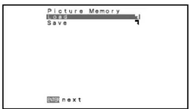
text_image
Picture Memory Home Save ENTER next"Picture Memory" selection screen
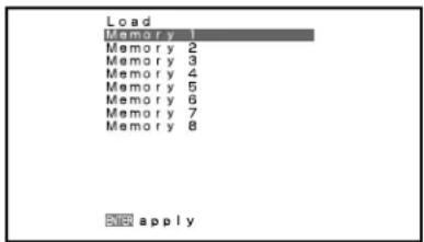
text_image
Load Memory 1 Memory 2 Memory 3 Memory 4 Memory 5 Memory 6 Memory 7 Memory 8 NEW apply"Load" selection screen
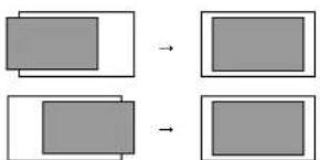
BASIC OPERATION [EX.: ADJUSTING HORIZONTAL DIRECTION OF SCREEN POSITION]
You can make changes to all screen adjustment options in the POSITION/SIZE Menu.
The changes you make will be stored for the selected input mode. Therefore, you need to select a desired input mode before making any changes.
![FUJITSU P50XHA10W - BASIC OPERATION [EX.: ADJUSTING HORIZONTAL DIRECTION OF SCREEN POSITION] - 1](/content/2026/06/1199575/images/25f935d499b9a1f725a8f95f221075d4d6ea76aee493c283f4197972562a1fcc.jpg)
text_image
Plasmavitsien W FUJITSU1 Press MENU The main menu screen will appear.
2 Press or to select "POSITION/SIZE".
Each time you press or, one of the available menus appears in the following sequence:
![FUJITSU P50XHA10W - BASIC OPERATION [EX.: ADJUSTING HORIZONTAL DIRECTION OF SCREEN POSITION] - 2](/content/2026/06/1199575/images/c516931ad248d2fc2dc13db0fe8efd76f5925c192f2a6ec98447a95030da839e.jpg)
text_image
POSITION/SIZE Position Size Default MOUT NOT next"POSITION/SIZE" selected from the main menu screen
PICTURE POSITION/SIZE AUDIO FEATURES FACTORY DEFAULT
The POSITION/SIZE Menu screen will appear.
3 Press on to select "Position".
4 Press ENTER. The "Position" a
5 Press, ▲ or to change position values.
: Moves screen up.
: Moves screen down.
: Moves screen to the right.
: Moves screen to the left.
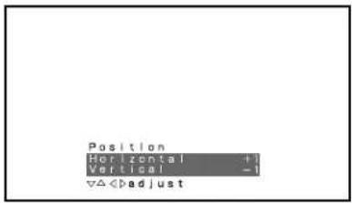
![FUJITSU P50XHA10W - BASIC OPERATION [EX.: ADJUSTING HORIZONTAL DIRECTION OF SCREEN POSITION] - 3](/content/2026/06/1199575/images/bac80868fcf78906d1c42d024b7ec758ec68fbd42155857bbe24ad0b13757d3d.jpg)
text_image
Position Horizontal 0 Vertical 0 ▼Adjust"Position" adjustment screen
6 Press ENTER to store.
Press MENU when you finish.
* Repeat steps 3 to 6 when you wish to make changes to other options.
* When is pressed after you have selected "Default", the settings are returned to those that were valid when you purchased the set.
Adjusting Screen Position (Position)
Horizontal position (Horizontal)
: Moves screen to the right.
: Moves screen to the left.
Vertical position (Vertical)
: Moves screen up.
: Moves screen down.
Press to store.
flowchart
graph TD
    A["Rectangle"] --> B["Rectangle"]
    C["Rectangle"] --> D["Rectangle"]
flowchart
graph TD
    A["Step 1"] --> B["Step 2"]
    B --> C["Final Step"]
text_image
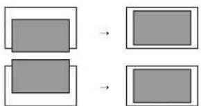
Position Horizontal +1 Vertical -1 ∇ΔAdjusting Screen Size (Size)
Screen width (Width) : Increases width. : Reduces width. Screen height (Height) : Increases height. : Reduces height. flowchart
graph TD
    A["Rectangle with one smaller rectangle"] --> B["Rectangle with one larger rectangle"]
    B --> C["Rectangle with one smaller rectangle"]
flowchart
graph TD
    A["Rectangle"] --> B["Rectangle"]
    C["Rectangle"] --> D["Rectangle"]
text_image
Size Width +1 Height -1 adjustSetting Range
| Video, S-video mode | Comp.video mode | RGB mode | |
| Position | Horizontal: -30 to +30VerticalZoom: -15 to +15Others: -7 to +7 | -16 to +16 | -150 to +150 |
| Size | -3 to +12 (P42HHA10)-7 to +16 (P42VHA10/20)-7 to +12 (P50XHA10) | -2 to +16 (P42HHA10)-4 to +20 (P42VHA10/20)-4 to +16 (P50XHA10) | -12 to +25 (P42HHA10)-25 to +50 (P42VHA10/P50XHA10/P42VHA20) |
BASIC OPERATION [EX.: ADJUSTING VOLUME BALANCE (Balance)]
You can make changes to all sound adjustment options in the AUDIO Menu. The changes you make will be stored for the selected input mode. Therefore, you need to select a desired input mode before making any changes. text_image
Plasmavision W MUS DISPLAY HOLD SLIGHT HOLD MUS HOLD SLIGHT HOLD MUS HOLD SLIGHT VOL + - MENU FJITSUtext_image
AUDIO Cable 0 Bass 0 Balance 0 Loudness Off OK quit OK nexttext_image
AUDIO Treble 0 Bass 0 Balance 0 Loudness Off < > adjustAdjusting Treble (Treble)
Any value between -6 and +6 can be selected. : Stronger treble : Weaker trebleAdjusting Bass (Bass)
Any value between -6 and +6 can be selected. : Stronger bass : Weaker bassAdjusting Volume Balance (Balance)
Any value between -10 and +10 can be selected. : Higher volume from the right-hand speaker : Higher volume from the left-hand speakerSetting Loudness (Loudness)
Corrects the balance between bass and treble for easy listening even with weak volume. Each time you press ◀ or ▶one of the available choices appears in the following sequence: On Off On : Corrects bass and treble. Off : Loudness dose not function. text_image
AUDIO Enable 0 Bass 0 Balance 0 Loudness Off < > adjustBASIC OPERATION [EX.: SELECTING LANGUAGE (Language)]
You can make the following changes in the FEATURES Menu. text_image
Plasmavision W M. DE DISPLAY MO FOR USE MO FOR USE MO FOR USE MO FOR USE MO FOR USE MO FOR USE MO FOR USE MO FOR USE MO FOR USE MO FOR USE MO FOR USE MO FOR USE MO FOR USE MO FOR USE MO FOR USE MO FOR USE MO FOR USE MO FOR USE MO FOR USE MO FOR USE MO FOR USE MO FOR USE MO FOR USE MO FOR USE MO FOR USE MO FOR Use MO FOR USE MO FOR USE MO FOR USE MO FOR USE MO FOR USE MO FOR USE MO FOR USE MO FOR USE MO FOR USE MO FOR USE MO FOR USE MO FOR USE MO FOR USE MO FOR USE MO FOR USE MO FOR USE MO FOR USE MO FOR USE MO FOR USE MO FOR USE MO FOR USE MO FOR USE MO FOR USE MO FOR USE MO FOR UTRU MO FOR UTRU MO FOR UTRU MO FOR UTRU MO FOR UTRU MO FOR UTRU MO FOR UTRU MO FOR UTRU MO FOR UTRU MO FOR UTRU MO FOR UTRU MO FOR UTRU MO FOR UTRU MO FOR UTRU MO FOR UTRU MO FOR UTRU MO FOR UTRU MO FOR VOUT MO FOR VOUT MO FOR VOUT MO FOR VOUT MO FOR VOUT MO FOR VOUT MO FOR VOUT MO FOR VOUT MO FOR VOUT MO FOR VOUT MO FOR VOUT MO FOR VOUT MO FOR VOUT MO FOR VOUT MO FOR VOUT MO FOR VOUT MO FOR VOUTtext_image
FEATURES On Screen Menu Input Terminal Others More adjustment items included in this menu. MENU quit ENTER nexttext_image
On Screen Menu USU On (QSD Bright) Language Name Select <> selecttext_image
Language 日本語 English Deutsch Español Français Italiano Português apply- FEATURES setup screen has the following 5 options.
Adjustment : Can make a fine adjustment of pictures such as Dot Clock, Clamp Position. Function : Allows setting of 24-frame mode. (See P. E-34.) On Screen Menu : Can make a display setting such as OSD, Language. (See P. E-34.) Input Terminal: Can make an input terminal setting such as Video Input. (See P. E-35.) Others : Can make other settings. (See P. E-36–E-38.)ADJUSTMENT
Dot Clock, Clock Phase, Clamp Position, and Auto Calibration are adjusted as shown in the following chart.
Select the item with ▲ ▼, and then adjust with ◀. Finally, press □ to implement the adjustments.| Adjustment Item | Contents of Adjustments Operation | Adjustment Range/Remarks | |
| Dot Clock (RGB2) | You may find that pictures blur, depending on the clock frequency of your PC’s processor. If you experience blurring, you can obtain a clearer picture by adjusting the “Dot Clock”. | Use ➔ ➔ to select the optimal value at which blurring of pictures is eliminated. | -60 to +60 |
| Clock Phase (RGB2) | Pictures may blur as the clock phase of your PC may be different. In this case, adjust the clock phase manually. Normally, the automatic setting ensures the optimal value. | Use ➔ ➔ to select the optimal value at which blurring of pictures is eliminated. | Auto/Manual Manual: 1 to 32 |
| Clamp Position (RGB2, Comp. video) | Adjusts the clamp position in accordance with the input signal received from connected equipment. Normally, the automatic setting ensures the optimal value. | Use ➔ ➔ to select the optimal value. | -8 to +8 |
| Auto Calibration (RGB2) | Adjusts the dynamic range of images to the optimum. Performed while a white screen signal is received. | Display the Auto Calibration screen and select Execute, and then use ➔ ➔ ➔ to select the item. | Execute/Cancel |
FUNCTION
- Displaying the optimum movie pictures (24 Frame Mode) for Video
Can make the optimum display of 24 frames/second signals such as movie pictures. Each time you press ◀ or ▶one of the available choices appears in the following sequence:On ←→ Off
ON SCREEN MENU
- Setting Display Information (OSD)
You can use this option to select whether to display information other than menus. (Error messages are displayed regardless of what choice you make for this option.) Each time you press or one of the available choices appears in the following sequence:  On (OSD:bright): On-screen information shown in light color. On (OSD:dark): On-screen information shown in dark color. Off: Except for menus and error messages, on-screen information is not displayed. Press ENTER to store.- Selecting Language (Language)
You can use this option to select the language displayed on the screen. (1) Select "Language" and press ENTER. The "Language" selection screen will appear. (2) Press ▲ or ▲ to select your desired language. 日本語 (Japanese) English Deutsch (German) Español (Spanish) Français (French) Italiano (Italian) Português (Portuguese) (3) Press ENTER. The menu is displayed in the selected language.• Selection of indications
You can change the settings for indications for video inputs and RGB inputs.Video input
You can change the settings for indications for the VIDEO inputs. Select the desired indication in accordance with the connected equipment. Each time is pressed, the setting is switched. (In the case of VIDEO1)  Press ENTER to store.RGB input
You can change the settings for indications for the RGB inputs. Select the desired indication in accordance with the connected equipment. Each time ▶ is pressed, the setting is switched. (In the case of RGB 1)  Press ENTER to store. text_image
On Screen Menu OSD On (OSD bright) Language Name Select <> selecttext_image
Language 日本語 English Deutsch Español Français Italiano Português ENTER applySETTING THE INPUT TERMINALS
- Selecting Video Mode (Video Input)
You can use this option to select the desired video mode of pictures it will receive to the Video Input terminal. Each time you press 🔔 or 🔖 one of the available modes appears in the following sequence:  Auto1: Automatically selects NTSC, PAL and SECAM. Auto2: Automatically selects NTSC and M-PAL. Other than Auto: You need to select a system appropriate to the input signal. Press ☐ to store.- Selecting S-video Mode (S-video Input)
You can use this option to select the desired video mode of pictures it will receive to the Video Input terminal. Each time you press 🔒 or 🔒 one of the available modes appears in the following sequence:  Auto1: Automatically selects NTSC, PAL and SECAM. Auto2: Automatically selects NTSC and M-PAL. Other than Auto: You need to select a system appropriate to the input signal. Press ☐ to store.- Selecting D-SUB Input (D-SUB Input)
You can use this option to select the signal system it will receive to D-SUB Input terminal. (1) Select D-SUB Input and press ENTER. D-SUB Input screen appears. (2) Select the signal system to receive. Each time you press 🔒 or 🔒 one of the available choices appears in the following sequence: RGB-PC ↔ Decoder RGB-PC: For using RGB for PC Decoder: For using digital broadcast tuner (3) Press ▲ or to select Mask. (4) Select Decoder by FUNCTION to set up Mask. Each time you press ◆ or ▶one of the available choices appears in the following sequence:  Off: Does not mask. Number: Masks the fringe (top, bottom, right and left) of the screen by the number of pixels specified. (5) Press 📋 to store.• DVI Input
You can select the signal method input to the DVI input terminal. Each time or is pressed, the setting is changed. DVI1 ←→ DVI2 DVII: Used when connecting to a PC. DVI2: Used when connecting to a DVD player or digital tuner. Press ENTER to store. \* Set according to the signal method before connecting peripheral device. text_image
D-SUB Input Function RGB-PC <> selectnatural_image
Empty rectangular frame with diagonal hatching, no text or symbols presentOTHER SETTINGS
DPMS for other then RGB1
You can use this option to select the amount of time before the DPMS function starts. DPMS (which stands for “display power management signaling”) allows the display to maintain an automatic power saving function. This function causes on-screen information to disappear until the next input operation, if the power is ON and the display has not received any signals for the predetermined period of time. When DPMS is active, the power indicator lamp turns orange. (1) Select DPMS and press ENTER. DPMS screen appears. (2) Press or to select Time. (3) Each time you press or one of the available choices appears in the following sequence:  Off: Disables DPMS Number: Approximate time before DPMS starts. (Unit: minutes) \* The power indicator lamp turns orange while the DPMS is ON. \* The power turns ON automatically when the display receives a signal. (4) Can specify background colour. Press ▲ or to select background colour. Each time you press ◀ or ▶ one of the available choices appears in the following sequence: Black White Black: Mutes images in Black background. White:Mutes images in White background. \* Switches approx. 20 seconds after the display stops receiving signals. (5) Press ENTER to store.- Selecting input terminals (Audio Input)
You can use this option to select one of the three available terminals to receive sound from input equipment. (1) Select "Audio Input" and press 📄. The "Audio Input" selection screen will appear. (2) Press ▲ or to select input equipment. (3) Select a desired input terminal. Each time you press ◀ or ▶ one of the available choices appears in the following sequence:  No audio: No sound in the corresponding mode. Audio 1-3: Selects Audio 1 through 3 for receiving sound in the corresponding mode. \* Repeat steps (2) and (3) for each piece of input equipment. (4) Press ☐ to store. \*Audio Input menu will not be displayed when "No Audio" is selected. text_image
DPMS Name Off Background Break <=> selecttext_image
Audio Input RGB1 Audio1 RGB2 Audio1 Video1 Audio2 Video2 Audio2 Video3 Audio3 Video4 Audio3 <-> selectMinimizing
phosphor
You can use this option to move the screen position to minimize phosphor-induced "burn-in". Follow the steps below. (1) Select "Screen Orbiter" and press ENTER. The "Screen Orbiter" setting screen will appear. (2) Press ▲ or to select "Mode/Time". (3) Select a desired pattern. Each time you press ◀ or ▶ one of the available choices appears in the following sequence:  Off: Disables Screen Orbiter. Time: Moves the pattern approximately every one hour. Mode: Moves the pattern when the power is turned ON or when you switch between modes. (4) Press ▲ or to select "Moving Area". (5) Press ◀ or ▶ to select the range for moving the pattern. Each time you press ◆ or ▶one of the available choices appears in the following sequence:  Min.: Pattern moves in small range. (About 5 pixels) Std.: Pattern moves in moderate range. (About 10 pixels) Max.: Pattern moves in wide range. (About 15 pixels) (6) Press ☐ to store. \* When the Screen Orbiter function is operated in RGB1 mode, some letters at the top, bottom, right or left of the screen may be missed. text_image
burnain Orbiter Mode/time Off Moving Area Std. <> SelectSetting
RGB
Input
Signal
Compulsorily
(Direct
You can use this option to switch the setting for RGB input signal. Each time you press ◀ or ▶one of the available choices appears in the following sequence: For RGB1 mode:  For RGB2 mode:  Auto: The optimum display is obtained automatically for input signals. Others: The optimum resolution setting is fixed for each signal. Press ☐ to store. \* In Auto mode, the resolution of VGA, WVGA, 480P, XGA, WXGA, SXGA and SXGA may not be automatically distinguished. Switch to the fixed display when the image is not displayed properly.OTHER ADJUSTMENTS (FEATURES MENU) (Continued)
Specifying
RGB
You can use this option to specify and display the type of RGB input signal by code number. Each time you press ◀ or ▶ one of the available choices appears in the following sequence: Auto ↔ Manual Auto: Automatically displays the input signal to the optimum. Manual: Selects RGB code number. Press ENTER to store. \* In Auto mode, the optimum resolution may not be set up automatically depending on the type of signal. Select the type of signal when the image is not displayed properly. However, note that when the type of signal is selected directly, the signal of other resolution may not be displayed properly.- Displaying white over entire screen (White Screen)
You can use this option to display white over the entire screen to minimize phosphor burn-in. Each time you press ◀ or ▶one of the available choices appears in the following sequence: On ←→ Off Off: Does not display white. On: Displays a white screen immediately. Press ENTER to store.- Setting Exhibition Mode (Exhibition Mode)
You can use this option to display the enhanced contrast, which is most suitable for the use by unspecified persons. Each time you press ◀ or ▶one of the available choices appears in the following sequence: On Off On: Sets up Exhibition mode. Off: Sets up normal mode. Press ENTER to store. \* In Exhibition mode, the display returns to the original setting in about 5 minutes even if the adjustment is changed. \* The setup will be cancelled when removing the power plug from the receptacle.- Displaying System Status (Information)
Displays system operation status. Select "Information" and press ENTER. The "Information" screen will appear. Mode: Input mode appears at the upper right corner of the screen. Freq. Scan Mode: Frequency scanning Input Signal: Video mode Input Sync.: Signal type Freq.: Frequency and polarity (fH, fV) Preset No.: RGB code number text_image
Input de Setting Auto Manual 0.2 Signal ENTER applytext_image
Information Mode Freq. Scan Video Input Signal Auto Freq. NTSC fix 15.7KHz/- fv $0.0 Hz/-text_image
Information Mode Freq. Scan Mode Input Sync Auto Separate Freq. fH 37.9KHz/+ fV 60.5 Hz/+ Preset: No. 18text_image
Plasmavision W MENU DISPLAY MOSI MOSO MOSO MENU MENU MENU MENU MENU MENU MENU MENU MENU MENU MENU MENU MENU MENU MENU MENU MENU MENU MENU MENU MENU MENU MENU MENU MENU MENU MENU MENU MENU MENU MENU MENU MENU MENU MENU MENU MENU MENU MENU MENU MENU MENU MENU MENU MENU MENU MENU MENU MENU MENU Fijiitsutext_image
改可办 FACTORY DEFAULT Execute MEN quit Enter nexttext_image
FACTORY DEFAULT Yes No Adjust and Existing data will be cleared. ENTER returntext_image
EXTRON FACTORY DEFAULT Execute Existing data are cleared. Next quit Enter nextWarning
To prevent injury, fire, and electric shock, arrange for options to be initially installed (or installed at a different location) by your dealer. CAUTION: This display (P42VHA10/P42HHA10/P50XHA10/P42VHA20) is for use only with Fujitsu General Limited's option (P-WB4200, P-CT4200, P-TT4200). Using this display with other option can cause instability resulting in possible injury. This display can store the latest four types of signals for RGB adjustment value. The fifth input signal will replace the adjustment value of the first input signal. To do this, select a desired signal and follow the instructions in “Adjusting Screen Position and Size” on P. E-28–E-29 to adjust the parameters. When you finish, the settings will be automatically stored. Thus, when the display receives that signal, pictures will be displayed in accordance with the settings you most recently selected. Main corresponding signals (RGB mode)| Display (dots x lines) | Horizontal frequency (kHz) | Vertical frequency (Hz) | Signal | DVI-D |
| 640 x 480 31.47 59.94 VGA | ○ | |||
| 640 x 480 37.50 75.00 VGA 75 Hz | ||||
| 640 x 480 43.27 85.01 VGA 85 Hz | ||||
| 720 x 400 31.47 70.09 400 lines | ○ | |||
| 800 x 600 37.88 60.32 SVGA 60 Hz | ○ | |||
| 800 x 600 46.88 75.00 SVGA 75 Hz | ||||
| 800 x 600 53.67 85.06 SVGA 85 Hz | ||||
| 1024 x 768 48.36 60.00 XGA 60 Hz | ○ | |||
| 1024 x 768 60.02 75.03 XGA 75 Hz | ||||
| 1024 x 768 68.68 84.99 XGA 85 Hz | ||||
| 1280 x 1024 63.98 60.02 SXGA 60 Hz | ||||
| 1280 x 1024 79.98 75.03 SXGA 75 Hz | ||||
| 1600 x 1200 75.00 60.00 UXGA 60 Hz | ||||
| 1600 x 1200 106.25 85.00 UXGA 85 Hz | ||||
| 848 x 480 31.02 60.00 | ○ | |||
| 852 x 480 31.72 59.97 | ||||
| 1360 x 768 47.71 60.01 | ||||
| 720 x 485 15.73 59.94 60 fields | ||||
| 720 x 575 15.63 50.00 50 fields |
| Horizontal frequency (kHz) | Vertical frequency (Hz) | Signal |
| 15.73 59.94 SDTV 480I | ||
| 15.63 50.00 SDTV 576I | ||
| 31.47 59.94 SDTV 480P | ||
| 31.25 50.00 SDTV 576P | ||
| 45.00 60.00 HDTV 720P | ||
| 37.50 50.00 HDTV 720P | ||
| 33.75 60.00 HDTV 1080I | ||
| 28.13 50.00 HDTV 1080I |
| Horizontal frequency (kHz) | Vertical frequency (Hz) | Signal |
| 15.73 59.94 NTSC | ||
| 15.63 50.00 PAL | ||
| 15.63 50.00 SECAM | ||
| 15.63 59.52 PAL60 | ||
| 15.63 50.00 N-PAL | ||
| 15.73 59.95 M-PAL | ||
| 15.73 59.94 4.43NTSC | ||
| Model P42VHA10W/P42VHA10 | 10A P42HHA10W/P42HHA10A | |
| Screen size 42" wide screen: 42" wide | 92.1 cm (W) x 51.8 cm (H) (105.7 cm diagonal) 92.236.3 inch (W) x 20.4 inch (H) (41.6 inch diagonal) | cm (W) x 52.2 cm (H) (106.0 cm diagonal)36.3 inch (W) x 20.6 inch (H) (41.7 inch diagonal) |
| Aspect ratio 16:9 (wide) | ||
| Weight 28.5 kg / 62.8 lbs | ||
| Outer dimensions 103.7 (W) x 64.2 | (H) x 8.5 (D) cm40.8 (W) x 25.3 (H) x 3.3 (D) inch | |
| Power supply 110-240 VAC 50/60 Hz | ||
| Current rating 3.1-1.4 A 4.4-1.9 A | ||
| Number of pixels 852 (H) x 480 (V) | 1024 (H) x 1024 (V) | |
| Display modes | Video, S-video input: Normal/Auto/Wide1/Wide2/Zoom1/Zoom2 | |
| Component video input: Normal/Wide1/Wide2/Zoom1/Zoom2 | ||
| RGB: Normal/Wide/Zoom | ||
| Colors | 16.77 million | |
| External equipment terminals | ||
| Video input terminals | VIDEO1 INPUT (Video input) 1 RCA terminal 1 Vp-p/75 Ω | |
| VIDEO2 INPUT (S-video input) 1 S terminal Y: 1 Vp-p/75 ΩC: 0.286 Vp-p/75 Ω | ||
| VIDEO3/VIDEO4 INPUT 3 RCA terminals Y: 1 Vp-p/75 Ω(Component video input) PB/CB: 0.7 Vp-p/75 ΩPR/CR: 0.7 Vp-p/75 Ω | ||
| Applicable systems | NTSC/PAL/SECAM/PAL60/N-PAL/M-PAL/4.43NTSC | |
| PC input terminal | RGB1 input 1 DVI-D terminal (EIA/CEA-861 Compliant)RGB2 input mD-sub, 3 rows, 15-pinPicture signal: 0.7 Vp-p/75 ΩSynchronization signal:TTL level | |
| Sound terminals | 2 sound input pin jacks (L/R) (3 lines)500 mVrms/at least 22 kΩ | |
| Control terminal | 1 RS-232C connector (D-sub 9-pin) | |
| External speaker output terminal | Effective max. output: 20 W + 20 W (EIAJ), 4 Ω | |
| Operating conditions | Temperature: 0 to 40 °C / 32 to 104 °FHumidity: 20 to 80 % | |
| Accessories | 1 remote control, 2AA batteries, 1 instruction manual, 1 power cable, 2 big ferrite cores,2 small ferrite cores | |
Regulation --- P42VHA10W
\- UL, CSA Safety: UL6500, C-UL EMC: FCC Part 15 Class A, ICES-003 Class A \- CE Safety: EN60065 EMC: EN55022 1998, Class A EN61000-3-2 1995 EN61000-3-3 1995 EN55024 1998 EN61000-4-2 1995 EN61000-4-3 1996 EN61000-4-4 1995 EN61000-4-5 1995 EN61000-4-6 1996 EN61000-4-8 1993 EN61000-4-11 1994 • AS Safety: IEC60065 EMC: AS/NZS 3548Regulation --- P42VHA10A/P42HHA10W/P42HHA10A
\- UL, CSA Safety: UL6500, C-UL EMC: FCC Part 15 Class B, ICES-003 Class B \- CE Safety: EN60065 EMC: EN55022 1998, Class B EN61000-3-2 1995 EN61000-3-3 1995 EN55024 1998 EN61000-4-2 1995 EN61000-4-3 1996 EN61000-4-4 1995 EN61000-4-5 1995 EN61000-4-6 1996 EN61000-4-8 1993 EN61000-4-11 1994 • AS Safety: IEC60065 EMC: AS/NZS 3548| Model P50XHA10W/P50XHA10A P50XHA10U | ||
| Screen size 50" wide screen: | 110.6 cm (W) x 62.2 cm (H) (126.9 cm diagonal)43.5 inch (W) x 24.5 inch (H) (50.0 inch diagonal) | |
| Aspect ratio 16:9 (wide) | ||
| Weight 45.0 kg / 99.2 lbs | ||
| Outer dimensions 121.4 (W) x 72.8 | (H) x 9.8 (D) cm47.8 (W) x 28.7 (H) x 3.9 (D) inch | |
| Power supply 220–240 VAC 50/60 Hz | Hz 120 VAC 50/60 Hz | |
| Current rating 2.7–2.0 A 4.9 A | ||
| Number of pixels | 1366 (H) x 768 (V) | |
| Display modes | Video, S-video input: Normal/Auto/Wide1/Wide2/Zoom1/Zoom2 | |
| Component video input: Normal/Wide1/Wide2/Zoom1/Zoom2 | ||
| RGB: Normal/Wide/Zoom | ||
| Colors | 16.77 million | |
| External equipment terminals | ||
| Video input terminals | VIDEO1 INPUT (Video input) 1 RCA terminal 1 Vp-p/75 Ω | |
| VIDEO2 INPUT(S-video input) 1 S terminal Y: 1 Vp-p/75 ΩC: 0.286 Vp-p/75 Ω | ||
| VIDEO3/VIDEO4 INPUT 3 RCA terminals Y: 1 Vp-p/75 Ω(Component video input) PB/CB: 0.7 Vp-p/75 ΩPR/CR: 0.7 Vp-p/75 Ω | ||
| Applicable systems | NTSC/PAL/SECAM/PAL60/N-PAL/M-PAL/4.43NTSC | |
| PC input terminal | RGB1 input 1 DVI-D terminal (EIA/CEA-861 Compliant)RGB2 input mD-sub, 3 rows, 15-pinPicture signal: 0.7 Vp-p/75 ΩSynchronization signal:TTL level | |
| Sound terminals | 2 sound input pin jacks (L/R) (3 lines)500 mVrms/at least 22 kΩ | |
| Control terminal | 1 RS-232C connector (D-sub 9-pin) | |
| External speaker output terminal | Effective max. output: 12 W + 12 W (EIAJ), 6 Ω | |
| Operating conditions | Temperature: 0 to 40 °C / 32 to 104 °FHumidity: 20 to 80 % | |
| Accessories | 1 remote control, 2AA batteries, 1 instruction manual, 1 power cable, 2 big ferrite cores,2 small ferrite cores | |
Regulation --- P50XHA10W
• UL, CSA Safety: UL6500, C-UL EMC: FCC Part 15 Class A, ICES-003 Class A \- CE Safety: EN60065 EMC: EN55022 1998, Class A EN61000-3-2 1995 EN61000-3-3 1995 EN55024 1998 EN61000-4-2 1995 EN61000-4-3 1996 EN61000-4-4 1995 EN61000-4-5 1995 EN61000-4-6 1996 EN61000-4-8 1993 EN61000-4-11 1994 • AS Safety: IEC60065 EMC: AS/NZS 3548Regulation --- P50XHA10A/P50XHA10U
• UL, CSA Safety: UL6500, C-UL EMC: FCC Part 15 Class B, ICES-003 Class B \- CE Safety: EN60065 EMC: EN55022 1998, Class B EN61000-3-2 1995 EN61000-3-3 1995 EN55024 1998 EN61000-4-2 1995 EN61000-4-3 1996 EN61000-4-4 1995 EN61000-4-5 1995 EN61000-4-6 1996 EN61000-4-8 1993 EN61000-4-11 1994 • AS Safety: IEC60065 EMC: AS/NZS 3548 - Specifications and external appearance may be change for the sake of improvement. - Plasmavision is a worldwide trademark of Fujitsu General Limited and is a registered trademark in Japan, the U.S.A. and other countries or areas.| Model P42VHA20W/P42VHA20A P42VHA20U | ||
| Screen size 42" wide screen: | 92.0 cm (W) x 51.8 cm (H) (106.0 cm diagonal)36.2 inch (W) x 20.4 inch (H) (41.7 inch diagonal) | |
| Aspect ratio 16:9 (wide) | ||
| Weight 29.5 kg / 65.0 lbs | ||
| Outer dimensions 103.7 (W) x 64.2 | (H) x 8.5 (D) cm40.8 (W) x 25.3 (H) x 3.3 (D) inch | |
| Power supply 220–240 VAC 50/60 Hz | Hz 120 VAC 50/60 Hz | |
| Current rating 1.8–1.5 A 4.3 A | ||
| Number of pixels | 852 (H) x 480 (V) | |
| Display modes | Video, S-video input: Normal/Auto/Wide1/Wide2/Zoom1/Zoom2 | |
| Component video input: Normal/Wide1/Wide2/Zoom1/Zoom2 | ||
| RGB: Normal/Wide/Zoom | ||
| Colors | 16.77 million | |
| External equipment terminals | ||
| Video input terminals | VIDEO1 INPUT (Video input) 1 RCA terminal 1 Vp-p/75 Ω | |
| VIDEO2 INPUT(S-video input) 1 S terminal Y: 1 Vp-p/75 ΩC: 0.286 Vp-p/75 Ω | ||
| VIDEO3/VIDEO4 INPUT 3 RCA terminals Y: 1 Vp-p/75 Ω(PB/CB: 0.7 Vp-p/75 ΩPR/CR: 0.7 Vp-p/75 Ω | ||
| Applicable systems | NTSC/PAL/SECAM/PAL60/N-PAL/M-PAL/4.43NTSC | |
| PC input terminal | RGB1 input 1 DVI-D terminal (EIA/CEA-861 Compliant)RGB2 input mD-sub, 3 rows, 15-pinPicture signal: 0.7 Vp-p/75 ΩSynchronization signal:TTL level | |
| Sound terminals | 2 sound input pin jacks (L/R) (3 lines)500 mVrms/at least 22 kΩ | |
| Control terminal | 1 RS-232C connector (D-sub 9-pin) | |
| External speaker output terminal | Effective max. output: 12 W + 12 W (EIAJ), 6 Ω | |
| Operating conditions | Temperature: 0 to 40 °C / 32 to 104 °FHumidity: 20 to 80 % | |
| Accessories | 1 remote control, 2AA batteries, 1 instruction manual, 1 power cable, 2 big ferrite cores,2 small ferrite cores | |
Regulation --- P42VHA20W/P42VHA20A
\- UL, CSA Safety: UL6500, C-UL EMC: FCC Part 15 Class B, ICES-003 Class B \- CE Safety: EN60065 EMC: EN55022 1998, Class B EN61000-3-2 1995 EN01000 3 2 1995 EN61000 3 2 1995 EN61000-3-3 1995 EN55024 1998 EN61000 4 2 1005 EN61000-4-2 1993 EN61000-4-3 1996 EN61000 4 4 1005 EN61000-4-4 1995 EN61000-4-5 1995 EN61000-4-6 1996 EN61000 4 0 1990 EN61000-4-8 1993 EN61000-4-11 1994 • AS Safety: IEC60065 EMC: AS/NZS 3548Regulation --- P42VHA20U
\- UL, CSA Safety: UL6500, C-UL EMC: FCC Part 15 Class B, ICES-003 Class B \- CE Safety: EN60065 EMC: EN55022 1998, Class B EN61000-3-2 1995 EN61000-3-3 1995 EN55024 1998 EN61000-4-2 1995 EN61000-4-3 1996 EN61000-4-4 1995 EN61000-4-5 1995 EN61000-4-6 1996 EN61000-4-8 1993 EN61000-4-11 1994 • AS Safety: IEC60065 EMC: AS/NZS 3548 - Specifications and external appearance may be change for the sake of improvement. - Plasmavision is a worldwide trademark of Fujitsu General Limited and is a registered trademark in Japan, the U.S.A. and other countries or areas.Precautions
Be sure to remove the power plug from the receptacle before cleaning the display. Be sure not to clean the display using a cloth dampened with volatile solvents, such as benzene or thinner. Such solvents can harm the display's cabinet, the filter at the screen front, and the remote control. They can also cause paint to come off these sections.Cleaning the Screen
Clean the screen gently with a soft cloth. The screen surface is fragile. Never attempt to clean it with a hard material, press on it forcefully, or tap it.Cleaning the Cabinet and Remote Control
Use a soft cloth for cleaning. If the cabinet or remote control is heavily stained, soak a soft cloth in a mixture of water and detergent and squeeze it dry before wiping off the stains. Use a soft, dry cloth for final cleaning.Cleaning the ventilation grille
Remove dust from the ventilation grille in the rear of the main unit periodically with a vacuum cleaner as the accumulated dust can increase the internal temperature of the main unit causing machine failure or fire hazard.HANDY TIPS
In the event of problems with the display, check the following explanations before contacting your dealer for servicing.| Problem | Action |
| Power does not turn ON. | Check whether the power plug is securely inserted into the receptacle. |
| No pictures are displayed. | Check cables for disconnection.Check whether the power for all input equipment is ON.Check for connection to wrong terminals or for wrong input mode.Check whether the input mode display is colored pink.Special setup may have been made. Return to original setup or initialize the User adjustment value. |
| Remote control does not function properly. | Check for incorrect battery orientation.Check for dead batteries.Check for distance from the display.Check whether you are pointing the remote control transmitter properly at the display's receiver.Check for any obstacle between the remote control and the display. |
| The display makes a snapping sound. | This sound is produced when the cabinet expands or contracts due to variations in temperature. This sound does not indicate that the display has a problem. |
| The display makes a buzzing sound. | The display has fans to maintain the temperature of internal components at a constant level. This sound is produced by the fan as it rotates. |
| There are spots on the screen. | Check whether your AV equipment is affected by interference from automobiles, trains, high-voltage transmission lines, neon signs or other potential sources of interference. |
| Degraded colors/tints | Check whether all picture adjustments have been properly made.(See “Adjusting Pictures” on P. E-25–E-27.) |
| Improper screen position/size | Check whether screen position and size have been properly adjusted.(See “Adjusting Screen Position and Size” on P. E-28–E-29.) |
| No sound | Check cables for disconnection. |
| If “Out of range” appears or the screen turns black and white, the display is receiving a signal whose picture or signal cannot be reproduced by the display. | Input proper signals.Make sure that the vertical frequency of the input signal is 85 Hz or less for SVGA/XGA/UXGA, 75 Hz or less for SXGA. |
| If “Error message Condition 1” appears, the fan is defective. | Remove the power plug from the receptacle, and contact your dealer for repairs. |
| If “Error message Condition 2” appears, the display’s internal components are extremely hot. | Remove the power plug from the receptacle. (You can turn the power back ON again when the components have cooled sufficiently.) If the message appears again when you turn the power back on, remove the power plug from the receptacle, and contact your dealer for a repairs. |
| If “Change refresh rate to 60Hz” appears, | The picture may get blurred with vertical frequency of other than 48.3–51.8 or 58.4–61.4 (Hz). Change the setting of your PC,etc. |
| If the power indicator lamp flashes red. | Remove the power plug from the receptacle, and inform your dealer about how the lamp flashed.As explained below, the power indicator lamp flashes differently depending on the type of problem:Flashes repeatedly: Improper supply voltage levelFlashes once: Malfunction by the fanFlashes twice: Excessive temperatureFlashes three times or more: Other problems |