
UNVR85-8 - Security Camera UNIDEN - Free user manual and instructions
Find the device manual for free UNVR85-8 UNIDEN in PDF.


| Type | Network Video Recorder (NVR) System with HD Cameras |
| Model | UNVR85-8 |
| Brand | Uniden |
| Number of Channels | 8 |
| Included Cameras | 4 or 8 outdoor bullet cameras (1080p) |
| Video Compression | H.264 |
| Recording Resolution | 1080p (HD) |
| Recording Frame Rate | Up to 30 fps per channel |
| Recording Modes | Continuous, scheduled, motion detection |
| Hard Drive | 24/7 security-grade (pre-installed) |
| Video Outputs | HDMI (cable included) and VGA |
| PTZ Support | Yes (PTZ cameras optional) |
| Remote Access | Free Uniden ProHD app (iOS/Android), P2P cloud |
| Backup | USB backup via front USB port |
| Power Supply | 12V DC adapter (included) |
| Included Accessories | Cameras, Cat5E cables (100ft each), HDMI cable, Ethernet cable, USB mouse, hex wrench, mounting kit |
| Dimensions | NVR: approximately 10.5 x 10.5 x 2 inches (estimated) |
| Weight | NVR: approximately 3 lbs (estimated) |
| Maintenance | Wipe with damp cloth; check cords periodically |
| Safety | Use surge protector; connect to UPS for continuous operation; follow all included safeguards |
| Warranty | One-year limited warranty (USA and Canada) |
Frequently Asked Questions - UNVR85-8 UNIDEN
User questions about UNVR85-8 UNIDEN
0 question about this device. Answer the ones you know or ask your own.
Ask a new question about this device
Download the instructions for your Security Camera in PDF format for free! Find your manual UNVR85-8 - UNIDEN and take your electronic device back in hand. On this page are published all the documents necessary for the use of your device. UNVR85-8 by UNIDEN.
USER MANUAL UNVR85-8 UNIDEN
Please read this guide thoroughly before operation and retain it for future reference.
CUSTOMER CARE
At Uniden®, we care about you!
If you need assistance, please do NOT return this product to your place of purchase. Visit www.uniden.com for assistance.
Note: Save your receipt/proof of purchase for warranty.
Quickly find answers to your questions by:
- Reading this owner's manual.
- Visiting our customer support website at www.uniden.com.
Note: Images in this manual may differ slightly from your actual product.
Uniden surveillance products are not manufactured and/or sold with the intent to be used for illegal purposes. Uniden expects consumer's use of these products to be in compliance with all local, state and federal law. For further information on video surveillance and audio recording legal requirements, please consult your local, state and federal law.
© 2015. All rights allowed by law are hereby reserved.
Uniden is a registered trademark of Uniden America Corporation.
Important Safeguards

WARNING
RISK OF ELECTRICAL SHOCK DO NOT OPEN
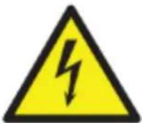
WARNING: TO REDUCE THE RISK OF ELECTRIC SHOCK, DO NOT REMOVE COVER. NO USER SERVICEABLE PARTS INSIDE.
REFER SERVICING TO QUALIFIED SERVICE PERSONNEL.
The exclamation point within an equilateral triangle is intended to alert the user to the presence of important operating and maintenance (servicing) instructions in the literature accompanying the device.
The lightning flash with arrowhead symbol within an equilateral triangle is intended to alert the user to the presence of uninsulated “dangerous voltage” within the device’s casing that may be of sufficient magnitude to constitute a risk of electric shock.
WARNING: TO PREVENT FIRE OR SHOCK HAZARD, DO NOT EXPOSE THIS UNIT TO RAIN OR MOISTURE.
CAUTION: TO PREVENT ELECTRIC SHOCK, MATCH WIDE BASE OF THE PLUG TO THE WIDE SLOT AND FULLY INSERT.
IMPORTANT SAFEGUARDS
This section provides precautions and safety measures to ensure you are using the DVR properly. Please read all information, and refer back to it if needed.
GENERAL PRECAUTIONS
- Follow all instructions and warnings in this manual.
- Unplug the device from the power source before cleaning it. Do not use liquid aerosol detergents; use a water-dampened cloth for cleaning.
- Do not use this device in humid or wet places.
- Keep enough space around the device for ventilation. Slots and openings on the device should not be blocked.
- It is highly recommended to connect the device to a surge protector to protect from damage caused by electrical surges. It is also recommended to connect the device (or surge protector) to an uninterruptible power supply (UPS), which has an internal battery to keep the device running in case of a power outage.
| CAUTION | Maintain electrical safety. Non battery powered equipment or accessories connected to this device should bear the UL listing mark or CSA certification mark on the accessory itself and should not be modified so as to cancel out the safety features. This will help avoid any potential hazard from electrical shock or fire. If in doubt, contact qualified service personnel. |
INSTALLATION PRECAUTIONS
- Read and Follow Instructions - Read all safety and operating instructions before setting up and using the device. Follow all operating instructions.
- Retain Instructions - Keep these safety and operating instructions for future reference.
- Heed Warnings - Follow all warnings on the device and in the operating instructions.
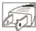
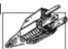
- Polarization - Polarized plugs and grounding plugs have different style blades. Be sure you are plugging the correct plug into the appropriate outlet. The wide blade or the third prong is provided for your safety. If the provided plug does not fit into your outlet, consult an electrician to replace the outlet.
- A polarized plug has two blades with one wider than the other.
- A grounding plug has two blades and a third grounding prong.
-
Power Sources - This device should be operated only from the type of power source indicated on the marking label. If you are not sure of the type of power supplied to your location, consult your local power company.
-
Overloading - Do not overload wall outlets or extension cords as this increases the risk of fire or electric shock. Overloaded AC outlets, extension cords, frayed power cords, damaged or cracked wire insulation, and broken plugs are dangerous. They may result in a shock or fire hazard. Periodically examine the cord, and, if its appearance indicates damage or deteriorated insulation, have it replaced.
- Power-Cord Protection - Route power supply cords so that they are not likely to be walked on or pinched by items placed on or against them. Pay particular attention to cords at plugs and the point where they exit from the device.
- Surge Protectors - It is highly recommended that the device be connected to a surge protector. Doing so will protect the device from damage caused by power surges. Surge protectors should bear the UL listing mark or CSA certification mark.
- Uninterruptible Power Supplies (UPS) - Because this device is designed for continuous, 24/7 operation, it is recommended that you connect it to an uninterruptible power supply. An uninterruptible power supply has an internal battery that will keep it running in the event of a power outage. Uninterruptible power supplies should bear the UL listing mark or CSA certification mark.
- Ventilation - Slots and openings in the case provide ventilation for reliable device operation and to protect it from overheating. These openings must not be blocked or covered. The openings should never be blocked by placing the device on a bed, sofa, rug, or other similar surface. Do not place it in a built-in installation such as a bookcase or rack unless proper ventilation is provided and all of these instructions and cautions have been followed.
- Attachments - Only use Uniden or Uniden recommended attachments.
- Water and Moisture - Do not use this device near water - for example, near a bath tub, wash bowl, kitchen sink, or laundry tub, in a wet basement, near a swimming pool, etc.
- Heat - The device should be situated away from heat sources such as radiators, heat registers, stoves, or other devices (including amplifiers) that produce heat.
- Placement - Ensure that any cart, stand, tripod, or table holding the device is stable; otherwise, the device may fall, causing serious damage to the device. Use this device only with a cart, stand, tripod, bracket, or table recommended by the manufacturer or sold with the device. Any mounting of the device should follow the manufacturer's instructions and use a mounting accessory recommended by the manufacturer.
- Camera Extension Cables - Check the rating of your extension cable(s) to verify compliance with your local authority regulations prior to installation.
- Mounting - The cameras provided with this system should be mounted only as instructed in this guide or the instructions that came with your cameras, using the provided mounting hardware.
- Camera Installation - Cameras are not intended for submersion in water. Not all cameras can be installed outdoors. Check your camera environmental rating to confirm if they can be installed outdoors. When installing cameras outdoors, place them in a sheltered area.
SERVICE
-
Servicing - Do not attempt to service this device yourself, as opening or removing covers voids the warranty and may expose you to dangerous voltage or other hazards. Visit our website at www.uniden.com for servicing assistance.
-
Conditions Requiring Service - Unplug this device from the wall outlet and contact Uniden customer care specialists under the following conditions:
-
When the power supply cord or plug is damaged.
- If liquid has been spilled or objects have fallen into the device.
- If the device has been exposed to rain or water.
- If the device has been dropped or the case has been damaged.
- If the device does not operate normally by following the operating instructions. Adjust only those controls that are covered by the operating instructions. Improper adjustment of other controls may void the warranty, resulting in costly repairs or replacement.
-
When the device exhibits a distinct change in performance.
-
Replacement Parts - Use only replacement parts verified by Uniden customer care specialists to have the same safety characteristics as the original parts. Use Uniden-specified replacement parts to prevent fire, electric shock, or other hazards.
MAINTENANCE
- Cleaning - Unplug the device from the wall outlet before cleaning. Do not use liq uid or aerosol cleaners. Use a damp cloth for cleaning.
- Object and Liquid Entry - Never push objects of any kind into this device through openings as they may touch dangerous voltage points or "short-out" parts that could cause a fire or electric shock. Never spill liquid of any kind on the device.
- Lightning - For added protection during a lightning storm, or when it is left unattended and unused for long periods of time, unplug it from the wall outlet and disconnect cables and other cords. This will prevent damage due to lightning and power line surges.
CONTENTS
Customer Care ....ii
IMPORTANT SAFEGUARDS....IV
GENERAL PRECAUTIONS....iv
INSTALLATION PRECAUTIONS....iv
SERVICE....vi
MAINTENANCE ...... vi
PACKAGE CONTENTS 1
RECEIVER PACKAGE 1
CAMERA PACKAGE 2
FEATURES....3
PRODUCT OVERVIEW....3
NVR RECEIVER FRONT PANEL 4
UNVR85X8 RECEIVER REAR PANEL 4
UNVR165X16 RECEIVER REAR PANEL 5
SET UP 6
RECEIVER CONNECTIONS....6
Connect the Cameras....6
Connect the Mouse....7
Connect the Ethernet Cable 7
Connect the Monitor 7
Connect the Power Adapter and Power ON the NVR 8
CONNECTING CAMERAS 8
Installing Cameras ....8
MOUSE CONTROL....11
MOUSE FEATURES ....11
LEFT BUTTON 11
RIGHT BUTTON 11
SCROLL WHEEL....11
BASIC OPERATION....12
START UP THE UNVR SYSTEM.... 12
On-Screen Display 12
Main Menu 13
SET THE DEVICE TIME 15
PTZ (Pan-Tilt-Zoom)....20
Capture....21
Alarm 21
File Manager....21
Setting. 22
Account. 35
Record 39
Display Setting 40
Image Setting 41
IP Channel Setting 41
IP Channel Setting - Manual 42
OTHER MAIN MENU OPTIONS 43
QUICK SETUP 43
POWER OFF.... 43
REBOOT 44
LOGOUT 44
DEVICE TIME 44
VOLUME 44
REMOTE ACCESS.... 45
FIRMWARE UPDATE 46
MAINTENANCE 47
RECYCLING AND DISPOSAL INFORMATION.... 47
COMPLIANCE AND WARRANTY 48
FCC COMPLIANCE 48
IC COMPLIANCE 48
ONE-YEAR LIMITED WARRANTY 48
PACKAGE CONTENTS
RECEIVER PACKAGE
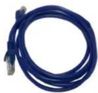
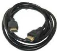
6 ft Ethernet Cable 6 ft HDMI Cable

natural_image
Exterior view of a black Uniden wireless router with ports and indicator lights (no readable text beyond branding)NVR Receiver
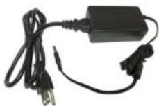
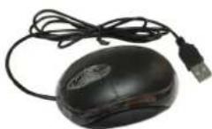
12V Power Supply USB Mouse
Receiver Package Contents
CAMERA PACKAGE
natural_image
White surveillance camera with attached black cable and USB port (no visible text or symbols)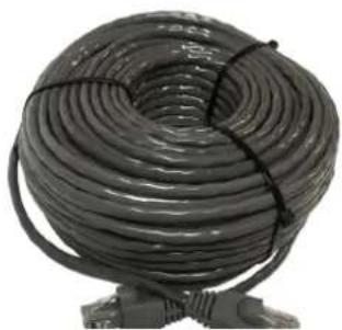
natural_image
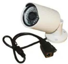
Coiled black cable with black straps, mounted on a stand (no text or symbols visible)Outdoor Cameras (4 or 8) 100ft. Cat5E Cable (4 or 8)
natural_image
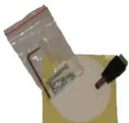
Close-up of a plastic bag and a small black tool on a yellow surface (no visible text or symbols)Not Shown:
Hex Wrench Quick Start Guide InstallerNet Insert
Camera Mounting Kit
Camera Package Components
FEATURES
PRODUCT OVERVIEW
The UNVR Receiver provides a high-performance security network using a standard H.264 video compressed format. The UNVR can be used as a stand alone device or online as a part of a video surveillance network. With its professional network video surveillance software, the UNVR supports:
• High definition 1080p recording.
• Real-time recording at 30fps per channel.
• 24/7 security-grade hard drive.
• Continuous, scheduled, and motion recording.
• H.264 video compression.
- HDMI cable included for simple connection to HD TVs.
- PTZ cameras supported, remotely controlled through a mobile App.
- Accurate time stamps with NTP & daylight savings time.
• Digital zoom in live view and playback.
- 2 video outputs (HDMI & VGA) to connect multiple monitor types.
- Instant USB backup of live video from selected camera.
- Upgradeable firmware.
• 3-Step remote view.
• Supports Internet Explorer, Safari, Chrome, and FireFox.
- Free Uniden ProHD iOS and Android compatible apps with live viewing, playback, video recording, and snapshot capability.
- Instant email alerts with attached snapshots.
NVR RECEIVER FRONT PANEL
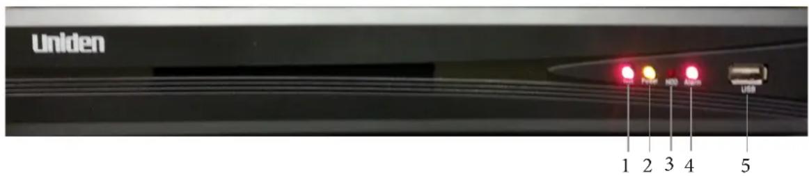
NVR Receiver Front Panel
| 1 Network connected |
| 2 Power connected |
| 3 Hard Disk Drive indicator |
| 4 Alarm indicator |
| 5 USB port |
UNVR85X8 RECEIVER REAR PANEL
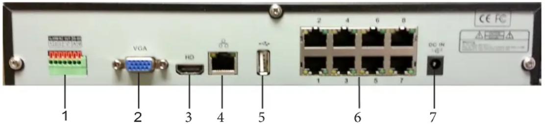
UNVR85x8 Receiver Rear Panel
| 1 RS485 and Alarm In/Out Connections: Connect external alarm devices. |
| 2 VGA: Connect a VGA monitor (not included) to view the system interface, and live or recorded playback. |
| 3 HDMI: Connect the included HDMI cable from this port to an HDMI monitor or TV (not included) to view the system interface, and live or recorded playback. |
| 4 WAN: Connect the included CAT5E Ethernet cable to your existing router or network for local and remote connectivity. |
| 5 USB port: Connect the included USB mouse. |
| 6 Camera Input: Connect the Uniden 1080P Wired HD cameras. |
| 7 DC IN: Connect the included AC power adapter. |
UNVR165X16 RECEIVER REAR PANEL
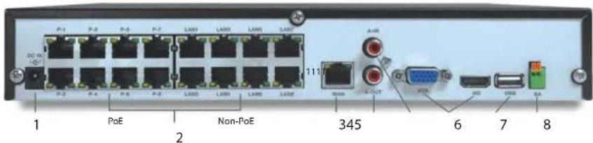
UNVR165x8 Receiver Rear Panel
| 1 DC IN: Connect the included AC power adapter. |
| 2 Camera Input: Connect PoE (Power over Ethernet) and Non-PoE cameras. Non-PoE cameras require a separate AC adapter for power. |
| 3 WAN: Connect the included CAT5E Ethernet cable to your existing router or network for local and remote connectivity. |
| 4 Audio Out |
| 5 Audio In |
| 6 VGA and HDMI: Connect a VGA monitor (not included) or the included HDMI cable from this port o an HDMI monitor or TV (not included) to view the system interface, and live or recorded playback. |
| 7 USB port: Connect the included USB mouse. |
| 9 RS-485 and Alarm IN/OUT Connections: Connect external alarm devices. |
SET UP
RECEIVER CONNECTIONS
Connect the Cameras
Connect the cameras to the video inputs on the NVR's rear panel. Insert the connector fully until you hear a click, indicating the plug is secure.
8-Channel UNVR
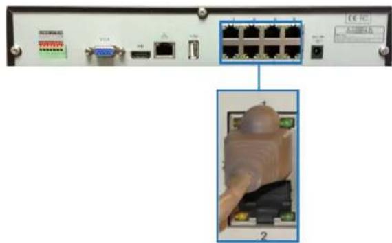
Connect to PoE Port
Note: Although the Uniden NVR system is compatible with other manufacturers' cameras, only the supplied Uniden bullet camera and the optional Uniden dome camera are plug and play. Refer to the manufacturers' camera owner's manuals for installation instructions. Before mounting the cameras in a permanent location, connect all cameras to ensure operation and video quality.
16-Channel UNVR
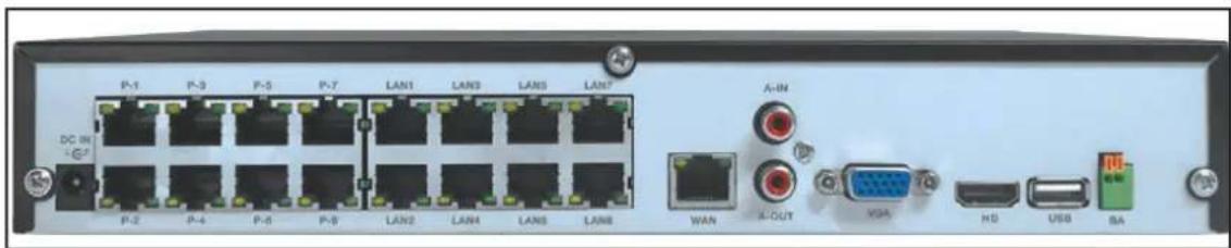
Connect Cameras to PoE Ports P1 - P8
Connect the Mouse
Connect the USB mouse to the USB port on the NVR's rear panel.
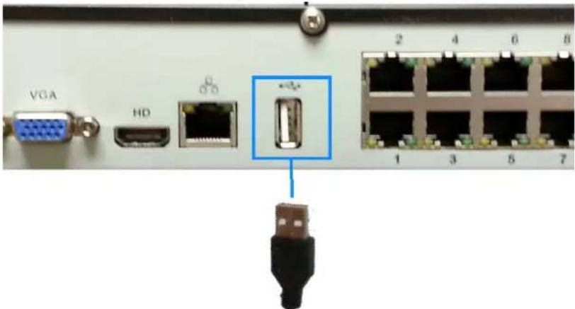
Connect the USB mouse
Connect the Ethernet Cable
- Connect the Ethernet cable to the LAN port on the NVR's rear panel.
- Connect the other end of the Ethernet cable to a router on your network.
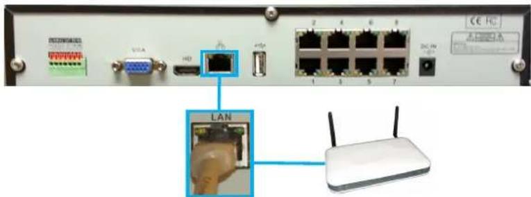
Connect the Ethernet cable
Connect the Monitor
Connect the HDMI cable from the HDMI port of the NVR's rear panel to the HDMI port on the TV or monitor.
OR
Connect a VGA cable (not included) from the VGA port on the NVR's rear panel to the VGA port on the TV or monitor.
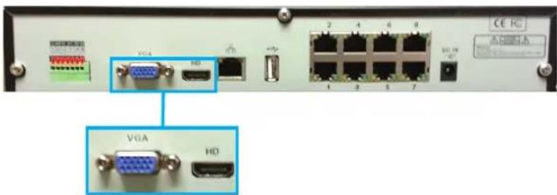
Connect the Monitor with HDMI or VGA
Connect the Power Adapter and Power ON the NVR
- Connect the included power adapter to the DC IN port on the NVR's rear panel. Then connect the power adapter to a wall socket or a surge protector.
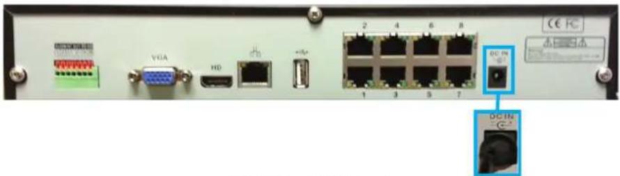
Connect Power
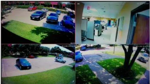
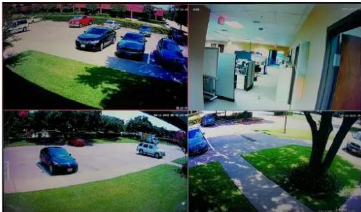
- The UNVR logo appears on the TV screen and a short beep sounds as the system performs a self check. After a few minutes a live view appears as shown from the camera(s) connected.
natural_image
Four-panel surveillance camera photo showing outdoor parking, indoor service hall, and parked cars (no visible text or symbols)UNVR Live Camera View
CONNECTING CAMERAS
Note: A professional installation option is available. See the InstallerNet insert.
Installing Cameras
| CAUTION | Each type of camera requires different installation techniques. For specific installation instructions check the documentation supplied with the camera. |
Installation Tips
- Test the cameras before permanent installation. Make a plan for camera wire routing and for camera angle.
- Mount the camera so the lens is away from direct and intense sunlight.
- Plan to route the wiring so it does not interfere with power lines or telephone lines.
- Ensure that the camera wiring is not exposed or easily cut.
- Mount the camera in an area that is visible, but out of reach.
- Avoid pointing the camera at a glass window to see outside. This may result in a bright white ring in the night vision image, as the light from the night vision LEDs may reflect off the glass.
- Adjust the camera angle so that it covers an area with high traffic.
- In "high-risk" locations, have multiple cameras point in the same area. This provides camera redundancy if a vandal attempts to damage the camera.
Installing the Cameras
Note: The following installation instructions refer to the cameras included with the UNVR package. If installing another manufacturer's camera, refer to installation instructions included with that camera.
-
Mount the camera(s) to the desired surface using the parts in the supplied mounting kit. Choose a firm mounting surface. If mounting in drywall, use the drywall anchors supplied in the kit.
-
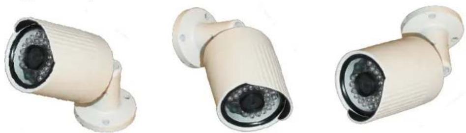
Adjust the camera stand to ensure that the camera has a satisfactory view of the area you would like to monitor. Stand configuration depends on the mounting surface you have chosen (see below for suggested stand configurations).
natural_image
Three identical security camera modules shown from different angles (no text or symbols visible)Table Mount Wall Mount Ceiling Mount
Camera Mounting Options
Note: Camera may not be exactly as shown.
Adjusting the Camera View Angle
The camera has several adjustment points to provide maximum flexibility when setting the view angle. To make the adjustments, use the hex key included with the Camera Mounting Kit.
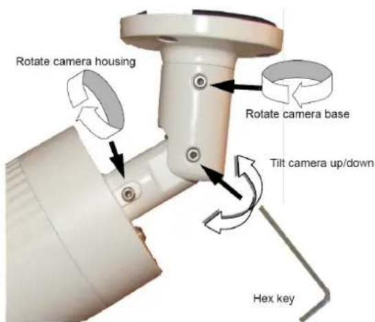
Camera View Angle Adjustments
Connecting Camera Cables
| CAUTION The | extension cable must be a single stretch of cable between the NVR and camera. You cannot connect multiple extension cables to each other. |
8-Channel NVR
- Connect one end of the included CAT5E cable to the camera.
- Route the cable and connect the other end to one of the Video IN ports on the NVR's rear panel.
16-Channel NVR
- Follow Steps 1 and 2 above.
- Connect each camera's power cable to an AC power outlet.
MOUSE CONTROL
MOUSE FEATURES
The mouse is the primary control device for the system.
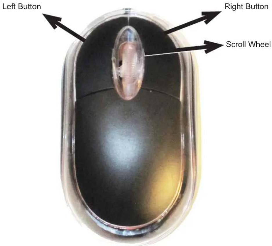
Mouse Control
LEFT BUTTON
• In live view, click to open the Navigation Bar. Right-click to close it.
- In live view while in a split-screen display mode, double-click an individual channel to view it in full-screen. Double-click again to return to the split-screen display mode.
- While navigating menus, click to open a menu option.
RIGHT BUTTON
• In live view, right-click anywhere on the screen to open the Main Menu.
- Within system menus, right-click to exit menus.
SCROLL WHEEL
- When viewing an image in live view, use the scroll wheel to zoom in or out.
BASIC OPERATION
-
Plug in the power supply. The power indicator lights up, the system emits a single beep, and the preview screen displays.
-
The UNVR's normal start-up mode is multi-screen.
natural_image
Four-panel surveillance camera photo showing cars parked in a lot, a gas station with charging equipment, and a parking lot with vehicles (no visible text or symbols)UNVR Multi-Screen
• The UNVR system displays live views of any cameras connected.
- The main camera is highlighted. Click on another screen to set it as the main camera.
- Local time and date are set automatically through the network connection.
On-Screen Display
The UNVR system shows the following for all live views.
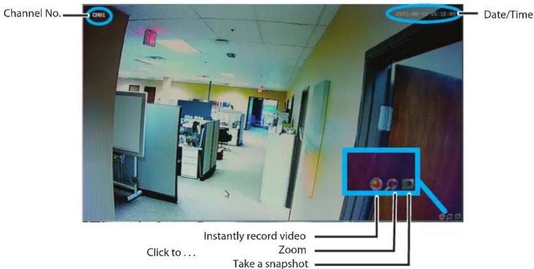
Screen Displays
Main Menu
The Main Menu allows access to the UNVR's key functions. Using the mouse, right click the screen during a live view to display the Main Menu.
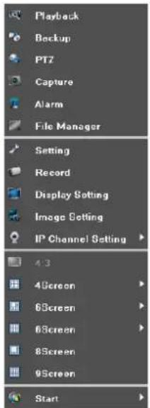
Main Menu
The following features are available without having to log in.
• 4:3 - Changes the live view screen aspect ratio from 16 X 9 to 4 X 3.
- The 4 Screen, 6 Screen, 8 Screen and 9 Screen menu items allow for displaying 4, 6, 8, or 9 live view screens at the same time. Click the desired screen configuration.
- When in Quad view (4 screen), Series 1 and 2 change from viewing Cameras 1 - 4 to viewing Cameras 5 - 8.
Working With Multiple Live View Screens
This is a typical view of the 8 Screen format.
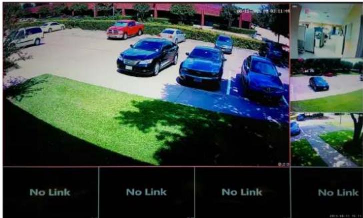
8-Screen Format
To display a channel view in the larger screen, drag and drop any channel live view into the larger screen.
During a live view with multiple screens displayed, double click any channel to view it in full screen.
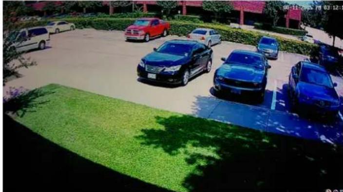
natural_image
Exterior view of a parking lot with multiple cars and green lawn, no visible text or signageFull Screen
Log into the System
You must log into the system to access all features of the UNVR.
- Hover the cursor over Start.
A sub menu displays:
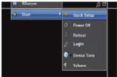
Access Login Screen
- Click Login.
The Login screen displays:
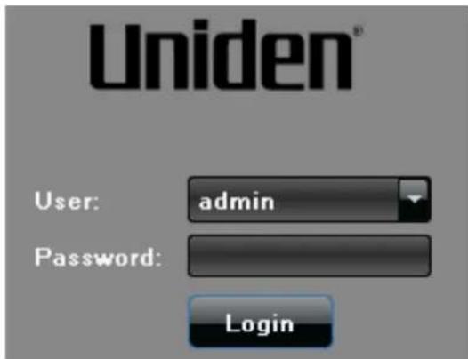
Login Screen
- Enter the default user name (admin), leave the password field blank, and click Login.
Change Password
Note: It is strongly recommended that you add a password to your system.
-
Right click the screen to display the Main Menu, then left click Start/Setting.
-
Click Account.

| User Name | Priority | IP combine | MAC combine |
| admin | Administrator | 00:00:00:00:00:00 | |
| default | Guest | 00:00:00:00:00:00 |
-
Click the admin field.
-
Click Modify User in the lower right corner. Use the on-screen keypad to enter and confirm a password. Click OK.
Modify User
SET THE DEVICE TIME
After logging in, access the Settings menu to set the UNVR system date and time.
- Use the mouse and right-click anywhere on the screen. The Main Menu screen displays.
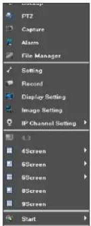
Main Menu Screen
- Click Setting. Setting Menu displays:
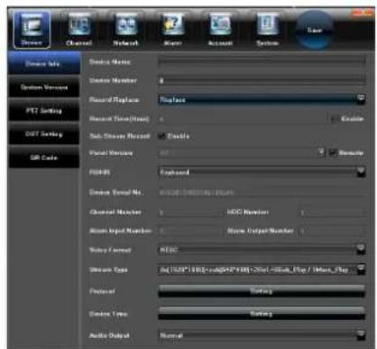
Setting Screen
- Scroll to near the bottom of the screen to Device Time and click Setting. The Device Time screen displays.
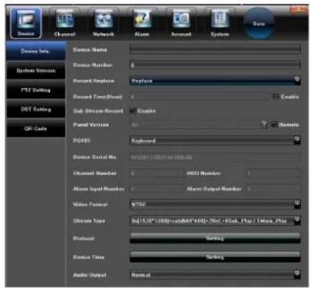
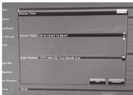
Accessing Device Time
- To the date and time for your location, click the field and then click the up or down arrows.Click OK when complete.
ADVANCED OPERATION
LOG INTO THE SYSTEM
To access the Advanced Settings in the Main Menu, log into the system.
- Hover the cursor over Start. A sub menu displays:
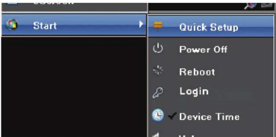
Access Login Screen
- Click Login. The Login screen displays:
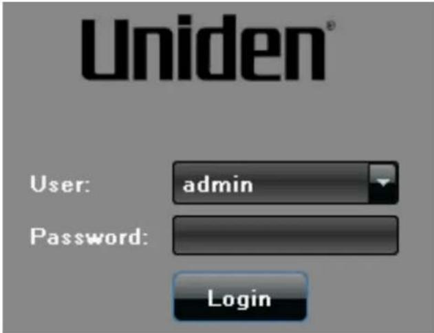
Login Screen
- Enter "admin" as the default user name and click Login.
Note: Change the user name and password to something easily remembered, and be sure to keep a record of the user name and password.
ADVANCED SETTINGS IN MAIN MENU
Right-click to access Main Menu
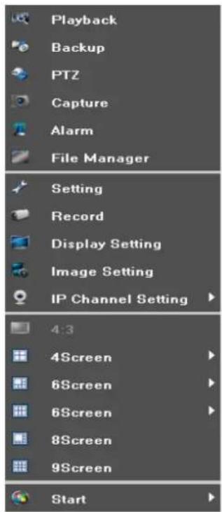
| Playback - Play video files stored on the hard disk |
| Backup - Backup video and capture files to an external storage device |
| PTZ - Set controls for a camera designed to Pan-Tilt-Zoom |
| Capture - Saves a photo of the image displayed on the screen |
| ALARM - Set alarms for motion detection, video loss, tampering, and other functions |
| File Manager - Organizes saved video and captured files. |
| Setting - Configure Device, Channel, Network, Alarm, and System parameters |
| Record - Set up recording for individual or all channels. |
| Display Setting - Set parameters for Text Language, Auto Logout, Image Display, Image Resolution, Camera Display Sequence |
| Image Setting - Set brightness, contrast, saturation, and hue for individual channels |
| IP Channel Setting - Configure network for the system |
Playback
The Playback screen replays recorded video from each individual channel.
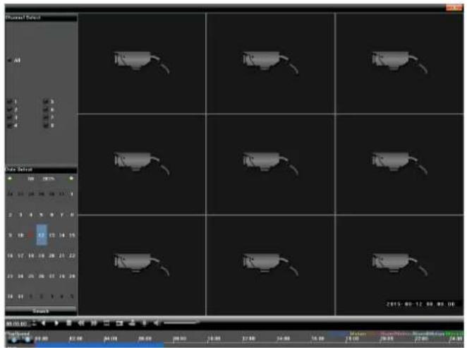
Playback Menu
- Pause: Pause the current playback.
- Stop: Stop the current playback.
-
Slow: Slow down the playback speed (1/2, 1/4, 1/8, 1/16 times available).
-
Fast: Speed up the playback process(2, 4,8,16 times available).
- Snapshot: Take a screen capture of any playback channel.
• Frame play: Play recording one frame at a time. - Backup: Make a backup video for any channel.
• Full screen: Video image playback on full screen.
• Volume: Adjust the volume of playback audio. - Double-click channel bar or click "Play" button to play the video.
- Double-click any single channel screen to get full screen display.
Backup
Store the backup video files from the hard disk to an external storage device such as a USB drive.
- Access the Backup screen.
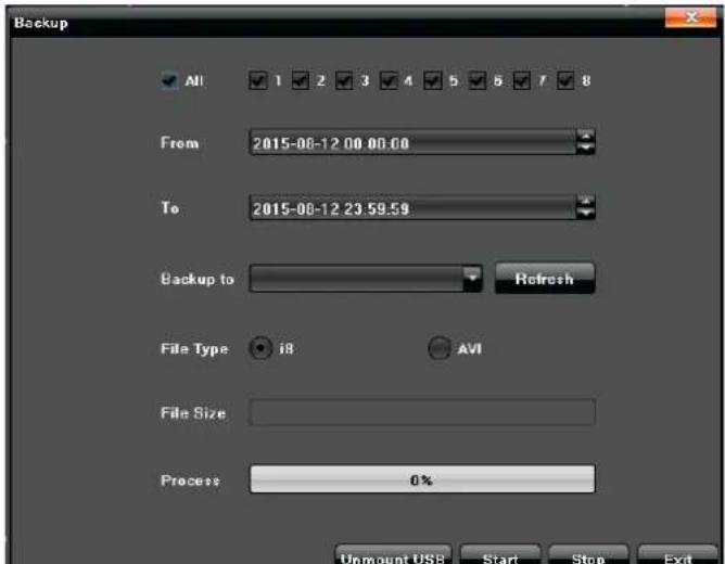
Backup Menu
- Insert a USB drive in the USB port on the NVR's front panel.
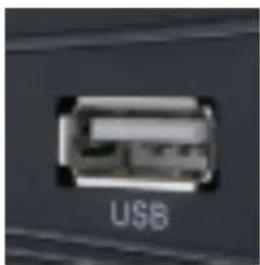
USB Port
- Click Refresh. The name of the USB backup device displays in the Back to field.
- Select a single channel or all channels for backup.
- Use the From and To fields to select a start and stop time for the backup.
- Click Start to begin the backup. The backup proceeds automatically. Click Stop to stop the backup at any time.
PTZ (Pan-Tilt-Zoom)
Note: This function requires a camera with PTZ capability (not included).
Set the controls for a camera equipped with Pan-Tilt-Zoom capability. Refer to the PTZ camera manufacturer's instructions for details on setting the camera's parameters.
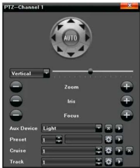
PTZ Camera Parameters Menu
Presets
The UNVR system can move a PTZ camera to a specific angle/point of view and then save that setting as a "preset" (preset 1, preset 2, etc).
- Use the PTZ directional buttons to rotate the camera to an appropriate angle.
-
Select a preset number in the drop-down list, and click
-
To recall a preset, select the desired preset in the drop-down list, then click

Cruise
"Cruise" refers to the camera's rotation speed.
-
On the "Cruise" interface, set preset, residence time (amount of time camera pauses at preset points), and cruise speed; click Add to confirm the settings. Click Delete to clear the preset.
-
To recall a cruise setting, select the desired cruise number in the drop-down list, then click
Track
This feature allows a PTZ camera to automatically detect, follow, and record video of moving persons or objects.
-
Select a track number in the drop-down list.
-
Click Track Start to set the PTZ camera operation, then click Track Stop to set the track in memory.
- To recall a track setting, select the track number in the drop down list and click

Capture
Capture allows you to take snapshots from live view.
- Right click the screen to display the Main Menu.
- Select Capture, then click the icon in the lower right corner of the desired live view screen.
- Click File Manager in the Main Menu.
- In the File Manager screen, click Refresh to verify that the snapshot just taken is listed.
- Double click the file name in the left portion of the screen to display the snapshot.
File Manager Screen
Alarm
The UNVR system keeps a record of any alarms received. Use the alarm parameters to tailor the alarms for different situations:
- Motion detection
- Video loss
- Tampering
To see a list of alarms received, right click the screen to display the Main Menu, then click Alarm.
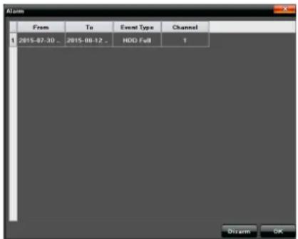
Alarms List
File Manager
File manager lists all video and capture files stored on the hard disk drive as well as any video or capture files stored on an attached external storage device such as a USB drive.
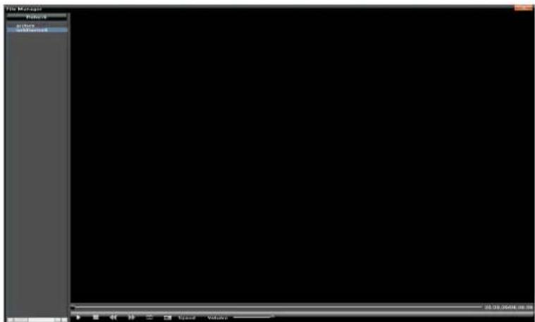
File Manager Screen
- In the File Manager screen, click Refresh to ensure the latest files display.
- Double click the file name in the left portion of the screen to display the captured image or file.
Setting
Main Menu - Setting
The Setting screen specifies parameters for several major functions in the UNVR system.
• Device (or Cameras)
- Channel
- Network
- Alarm
- Account
- System
Device
![Device Info. System Version PTZ Setting DST Setting QR Code Device Name Device Number 0 Record Replace Replace Record Time(Hour) 0 Enable Sub Stream Record Enable Panel Version 02 Remote R8405 Keyboard Device Serial No 0153012312214b188c46 Channel Number 8 HDD Number 1 Alarm Input Number 2 Alarm Output Number 1 Video Format NTSC Stream Type 0x[1920*1000] +sub[640*480] +2Ref. +8Sub_Play / 1Main_Play](/content/2026/06/1199234/images/531dc69941a7774c0239e412e3690c467e6869f3b00ceea7ec2b16a842c65c3c.jpg)
Setting Screen
Note: Set the correct date and time to ensure correct time stamping of recorded video.
Device Info
Set parameters or get information for the following:
• Device Name - Specify a name for the NVR.
• Device Number - Assign a number to the device.
- Record Replace - Enable record overwrite.
- Record Time (Hour) - Set the time for a recording.
- Sub Stream Record - Enable recording of both high and low resolution video.
- Panel Version - NA
• RS485 - Choose between keyboard, PTZ, or 485 PelcoD.
• Device Serial No. - Shows the serial number assigned to the NVR.
• Channel Number - Device channel capacity (8 or 16).
- HDD Number - The number assigned to the hard disk drive.
- Alarm Input Number - Number slot where the input from an alarm device connects to the NVR rear panel.
- Alarm Output Number - Number lot where the output for an alarm device connects to the NVR rear panel.
• Video Format - Choose between NTSC or PAL.
- Stream Type - Choose the resolution of the video stream.
- Protocol - Choose between 18, 18S, 18S Plug and Play, Onvif.
• Device Time - Set the NVR time and date.
• Audio Output - Choose between Normal or HDMI.
System Version
This tab shows specific system information.
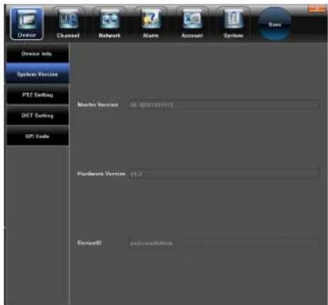
System Version Screen
• Master Version - Software version assigned to the NVR.
- Hardware Version - The hardware version of the NVR.
• Device ID - Specific ID number assigned to the NVR
PTZ Setting
Set parameters for a Pan-Tilt-Zoom (PTZ) camera.
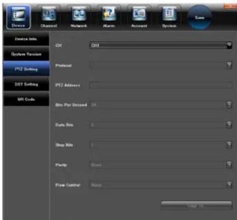
PTZ Setting Screen
- CH - The channel number where a PTZ camera connects Obtain the following information from the PTZ camera:
- Protocol
- Data Bits
- PTZ Address
- Bits per Second
- Flow Control
- Stop Bits
- Parity
DST Setting
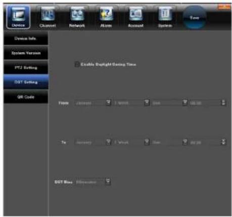
This screen sets Daylight Savings Time for the UNVR system.
- Click the Enable Daylight Saving Time box to activate the DST settings.
- Set Daylight Saving time to begin on the first Sunday in March and to end on the first Sunday in November.
This screen shows a Quick Response (QR) code that contains the Device ID generated by the NVR.
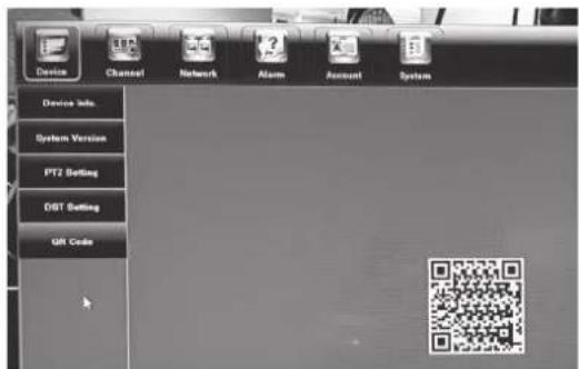
QR Code Screen
Channel
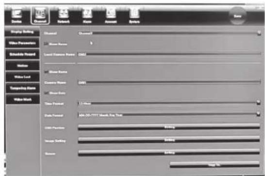
Channel Screen
The term “Channel” refers to each monitoring camera attached to the UNVR system. The Channel screen allows for setting parameters to control several features for each channel.
Display Setting
Sets parameters for each camera's screen display.
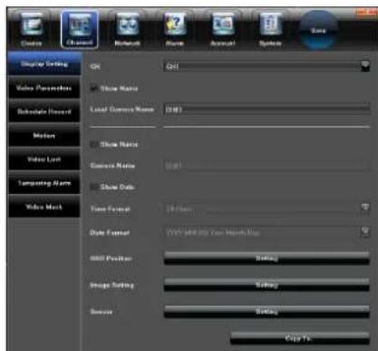
Display Setting Screen
- CH - Choose the channel where the camera is connected.
• Show Name - Choose to show or hide the Local Camera Name. - Local Camera Name - Assign a name to specified camera.
• Show Date - Show or hide the current timed and date for the selected camera.
• Time Format - Choose 24-hour or 12-hour time display. - OSD Position - Sets the place on the screen where the camera video displays.
- Image Setting - Adjust the brightness, contrast, saturation and hue of the camera image.
- Sensor - Sets specifics for the camera sensor such as Day-Night IR settings, Exposure and Iris.
- Copy To - Allows copying all the display settings to other camera channels.
Video Parameters
This screen modifies video parameters for each camera.
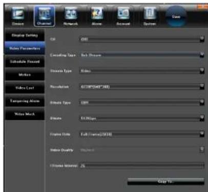
Video Parameters Screen
- Channel - Select the channel number to change parameters for each channel.
- Encoding Type - Choose from Main stream/ Sub stream/ Main stream (Event).
- Stream type - Video or Audio/Video optional.
Note: The included cameras do not support audio.
- Resolution - Settings for IPC supported resolution.
- Bit rate Type - CBR/VBR optional.
- Bit rate - Select the appropriate bit rate.
- Frame Rate - Choose frame rates from the drop-down list (Default = Full).
Note: Higher resolution, bit rate, and frame rate increase the size of recorded video files.
• Video quality - Choose the video quality level (Default = Highest).
- Frame interval - Set the video frame interval (Default = 25).
- Copy To - Allows copying the settings to other camera channels.
Schedule Record
Set recording parameters for each channel. Use the Copy To feature to transfer the settings to other channels.
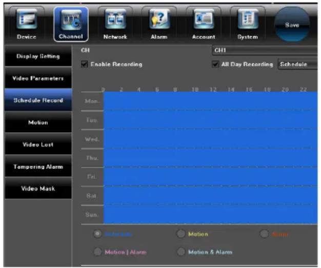
Schedule Recording Setting Screen
Set Scheduled Recording Times
You can set the system to record based on a schedule or you can manually turn recording on and off. By default, the system is set to an “always on” recording schedule.
Motion
Set parameters on each channel for detecting motion. Use the Copy To feature to transfer the settings to other channels.
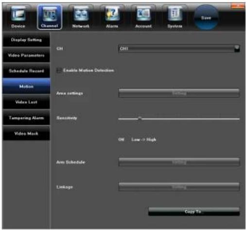
Motion Detection Setting Screen
Video Lost
Set up an alarm notification in case a camera loses video. Use the Copy To feature to transfer the settings to other channels.
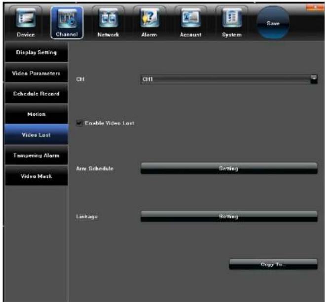
Video Lost Screen
Tampering Alarm
This screen sets parameters for triggering an alarm caused by tampering with a camera.
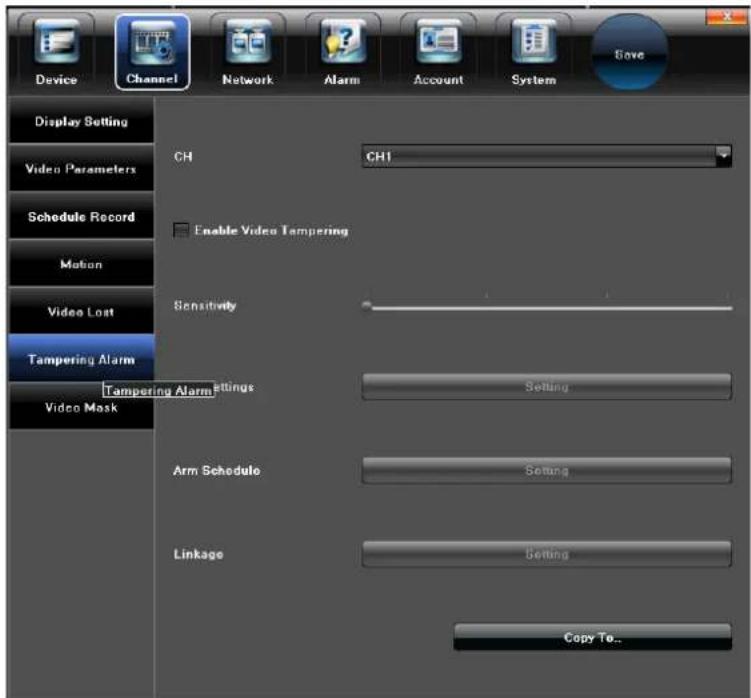
Tampering Alarm Screen
Video Mask
Use Video Mask to block off a portion of the camera's video.
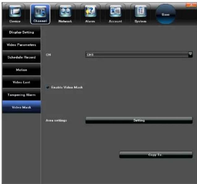
Video Mask Screen
Network
The Network Setting screen allows for setting parameters of a network interface.
Note: Except for Email settings, do not change the default network settings because changing the settings may result in loss of remote or local access.
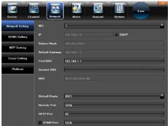
Network Screen
Network Settings
These settings do not require changes. The Uniden NVR system supports a P2P connection directly to the Uniden P2P Cloud Server for remote access to your system via an iPhone, iPad, and Android device using the Uniden ProHD app.
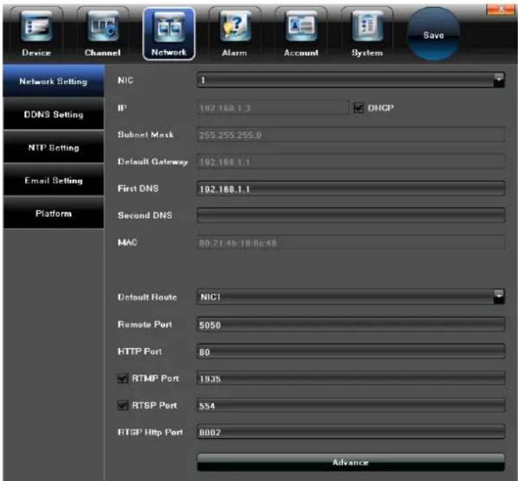
Network Settings Screen
DDNS Server Settings
The DDNS server allows for a connection to the Internet a PC with a fixed IP address.
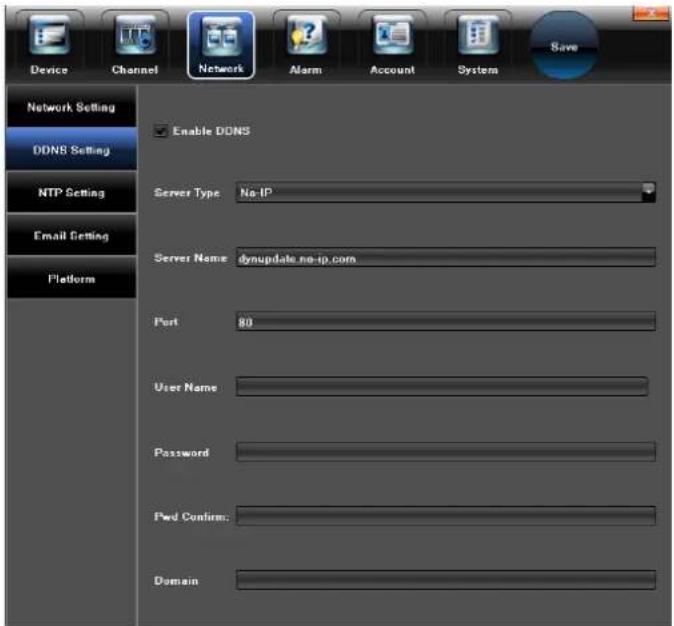
DDNS Settings Screen
NTP settings
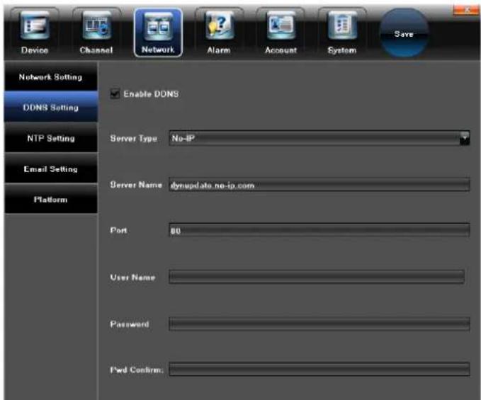
NTP Settings Screen
Email Setting
Set up parameters so the NVR can send status messages for motion detection or other events through email.
DDNS Setting Screen
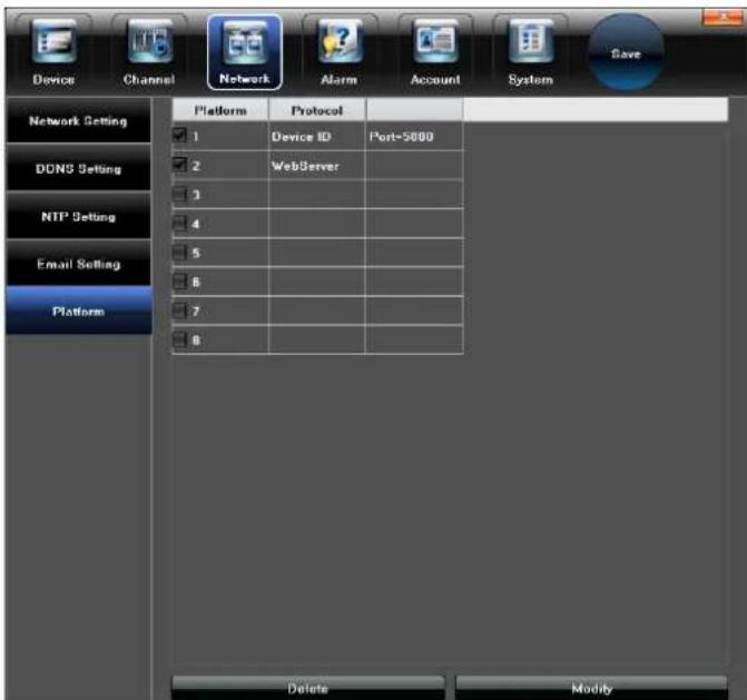
Management Platform
Set parameters management protocol such as iCloud or WebServer.
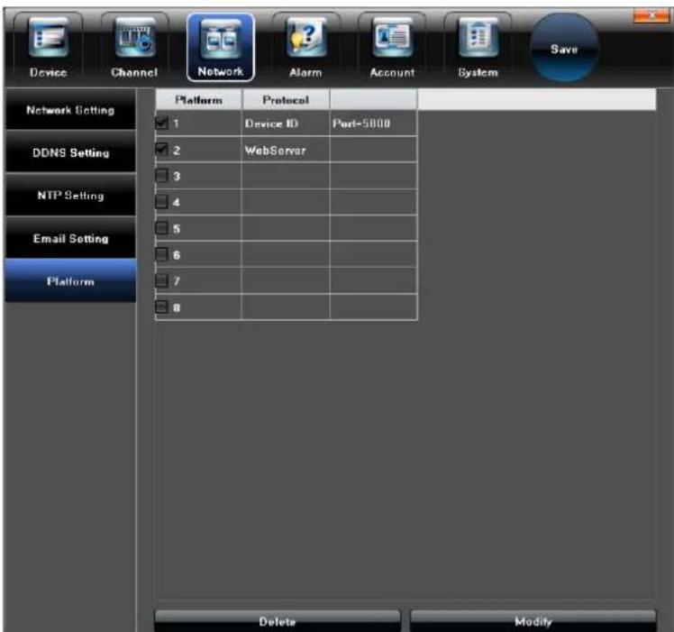
Management Platform Screen
Alarm
The Alarm screen allows configuring alarms for the UNVR system. The NVR alerts you by popping up live video and playing sound alerts for events such as motion detection, video loss, or hard disk drive problems.
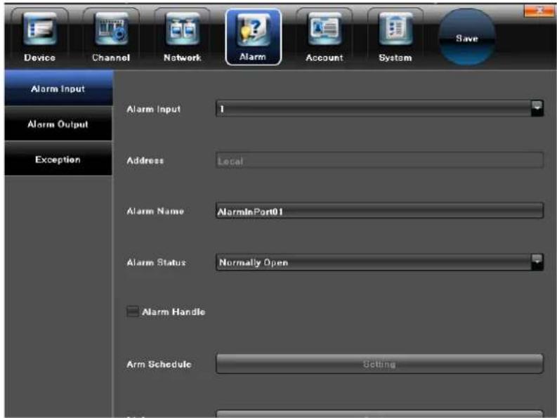
Alarm Screen
Alarm Input
Enables alarm processing, sets the alarm schedule, and selects the trigger mode.
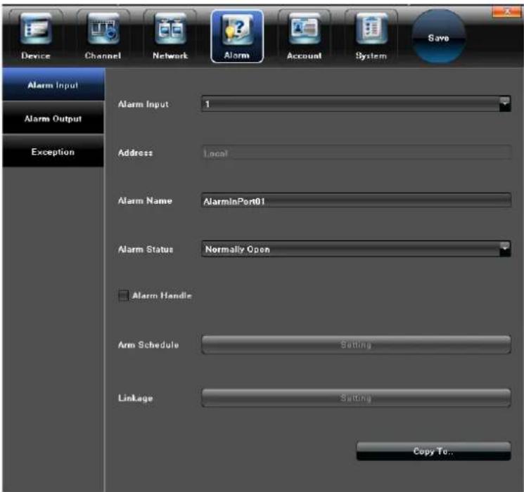
Alarm Input Screen
Alarm Output
Sets the alarm output delay and alarm schedule.
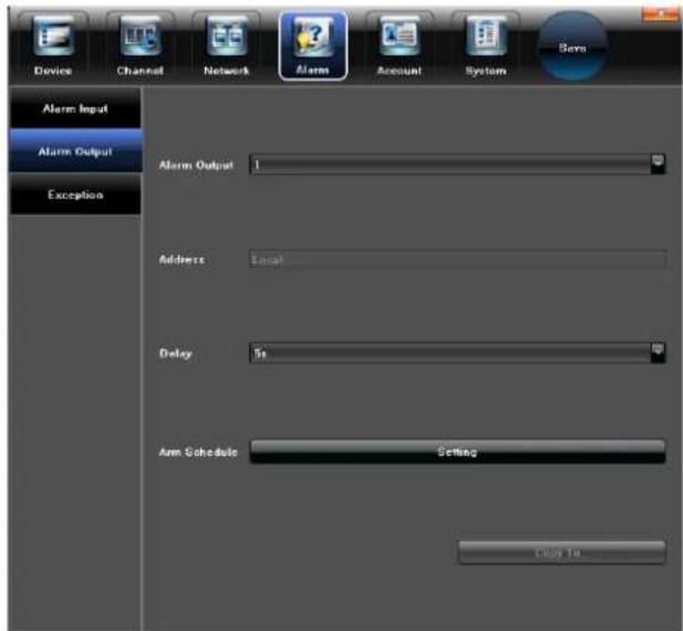
Alarm Output Screen
Exception
Sets parameters for alarm event types and alarm displays on the monitor. Allows you to choose an audio alarm type.
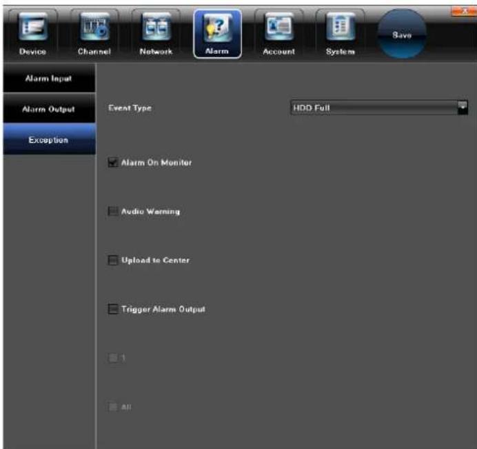
Alarm Exception Screen
Account
Enter details of the user account in this screen.
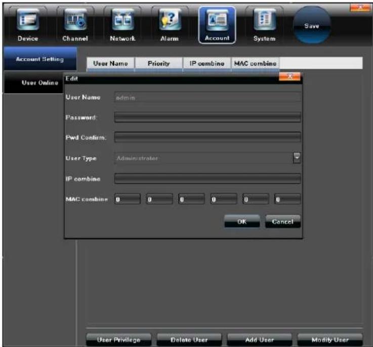
Account Screen
Account Setting
Enter user name, password, and specify user type.
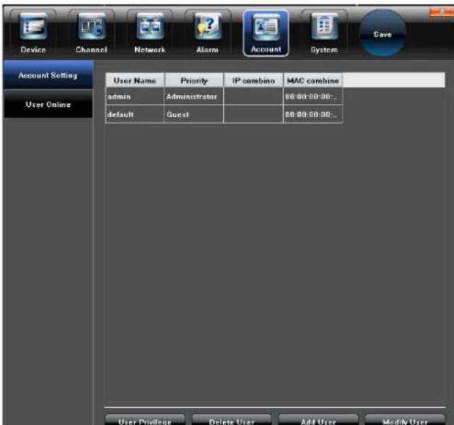
Account Setting Screen
User Online
Check the status of an online user's connection.
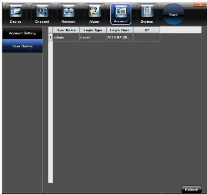
User Online Screen
System
The System screen allows for setting up system parameters as needed.
Device Log
Check the device logs according to the video type and date time.
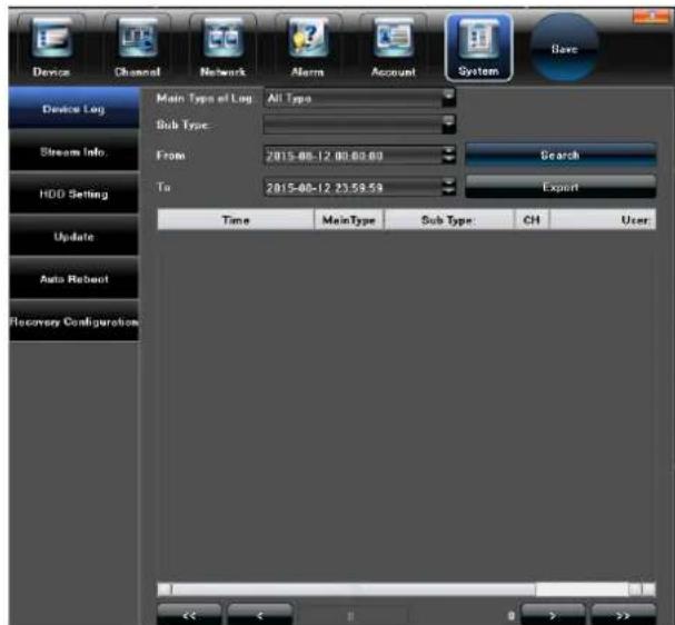
System Screen - Device Log
Stream Info.
View the band width of data streaming for each channel.
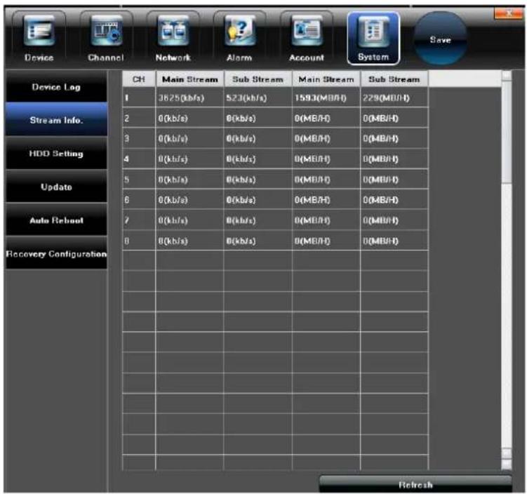
System Screen - Stream Info.
HDD Setting
Check the capacity and free space of the HDD (hard Disk Drive), and format the HDD if needed.
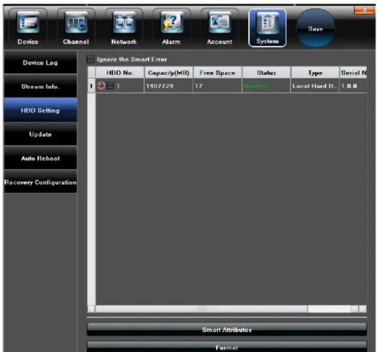
System Screen - HDD Setting
Update
Update the UNVR system hardware.
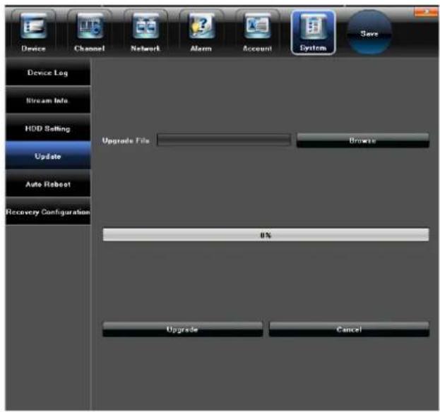
System Screen - Update System
Auto Reboot
Enable or disable the UNVR system for rebooting once, daily, or weekly.
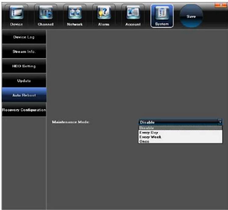
System Screen - Auto Reboot
Recovery Configuration
Export or import a recovery configuration file.
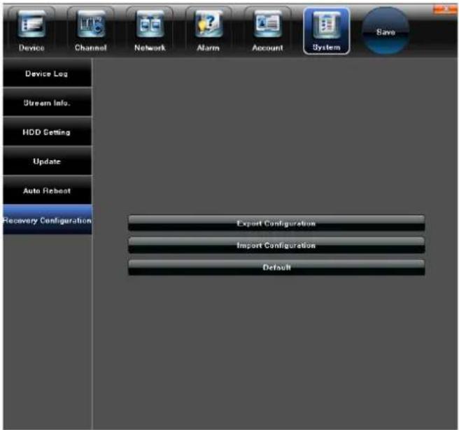
System Screen - Recovery Confirmation
Record
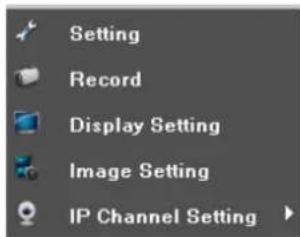
Main Menu - Record
The Record screen allows for setting the system to record based on a schedule or you can manually turn recording on or off for all channels or individual channels.
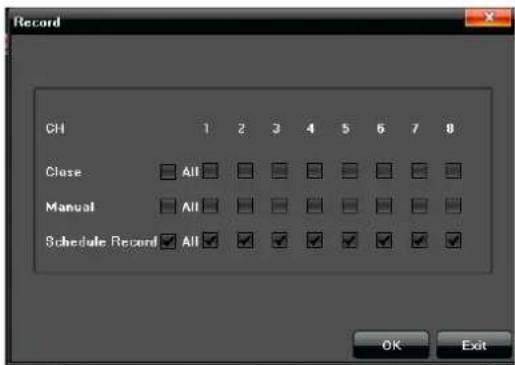
Record Screen
Display Setting
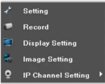
Main Menu - Display Setting
![Display Setting Language English AutoLayout 0 Minute Display Setting Resolution 1200x1024[60Hz] Enable SEQ Setting Rotation Interval 5 (s) OK Cancel](/content/2026/06/1199234/images/3974a2b648073946ed2eb11de4102bc7df2df037e0eb94c95084a19d3086c89e.jpg)
Display Setting Screen
Set up the following parameters in theDisplay screen:
- Language - Different kinds of languages for selection (English, French, Spanish, etc.).
- Auto Logout - It will logout automatically with no operation during the selected minutes.
- Display - Adjust the brightness/ contrast/ saturation/hue of the video screen display
- Resolution - Select a different resolution to match the resolution of the connected TV or monitor.
- Enable SEQ - Click the icon in front of "Enable SEQ" to include the channel in the image rotation
- Rotation Interval - Sets the rotation interval time (seconds).
Image Setting
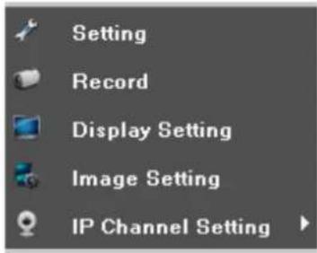
Main Menu - Image Setting
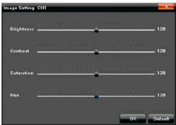
Image Setting Screen
Adjust the following items in the Image Setting screen:
- Brightness
- Contrast
- Saturation
- Hue
IP Channel Setting
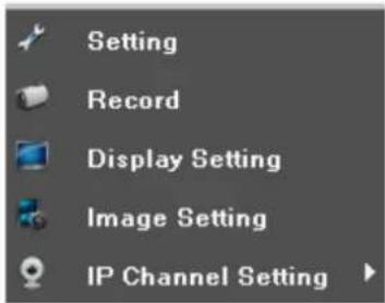
Main Menu - IP Channel Setting
IP Channel Setting - Manual
Note: The IP Channel Settings do not require changing. The system automatically identifies when cameras are attached and assigns the IP addresses.
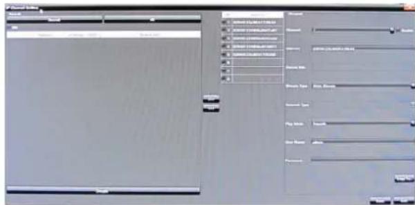
IP Channel Setting - Manual
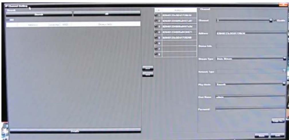
IP Channel Setting Screen
This IP Channel Setting screen allows setting up parameters for connecting the UNVR system to the Internet.
Choose Manual or Automatic to set up all channels or individual channels.
OTHER MAIN MENU OPTIONS
Hover the mouse over Start in the Main Menu and these options display:
- Quick Setup
- Power Off
- Reboot
- Logout
- Device Time
- Volume
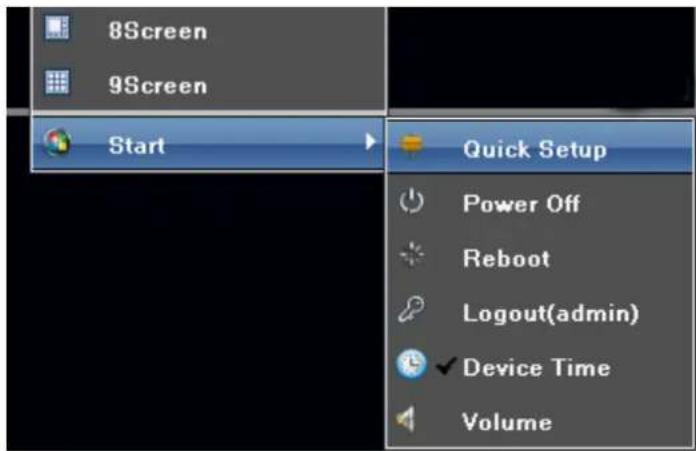
Main Menu Features Under Start
QUICK SETUP
Click Quick Setup to return to the initial system setup screens.
POWER OFF
- Click Power Off to shut down the UNVR system.
- Unplug the Power Adapter to fully remove power from the NVR.

Main Menu - Power Off
REBOOT
Click Reboot to reboot the UNVR system automatically.

Main Menu - Reboot
LOGOUT
Click Logout to exit the advanced feature items in the Main Menu.

Logout(admin)
Main Menu - Logout
DEVICE TIME
Click Device Time to set the UNVR system time.

Device Time
Main Menu - Device Time
VOLUME
Click Volume to change the volume of the SELECTED live screen.

Volume
Main Menu - Volume
Note: The camera on the channel showing the live view screen must be equipped with a microphone to pick up sounds around the camera.
REMOTE ACCESS
You can also remotely access your UNVR system through Uniden's ProHD app for iOS or Android devices. Go to the Apple App Store or Google Play to download the free Uniden ProHD app.
The app is designed to be self-explanatory. However, you can download the Uniden ProHD App manual from www.uniden.com if you need assistance.
FIRMWARE UPDATE
From time to time, Uniden may update its products' firmware to improve features, fix bugs, or otherwise improve the product. Uniden recommends checking for firmware updates periodically.
Note: Check for firmware updates if you have service issues; your firmware may be out of date.
- Go to Main Menu/Information/System Information to locate the current NVR firmware version.
- Go to http://unidensupport.com/Find-Your-Product/Downloads and look for the NVR. Check your DVR's firmware version against the latest firmware download available.
- If there is a firmware version that is later than the firmware version on your system, download it to your USB drive.
- Insert USB drive into USB port on front of NVR.
- Go into Settings/System Menu and select Update.
- Select Browse button and choose the new FW file on the USB drive.
- Select Upgrade button
- System will upgrade and then reboot.
In some cases, there may be an additional file that accompanies the FW upgrade. This is a configuration file. After the FW upgrade is complete, repeat the process selecting the configuration file.
After all of this is complete and the NVR reboots, return to the System tab and select Recovery Configuration. Select the Default button and check the All box and then OK. Once again the NVR will reboot and the upgrade is complete.
MAINTENANCE
Use a damp cloth to wipe down the outside casings of the NVR equipment. Do not use harsh abrasives or chemicals as they could get inside the casings and damage internal components.
Check plugs and cords periodically for wear.
RECYCLING AND DISPOSAL INFORMATION
- Do not dispose of electronic devices or any of their components (especially batteries and LCD displays) in your municipal trash collection.
- Consult your local waste management authority or a recycling organization like Earth911.com to find an electronics recycling facility in your area.
COMPLIANCE AND WARRANTY
FCC COMPLIANCE
FCC Compliance Statement: This device complies with Part 15 of the FCC rules. Operation is subjected to the following two conditions: (1) this device may not cause harmful interference, and (2) this device must accept any interference received, including interference that may cause undesired operation.
This device complies with Industry Canada license-exempt RSS standard(s). Operation is subject to the following two conditions: (1) this device may not cause interference, and (2) this device must accept any interference, including interference that may cause undesired operation of the device.
Changes or modifications not expressly approved by the party responsible for compliance could void your authority to operate the equipment.
Important: SAVE YOUR RECEIPT! Evidence of original purchase is required for warranty service.
WARRANTOR: Uniden America Corporation (“Uniden”) ELEMENTS OF WARRANTY: Uniden warrants, for one year, to the original retail owner, this Uniden Product to be free from defects in materials & craftsmanship with only the limitations or exclusions set out below.
WARRANTY DURATION: This warranty to the original user shall terminate & be of no further effect 12 months after the date of original retail sale. The warranty is invalid if the Product is (A) damaged or not maintained as reasonable or necessary, (B) modified, altered, or used as part of any conversion kits, subassemblies, or any configurations not sold by Uniden, (C) improperly installed, (D) serviced or repaired by someone other than an authorized Uniden service center for a defect or malfunction covered by this warranty, (E) used in any conjunction with equipment or parts or as part of any system not manufactured by Uniden, or (F) installed or programmed by anyone other than as detailed by the owner's manual for this product.
STATEMENT OF REMEDY: In the event that the product does not conform to this warranty at any time while this warranty is in effect, warrantor will either, at its option, repair or replace the defective unit & return it to you without charge for parts, service, or any other cost (except shipping & handling) incurred by warrantor or its representatives in connection with the
performance of this warranty. Warrantor, at its option, may replace the unit with a new or refurbished unit.
THE LIMITED WARRANTY SET FORTH ABOVE IS THE SOLE & ENTIRE WARRANTY PERTAINING TO THE PRODUCT & IS IN LIEU OF & EXCLUDES ALL OTHER WARRANTIES OF ANY NATURE WHATSOEVER, WHETHER EXPRESS, IMPLIED OR ARISING BY OPERATION OF LAW, INCLUDING, BUT NOT LIMITED TO ANY IMPLIED WARRANTIES OF MERCHANTABILITY OR FITNESS FOR A PARTICULAR PURPOSE. THIS WARRANTY DOES NOT COVER OR PROVIDE FOR THE REIMBURSEMENT OR PAYMENT OF INCIDENTAL OR CONSEQUENTIAL DAMAGES. Some states do not allow this exclusion or limitation of incidental or consequential damages so the above limitation or exclusion may not apply to you.
LEGAL REMEDIES: This warranty gives you specific legal rights, & you may also have other rights which vary from state to state. This warranty is void outside the United States of America & Canada.
PROCEDURE FOR OBTAINING PERFORMANCE OF WARRANTY: If, after following the instructions in the owner's manual you are certain that the Product is defective, pack the Product carefully (preferably in its original packaging). The Product should include all parts & accessories originally packaged with the Product. Include evidence of original purchase & a note describing the defect that has caused you to return it. The Product should be shipped freight prepaid, by traceable means, to warrantor at:
Uniden America Service
C/O Saddle Creek
743 Henrietta Creek Rd., Suite 100
Roanoke, TX 76262
- CUSTOMER CARE
- Important Safeguards
- WARNING
- GENERAL PRECAUTIONS
- INSTALLATION PRECAUTIONS
- SERVICE
- MAINTENANCE
- CONTENTS
- IMPORTANT SAFEGUARDS....IV
- PACKAGE CONTENTS 1
- FEATURES....3
- SET UP 6
- MOUSE CONTROL....11
- BASIC OPERATION....12
- OTHER MAIN MENU OPTIONS 43
- REMOTE ACCESS.... 45
- FIRMWARE UPDATE 46
- MAINTENANCE 47
- COMPLIANCE AND WARRANTY 48
- PACKAGE CONTENTS
- RECEIVER PACKAGE
- ft Ethernet Cable 6 ft HDMI Cable
- 12V Power Supply USB Mouse
- CAMERA PACKAGE
- Outdoor Cameras (4 or 8) 100ft. Cat5E Cable (4 or 8)
- Camera Mounting Kit
- FEATURES
- PRODUCT OVERVIEW
- NVR RECEIVER FRONT PANEL
- UNVR85X8 RECEIVER REAR PANEL
- UNVR165X16 RECEIVER REAR PANEL
- SET UP
- RECEIVER CONNECTIONS
- Connect the Cameras
- 8-Channel UNVR
- 16-Channel UNVR
- Connect the Mouse
- Connect the Ethernet Cable
- Connect the Monitor
- OR
- Connect the Power Adapter and Power ON the NVR
- CONNECTING CAMERAS
- Installing Cameras
- Installation Tips
- Installing the Cameras
- Camera Mounting Options
- Adjusting the Camera View Angle
- Connecting Camera Cables
- 8-Channel NVR
- 16-Channel NVR
- MOUSE CONTROL
- MOUSE FEATURES
- LEFT BUTTON
- RIGHT BUTTON
- SCROLL WHEEL
- BASIC OPERATION
- UNVR Multi-Screen
- On-Screen Display
- Main Menu
- Working With Multiple Live View Screens
- Log into the System
- Change Password
- Modify User
- SET THE DEVICE TIME
- Setting Screen
- Accessing Device Time
- ADVANCED OPERATION
- ADVANCED SETTINGS IN MAIN MENU
- Playback
- Backup
- PTZ (Pan-Tilt-Zoom)
- Presets
- Cruise
- Track
- Capture
- File Manager Screen
- Alarm
- File Manager
- Setting
- Main Menu - Setting
- Device
- Device Info
- System Version
- System Version Screen
- PTZ Setting
- PTZ Setting Screen
- DST Setting
- Channel
- Display Setting
- Display Setting Screen
- Video Parameters
- Schedule Record
- Set Scheduled Recording Times
- Motion
- Video Lost
- Tampering Alarm
- Tampering Alarm Screen
- Video Mask
- Network
- Network Settings
- DDNS Server Settings
- Email Setting
- Management Platform
- Alarm Input
- Alarm Output
- Exception
- Account
- Account Setting
- User Online
- System
- Device Log
- Stream Info.
- HDD Setting
- Update
- Auto Reboot
- Recovery Configuration
- Record
- Image Setting
- IP Channel Setting
- IP Channel Setting - Manual
- OTHER MAIN MENU OPTIONS
- QUICK SETUP
- POWER OFF
- REBOOT
- LOGOUT
- DEVICE TIME
- VOLUME
- REMOTE ACCESS
- FIRMWARE UPDATE
- RECYCLING AND DISPOSAL INFORMATION
- COMPLIANCE AND WARRANTY
- FCC COMPLIANCE
Brand : UNIDEN
Model : UNVR85-8
Category : Security Camera