Elevated Skin - Camera Digital Watchdog - Free user manual and instructions
Find the device manual for free Elevated Skin Digital Watchdog in PDF.


| Product Type | Elevated Skin Temperature System (Thermal + Visible Camera) |
| Brand | Digital Watchdog |
| Model Numbers | DW-ESTS (Kit), DW-ESTCAM (Camera only), DW-ESTBLKBD (Blackbody only) |
| Thermal Sensor | Microbolometer, uncooled FPA, 384 x 288 resolution, 17μm pixel pitch |
| Thermal Sensitivity | 50mK@f1.0, 30Hz, 300K |
| Visible Camera Sensor | 1/3" Progressive CMOS, 2.1 MP, 1920 x 1080 |
| Lens (Thermal) | 8.13mm f1.16, HFOV 47.4°, VFOV 35.1° |
| Lens (Visible) | 4.0mm, 70° HFOV |
| Recommended Distance | 6.5 to 16.4 ft (2 to 5 m); 10 ft recommended |
| Temperature Accuracy | ±0.36°F (±0.2°C) with Blackbody |
| Frame Rate | 30 Hz |
| Data Interface | Gigabit Ethernet (RJ45) for thermal data; USB 3.0 for visible video |
| Power Supply (Camera) | 12V DC |
| Power Supply (Blackbody) | 110/220 VAC to 12VDC adaptor, 36W (3A) |
| Dimensions (Camera) | 3.18 x 5.31 x 5.92 in (81 x 135 x 150.5 mm) |
| Weight (Camera) | 2.2 lbs (1000 g) |
| Dimensions (Blackbody) | 2.83 x 2.83 x 1.92 in (72 x 72 x 49 mm) |
| Weight (Blackbody) | 0.72 lbs (330 g) |
| Operating Temperature | 14°F to 104°F (-10°C to 40°C) |
| PC Requirements | Intel Core i5 (7th gen), 8 GB RAM, NVIDIA GTX 750, Windows 10 Pro 64-bit |
| Warranty | 2 years (parts and labor) |
| Intended Use | Non-contact skin temperature measurement for supplemental screening; not a medical device |
Frequently Asked Questions - Elevated Skin Digital Watchdog
User questions about Elevated Skin Digital Watchdog
0 question about this device. Answer the ones you know or ask your own.
Ask a new question about this device
Download the instructions for your Camera in PDF format for free! Find your manual Elevated Skin - Digital Watchdog and take your electronic device back in hand. On this page are published all the documents necessary for the use of your device. Elevated Skin by Digital Watchdog.
USER MANUAL Elevated Skin Digital Watchdog
Elevated Skin Temperature System

natural_image
Two white and red camera modules, one with 'DW' branding and the other a cylindrical lens (no text or symbols on main objects)| Part Numbers | Description |
| DW-ESTS | Camera + Blackbody Kit |
| DW-ESTCAM | Camera only |
| DW-ESTBLKBD | Blackbody only |
※ The picture might differ according to the specification and model.
※ Contents of this user manual are protected under copyrights and computer program laws.
Before operating the system, please read this User Manual and retain it for future reference.
※ Important Notice: DW E.S.T. is not designed by DW for the specific intention of human fever detection nor the diagnosis, mitigation, or prevention of disease or health conditions. Rather, the DW E.S.T. system is intended for the measurement of surface skin temperature as a supplemental method for thermal detection.
Rev: 09/20, Ver. 1.7
Contents
- What's in the Box....3
- Camera Connection .... 3
- Installation Diagram and Considerations....4
3.1. Installation Diagram....4
3.2. Installation Considerations....5 - Monitoring PC System Requirements 6
4.1. Hardware 6 - Installation Environment Before Installation....6
5.1. Check Windows 10 Version....6
5.2. Windows Update ....7
5.3. Display Setting....7
5.4. Power and Sleep 8 - Software Download and Installation....9
6.1. Download Software and Camera Network Configuration 9
6.2. Install the Software.... 11 - Program Installation....12
- Software Elements....15
8.1. Connection Information 15
8.2. Functions 15
8.3. Maximum Temperature Indication Window 19
8.4. Alarm Setting....20
8.5. History....21
8.6. Top Navigation Bar....22
8.7. Main Display....23
8.8. Blackbody Status 25
8.9. Status....25 - Run Program....25
- Specifications 27
- FAQs 29
11.1. Usability 29
11.2. Hardware Related 30
11.3. Compatibility 30
11.4. Compliance 31 - Warranty Information 32
- Limits and Exclusions 33
1. What's in the Box
Review and make sure the following is included in the box with your camera:
• DW-EST: Camera, Blackbody, 2x tripods, 2x DC12V power adapter, QSG.
• DW-ESTCAM: Camera, DC12V power, QSG.
• DW-ESTBLKB: Blackbody, DC12V power, QSG.
2. Camera Connection
Follow the connection diagram below to connect the camera to all external devices.
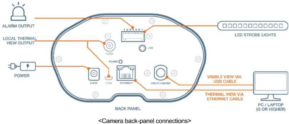
- AC/DC Adapter – Connect the power adapter to the camera. When the camera is connected to a proper power supply, the red light will turn on.
- Mini-true HD Output – Connect to a monitor.
- RJ45 (Ethernet) Output – The camera transmits raw data to the monitoring PC via an RJ45 connection. The LED lights up when data is transmitted and received.
- Alarm Output (Digital Output) – The camera can be integrated into an access control solution using two (2) digital outputs.
- Analogue Video Output – Secondary video output for local output during the installation.
- Color Camera Cable (Visible Camera) – The USB 3.0 cable connects the camera to the monitoring PC via a USB 3.0 port to get the visible camera's video output.
3. Installation Diagram and Considerations
3.1. Installation Diagram
The diagram below represents recommended installation settings.
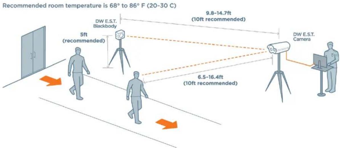
- Install the camera facing away from the entrance or windows.
- Place the camera 6.5\~16.4ft from the objects (10 feet recommended).
- Place the camera at a 20^ angle from the objects.
- Make sure people are walking into the camera's FoV rather than straight towards the camera.
- Only one person in the FoV at a time.
- Place the Blackbody across from the camera, positioned in the corner of the camera's FoV.
- For optimal readings, the Blackbody should be 9.8\~14.7ft from the camera (10 feet recommended).
- Recommended room temperature is 68^ to 86^ F ( 20^ to 30^ C).
- Set up a monitoring station next to the camera with a monitoring PC and personnel. See 'Camera Connection' for more information.
- Always follow elevated temperature readings with additional screening such as a medical thermometer and wellness questionnaire.
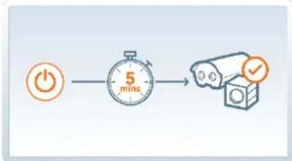
For DW-ESTS installations, where the camera is mounted with a Blackbody, allow up to 5 minutes for the camera to power up and calibrate properly.
flowchart
graph LR
    A["Power"] --> B["5 mins"]
    B --> C["Camera Icon"]
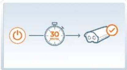
For DW-ESTCAM installations, where the camera is mounted without a Blackbody, allow up to 30 minutes for the camera to power up and calibrate properly.
flowchart
graph LR
    A["Power Button"] --> B["30-minute Timer"]
    B --> C["Checkmark Icon"]
3.2. Installation Considerations
When considering where to place your screening station, consider the following:
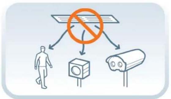
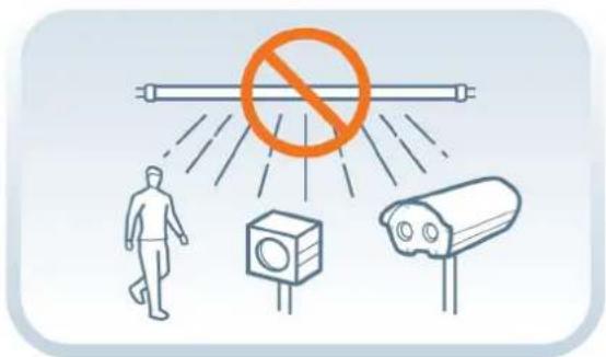
- Avoid placing your camera, Blackbody or people being screened directly under an AC vent or a strong fluorescent light. The air temperature and heat emitted from the light may impact the accuracy of the temperature readings.
flowchart
graph TD
    A["No Protection"] --> B["Surveillance Camera"]
    A --> C["Surveillance Camera"]
    B --> D[" pedestrian Walking"]
    C --> E["Surveillance Camera"]
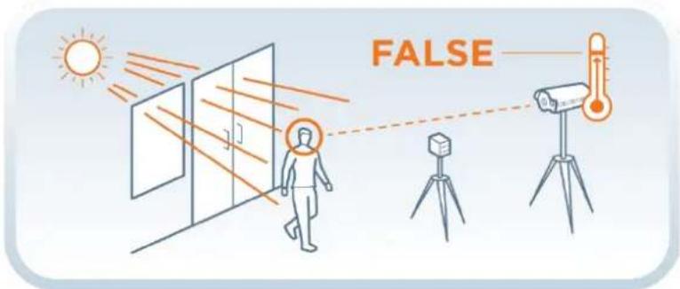
- Do not place the camera facing a window or large door. These may reflect strong light and heat from outdoors and have an impact on the accuracy of the temperature readings.
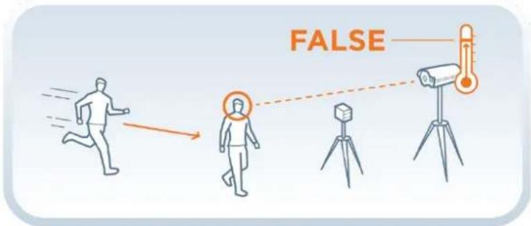
- Consider that any extensive physical activity performed before screening may impact the facial skin temperature captured by the camera.
4. Monitoring PC System Requirements
Below are the hardware recommendations for the PC used for the 'Elevated Skin Temperature System' monitoring software. These are the minimum required specifications for proper execution and usage of the software.
4.1. Hardware
• CPU: Intel Core i5 or higher (7th generation Intel Core or higher).
• RAM: 8GB or higher.
- HDD: A dedicated HDD is recommended for physical separation of HDD for program installation and HDD for data storage.
• VGA: NVIDIA GTX 750 or higher (maintain the latest driver).
- OS: Microsoft Windows® 10 Professional 32-bit/64-bit (version 1607 and later).
* Education edition causes installation problems, and not recommended
* Home edition may cause problems during the installation process.
5. Installation Environment Before Installation
5.1. Check Windows 10 Version
Use the shortcut keys of "Windows + R" to start the Launch window, and type "winver" and press "OK".
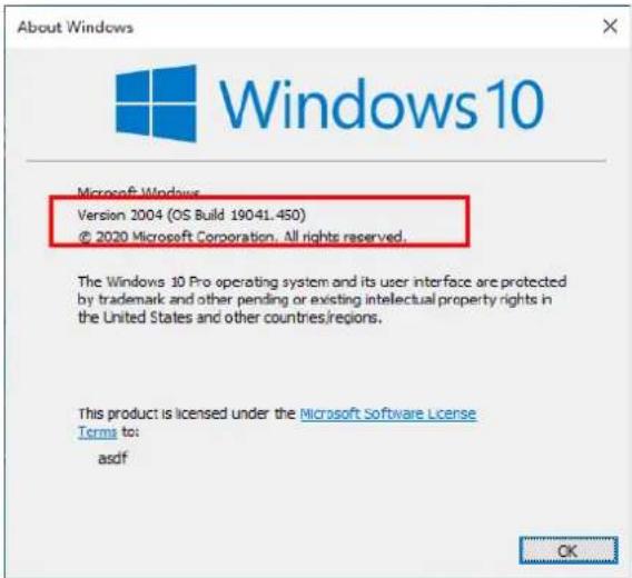
In the red box, your OS version must be 1607 or higher.
If your version is 1607 or below, please proceed to section "5.2. Update Windows".
5.2. Windows Update
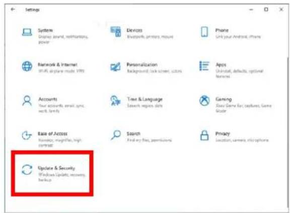
If your Windows 10 version is 1607 or below, you must update Windows. Run "Windows Setup" with the "Windows (☐) + I" shortcut keys.
Under "Set up Windows" select "Update and Security"
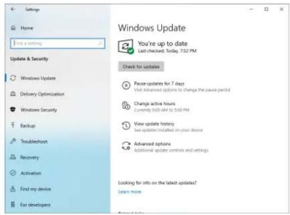
Click "Check for updates" and if there are any updates, proceed with the update. Your PC may reboot several times during a Windows update.
5.3. Display Setting
If the program does not show all the menu options above, right-click on the desktop and go to "Display Settings".
At the "Scale and layout" section, set the following settings:
- "Change the size of text, apps, and other items" into "100%".
• "Display resolution" into "1920x1080"
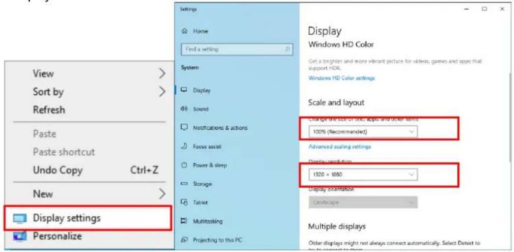
* Resolution: Recommended resolution is 1920*1080 and 1600*900 resolution.
In other resolutions (1680*1050, 1600*1024, 1440*900, 1400*1050, 1366*768, 1360*768, 1280*1024, 1280*960, 1280*800, 1280*768, 1280*720, 1280*600, 1176*664, 1152*864, 1024*768, 800*600), all FSM screens are visible, but the long menus may not display all letters.
DW E.S.T. (Elevated Skin Temperature) System
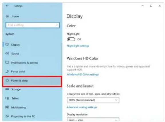
5.4. Power and Sleep
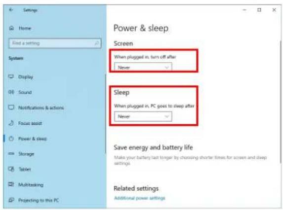
For proper usage of the software, make sure the PC's sleep and power settings are configured as below:
- Click on "Power and Sleep" in the left menu
- "Screen" → "When plugged in, turn off after"
- "Sleep" → "When plugged in, PC goes to sleep after"
- For both items, select "Never" as shown in the screen below.
6. Software Download and Installation
6.1. Download Software and Camera Network Configuration
- Install the Elevated Skin Temperature System_x.x.x.x_Setup.exe. The software is available on Digital Watchdog's website.
a. Go to http://www.digital-watchdog.com
b. Search for 'EST software' in the search bar at the top of the page.
c. The latest software will appear in the search results. Click on the link to download the file to your computer and run the installation file.
- Connect the Camera to the monitoring PC via LAN cable directly (CAT.5E UTP cable).
- When the camera connects directly to the PC, the following is assigned to the camera by default:
• Default Camera IP address: 169.254.100.100
• Default Subnet mask: 255.255.0.0
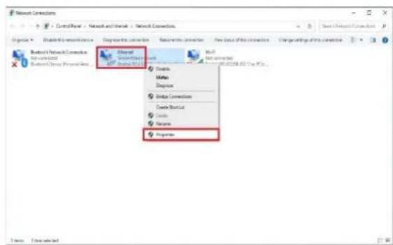
- Open the execution window on the monitoring PC by pressing the "Windows (☐) + R" keys.
- Enter 'ncpa.cpl' and press the 'Enter' key.
- Right-click on 'Ethernet' and select 'Properties' from the drop-down options.
- Double-click on 'Internet Protocol version 4 (TCP/IPv4)' in the Properties window.
- Enter the IP and subnet mask as shown below and click the 'OK' button.
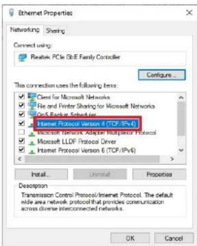
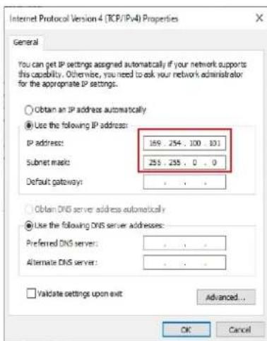
NOTE: Make sure the PC's IP address is not overlapping with the camera's IP address. The PC's IP setting ranges arbitrarily from 169.254.100.1 \~ 169.254.100.254. Make sure to set the subnet mask to 255.255.0.0.
- Click the 'OK' button in the Ethernet Properties window to close the window.
- To test the connection with the camera, open the execution window by using "Windows Key (☐) + R" on the keyboard.
- Enter 'cmd' in the execution window and press the 'Enter' key.
- Enter 'ping 169.254.100.100' (if the camera has been manually assigned to a different IP address, enter that IP instead) and press the 'Enter' key.
![Microsoft kindows [Version 18.8.19041.264] (3) 2008 Microsoft Corporation. 411 rights reserved. C:\Users\unersping 169.254.100.100 Peging 169.254.100.100 with 33 bytes of data: Reply from 169.254.100.100: bytes=32时刻mic TTL=64 Reply from 169.254.100.100: bytes=32时刻mic TTL=64 Reply from 169.254.100.100: bytes=32时刻mic TTL=64 Reply from 169.254.100.100: bytes=32时刻mic TTL=64 Peging statistics for 169.254.100.100: Packets: Sum = A, Received = A, Lost = 0 (US loss), Average: Round trip times in milli-seconds: Minimum = 0ms, Maximum = 0ms, Average = 0ms C:\Users\user>](/content/2026/06/1199180/images/aa3297298defb7727d45fbe78e429b399c1769c7c4e4ff2898036ca5af95dd0a.jpg)
![Microsoft Windows [Version 10.8.10041.264] (3) 2000 Microsoft Corporation. 413 rights reserved. C:\Users\unersping 169.254.100.105 Playing 169.254.100.105 with 33 bytes of data: Reply from 169.254.100.100: Destination Host unreachable. Reply from 169.254.100.100: Destination Host unreachable. Reply from 169.254.100.100: Destination Host unreachable. Reply from 169.254.100.100: Destination Host unreachable. Ping statistics for 109.254.100.100: Packets: Sent = 4, Nused = 4, lost = 8 (US loss). C:\Users\user>](/content/2026/06/1199180/images/b62c9acb5782ae2c55edd6f3f2191ff5f3261952b9f2d89f508c747156fbc13f.jpg)
<Connection failed. If this happens,
change the LAN cable and check
the subnet mask.>
DW E.S.T. (Elevated Skin Temperature) System
6.2. Install the Software
Run "Elevated Skin Temperature System_x.x.x.x_Setup.exe" to install. Click "Next" and review the installation information. You can review the components installed and choose a different directory to install the file.
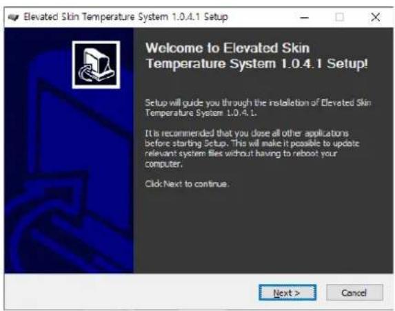
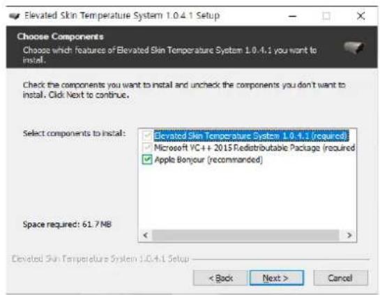
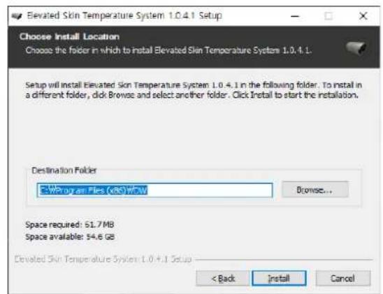
Click "Install" to start the installation. The progress bar will show the installation status.
If an additional installation window opens for a "Bonjour" installation, please complete the installation steps within that window as well.
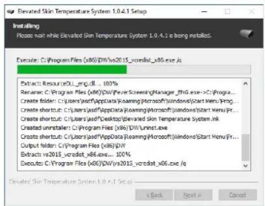
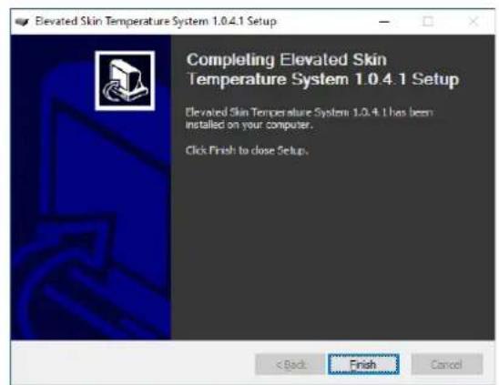
Once the installation is complete, a shortcut icon will appear on the PC desktop and in the Start Menu.
7. Program Installation
Double-click on the software shortcut on the desktop to launch the software.
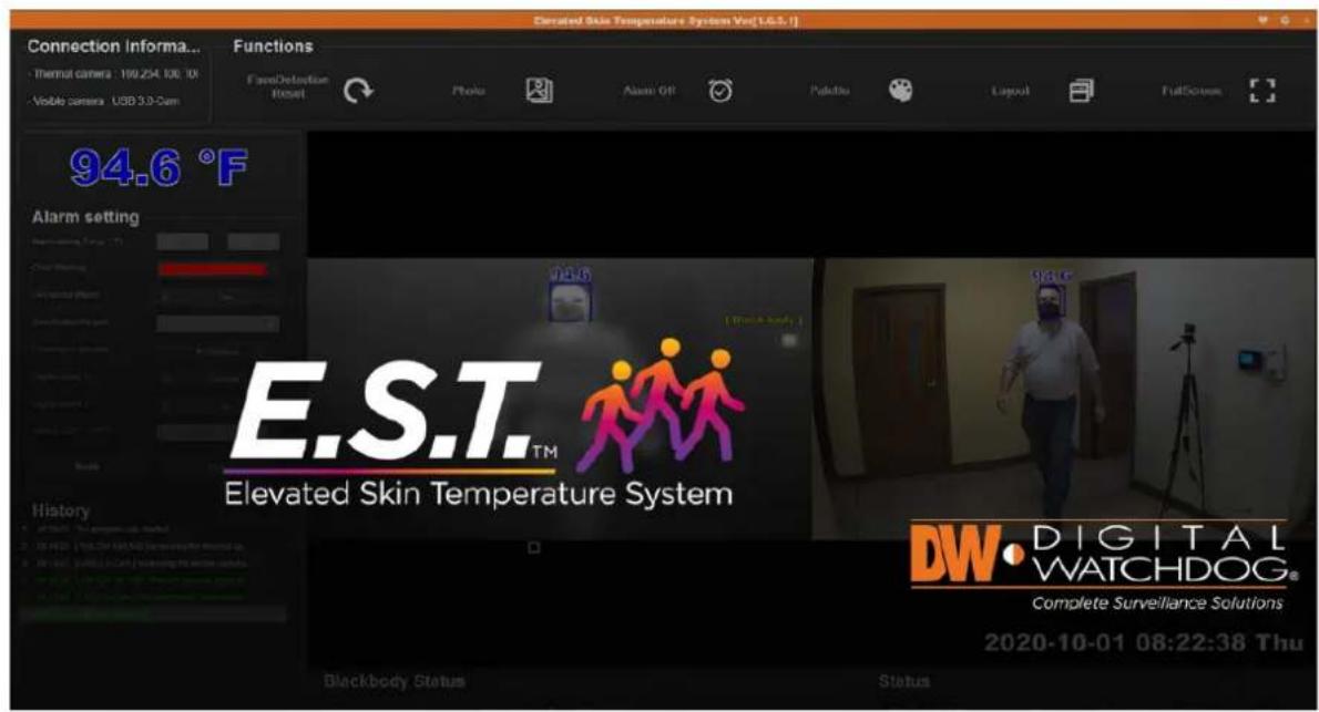
When launching the software for the first time, select whether your installation includes a Blackbody or not.
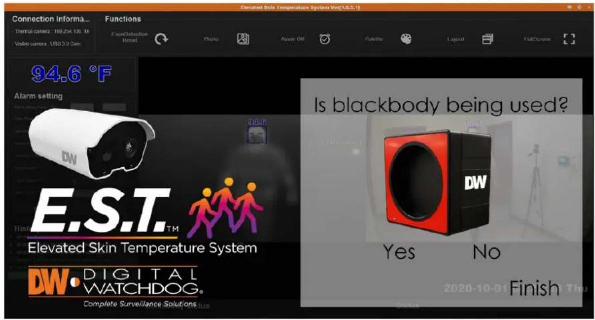
Select "Yes" if there is a Blackbody on-site for constant auto-calibration based on the 104°F (40°F) temperature of the Blackbody.
Select "No" if the installation includes the camera only, and there is no on-site Blackbody for constant auto-calibration.
Click "Finish" to save the selection and launch the software.
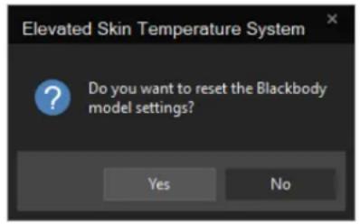
To change your Blackbody selection, press the "Model Reset" button in the top-right of the launch screen. The pop-up window below will appear. Click "Yes" to enter the Blackbody setup screen.
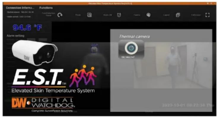
Once the thermal camera is connected to the PC via an Ethernet cable, and the visible camera is connected to the PC via the included USB cable, the following screen will show all the cameras currently connected to the monitoring PC.
If the thermal camera is not listed:
- Check the network setup status.
- Check the LAN cable is connected properly to the camera and the PC.
- Make sure the Wi-Fi on the PC is disabled.
- Reboot the PC and the camera.
If the visible camera is not on the list:
-
Check the USB 3.0 cable is properly connected to the PC.
-
Check if the camera through the Windows "Camera" application.
Click on the thermal camera button to access the camera's view. The number of thermal camera icons available will reflect the number of cameras connected to the monitoring PC.
Once the camera is selected, the software runs the initialization process.
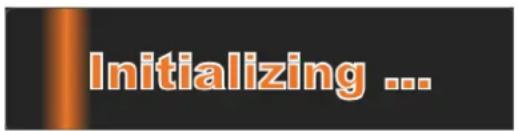
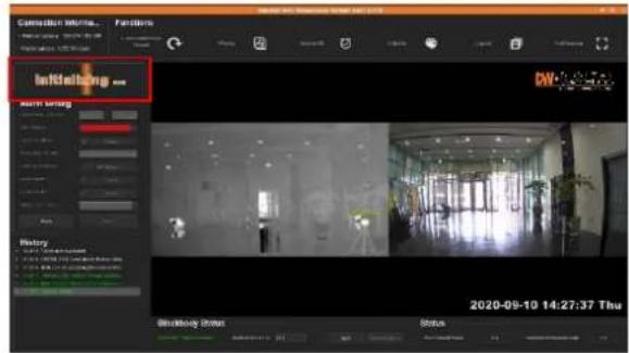
※ When the program starts, "Initializing..." is displayed in the upper left temperature display section, until initialization is complete.
DW E.S.T. (Elevated Skin Temperature) System
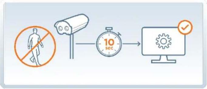
Note: For better recognition, keep people and objects out of the camera's field of view for 10 seconds. The initialization process takes 3-10 seconds, depending on the in-image state. Once the "Initializing..." disappears from the monitor, the system is ready to start reading facial skin temperature.
flowchart
graph LR
    A["No Significant"] --> B["Camera"]
    B --> C["10 sec"]
    C --> D["Computer Interface"]
    D --> E["Checkmark"]
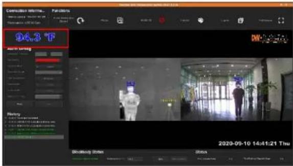
Once the initialization process is complete, the face is detected and the temperature is displayed on the detected faces as shown below.
![Connection Informa... Thermal camera: 169.254.100.100 Visible Camera: USB 3.0-Cani Functions Face Detection Format Photo Alarm Off Palette Layout FullScreen Alarm setting Alarm setting Temp (°C) Color Warning Size sound effects Disksis Sound effect size Lighting in instance Digital output Digital output 2 Other (-20.5" -20.5").- Modify Actions History 12:48:16 The progress heat states 12:48:16 [USB 3.0-Cani Accessing the thermal camra... 12:48:16 [USB 3.0-Cani Accessing the electrical cameras... 12:48:17 [USB 3.0-Cani (thermal sensors) condition... 12:48:18 [USB 3.0-Cani (w/o devices) condition...] 2020-09-10 14:27:37 Thu Blackbody Status Blackbody Detection Status Stablebody temp (°C): 40.3 Alert Status - Alarm Capacity Usage - Face Detection Capacity Usage - 0% - Final Capacity Usage](/content/2026/06/1199180/images/0306b79450c8a150bfa623e80a072d239e7dd604cefb6298daad81004fd61ee3.jpg)
8. Software Elements
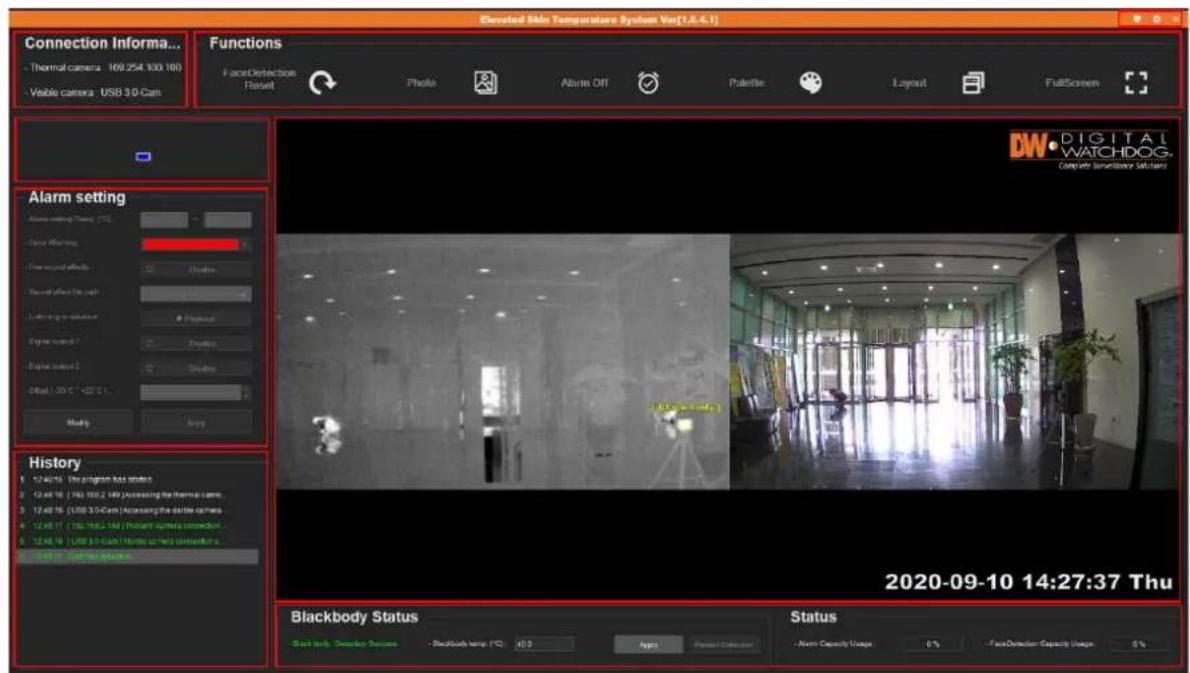
| Elements | Description |
| Connection Information | Display the thermal and visible camera information. |
| Function | Enable or disable the alarm, capture a JPEG, change palette color, or adjust the layout. |
| Temperature Display | Show the current recorded temperature. When more than one person is being scanned, the highest temperature detected is displayed. |
| Alarm Setting | Adjust the settings for the temperature threshold, alarm output, and color. |
| History | Logs and event history related to the program. |
| Top Navigation Bar | Control the software's settings, monitor, and close the window. |
| Main View | Main display. Shows the selected screen layout. |
| Blackbody Status | Status of Blackbody and disk usages of folders for images when a face is detected and when an alarm is generated. |
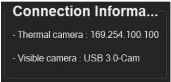
8.1. Connection Information
This section, located on the top left of the screen, shows the connection information for both the thermal and visible camera
8.2. Functions
DW E.S.T. (Elevated Skin Temperature) System
The "Functions" bar includes the software's settings below:


1. Face Detection Reset
If facial detection is not working properly, or the camera's orientation was changed, use this button to restart the "Initializing..." process. During the process, the "Initializing..." term will appear in the software's view.
Note: It is recommended to start the "Face Detection Reset" with no people in the camera's view. Keep people and moving objects away 32ft (10m) from the camera's view for 3-10 seconds as the cameras adjust.
2. Photo

Save a JPEG image of the current view. The saved image will appear in the History log on the bottom-left. Click on the folder icon to open the folder location on the computer. Click on the image icon to open the captured image.
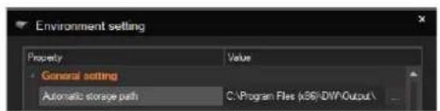
To change the directory where the images are saved, click the "Settings" button on the top navigation bar. Under General Settings, click on "Automatic Storage Path" and click on the "... button on the right.
The file name format depends on the date/time format set in the settings buttons on the top navigation bar:
• YYYY/MM/DD: FSM Export YYYMMDD HHMMSS.JPG
• MM/YYYY/DD: FSM_Export_MMYYYYDD_HHMMSS.JPG
• DD / MM / YYYY: FSM_Export_MMDDYYYY_HHMMSS.JPG

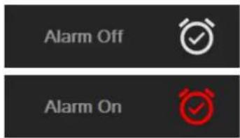
3. Alarm On/Off
Enable or disable the alarm connected to the camera.
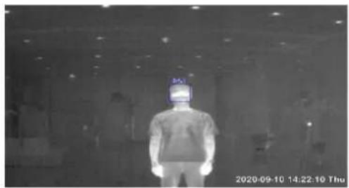
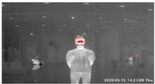
When the "Alarm On" setting is selected, a JPEG is captured automatically when the temperature above the set threshold is detected.
When the "Alarm On" setting is selected, the pixels in the "Alarm Setting Temp." range are displayed in color.
natural_image
Person standing in a dimly lit room with a monitor displaying '30.5' (no visible text or symbols on the person or background)<“Alarm Off” state>
natural_image
Thermal image of a person in full protective suit standing indoors, with no visible text or symbols<“Alarm On” state>

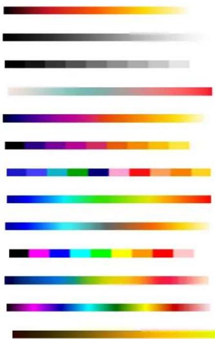
4. Palette
Use this setting to adjust the color palette showing the temperature distribution on the thermal camera's images. The default palette is grey.
- Glowbow:
- Grey:
- Grey10:
- GreyRed:
- Iron:
- Iron10:
• Medical: - MidGreen:
- MidGrey:
- Rain10:
- Rain900:
- Rainbow:
- Yellow:
natural_image
Color swatch bar with gradient from black to yellow (no text or symbols)
5. Layout
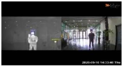
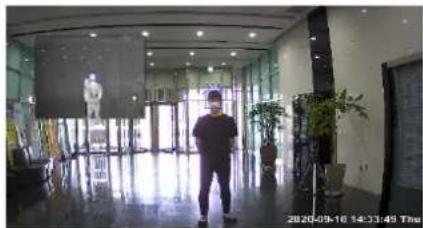
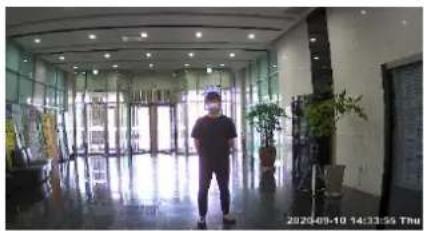
The E.S.T. thermal and visible camera views can be used in multiple layout options to optimize your user experience. The available options include a split view, PIP mode, visible camera only, and thermal camera only.
natural_image
Interior view of a modern hallway with two individuals in protective suits, no visible text or symbols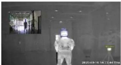
natural_image
Interior view of a modern hotel lobby with glass doors, potted plants, and a person walking (no visible text or signage)- You can adjust the position and sizing of the thumbnail image using the mouse cursor.
natural_image
Interior view of a modern hotel lobby with glass doors, potted plants, and a person standing in the aisle (no visible text or signage)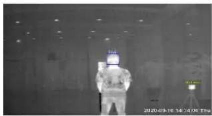
natural_image
Thermal image of a person in full-body view with visible heat signatures and equipment (no text or symbols)
6. Full Screen
View the main view in full screen. Press the Esc key to exit full-screen mode.
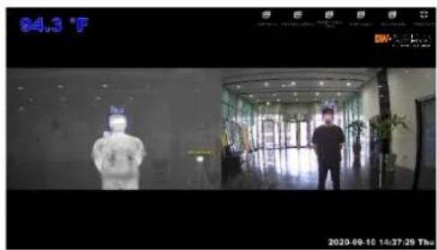
Saving JPEG files and output alarm signals will function the same regardless of the "Full Screen" mode.
8.3. Maximum Temperature Indication Window
The temperature section on the left of the software's view shows the temperature measured currently. During the software's initializing period, "Initializing..." is displayed in this section.
If no people or no faces are detected in the camera's FOV for skin temperature measurement, the image below will display.

natural_image
A single blue square centered on a dark background, no text or symbols present.When there are multiple people in the camera's FOV, the section will show the highest skin temperature recorded.
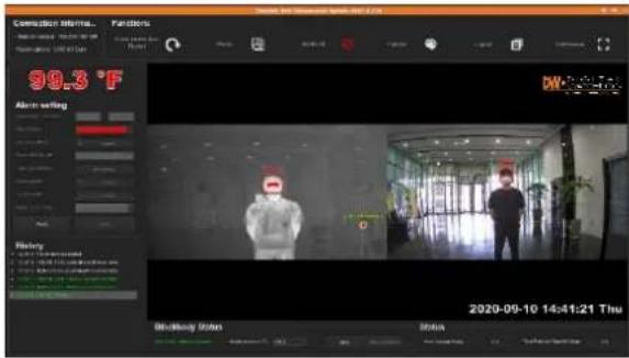
If “Alarm On” is selected on the function bar, the color of the text will change as the detected skin temperatures fall within the set threshold, above the threshold, or below the threshold.
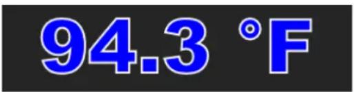

Note: If "Alarm Off" is set on the function bar, the temperature values shown here will remain blue even if they fall outside of the set threshold.
8.4. Alarm setting
This section, located on the center-left side of the software is enabled when "Alarm On" is selected in "Function". To edit any of the settings in this section, "Modify" must be selected first.
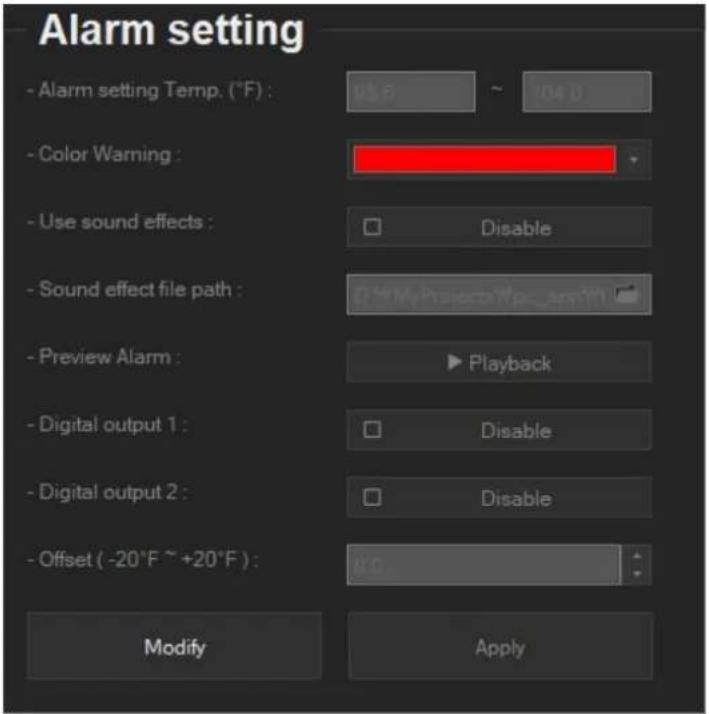
| Setting | Description | |
| Alarm Setting Temp (°C) | Set the minimum and maximum temperature range that would trigger an alarm.The maximum temperature cannot be changed and is set by default to 104°F (40°C).NOTE: Measurements captures within the set threshold will trigger an alarm. | |
| Color Warning | Select the warning color from the available drop-down options.When an alarm occurs, the face detection box and the measured face temperature on the temperature field will change to the set color.By default, the warning color is set to red.NOTE: All pixels whose temperature falls within the “Alarm setting Temp.” range are expressed in the color set in the “Color Warning”. | 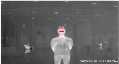 |
| Use Sound Effect | Enable or disable an audio alarm when the temperature is detected within the “Alarm setting Temp.” range. | |
| Sound Effect File Path | If “Use sound effects” is enabled, select the audio sound file to play when the alarm is triggered. Click the folder button and find the audio file in the directory path of your PC.The default audio file is "warning_sound.select wav"The software supports .wav and .mp3 file formats.Only short and simple sound effects can be used. (No songs, no classical music, etc.) | |
| Listening in Advance | Listen to the file that is set as a sound effect. | |
| Digital Output 1 and 2 | Set the camera's two (2) alarm outputs when an alarm is triggered.Alarm port 1 (Digital output port #4 and #5)Alarm port 2 (Digital output port #6 and #7. Assigned to LED strobe).The camera comes with an LED strobe connected to Alarm Port 2. When an alarm is triggered, the LED connected to alarm port 2 flashesYou can also enable a digital output signal transmitted to an external alarm device connected to the camera's alarm ports. | |
| Offset | Adjust the temperature displayed on the screen. You can offset the temperature values by as much as 68°F (20°C).Recorded facial skin temperature is usually around 92.3°F (34°C). The human body temperature is usually at 96.8°F (36°C). Use the offset value by increasing the temperature offset by 2 degrees Celsius.NOTE: If Offset is used, the alarm setting temp should be adjusted by the same values. | |
| Modify | This button must be selected to make the settings above open for editing. | |
| Apply | Apply all changes to the settings | |
8.5. History
The "History" panel on the bottom-left shows the activity log for the software. This includes Alarm, Face Detection, and JPEG exports.
![History 1 16:52:46 The program has started. 2 16:52:46 [ 192 168.2.149 ] Accessing the thermal came... 3 16:52:46 [USB 3.0-Cam ] Accessing the visible camera... 4 10:52:46 [ 192 108.2.149 ] Theramil camera connection ... 5 16:52:47 [USB 3.0-Cam ] Visible camera connection s... 6 16:52:53 Startface detection](/content/2026/06/1199180/images/a5db90c938d5c75388f1e9ca3c305a21cc9fba6c2f53e7c262378ccc48a4d65f.jpg)
![History 1 16:52:46 The program has started. 2 16:52:46 [ 192 168.2 149 ] Accessing the thermal came... 3 16:52:46 [ USB 3.0-Cam ] Accessing the visible camera... 4 16:52:46 [ 192 108.2 149 ] Theramil camera connection ... 5 16:52:47 [ USB 3.0-Cam ] Visible camera connection s... 6 16:52:53 Start face detection. 7 16:53:13 Picture has been saved. 8 16:53:16 The alarm has been turned on. A 16:53:16 Alarm is an @ngood Data/Dating, 10.0°C, T](/content/2026/06/1199180/images/3cec61f9fbf9b3a7d3f8e31899d75419e7ecaeb20598ab7ffbb3939a8d171779.jpg)
For JPEG exports, a folder and image buttons are available to view the directory where the image is saved and open the image itself.
8.6. Top Navigation Bar
The top navigation bar, located on the top of the window in orange, includes the settings for Monitor Selection, Software Settings, and Exit the software.
The software settings popup window includes the following settings:
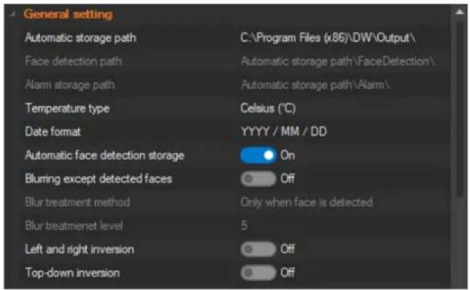
| Setting | Description |
| Automatic storage path | Specify the path where JPEG files are saved.The default path is: C:\Program Files(x86)\DW\Output\ |
| Face detection path | Specify the path where JPEG files saved when a face is detectedThe default path is: C:\ProgramFiles(x86)\DW\Output\FaceDetection\YYYYMMDD\ |
| Alarm storage path | Specify the path where JPEG files are saved when an alarm is triggered.The default path is C:\Program Files(x86)\DW\Output\Alarm\YYYYMMDD\ |
| Temperature type | Set the temperature format to Celsius (°C) or Fahrenheit (°F). |
| Date format | Select the date and time format from the available options: YYYY/MM/DD, MM/DD/YYYY, or DD/MM/YYYY. |
| Automatic face detection storage | Enable to save images automatically when faces are detected. |
| Blurring except detected faces | Enable blurring for areas other than the face. When enabled, people's bodies are blurred out, keeping only the face clear and detectable. |
| Blur treatment method | Blurring mode can be set to two options:Only when a face is detected and Always. |
| Blur treatment level | Adjust the level of blurring treatment from 5 to 15. The smaller the number, the lower the intensity of the blur treatment. |
| Left and right inversion | Flip the camera's view horizontally. If enabled, a camera reboot is required to apply the settings. |
| Top-down inversion | Flip the camera's view vertically. If enabled, a camera reboot is required to apply the settings. |
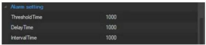
| Setting | Description |
| Threshold Time | The time, in milliseconds, the alarm start condition should be maintained. The alarm will be triggered only after the threshold time conditions are met.Default: 1000ms (1 second) |
| Delay Time | The time, in milliseconds, to delay alarm termination when conditions are not satisfied during alarm occurrence.Default: 1000ms (1 second) |
| Interval Time | The time, in milliseconds, to prevent the next alarm from occurring (prevent alarms too often) after the alarm is closed.Default: 1000ms (1 second) |
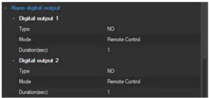
| Setting | Description |
| Alarm 1 and Alarm 2 Type, Mode, Duration (sec) | For each of the available alarm outputs, enter the following. The default settings listed below are recommended.Alarm type: NO (normal open)Mode: Remote controlDuration: 1 second |
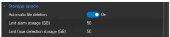
| Setting | Description |
| Automatic file deletion | When the HDD has less than 5% space available, automatically delete old files first. |
| Limit alarm storage (GB) | Set a limit to the amount of storage used for alarm storage. |
| Limit face detection storage (GB) | Set a limit to the amount of storage used for face detection storage. |
8.7. Main Display
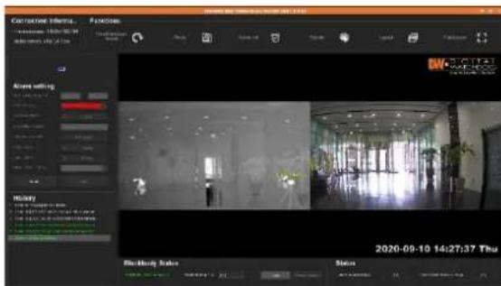
The main view in the center of the software shows the camera's current view, in the layout selected. It also
DW E.S.T. (Elevated Skin Temperature) System
includes the current date and time. If a Blackbody is installed, it will be detected automatically by the software in the camera's view and marked with a yellow frame.
![08:2 [Therometer 1] 2020-09-10 14:38:21 Thu](/content/2026/06/1199180/images/8399c613c369b5aab05cb38e7628308e6c96da0964a793728dd38764757dd75e.jpg)
natural_image
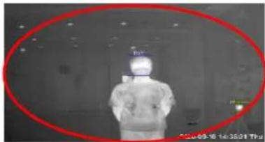
Person in full-body medical attire viewed from behind, with a red oval highlighting the face (no visible text or symbols)The recommended location for the Blackbody installation: The Blackbody cannot be installed in a crowded location. Install the Blackbody within the red ellipse marked within the image on the left. This is the best location for on-site constant auto-calibration for accurate temperature measurements ( ±0.36^ F/0.2°C).
If the mouse cursor is left motionless on the thermal camera's view for more than one second, the system will display the screened temperature for that area.
![[77.0°F] [4.3] (Black body) 2020-09-10 14:38:21 Thu](/content/2026/06/1199180/images/020d97268de789061558a76041510dc1b9f423c074a0dbea4267ba1505ffbb4e.jpg)
8.8. Blackbody Status
The Blackbody status bar at the bottom of the software window will display only if Blackbody was selected as part of the solution when installing the software.

When mounted correctly in the camera's FOV, the Elevated Skin Temperature Software automatically detects the Blackbody's location.
If the automatic detection of the Blackbody fails and "Blackbody Status" continues to display "Blackbody: Detection failed", use your mouse and manually draw a square around the Blackbody. It will appear yellow. Place the square on the Blackbody as seen in the thermal video. You can adjust the size and position of the yellow square as needed by clicking and dragging the yellow square with your mouse.

When the Blackbody is detected manually, the "Blackbody Status" status will change to "Blackbody: Manual Detection". When this occurs, the "Restart Detection" button is activated. Click on it to set the program to find the Blackbody automatically. Once done, "Blackbody: Detection Success" will appear if the software successfully detected the Blackbody, or "Blackbody: Detection Failed" if the software fails to detect the Blackbody.

8.9. Status
Shows the current storage status for both alarm events and face detection events. The limits and file paths can be set on under Environment Settings > Storage Space.
When the usage reaches 95%, old folders will be deleted to make room for new ones.

9. Run Program
DW E.S.T. (Elevated Skin Temperature) System
Once the initializing stage is complete, the facial skin temperature will be displayed when a face is detected.
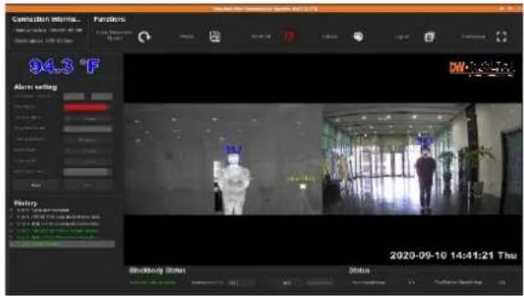
The temperature display will show the highest skin temperature detected. If there is more than one person in the camera's view, each face detected will be framed in a blue frame, with the skin temperature shown for each person.
Below is a simple flow chart that shows events that take place for an alarm to be registered and a JPEG to be captured and saved locally.
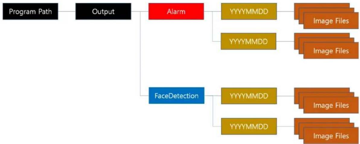
flowchart
graph TD
    A["Program Path"] --> B["Output"]
    B --> C["Alarm"]
    C --> D["YYYYMMDD"]
    C --> E["YYYYMMDD"]
    D --> F["Image Files"]
    E --> G["Image Files"]
    H["FaceDetection"] --> I["YYYYMMDD"]
    H --> J["YYYYMMDD"]
    I --> K["Image Files"]
    J --> L["Image Files"]
10. Specifications
Thermal camera
| Sensor | Micro-bolometer | Uncooled focal plane array |
| Resolution 384 x 288 | ||
| Pixel pitch | 17μm | |
| Response wavelength | 8μm to 14μm | |
| Thermal sensitivity 50mK@f1.0, 30Hz, 300K | ||
| Lens | Lens type Thermalized lens | |
| Focal length 8.13mm f1.16 | ||
| HFOV/VFOV 47.4°/35.1° | ||
| Recommended distance range for best reliable measurement | 6.5 to 16.4ft (2m to 5m). 10ft recommended. | |
| Minimum focus distance | 1.64ft (0.5m) | |
| Data output | Interface | Gigabit Ethernet (10/100) |
| Data | Temperature raw data of each pixel of the thermal sensor | |
| Frame rate 30Hz | ||
Visible camera
| Image sensor | 1/3" Progressive CMOS (Approx. 2.1 mega) | |
| Sensor | Scanning system 16:9 Progressive | |
| Effective pixel | 1920 (H) x 1080 (V) | |
| Minimum scene illumination | 0.2 lux (color), 0.1 lux (B/W) | |
| Horizontal resolution | 1000TVL | |
| Lens | Optic | 4.0mm 70° HFOV |
| Video output | Interface | USB3.0 super-speed |
| Format | USB3.0 UVC compliant YUV 422 16bits, uncompressed video | |
| Resolution and frame rate | 1920x1080p @ 30fp | |
General Camera
| Operation | Weight | 2.2 lbs. (1000 gr.) including USB cable from the visible camera |
| Dimension (H x W x D) | 3.18" x 5.31" x 5.92" (81 x 135 x 150.5mm) | |
| Power supply | 12V DC | |
| Operation Temperature | 14°F ~ 104°F (-10°C ~ 40°C) |
Blackbody
| Blackbody | Fixed temperature set at the factory | 104°F (40°C) |
| Effective radiant surface | 55 | |
| Temperature resolution | 0.01 | |
| Temperature stability | ±0.18°F (±0.1°C) | |
| Temperature accuracy | ±0.36°F (±0.2°C) | |
| Emissivity 0.95 | ||
| Temperature sensor NTC 0.1% | ||
| Weight 0.72 lbs. (330 gr.) | ||
| Dimension (H x W x D) | 2.83 x 2.83 x 1.92" (72 x 72 x 49mm) | |
| Power supply | 110/220 VAC to 12VDC adaptor 36W(3A), 90° angle jack | |
| Recommended distance from the camera | Between 9.8 to 14.7ft (2m to 4m). 10ft is recommended. Install Blackbody at 9.8 to 14.7ft (2m to 4m) apart from the camera on a tripod, the wall, or the ceiling. The closer people walk by the Blackbody, the more accurate the temperature reading will be). | |
| Recommended installation height | 5ft | |
| Operation Temperature | 14°F ~ 104°F (-10°C ~ 40°C), under 80% humidity | |
| Warranty 2 year warranty | ||
* Specifications are subject to change without notice.
NOTE: To increase the skin temperature measurement accuracy, the camera transmits raw temperature data of all the pixels in the thermal sensor to the PC software via the Ethernet cable. The Elevated Skin Temperature Software program processes the raw data using the PC's processing capacity.
If the installation includes a Blackbody, the temperature data in each pixel is calibrated based on the 104°F (40°C) temperature of the Blackbody. This increases the system's accuracy up to ±0.36°F/0.2°C.
The Elevated Skin Temperature Software program performs various analyses to mark a person's faces and skin temperature, on images from both the visible and thermal cameras.
11. FAQs
11.1. Usability
- How does thermal imaging technology work?
a. Skin temperature pre-screening cameras detect the skin's heat radiation. When used properly, DW's E.S.T. cameras can be used as a non-contact pre-screening tool to detect differences in skin surface temperatures.
- Can DW's EST system be used to detect a virus such as the novel Coronavirus (COVID-19)?
a. No, thermal imaging and skin temperature capturing cameras cannot be used to detect or diagnose an infection. DW's E.S.T. cameras can be deployed in public spaces such as school entrances, airports, and hospitals as an effective tool for measuring skin surface temperature. People identified as having an elevated skin temperature should then be screened by medical professionals using additional tools such as a thermometer and a health questionnaire.
- Can I use the camera to get alerts without connecting it to a VMS, just with a laptop and browser?
a. The camera comes with an LED strobe included that can be mounted on the camera or next to it. Also, the camera has an additional alarm output that can be triggered by a temperature event.
- Do I need to use a switch with the camera to connect it to a PC and can I use a PoE switch?
a. You do not need an additional switch or PoE switch for the camera. Connecting the camera directly to the PC lets the camera transmit the raw pixels directly and instantly to the PC.
- How should skin temperature screening be performed?
a. The U.S. Food and Drug Administration (FDA) provides full recommendations for Thermal Imaging Systems (Infrared Thermographic Systems / Thermal Imaging Cameras). Here are several tips to ensure optimal measurement performance:
- Screen people, one at a time to look for temperature anomalies.
- Screen people from 10 to 16.4 feet away.
The camera measures the skin temperature near the tear duct. This location provides the closest temperature match to the human core body temperature.
IMPORTANT: This is not measuring core body temperature and readings near 35°C (95°F) are common.
○ Perform a secondary screening on individuals with elevated skin temperature using a medical device such as a thermometer and a health questionnaire.
- How many peoples' temperatures can be measured at the same time?
a. In compliance with industry standards and to achieve specified accuracy, 1 face at a max of every 4 seconds.
- How accurate is the temperature measurement?
a. With Blackbody, the camera has a temperature accuracy of +/-0.36°F (+/-0.2°C).
- Can the camera measure in both Celsius and Fahrenheit?
a. Users can customize their view on the monitoring software by selecting the temperature values as Celsius or Fahrenheit. The software will display the measured temperature in the selected option.
- Is it possible to switch a relay in the camera when a high temperature is detected?
a. Users can select Normally Open or Normally Closed activation of a relay. The monitoring software will display the selected preference.
- Can the camera work outside?
a. It is recommended to set your screening station indoors. Solar loading or reflection could cause
false alarms and measurements.
b. If an outdoor deployment is the only option, both the camera and Blackbody need to be installed under a shelter. The temperature around the camera and Blackbody should be between 50^ F – 95^ F ( 10^ C – 35^ C).
NOTE: the Blackbody is NOT rated as an outdoor device.
- Do I need to display specific signage to alert customers that their temperature is being measured? a. Check with your local government guidelines. Each location may have different standards and requirements for public notification. Users are responsible for compliance with any local standards and requirements.
11.2. Hardware Related
- What does the Blackbody do and why do I need it?
a. A Blackbody is a sensor that constantly emits a heat signature between 0.90\~0.99. It is used as a reference source for the camera. When placed across from the camera, at the corner of the camera's FOV, it helps maintain the camera calibrated at all times, increasing data accuracy. Once the Blackbody is mounted properly in the camera's FOV, the E.S.T. monitoring software auto-calibrates in real-time with the temperature from the Blackbody and uses this to provide automatic, ongoing calibration and thermal drift management. This helps reduce false alarms and error readings.
- Do I need a Blackbody for the camera?
a. The E.S.T. solution can be purchased as a complete kit, with one Blackbody and one camera. You may purchase a camera without the Blackbody. All DW cameras come calibrated from the factory. It is highly recommended to use at least one Blackbody per installation to guarantee proper calibration and accurate data is collected.
- How do I test the camera to see if it is reading the temperatures correctly?
a. A comparison test with a handheld thermometer can be done at the site to verify the camera's accuracy.
- How often do I recalibrate the camera?
a. All cameras are calibrated by default at the factory. Once mounted with the Blackbody, the camera can perform the calibration automatically and in real-time. It is recommended to calibrate your camera at least once a week for optimal performance. Users can also use the monitoring software to re-detect the Blackbody in the camera's FOV should there be any detection issues.
- Does the camera need any type of software support agreement?
a. There is no need for a software support agreement for the camera itself. A 2-year warranty is included for the camera; however, a software support agreement is needed for the Video Management System platform if the camera is integrated.
11.3. Compatibility
- Which Video Management Systems is the camera compatible with?
a. The camera is compatible with DW's E.S.T. monitoring software. This is a standalone solution that can be installed on any computer running Microsoft OS.
- Can I connect my E.S.T. Solution to an Access Control system?
a. Yes, the camera has an output which switches on alarm. This output can be connected to and access control system controller which has input available.
- Does it also work with facial recognition AI?
a. No. The camera uses face detection to perform temperature testing but does not support Facial Recognition.
11.4. Compliance
- Is the solution classified as a medical device?
a. No. In the USA, the camera and Blackbody have been designed to meet the U.S. Food & Drug Administration's April 2020 Enforcement Policy for Thermographic Systems. However, it is NOT classified as a medical device and is not intended to detect or diagnose a disease or any health conditions. The product is intended to use as a first-line filter to identify people entering a facility who may have an elevated body temperature. If elevated skin temperature is detected, organizations should always follow up with additional screening with medical devices such as a thermometer and medical questionnaire. Organizations should then determine the appropriate action for that information. Temperature measurements should not be the only or primary tool of diagnosis or exclusion diagnosis of COVID-19 or any other disease.
12. Warranty Information
Digital Watchdog (referred to as “the Warrantor”) warrants the Camera against defects in materials or workmanship as follows:
Labor: For the initial two (2) years from the date of the original purchase if the camera is determined to be defective, the Warrantor will repair or replace the unit with a new or refurbished product at its option, at no charge.
Parts: Also, the Warrantor will supply replacement parts for the initial two (2) years.
To obtain warranty or out of warranty service, please contact a technical support representative at 1+ (866) 446-3595, Monday through Friday from 9:00 AM to 8:00 PM EST.
A purchase receipt or other proof of the date of the original purchase is required before warranty service is rendered. This warranty only covers failures due to defects in materials and workmanship which arise during normal use. This warranty does not cover damages which occurs in shipment or failures which are caused by products not supplied by the Warrantor or failures which result from accident, misuse, abuse, neglect, mishandling, misapplication, alteration, modification, faulty installation, setup adjustments, improper antenna, inadequate signal pickup, maladjustments of consumer controls, improper operation, power line surge, improper voltage supply, lightning damage, rental use of the product or service by anyone other than an authorized repair facility or damage that is attributable to acts of God.
13. Limits and Exclusions
There are no express warranties except as listed above. The Warrantor will not be liable for incidental or consequential damages (including without limitation, damage to recording media) resulting from the use of these products, or arising out of any breach of the warranty. All express and implied warranties, including the warranties of merchantability and fitness for a particular purpose, are limited to the applicable warranty period set forth above.
Some states do not allow the exclusion or limitation of incidental or consequential damages or limitations on how long an implied warranty lasts, so the above exclusions or limitations may not apply to you. This warranty gives you specific legal rights, and you may also have other rights from vary from state to state.
If the problem is not handled to your satisfaction, then write to the following address:
Digital Watchdog, Inc.
ATTN: RMA Department
16220 Bloomfield Ave
Cerritos, CA 90703
Service calls that do not involve defective materials or workmanship as determined by the Warrantor, in its sole discretion, are not covered. The cost of such service calls is the responsibility of the purchaser.
DW• DIGITAL WATCHDOG®
Complete Surveillance Solutions
DW® East Coast office and warehouse: 5436 W Crenshaw St, Tampa, FL USA 33634 DW® West Coast office and warehouse: 16220 Bloomfield Ave, Cerritos, CA USA 90703
PH: 866-446-3595 | FAX: 813-888-9262
www.Digital-Watchdog.com
technicalsupport@dwcc.tv
Technical Support PH:
USA & Canada 1+ 866-446-3595
International 1+ 813-888-9555
French Canadian: + 1-904-999-1309
Technical Support Hours: Monday-Friday 9 a.m. to 8 p.m. Eastern Time
Revision history
| Ver. | Date | Writer | Contents |
| 1.0 | 2020.06.15 | D. I. Kim | First release |
| 1.1 | 2020.07.02 | D. I. Kim | Modified for adding new features |
| 1.2 | 2020.07.03 | D. I. Kim | Modified for adding new features |
| 1.3 | 2020.08.13 | D. I. Kim | Modified for adding new features |
| 1.4 | 2020.08.18 | D. I. Kim | Modified for adding display setting |
| 1.5 | 2020.08.20 | D. I. Kim | Modified for adding new features |
| 1.6 | 2020.09.03 | H. S. Lee | Modify the relevant parts for adding features(Programming selection based on camera type and whether or not the Blackbody is included) |
| 1.7 | 2020.09.25 | Debbie G. | Proofreading and formatting to DW style. |
- Contents
- What's in the Box
- Camera Connection
- Installation Diagram and Considerations
- Installation Diagram
- Installation Considerations
- Monitoring PC System Requirements
- Hardware
- Installation Environment Before Installation
- Check Windows 10 Version
- Windows Update
- Display Setting
- Power and Sleep
- Software Download and Installation
- Download Software and Camera Network Configuration
- Install the Software
- Program Installation
- Software Elements
- Connection Information
- Functions
- Face Detection Reset
- Photo
- Alarm On/Off
- Palette
- Layout
- Full Screen
- Maximum Temperature Indication Window
- Alarm setting
- History
- Top Navigation Bar
- Main Display
- Blackbody Status
- Status
- Run Program
- Specifications
- FAQs
- Usability
- Hardware Related
- Compatibility
- Compliance
- Warranty Information
- Limits and Exclusions
- DW• DIGITAL WATCHDOG®
- Complete Surveillance Solutions
Brand : Digital Watchdog
Model : Elevated Skin
Category : Camera