
ERF-PC03 - Unspecified SONY - Free user manual and instructions
Find the device manual for free ERF-PC03 SONY in PDF.


| Product Name | AIBO Master Studio ERF-PC03 |
| Product Type | Robot Programming Software Suite |
| Compatible AIBO Models | ERS-210, ERS-220, ERS-310 series |
| Operating Systems | Microsoft Windows XP, Windows 2000 Professional (SP1+), Windows Millennium Edition, Windows 98 Second Edition (English/French/German/Chinese editions) |
| CPU Requirement | Intel MMX Pentium 300 MHz or higher |
| RAM Requirement | 64 MB or greater |
| Hard Disk Space | 120 MB or greater |
| Display Requirement | 800 × 600 pixels or higher, High Color (16-bit) or greater |
| Sound Requirement | Sound chip compatible with OS, or sound card and speakers (for creating/checking AIBO sounds) |
| Memory Stick Requirement | Built-in Memory Stick drive or Memory Stick reader/writer |
| Wireless LAN (Optional) | Wireless LAN PC card or access point compliant with IEEE 802.11b (for ERS-210/220 only) |
| Included Accessories | CD-ROM, Programming Memory Stick (ERA-MS008) with case and labels, End-User License Agreement, User's Guide, Tutorial Guide, Key code sticker (set of two) |
| Languages | English, French, German, Chinese (printed materials and UI) |
| Main Components | AIBO Master Studio Setup, Quick Behavior Arranger, Behavior Arranger, Action Composer |
| Key Features | Voice recognition, sound recognition (media link sounds, tonal scales), LED control, motion editing, MIDI/WAVE support, wireless LAN transfer, subroutine creation, variable support |
| Regulatory Compliance | FCC Part 15 (Class B), Canadian ICES-003, CE (EMC) EN55022 |
| Copyright | ©2002 Sony Corporation. All rights reserved. |
Frequently Asked Questions - ERF-PC03 SONY
User questions about ERF-PC03 SONY
0 question about this device. Answer the ones you know or ask your own.
Ask a new question about this device
Download the instructions for your Unspecified in PDF format for free! Find your manual ERF-PC03 - SONY and take your electronic device back in hand. On this page are published all the documents necessary for the use of your device. ERF-PC03 by SONY.
USER MANUAL ERF-PC03 SONY
For the customers in U.S.A.
This device complies with Part 15 of the FCC Rules. Operation is subject to the following two conditions: (1) This device may not cause harmful interference, and (2) this device must accept any interference received, including interference that may cause undesired operation.
For the customers in Canada
This Class B digital apparatus complies with Canadian ICES-003.
This equipment has been tested and found to comply with the limits for a Class B digital device, pursuant to Part 15 of the FCC Rules. These limits are designed to provide reasonable protection against harmful interference in a residential installation. This equipment generates, uses, and can radiate radio frequency energy and, if not installed and used in accordance with the instructions, may cause harmful interference to radio communications. However, there is no guarantee that interference will not occur in a particular installation. If this equipment does cause harmful interference to radio or television reception, which can be determined by turning the equipment off and on, the user is encouraged to try to correct the interference by one or more of the following measures:
- Reorient or relocate the receiving antenna.
- Increase the separation between the equipment and receiver.
- Connect the equipment into an outlet on a circuit different from that to which the receiver is connected.
- Consult the dealer or an experienced radio/TV technician for help.
You are cautioned that any changes or modifications not expressly approved in this manual could void your authority to operate this equipment.
For Customers in Europe
CE (EMC) Marking Conformity Remarks
a) This equipment complies with EN55022.
Class B digital for use in following areas: residential, business, and light-industrial.
b) This product conforms with the following European Directive:
89/336/EEC (EMC directive)
©2002 Sony Corporation All rights reserved. This manual and the software described herein, in whole or in part, may not be reproduced, translated or reduced to any machine-readable form without prior written approval.
EXCEPT AS SPECIFICALLY SET FORTH IN THE SOFTWARE LICENSE AGREEMENT, SONY CORPORATION PROVIDES THIS MANUAL, THE SOFTWARE AND THE OTHER INFORMATION CONTAINED HEREIN "AS IS" WITH NO WARRANTY AND HEREBY EXPRESSLY DISCLAIMS ANY IMPLIED WARRANTIES OF MERCHANTABILITY NONINFRINGEMENT OR FITNESS FOR ANY PARTICULAR PURPOSE WITH REGARD TO THIS MANUAL, THE SOFTWARE, OR SUCH OTHER INFORMATION. IN NO EVENT SHALL SONY CORPORATION BE LIABLE FOR ANY INCIDENTAL, CONSEQUENTIAL, OR SPECIAL DAMAGES, WHETHER BASED ON TORT, CONTRACT, OR OTHERWISE ARISING OUT OF OR IN CONNECTION WITH THIS MANUAL, THE SOFTWARE, OR OTHER INFORMATION CONTAINED HEREIN OR THE USE THEREOF.
Sony Corporation reserves the right to make any modification to this manual or the information contained herein at any time without notice. The software described herein may also be governed by the terms of a separate user license agreement.
This product contains software owned by Sony and licensed from third parties. Use of such software is subject to the terms and conditions of license agreements enclosed with this product. Software specifications are subject to change without notice and may not necessarily be identical to current retail versions.
Before using this software, please read the accompanying End-User License agreement which governs use of this software.
"Reproduction in whole or in part without written permission is prohibited. All rights reserved."
Customer Support
How to contact the AIBO Customer Link.
U.S.A and Canada
1-800-427-2988 (U.S.A.)
Email address: aibosupport@info.sel.sony.com
In Europe
English line: +44 (0)-20-7365-2938
German line: +49 (0)-69-9508-6310
French line: +33 (0)-1-5569-5118
In Australia
Call +1300-36-2426 (toll free within Australia)
E-mail address: cicci@ap.sony.com
In Hong Kong
Sony Style
+852-2345-2966
Email address: aibo_helpdesk@shk.sony.com.hk
In Singapore
+65-473-8500
Email address: AIBO.Link@ap.sony.com

OPEN-R
"OPEN-R" is the standard interface for the entertainment robot system that Sony is actively promoting. This interface expands the capability of the entertainment robot through a flexible combination of hardware and interchangeable software to suit various applications.
AIBO Master Studio ERF-PC03 conforms to OPEN-R version 1.1, 1.1.1 and version 1.1.2.
- "AIBO," the AIBO logo a/o, "OPEN-R" and
the OPEN-R logo are registered trademarks of Sony Corporation.
- "AIBO Master Studio," "R-CODE," "Memory
Stick," "", and "Memory Stick trademarks of Sony Corporation.
- Acrobat Reader is a trademark of Adobe Systems Incorporated.
- Microsoft and Windows are registered trademarks of Microsoft Corporation in the United States and other countries.
- All other system names and product names mentioned herein may be the trademarks or registered trademarks of their respective companies.
Furthermore, "TM" and "®" are not mentioned in each case in this manual.
Information about AIBO is also available on the Internet at:
http://www.aibo.com/
Sources of information
There are two AIBO Master Studio manuals.
User's Guide (this manual)
The User's Guide includes an overview of AIBO Master Studio; installation, setup and other information required to operate AIBO; and how to use the programs that make up AIBO Master Studio.
Tutorial Guide
The Tutorial Guide gives examples of how to use AIBO Master Studio. If this is the first time you're using AIBO Master Studio, please follow the tutorial and try all of the operations to get acquainted with AIBO Master Studio. You can also learn tips for using the product.
Note
Most illustrations and images are of AIBO ERS-210.
About the Online Manual
The User's Guide and the Tutorial Guide are also available online as PDF files. To view these files, you need "Acrobat Reader for Windows." First install Acrobat Reader.
Installing Acrobat Reader
You can install "Acrobat Reader ver. 5.0 for Windows" from the accompanying CD-ROM. From Windows Explorer, double-click the CD-ROM drive's "\Adobe\ar500eng.exe" file. The setup program will start; just follow the instructions that appear on the screen to install the application.
Note
If you use a version older than "Acrobat Reader ver4.05 for Windows," text and images may not be correctly displayed.
To view the Online Manual
Click the Start button in Windows and choose Programs* - AIBO Master Studio - User's Guide (or Tutorial Guide).
* If you are using Windows XP, click All Programs instead of Programs hereinafter.
You can also display online manuals by choosing from the Help menu in any AIBO Master Studio application.
Tip
You can also display online manuals by double-clicking "User's Guide.pdf" or "Tutorial Guide.pdf" in the Doc folder of the CD-ROM.
Help Menu
You can refer to Behavior Arranger commands in this manual as well as the Help system. Click the Start button in Windows, choose Programs - AIBO Master Studio- Command Reference, or select the Help menu from within Behavior Arranger, then Command Reference.
Table of contents
Chapter 1 Introduction
AIBO's "behavior" and "action" 12
What is AIBO Master Studio? 13
Compatible AIBO Models.... 13
Program Configuration 13
AIBO Master Studio Setup.... 13
Quick Behavior Arranger 13
Behavior Arranger 14
ActionComposer....14
Compatibility with former versions.... 14
Data compatibility....14
"Memory Stick" system file compatibility 14
Redistribution of programs 14
Relationships Between Programs 15
AIBO State 16
Chapter 2 Preparations
Checking supplied accessories.... 18
System requirements 19
Set up 20
Installing the software 20
Uninstalling the software 20
Set up "Memory Stick" drive 20
Create a "Memory Stick" appropriate for your AIBO model....21
Setting up a wireless LAN environment 22
Features available with wireless LAN environment.... 22
Required equipment 22
Wireless LAN information setup 23
Execute Connection Test.... 24
Chapter 3 Quick Behavior Arranger
Overview 26
How to use original actions 26
How to Create Behaviors 27
Chapter 4 Behavior Arranger
Overview 30
Main components of Behavior Arranger.... 31
Mouse modes.... 31
Boxes 32
Action box 32
Branch box 32
Group box 33
Terminal box 33
Creating and Editing Behaviors.... 34
Start 34
Arranging Boxes.... 35
How to move boxes 35
How to delete boxes.... 35
Connect Boxes 36
How to connect branch boxes 36
Connecting group boxes with several output terminals 37
Disconnecting boxes 37
Moving the connecting line ....37
Save and Execute Behaviors 38
When you use "Memory Stick" drive 38
When you use a wireless LAN 38
Creating and Editing Boxes 40
Action box 40
Branch box 41
Condition dialog box 42
Group box 43
How to designate a library to a group box....44
Terminal box 45
Using Groups 46
Making a group 46
When You Create Subroutines.... 46
When You Create a group (Subroutine) from a Group Box 47
Moving from group to group 48
Rearranging terminals.... 49
How to Use Created Actions .... 50
Printing Behaviors 51
Page Setup 51
Print 51
Command Reference 52
Action box commands.... 52
Action playback commands (Play-Action).... 52
Commands that use variables 55
Other commands 56
Variables 57
Common to all models ....57
Words that can be used for voice recognition 59
Media link sounds that can be used for sound recognition 60
Tonal scales that can be used for sound recognition 62
For AIBO ERS-210/220 64
For AIBO ERS-310 series 67
Chapter 5 Action Composer
Overview 72
What you can make with Action Composer ....72
The three elements of an action....72
Action 73
Action library 73
Files that can be created in Action Composer....74
Window organization 75
Creating and Editing Files 76
Creating a library first 76
Creating an action file first 79
Creating an element file first 80
Motion file 80
Sound file....80
LED file 80
Using action libraries in Behavior Program.... 81
When you use a "Memory Stick" drive 81
When you use a wireless LAN 81
Editing Elements.... 82
Motion file 82
Editing motions 82
Editing Poses....85
Precautions on motions 87
Editing sound 88
MIDI file 88
WAVE file....92
LED file 93
Creating LED data....94
Synchronizing elements 96
Adjusting the starting point of a sound file 96
Using markers....96
Checking elements and actions.... 97
Previewing on the PC 97
Executing tests on AIBO....97
Printing windows 98
Page Setup 98
Print 98
Importing/exporting files 99
Import/export of action library files.... 99
Importing....99
Exporting 99
Using other AIBO-ware action files....100
Exporting action files 100
Chapter 6 Reference
Troubleshooting 102
"Memory Stick" 105
Suitable "Memory Stick" products.... 105
Handling procedures.... 105
About the safety switch 105
Precautions on writing to the "Memory Stick".... 105
Removing the "Memory Stick" from the PC card adapter 106
Precautions on use 106
Specifications 107
Behavior Arranger 108
Names and functions of the window .....108
Menus 109
File 109
Edit 110
View 110
Insert.... 110
Group 111
Help 111
Mouse operation 112
Edit window....112
History bar 112
Keyboard operation 113
Edit window.... 113
History bar 113
Action Composer 114
Main window 114
Names and functions of window 114
Menus....115
Action Window 118
Names and function of window 118
Menus....119
Pose Window 122
Names and function of window ....122
MIDI Window.... 123
Names and function of window 123
Menus....124
WAVE Window.... 126
Name and function of window 126
Menus....127
LED Window 128
Names and functions of window.... 128
Menus....129
Preview Window....131
Names and functions of window.... 131
Motion Viewer window 132
Names and functions of window.... 132
Menus....133
Glossary 134
AIBO Master Studio Setup terms 134
Quick Behavior Arranger/Behavior Arranger terms 135
Action Composer terms ...... 135
File organization and files 137
Common composer.... 137
Behavior Arranger 137
Principal files 138
Index 139
AIBO Master Studio
Chapter 1
Introduction
Gives you an overview of the AIBO Master Studio software.
AIBO's "behavior" and "action"
AIBO's movements are made up of comparatively brief units of movement ("motions") — raising its face, taking steps — which are performed sequentially. Besides motion, AIBO expresses itself in various ways by emitting sound (melodies and sound effects) and flashing its LED lights. In AIBO Master Studio, motion, sound and LED lights combined make up an "action" and actions are strung together to produce continuous movement called a "behavior."

flowchart
graph LR
    A["Action 1"] --> B["Action 2"]
    B --> C["Action 3"]
    B --> D["Action 4"]
    C --> E["Action 5"]
    D --> E
    F["Action 1\nMotion 1\nSound 1\nLED 1"] --> A
    G["Behavior"] --> H["Behavior"]
To use AIBO Master Studio, you need to understand the relationship between behaviors and actions.
What is AIBO Master Studio?
AIBO Master Studio is an application that enables you to design actions and behaviors that your can AIBO perform. Create programs that make AIBO play games or act like a pet with unique actions and behaviors, so you can enjoy your own AIBO characteristics.
AIBO Master Studio is compatible with wireless LANs (ERS-210/220 only), so you can efficiently make behaviors and actions using a wireless LAN.
Compatible AIBO Models
AIBO Master Studio ver.1.1 is compatible with the following AIBO models.
- AIBO ERS-210
- AIBO ERS-220
• AIBO-ERS-310 series
Program Configuration
The AIBO Master Studio Program is made up of four programs as follows.
AIBO Master Studio Setup
Before programming actions and behaviors using AIBO Master Studio, copy the necessary system files for operating AIBO to a "Memory Stick" by using the AIBO Master Studio Setup program.
If you use AIBO Master Studio in a wireless LAN environment, you need to set up items such as a User ID, password, and AIBO IP address.
Quick Behavior Arranger
Quick Behavior Arranger is a simple behavior creation program. A wizard screen appears so you can easily create behaviors by following on-screen directions.
You can put together a behavior program by using only the built-in actions. Or, you can make original actions with Action Composer and use them in your behavior program.
Behavior Arranger
This application is a tool for making behavior programs for your AIBO. For instance, you can make a program to make AIBO walk along the perimeter of a square, or turn right or take a few steps backward when you touch its head.
You can create behaviors that are more intricate by adding branches and subgroups of behaviors to the behavior program. Version 1.1 can create programs with voice-recognition capabilities and sounds (media link sounds, tonal scales).
You can put together a behavior program by using just the built-in actions. Or, you can make original actions with Action Composer and use these in your behavior program.
Action Composer
This application lets you modify a sample action or create an action from scratch. Take a simple yawn: a person yawning with the mouth wide open makes a completely different impression from one who hides the yawn behind a hand. By using original actions tailored to each situation, your AIBO will become capable of individual expressions.
With Action Composer, you create an action that synchronizes the three elements: motion, sound and LED. For example, a yawn that escapes as soon as AIBO opens its mouth or a dance that AIBO performs to music. The actions you make will be used in Quick Behavior Arranger or Behavior Arranger as part of a behavior program.
Compatibility with former versions
Data compatibility
You can use behavior programs and action files (action library files, action files, element files) created with AIBO Master Studio version 1.01 in version 1.1. (AIBO Master Studio recognizes files except sound files as AIBO ERS-210 data. Sound files can be commonly used with the ERS-210/220/310 series.)
"Memory Stick" system file compatibility
A "Memory Stick" used with AIBO Master Studio version 1.0/1.01 can be used if you copy version 1.1 system files to it. Do not use older version system files.
Redistribution of programs
Created programs (files saved to a "Memory Stick"), system files, and the interpreter can be redistributed. See redist.txt in one of the installed folders for details.
Relationships Between Programs
In order to use AIBO Master Studio, first set up various items using the AIBO Master Studio Setup program, and copy the necessary system files for operating your AIBO model to a "Memory Stick."
Then you can create actions to be used by the behavior program.
When you install AIBO Master Studio, built-in actions (system actions) will be copied to the hard disk. If there aren't enough actions, or you want to create original ones, you can program actions using Action Composer.
Once you have all actions prepared, arrange them using Quick Behavior Arranger or Behavior Arranger to make behavior programs, and execute them by using a "Memory Stick" or a wireless LAN.

flowchart
graph TD
    A["AIBO Master Studio Setup"] --> B["Action Composer"]
    B --> C["When you want to create complicated behaviors"]
    B --> D["When you want to easily create behaviors"]
    C --> E["System action"]
    D --> F["System action"]
    E --> G["Behavior Arranger\nCreate behavior program"]
    F --> H["Quick Behavior Arranger\nCreate behavior program"]
    G --> I["Execute by writing to a "Memory Stick""]
    H --> J["Execute by writing to a "Memory Stick""]
    style A fill:#f9f,stroke:#333
    style B fill:#ccf,stroke:#333
    style C fill:#cfc,stroke:#333
    style D fill:#fcc,stroke:#333
    style E fill:#ffc,stroke:#333
    style F fill:#fcc,stroke:#333
    style G fill:#ffc,stroke:#333
    style H fill:#fcc,stroke:#333
    style I fill:#ffc,stroke:#333
    style J fill:#fcc,stroke:#333
AIBO State
Depending on AIBO's mode, a built-in program may interrupt your behavior program and run instead. When AIBO resumes normal mode, the interrupted behavior program is reset and starts running again from the top. Before you have fun with your programs, look at the diagram below to understand how AIBO's modes will affect your behavior programs.
Normal mode
Your program is executed from the beginning and AIBO moves as programmed.

natural_image
Illustration of a cartoon robot with a pink ball (no text or symbols)Notes
- Do not use AIBO in places subject to vibrations, on an incline, or at a place where it might drop.
- Do not surround AIBO with objects that may obstruct its movements.
Falls down
Stands up by itself
Something gets caught in its leg or neck joints
ERS-210
Press the head sensor for 3 seconds.
ERS-220
Push the head sensor in the front direction for 3 seconds
ERS-310 Series
Push the tail switch in the front direction for 3 seconds
AIBO is picked up
ERS-210
Place AIBO on the floor or press the head sensor for 3 seconds
ERS-220
Place AIBO on the floor or push the head sensor in the front direction for 3 seconds
ERS-310 Series
Place AIBO on the floor or push the tail switch in the front direction for 3 seconds

Jam condition
Joints loosen up

Mode indicator flashes

Mode indicator flashes

Mode indicator flashes
Picked-up condition
When you lift up AIBO, it becomes still and quiet in this mode.

Mode indicator flashes

Mode indicator lights

Mode indicator lights

To charge the battery pack
See the manual for the AIBO unit.
Notes
- AIBO will not move when it is being charged, i.e. it's connected to the AC adapter.
- Do not execute your program while AIBO is on the Station (Energy Station or Stand with Energy Station Core) or on the Stand.
AIBO Master Studio
Chapter 2
Preparations
What you need to do to use AIBO Master Studio.
Checking supplied accessories
First, check that you have all the supplied accessories.
■CD-ROM
■"Memory Stick," and case, and "Memory Stick" labels (3 labels)
The included AIBO Programming Memory Stick ERA-MS008 is the same as the ones sold separately in stores. Save data you create using AIBO Master Studio on this “Memory Stick.”
■Printed material
• End-User License Agreement
- User's Guide (this book)
- Tutorial Guide
• Key code sticker (set of two)
The key code is required to install the software. Place the key code sticker on the CD-ROM case, and keep it in a safe place.
System requirements
You need to have an IBM PC/AT compatible machine with the following specifications:
| OS Microsoft Windows XP | |
| Microsoft Windows 2000 Professional (Service Pack 1 or newer) | |
| Microsoft Windows Millennium Edition | |
| Microsoft Windows 98 Second Edition | |
| English/French/German/Chinese Edition | |
| CPU Intel MMX Pentium 300 MHz and or greater | |
| RAM 64 MB or greater | |
| Drive: Hard disk drive: 120MB or greater | |
| CD-ROM drive (required for software installation) | |
| Video card and display | 800 · 600 pixels or greater, High-color (16 bit) or greater |
| Sound: Sound chip compatible with the OS, or a sound card and speakers(required for creating/checking AIBO sounds). | |
| “Memory Stick” system requirements: | |
| Built-in “Memory Stick” drive or “Memory Stick” reader/writer | |
| Wireless LAN system requirements (ERS-210/220 only optional): | |
| – Wireless LAN PC cards* compliant with the IEEE 802.11b or | |
| – An access point* compliant with the IEEE 802.11b standard (for wireless communications with a computer connected to a wired LAN.) | |
* Please use Sony recommended products.
Set up
Installing the software
Install AIBO Master Studio from the accompanying CD-ROM.
1 Turn on your PC and start Windows.
Notes
• End all applications and virus detection programs before running the setup program.
- When installing to Windows 2000, or Windows XP log on as the administrator or as an Administrators Group member.
2 Insert the supplied CD-ROM in the CD-ROM drive.
The setup program is executed automatically. If the Setup program does not start, double-click the "Setup.exe" file in the CD-ROM drive. Follow the on-screen instructions.
Note
Please see the attached key code sticker for the key code.
Uninstalling the software
If you don't need AIBO Master Studio any longer, go to the Windows Control Panel and choose Add/Remove Programs to delete it.
Note
This procedure removes all programs and data that were installed. Data made by the user will not be deleted.
Set up "Memory Stick" drive
In order to use a "Memory Stick" with AIBO Master Studio, you first need to set the "Memory Stick" drive.
Note
You need a "Memory Stick" drive even if you use AIBO Master Studio with a wireless LAN. Make certain that you perform both "Set Up 'Memory Stick' Drive" and "Set Up Wireless LAN."
1 Click the Start button in Windows and choose Programs - AIBO Master Studio - AIBO Master Studio Setup.
The AIBO Master Studio Setup dialog box appears.
2 Set the "Memory Stick" drive

Enter the drive path Make certain that you specify a path immediately below the root ().
If you don't know the drive path, click the icon to choose the drive.
3 Click OK
The "Memory Stick" drive will be set.
Note
If other AIBO Master Studio applications are running, restart the programs to activate the applications.
Create a “Memory Stick” appropriate for your AIBO model
In order to use the included "Memory Stick" or a separately sold "AIBO Programming Memory Stick" with AIBO Master Studio, you need the system files (OPEN-R folder) that are necessary for AIBO movements. Make certain that you copy the system files using the following method before using a "Memory Stick" for the first time.
Note
- Regular "Memory Sticks" sold in stores and "Memory Sticks" loaded with AIBO-ware applications cannot be used. (Programs you create on such a "Memory Stick" cannot be executed on AIBO.)
- You cannot write system files for several AIBO models to a "Memory Stick" at the same time.
- You can also use a "Memory Stick" used with an older version. If older version system files exist, delete the OPEN-R folder using Windows Explorer, and copy the system files again.
Tip
- Once you copy system files, you don't need to copy them again unless you change the AIBO model. If you want to change the AIBO model, copy the system files again.
- If you copy system files onto a used "Memory Stick," it will be overwritten, and saved Behavior Programs and Action Libraries will be deleted. However, wireless LAN settings won't be overwritten, so you don't need to set them up again.
1 Click the Start button in Windows and choose Programs - AIBO Master Studio - AIBO Master Studio Setup.
The AIBO Master Studio Setup dialog box appears.
2 Insert a "Memory Stick" into the drive.
3 Select your AIBO model.
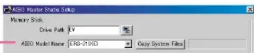
Select your AIBO model name.
An (E) model name means it does English voice-recognition.
4 Click Copy System Files.
The system files for the selected model will be overwritten on the "Memory Stick" in the specified drive.
5 Click OK
Setting up a wireless LAN environment
If you are using AIBO ERS-210/220, you can wirelessly transfer programs and data that you have created between AIBO and your PC by using AIBO wireless LAN card (sold separately).
Features available with wireless LAN environment
Wireless LAN makes the features listed below possible. You'll be able to make actions and behaviors more efficiently because you'll be able to test them in the process.
- Upload behavior programs
- Command AIBO to execute behaviors (You can trace a group box that is currently being executed.)
- Upload the action library
- Command AIBO to test-run actions and elements (motions, sounds, LED's)
Required equipment
Both your AIBO and PC need to support wireless LAN and be capable of wireless LAN communication.
The AIBO Master Studio software enables wireless communication between your PC and a single AIBO.
For AIBO
You will need both of the following:
• AIBO Wireless LAN Card
For instructions on installing the card in AIBO, please refer to the manual of the AIBO Wireless LAN Card.
- "Memory Stick"
Use the "Memory Stick" included in the AIBO package or an AIBO Programming Memory Stick (sold separately) to which the appropriate system files have been copied.
For the PC
You will need either of the following:
- A PC equipped with an IEEE802.11b-compatible wireless LAN card*
- PC connected to a wired LAN through an access point* compliant with the IEEE 802.11b standard
* Please use Sony recommended products.
When an access point is used

flowchart
graph TD
    A["Desktop Computer"] <--> B["Laptop"]
    C["Desktop Mouse"] <--> D["Laptop"]
    style A fill:#f9f,stroke:#333
    style B fill:#f9f,stroke:#333
    style C fill:#f9f,stroke:#333
    style D fill:#f9f,stroke:#333
    note right of A: "When an access point is not used"
    note right of D: "When an access point is not used"
Notes
The PC can be connected to the access point via wireless LAN or wired LAN (network cable).
• To connect the PC to the access point via wireless LAN, install an IEEE802.11b-compatible wireless LAN card on the PC.
• To connect the PC to the access point via wired LAN, you will need a hub and two network cables.
Wireless LAN information setup
Insert the AIBO wireless LAN card into your AIBO, and start the setup program.
Tip
You can set up a wireless LAN connection using a LAN by inserting a "Memory Stick" with the appropriate system files in AIBO and using a computer connected to the LAN. Please see the wireless LAN card operating manual for details.
Note
If you insert a "Memory Stick" and start AIBO while the AIBO wireless LAN card is pulled out, the network settings on the "Memory Stick" will return to default values.
You can proceed with set up in AIBO Master Studio Setup by inserting a "Memory Stick" into the "Memory Stick" drive.
1 Click the Start button in Windows and choose Programs - AIBO Master Studio - AIBO Master Studio Setup.
The AIBO Master Studio Setup dialog box appears.
2 Insert the "Memory Stick" with the appropriate system files into the drive.
3 Set up wireless LAN information.

①Check the Use AIBO Wireless LAN Card box.
②If you want to display "Memory Stick" information click [Import].
③Input the AIBO IP address (AIBO wireless LAN card).
④Input the Subnet Mask.
⑤Input the Default Gateway IP address. You may omit specifying an IP address, in which case the default gateway will not be used.
⑥Input the AIBO name (up to 8 alphanumerical characters) that will be used in the wireless zone.
⑦Input the wireless network name (up to 32 alphanumerical characters).
⑧Input the key characters to be used for encryption of wireless data (5 alphanumeric characters). If you don't want to use encryption, do not enter anything.
⑨Select the Action mode (wireless LAN topology).
⑩Select the wireless channel (when you use ad hoc mode).
⑪Input the user ID (up to 8 alphanumerical characters) to log on to the wireless network.
⑫Input password (up to 8 alphanumerical characters) to log on to the wireless network.
⑬Enter the same password you input in step ⑫ again to confirm it.
Tip
If you don't designate a user ID and password, anyone can access your AIBO wireless LAN connection without authentication, so we recommend that you set up a user ID and password.
4 Click [Export].
This saves the wireless LAN settings and makes wireless LAN functions available to AIBO Master Studio.
5 Click [OK] to close the window.
Tip
The wireless LAN setup information that is input last will also be stored on the PC, so you don't need to input information from the beginning every time you use a new "Memory Stick."
Execute Connection Test
If you insert the "Memory Stick" that you used to set up the wireless LAN into AIBO, boot AIBO, and click Test Connection, that will execute an AIBO connection test using the set wireless LAN information.
AIBO Master Studio
Chapter 3
Quick Behavior Arranger
How to use Quick Behavior Arranger.
Overview
Quick Behavior Arranger enables you to create two kinds of programs. It's a wizard, so even people who aren't familiar with the program can easily create AIBO programs.
The Tutorial Guide explains how to use Quick Behavior Arranger using examples.
- Sequential Execution Type
A behavior program describing a series of AIBO actions such as "stand up, move, and sit down."
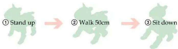
flowchart
graph LR
    A["① Stand up"] --> B["② Walk 50cm"]
    B --> C["③ Sit down"]
• Stimulus - Driven Execution Type
A behavior program that makes use of sensor inputs, voice recognition, and other functions.
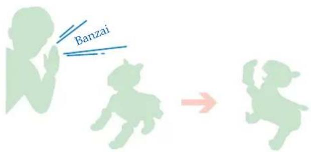
Fewer commands are available in Quick Behavior Arranger compared to Behavior Arranger, so use Behavior Arranger if you want to create complicated programs.
How to use original actions
You can add original actions in addition to system actions that are already prepared to behaviors. If you use original actions, use Action Composer first to save an action library onto a "Memory Stick." For details about Action Composer, see "Chapter 5 Action Composer" (page 71).
How to Create Behaviors
Start Quick Behavior Arranger, and create behavior programs by following the instructions on the screen.
1 Click the Start button in Windows and choose Programs - AIBO Master Studio - Quick Behavior Arranger.
A window to select the model appears.

2 Select your AIBO model name and click Next.
Select your AIBO model and click Next. A window to select the program type appears.
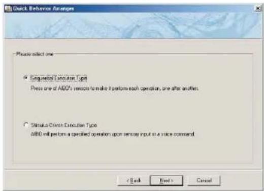
3 Select Behavior Program type and click Next.
Follow the instructions on the screen.
Note
You can use Behavior Arranger to edit programs created using Quick Behavior Arranger. If you open a program that you created in Behavior Arranger, it automatically places as many action boxes as there are action selection fields. If you don't input anything in an action selection field, the action box won't have any commands.
AIBO Master Studio
Chapter 4
Behavior Arranger
Procedures for using Behavior Arranger.
Overview
Behavior Arranger shows ABIO behaviors in a flowchart to create behavior programs. You can create anything from programs made of simple sequential actions such as “stand up and walk” to complicated programs using branching programs, and subroutines using conditions such as “when the head is touched, turn right.” You can use events that use sensor switches, as well as voice recognition words in English, and sounds (media link sounds and tonal scales), as conditions. You can quickly create behavior programs using built-in system actions in Behavior Arranger. If you want to use your own original actions, create actions using Action Composer and arrange them in Behavior Arranger to incorporate the actions in programs. For Action Composer details, see “Chapter 5 Action Composer” (page 71).
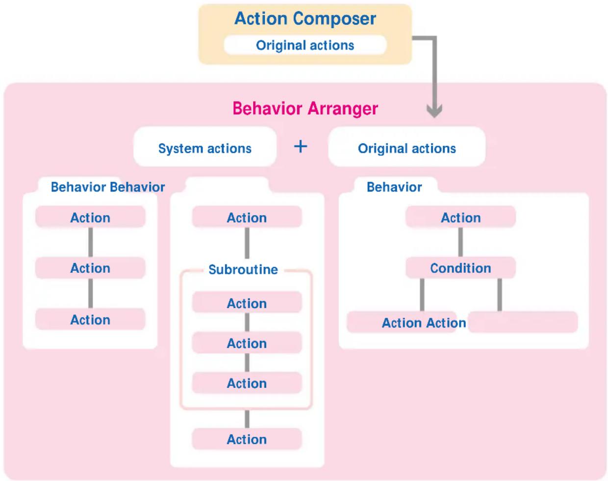
flowchart
graph TD
    A["Action Composer\nOriginal actions"] --> B["Behavior Arranger"]
    B --> C["System actions + Original actions"]
    C --> D["Behavior Behavior"]
    C --> E["Subroutine"]
    C --> F["Action"]
    D --> G["Action"]
    D --> H["Action"]
    E --> I["Action"]
    E --> J["Action"]
    F --> K["Action"]
    F --> L["Action"]
    G --> M["Action"]
    H --> N["Action"]
    I --> O["Action"]
    J --> P["Action"]
    K --> Q["Action"]
    L --> R["Action"]
    M --> S["Action"]
    N --> T["Action"]
    O --> U["Action"]
    P --> V["Action"]
    Q --> W["Action"]
    R --> X["Action"]
    S --> Y["Action"]
    T --> Z["Action"]
    U --> AA["Action"]
    V --> AB["Action"]
    W --> AC["Action"]
    X --> AD["Action"]
    Y --> AE["Action"]
    Z --> AF["Action"]
Main components of Behavior Arranger
In Behavior Arranger, program structures are expressed as flowcharts, making the programming process easier to understand. Choose from among the several boxes on the toolbar, drag them to the edit window, and connect them to create a flowchart.

flowchart
graph TD
    A["START"] --> B["Mark_DNY"]
    B --> C["Mark_DNY"]
    C --> D["NONE"]
    C --> E["NOR_DNY"]
    E --> F["Edit window"]
    style A fill:#f9f,stroke:#333
    style F fill:#ccf,stroke:#333
Mouse modes
In the edit window, operate the mouse by switching between the two modes.
Mouse: normal mode
Select this mode to place and move boxes in the edit window.
Mouse: link mode
Select this mode to connect boxes that have been placed in the edit window. When you drag from the terminal (round white dot) of one box to the box you want to connect, a line appears linking the two boxes.
Boxes
Input commands in boxes and connect the boxes with the mouse.
Action box
The box is used for designating commands such as AIBO actions other than branching conditions. Sequential commands can be designated in one box.
Commands in an action box are designated in the Action properties dialog box.
Action properties dialog box

Designate sequential commands in one box.
PLAY, STOP, QUIT, ADD and SUB are examples of action box commands.
Example:
| Main Sub Name Horizontal Distance |
PLAY ACTION WALK 20 100
The example above commands AIBO to walk for about 100 mm at an angle of 20^ to the left. (For the horizontal angle, + indicates an angle to the left and – indicates an angle to the right. The actual distance AIBO walks will depend on the condition of the floor.)
Branch box
This box is for designating a branch in the program.
Branch conditions in a branch box are designated in the Branch properties dialog box.
Branch properties dialog box

Designate conditions and jump destinations.
IF, AND, OR and ELSE are examples of branch commands.
Example:
| Type Variable Op Value Jump to |
IF DISTANCE < 200 LeftTurn
ELSE
MoveForward
In the example above, if the distance to an obstacle is less than 200mm, the program jumps to the box named LeftTurn, and in all other cases jumps to the box named MoveForward.
Group box
A box containing subroutine (grouped programs). The subroutine called by a group box is designated in the Group properties dialog box.
Groups form levels. In Behavior Arranger, due to programming limitations, an upper-level group can activate a lower-level group but not vice-versa. (When group A activates group B, group A is at a higher level than group B.)
Group properties dialog box
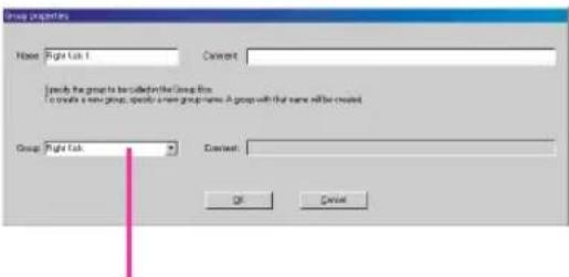
Choose a subroutine (group).
A group at the highest level is a Main group.
Saved behavior programs (.be) can be used as subroutines in other programs.
It is very convenient if you create programs to be used as subroutines beforehand, and add them to the Behavior Library Folder (\AIBO Master Studio\BA\Library) in AIBO Master Studio. Click library box 📄 to select subroutines.
Terminal box
The terminal box indicates the beginning or end of a program or a subroutine. The START box and END box in the Main group that are displayed when you first start making a program or subroutine are also terminal boxes. Designate the name of a terminal box in Terminal properties.
Terminal properties dialog box
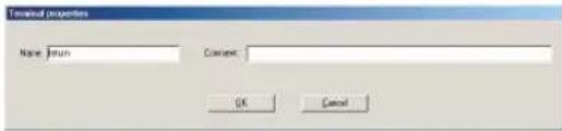
Creating and Editing Behaviors
Create behavior programs either by starting Behavior Arranger and creating new programs, or by editing programs that you already have. This section explains how to create a new behavior program.
Start
1 Click the Start button in Windows and choose Programs - AIBO Master Studio and click Behavior Arranger.
Behavior Arranger will start.
![War - Behavior Analyzer Command: to operate on current program [190-2013]](/content/2026/06/1199127/images/3914e32cb63a9ae88fe1af00d7620f1c397fbd724bf4f666ce2aaf3fc0be68cd.jpg)
For an explanation of Behavior Arranger names and functions, see "Behavior Arranger" in "Chapter 6 Reference" (page 108).
2 From the menu, choose File-New.
The Select model dialog box appears.
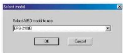
3 Select your AIBO model
Select your AIBO model name, and click OK.
START Box and END Box appear in the Edit window.
![Toolbar Enter Behavior Analyzer File Edit View Insert Group Help START (ND) Creates a new program [EPS-2016]](/content/2026/06/1199127/images/343caeb5b7f24a6d1c757d09273588526d77a7ea3898654a35d4e106accdabf1.jpg)
Edit window
Tip
If you want to edit a program that you already have, select File-Open from the menu to load the file that you want to edit. Programs that you created using previous versions of AIBO Master Studio will be loaded as AIBO ERS-210 programs.
Arranging Boxes
Position boxes in which to designate commands in the edit window.
1 Select a box
Click the Box button on the toolbar or select Box from the Insert menu. A highlighted box appears.
Tip
You can also select Box from the context menu that appears by right-clicking on the edit window.
2 Position a box
Click the position you would like the box to move to in the edit window. The box's properties dialog box appears.
3 Input content for the box.
Input box commands in the properties dialog box. For details, see "Creating and Editing Boxes" (page 40).
You can change the contents of a box later, so you may create the overall flow of a program by allocating empty boxes, then input commands into those boxes.
4 Close properties dialog box
Click OK in the properties dialog box. Box will be positioned in the edit window.

5 Allocate as many boxes as you need
Repeat steps 1 to 4 to position as many boxes as you need.
Note
You can use around 10,000 boxes in Behavior Arranger. However, since AIBO main memory is shared with the Action Library and AIBO system files, the number of boxes and commands that can be used in Behavior Arranger will be reduced if memory-intensive actions are used.
How to move boxes
Put the mouse in normal mode and drag the box that you want to move.
How to delete boxes
Select the box that you want to delete and press the Delete key. You can also delete by right-clicking on a box and selecting Delete Box from the context menu.
Connect Boxes
Once you position boxes in the edit window, connect box terminals to associate them with each other.
A round dot on the top of a box is an input terminal, and a round dot at the bottom of a box is an output terminal.
1 Put the mouse in link mode
Click on the Toolbar.
2 Drag from the source box to the destination box
A white line will appear between the boxes, and the output terminal of the source and the input terminal of the destination box will be connected.

flowchart
graph TD
    A["Start"] --> B["Box01"]
    B --> C["END"]
3 Connect the rest of the boxes
Repeat the dragging process to connect all of the boxes.
How to connect branch boxes
Connect branch boxes by designating the branching conditions. Determine subsequent processes according to conditions such as “with the word ‘hello,’ shift process to movement A,” or “stop if approaching an obstacle.”
As many output terminals as branching conditions designated in the Branch properties dialog box will be set up. If you place the mouse cursor on an output terminal, the conditional expression will be displayed. If you drag from any output terminal to a destination box, corresponding conditional expressions and subsequent processes will be connected.
You can also connect a branch box and destination box by dragging without having to first set up the Branch properties dialog box of a branch box. In this case, you need to designate one or more branching conditions to branch to a destination box in the Condition dialog box that will appear as you drag.
Connecting group boxes with several output terminals
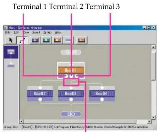
If there are several output terminal boxes in a group (subroutine), as many output terminals as terminal boxes will appear for a corresponding group box. If you place the mouse cursor on an output terminal, the corresponding terminal box name will appear, so check the box name, choose a terminal, and drag it to the destination box to connect it.
Disconnecting boxes
Select a line to disconnect and press the Delete key.
You can also use the following alternative methods.
- Use the Delete Connection context menu item that appears when you right-click a line.
- Right-click on the output terminal or the box, and choose Delete Connection from the context menu (if there are several connections, a selection menu will appear).
Note
If you delete a box, any connection lines from the box's output terminals will also be deleted at the same time.
Moving the connecting line
Set the mouse to normal mode, select the line you want to move and drag it to the new position.
Tip
- A straight connection line with no angles cannot be moved.
- Connection lines cannot be moved to overlap their own box.
- For a group box designated to a group with several terminals, you can rearrange the terminals to eliminate line crossovers. For details, see "Rearranging terminals." (page 49)
Save and Execute Behaviors
Save created behavior programs using a "Memory Stick" drive ("Memory Stick"
Reader/Writer) or using a wireless LAN, and execute them on AIBO.
Note
System files for different models cannot be saved to the same "Memory Stick."
Tip
Programs created in Behavior Arranger will be saved in \OPEN-R\APP\PC\AMS\R-CODE.R on a "Memory Stick."
When you use "Memory Stick" drive
1 Insert a "Memory Stick" with the appropriate system files into the drive.
2 While the behavior program is displayed in the edit window, from the menu select File - Save to Memory Stick.
When saving is completed, a confirmation message will appear.
3 Insert the "Memory Stick" into AIBO and boot AIBO.
When AIBO is booted, a behavior program will be automatically executed. If you want to execute it again, press the Pause button on AIBO to stop the movement, and reboot.
When you use a wireless LAN
1 Insert a "Memory Stick" with the appropriate system files into AIBO, and boot AIBO.
2 While the behavior program is displayed in the edit window, from the menu select File - Wireless LAN Connection.
Wireless LAN connection will appear and the computer connects to AIBO over the wireless LAN.
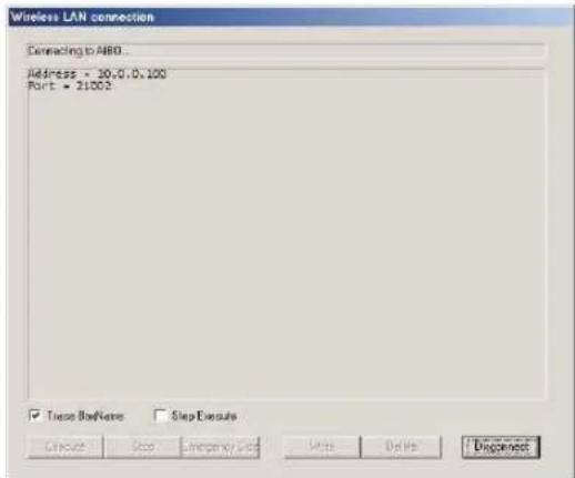
3 Click the function button that you want to use.
Execute
Transfers a behavior program to the "Memory Stick" inserted into AIBO and executes it.
Stop
Stops a process that is being executed by AIBO after the current action is completed.
Emergency Stop
Immediately stops a process that is being executed by AIBO including the current actions. AIBO will be unstable after an emergency stop, and if you select Execute again, AIBO will start “stretching.”
Write
Transfers the behavior program to the "Memory Stick" inserted in AIBO without executing it. (The same as selecting the File-Save to Memory Stick from the menu.)
Delete
Deletes the behavior program from the "Memory Stick" inserted in AIBO.
Check Box
Trace Box Name
Displays the group and box name of a program that is being executed in AIBO. This is convenient to see if there are errors in the program.
Step Execute
If this is checked, execution pauses every time an action completes in the program. To continue, click the Execute button again. This is convenient to see if there are errors in the program. If this isn't checked, clicking the Execute button will play the program from the beginning.
4 If the program execution is complete, click Disconnect.
The wireless LAN connection will be disconnected, and the dialog box will close.
Creating and Editing Boxes
Create or edit boxes, and specify program commands. Please see "Command Reference" (page 52) for available command details.
Action box
When you place an action box in the edit window or double-click on an existing box, the Action properties dialog box is displayed. Sequential commands (other than branching) can be designated in one box.
![4 Add Click this button to add to the list a command specified in the combo box. 1 Name Input the box name. 2 Comment Type in your comments about the box (optional). 3 Combo box Specify commands and parameters starting with the Main command. The number of parameters and boxes you need to specify are determined by the command. Column with * Discretionary input is available. Column with # Numerical input is available. Comment: type in comments about the command (optional) Modify Reflects changes made in the combo box to the list. Delete Deletes the selected line from the list. [Up] [Down] Moves the selected line up or down the list. 5 OK Closes the dialog box. Cancel Cancels a new box or an operation in the Action Properties dialog box. Auto Modify If you check this, changes in the Combo box will automatically reflect the selected command.](/content/2026/06/1199127/images/8be91679967594c6cb4ea8245e1468c71359b8039008e696133c1abc6186aaf2.jpg)
To edit a command in the list
①Select a command from the list.
②To change, add changes to the command in the combo box and click Modify.
To delete, click Delete.
To change the list order, click [Up] [Down] and move the line up or down the list.
Branch box
When you place a branch box in the edit window or double-click on an existing box, the Branch properties dialog box is displayed. Branch conditions are designated in this box.
![4 Add Click this button to add to the list a condition specified in the combo box. 1 Name Input the box name. 2 Comment Type in your comments about the box (optional). 3 Combo box Enter branch conditions. Type: Branch condition Variable: First operand Op: Comparison operator Value: Second operand Jump To: The box to jump to when a condition is met Comment: Comments about the command (optional) Modify Reflects changes made in the combo box to the list. Delete Deletes the selected line from the list. [Up] [Down] Moves the selected line up or down the list. 5 OK Closes the dialog box. 5.0 Auto Modify If you check this, changes in the Combo box will automatically reflect the selected command. Cancel Cancels a new box or an operation in the Branch Properties dialog box.](/content/2026/06/1199127/images/0cde88d3b799fd8b7e26e43953043a9e1ca050dc3192d6fed3c2e4d30d93739d.jpg)
To edit a command in the list
①Select a command from the list.
②To change, add changes to the condition in the combo box and click Modify.
To delete, click Delete.
To change the list order, click [Up] [Down] and move the line up or down the list.
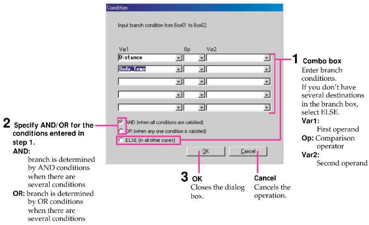
Condition dialog box
You can designate branch conditions for a branch box in dialog boxes other than the Branch properties dialog box.
Put the mouse in link mode, and designate conditions in the Condition dialog box that appears when you drag from the branch box to the action box to jump to.
Group box
When you place a group box in the edit window or double-click on a group box without a designated group, the Group properties dialog box is displayed.
Specify the group (subroutine) to activate in this box.
If a group is already specified, right-click on the box and select Properties from the menu to display it.

Note
A group box and a group are different. A group box is something that activates a group, and a group is a subroutine entity. Even if you delete a group box, the group won't be deleted. In the same manner, even if you delete a group, the group box won't be deleted.
How to designate a library to a group box
If you save a behavior program, you can use the behavior program as a subroutine when making another program. A group of these programs (.be) is called a (behavior) library. AIBO Master Studio provides several libraries in the AIBO Master Studio\BA\Library folder for your use.
When you place a library box in the edit window, the Open dialog box is displayed. Specify the program to be activated by the library box.

A group box will be placed in the edit window (a library box is a kind of group box). When you right-click on the box and choose Properties from the context menu, a Group properties dialog box is displayed.

Note
If actions other than system actions (i.e. actions made with Action Composer) are used in the behavior library, you need to save an action library that include the actions to a "Memory Stick" in advance using Action Composer.
Terminal box
When you place a terminal box in the edit window or double-click a terminal box, the Terminal properties dialog box is displayed. Enter the terminal box name and comments in this box.
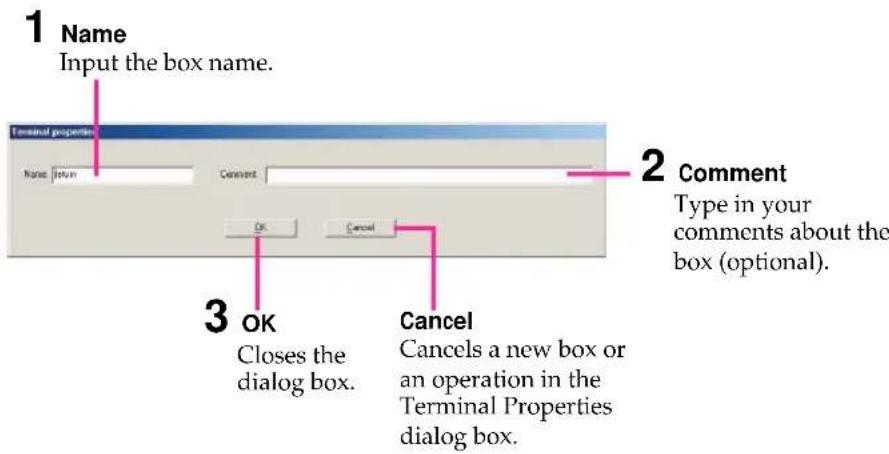
At the end of subroutine, input a box name such as RETURN to indicate that the process will return to the main program. Terminal box names can be entered freely, for example, QUIT, END and RETURN.
Using Groups
Making a group
Follow the procedure below to make a group (subroutine) that will be activated by a group box.
When You Create Subroutines
1 From the menu, select Group-Create New Group.
A Group dialog box appears.
2 Define the group.

3 Close the dialog box.
Click OK in the Group dialog box. An edit window opens for the new group.
4 Create a behavior program (in the same manner as for a main group).
5 From the menu, select File - Close this Window.
It returns to the edit window of the program that activates the created group (subroutine).
Note
Even if you close the edit window for a group, the group isn't deleted.
6 Place a group box, and designate a group name used in the Group combo box of the Group properties dialog box.

Select a group name that you've made as the group to activate.
For details, see "Group Box" (page 43).
When You Create a group (Subroutine) from a Group Box
1 Position the group box in the edit window, and input the name of the group in the Group properties dialog box.

Input the group name to be created.
A group will be created and an edit window for the group opens. The group box to activate the created group will be placed in the original edit window.
2 Create a behavior program (in the same manner as for a main group).
3 From the menu, select File-Close this Window.
Tip
Even if you close the edit window for a group, the group isn't deleted.
Moving from group to group
If a group includes a child group (subroutine), you can move it from one group to another by using the history bar, and see a history of moves between groups.

flowchart
graph TD
    A["Box01"] --> B["1"]
    A --> C["2"]
    A --> D["3"]
    B --> E["Output"]
    C --> E
    D --> E
History bar
You can move a group box that you want to edit to a child group (subroutine) by double-clicking it, and the program will appear in the edit window. Such moves between groups will appear in the history bar. The main group always appears on top, and the history will be updated as you create child groups (subroutines).
Groups displayed in the history bar can be accessed by clicking on one of the boxes displayed in the bar.
Note
When you access a different subgroup from the same group, a different trace is displayed in the history bar.
Key operation
Home Moves to the Main group.
End Moves to the group indicated at the bottom of the history bar.
Page Up Moves to the group directly above in the history bar.
Page Down Moves to the group directly below in the history bar.
Mouse operation
Left double-click Opens the chosen group in the edit window.
Place the mouse Displays the group name. pointer over a box in the history bar
Rearranging terminals
If a group that has several output terminal boxes is activated from a group box, you can rearrange the terminals to keep the connection lines from crossing.
1 In the group box, place the mouse pointer over the terminals to check the names of the terminals you want to rearrange.
flowchart
graph TD
    A["Start"] --> B["Box01"]
    B --> C["Box02"]
    B --> D["Box03"]
    B --> E["Box04"]
    C --> F["END"]
    D --> F
    E --> F
Crossed
2 Double-click the group box.
The program defined by the group box is displayed.
3 Choose Group - Set Order of Terminals.
The Terminal list is displayed.

4 Choose a line and click [Up] [Down] to change the terminal order.
In the case of a Step 1 screen, change the order to [1] [3] [2].
5 When you've rearranged the order, click Set order.
When you return to the group box, you'll find the terminals arranged in the new order and the crossed lines will have disappeared.
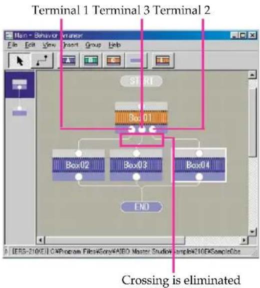
flowchart
graph TD
    A["Terminal 1"] --> B["Box 01"]
    C["Terminal 2"] --> D["Box 02"]
    E["Terminal 3"] --> F["Box 03"]
    G["Ending"] --> H["Box 04"]
    I["Crossing is eliminated"] --> J["End"]
How to Use Created Actions
To include actions other than system actions – i.e. actions using original motions, sounds, and LED flashing patterns – in a behavior program, follow the procedure below.
1 In Action Composer, create an action library that includes the action you want to use and save it to the “Memory Stick” (page 81).
A copy of the action library is also made in the hard disk, allowing you to refer to the action library from Behavior Arranger.
Note
Behavior Arranger refers to the action library saved last. If you are using several "Memory Sticks," make sure the action library in the "Memory Stick" you are using matches the one on the hard disk.
2 In Behavior Arranger, specify the action that you have created as a command in an Action box.
Specify [PLAY] for Main and [ACTION+] for Sub. Actions in the library that you saved in step 1 will appear in the Name combo box.
Select ACTION+

List of actions saved in Action Composer
Tips
You will be able to use the saved actions after saving an action library to the "Memory Stick" in Action Composer by opening the Action properties dialog box.
Notes
You can use only one action library at a time. To use a new action while making a behavior program, first add the action to the action library you've saved.
Printing Behaviors
You can print a flowchart of behavior programs that you have created. Please set up the page before printing.
Page Setup
1 From the menu, select File - Page Setup.
The Page Setup dialog box appears.
Tip
You can change the printer you want to use by clicking Printer.
2 Set Paper, Orientation, and Margins.
3 Click OK.
1 From the menu, select File - Print.
The Print dialog box appears.
2 Set the Print, Print range, and Number of copies to be printed.
Tip
When the main group of a behavior program has a child group (subroutine), you can print flowcharts of the main group and child groups by choosing All groups.

3 Click OK.
A flowchart of the behavior program that is displayed in the edit window will be printed.
Command Reference
You can refer to Behavior Arranger commands in this manual as well as the Help system. Click the Start button in Windows, choose Programs -AIBO Master Studio- Command Reference, or select the Help menu from within Behavior Arranger, then Command Reference.
Action box commands
Action playback commands (Play-Action)
This section shows a list of names for built-in system actions (commands are listed alphabetically). These commands can be used when “Play” is chosen in Main and “Action” is chosen in Sub.
For overwrite execution, see "Programming precautions" (page 55).
Tips
Main [Play] - Sub [Action+] displays actions that were saved in Action Composer.
Overwrite execution
CHGPOS.STATR.NORMAL

Hangs head sorrowfully and lies down on the floor.
CHGPOS.WALK.NORMAL

Changes to walking position.
CONTACT.FRONT.HEAD

Heads the ball
CONTACT.FRONT.HEADL

Heads the ball to the left.
CONTACT.FRONT.HEADR

Heads the ball to the right.
CONTACT.RIGHT.TOUCH

Sits and with the right paw touches an object at the specified distance.
Horizontal angle 0 to 80 Unit: °
Distance Distance from AIBO Unit: mm
Overwrite execution
Crouches and with the right paw touches an object at the specified distance.
Horizontal angle 0 to 80 Unit: °
Distance Distance from AIBO Unit: mm
KICK

Kicks the specified position.
Horizontal angle -30 to 30 Unit:°
Distance Distance from AIBO Unit: mm
LIE

Lies down in the normal posture.
MOVE\_HEAD

Looks in the specified direction.
Alias for MOVE.HEAD.NORMAL.
Horizontal angle -60 to 60 Unit:°
Vertical angle -60 to 20 Unit: °
MOVE.HEAD.FAST

Looks quickly in the specified direction.
Horizontal angle -60 to 60 Unit: °
Vertical angle -60 to 20 Unit:°
MOVE.HEAD.NORMAL

Looks in the specified direction.
Horizontal angle -60 to 60 Unit: °
Vertical angle -60 to 20 Unit:°
MOVE.HEAD.SLOW

Looks slowly in the specified direction.
Horizontal angle -60 to 60 Unit: °
Vertical angle -60 to 20 Unit: °
| Overwrite execution | |
| MOVE.MOVE.NORMAL | OK |
| Walks to the designated position. Horizontal angle -180 to 180 Unit:° Distance 0 to 10,000 Unit: mm | |
| MOVE.MOVE.SLOW | OK |
| Walks slowly to the specified position. Horizontal angle -180 to 180 Unit:° Distance 0 to 10,000 Unit: mm | |
| MOVE.MOVE.SM ALL | OK |
| Walks taking small steps to the specified position. Horizontal angle -180 to 180 Unit:° Distance 0 to 10,000 Unit: mm | |
| MOVE.TURN.NORMAL | OK |
| Turns around to face the specified direction. Horizontal angle -180 to 180 Unit:° (+: counter-clockwise, -: clockwise) | |
| MOVE.TURN.SLOW | OK |
| Turns around slowly to face the specified direction. Horizontal angle -180 to 180 Unit:° (+: counter-clockwise, -: clockwise) | |
| PALONE.AUTO.EAR (ERS-210 only) Moves both ears. | OK |
| PALONE.AUTO.EARL (ERS-210 only) Moves the left ear. | OK |
| PALONE.AUTO.EARR (ERS-210 only) Moves the right ear. | OK |
| PALONE.AUTO.EARSTOP (ERS-210 only) Stops moving ears. | OK |
| PALONE.AUTO.TAILD (ERS-210 only) Lowers tail. | OK |
| Overwrite execution | |
| PALONE.AUTO.TAILH (ERS-210 only)Wags tail left to right. | OK |
| PALONE.AUTO.TAILROT (ERS-210 only)Rotates tail. | OK |
| PALONE.AUTO.TAILSTOP (ERS-210 only)Stops moving tail. | OK |
| PALONE.AUTO.TAILUP (ERS-210 only)Raises tail. | OK |
| PALONE.AUTO.TAILV (ERS-210 only)Wags tail up and down. | OK |
| SEARCH | OK |
| Searches for an object starting from the current direction. | |
| Alias for SEARCH.HEAD.NORMAL. | |
| Object Pink ball (included in AIBO unit) | |
| SEARCH.HEAD.LowCENT | OK |
| Looks down and searches for an object. | |
| Object Pink Ball (included in AIBO unit) | |
| SEARCH.HEAD.NORMAL | OK |
| Looks in the current direction to search for an object | |
| Object Pink Ball (included in AIBO unit) | |
| SEARCH.HEAD.NORM ALCENT | OK |
| Looks in front and searches for an object.Object Pink Ball (included in AIBO unit) |
| SEARCH.HEAD.SLOW | OK |
| Looks in the current direction to search slowly for a object. | |
| Object Pink Ball (included in AIBO unit) | |
| SEARCH.HEAD.SLOWCENT | OK |
| Looks in front and searches slowly for an object.Object Pink Ball (included in AIBO unit) | |
| Overwrite execution | |
SIT
Sits.

SM ESS.ERROR.ERROR1
Error notice 1 for debugging.
ERS-210: Flashes the mode indicator, the left eye lights (three) and the tail light.
ERS-220: Turns on both the right and left face side lights in blue, and the mode indicator.
ERS-310 series:
Quickly flashes the horn light alternately in blue/orange, and turns on the mode indicator.
SM ESS.ERROR.ERROR2

Error notice 2 for debugging.
ERS-210: Flashes the mode indicator, the right eye lights (three) and the tail light.
ERS-220: Flashes both the right and left face side lights in blue, and the mode indicator.
ERS-310 series:
Slowly flashes the horn light alternately in blue/orange, and turns on the mode indicator.
SM ESS.NOTICE.NOTICE1

Notice 1 for debugging.
ERS-210: Turn on the mode indicator, the eye lights (all), and the tail light.
ERS-220: Flashes the left face side light in blue.
ERS-310 series:
Slowly flashes the horn light in orange, and turns on the mode indicator.
| Overwrite execution |
SM ESS.NOTICE.NOTICE2

Notice 2 for debugging.
ERS-210: Turn on the mode indicator, the eye lights (all), and the tail light.
ERS-220: Flashes the right face side light in blue.
ERS-310 series:
Slowly flashes the horn light in orange, and turns on the mode indicator.
SM ESS.MODE.CLEAR

Clears debugging display.
STAND

Stands.
STOP\_WALK

Stops walking.
TOUCH

Sits down and touches an object at the specified position with right front leg.
Alias for CONTACT.RIGHT.TOUCH.
Horizontal angle 0 to 80 Unit:°
Distance Distance from AIBO Unit: mm
TRACK\_HEAD

Tracks the object in sight. (AIBO won't look for it if it loses it.)
Object Pink Ball (included in AIBO unit)
TURN

Alias for MOVE.TURN.NORMAL.
Horizontal angle -180 to 180 Unit:°
(+: counter-clockwise, -: clockwise)
WALK

Alias for MOVE.MOVE.NORMAL.
Horizontal angle -180 to 180 Unit:°
Distance 0 to 10,000 Unit: mm
Programming precautions
- Command Completion
Since action commands (PLAY) such as "walk" and "shake head left and right" take time from execution to completion of the action, AIBO returns a completion notice when the action is completed. If you create a program that executes action commands after a completion notice is received, Individual actions can be steadily executed in sequence.
• Overwriting command execution
AIBO can execute several commands at the same time, such as “while walking, flash LED and play sound.” However, simultaneous execution of several commands is possible only if resources that the commands use (such as body parts, LEDs, and sounds) don’t overlap. For example, if you designate a command to turn off a LED after a command to turn on the same LED, only the last command will be executed and the LED will be turned off. If you designate a command to raise the right leg and a command to lower the same leg before the first action completes, AIBO will lower the right leg in the middle of raising it. Such overlaps are called overwriting command execution.
Overwriting command execution doesn't apply to all action commands, so see explanation of each individual command to see if overwriting execution is possible.
Commands that use variables
The commands in this section execute arithmetic operations using variables.
Restrictions on variables
Observe the following restrictions when using variables.
- Variable names cannot be longer than 32 characters.
- Use only alphanumeric characters and underscores in variable names.
- A variable name consisting only of capital letters cannot be used.
- A value must be a 16-bit integer, between -32,768 and +32,767.
SET
Assigns a value to the variable.
CLR
Clears a sensor variable.
ADD
Addition
$$ [ \text { Variable } ^ {} ] = [ \text { Variable } ^ {} ] + [ \text { Var / Value } ^ {*} ] $$
SUB
Subtraction
$$ [ \text { Variable } ^ {} ] = [ \text { Variable } ^ {} ] - [ \text { Var / Value } ^ {*} ] $$
MUL
Multiplication
$$ [ \text { Variable } ^ {} ] = [ \text { Variable } ^ {} ] \cdot [ \text { Var / Value } ^ {*} ] $$
DIV
Division
$$ [ \text { Variable } ^ {} ] = [ \text { Variable } ^ {} ] \div [ \text { Var / Value } ^ {*} ] $$
MOD
Remainder
$$ [ \text {Variable} ^ {} ] = [ \text {Variable} ^ {} ] \% [ \text {Var} / \text {Value} ^ {*} ] $$
IOR
Logical OR (logical OR per bit)
[Variable*] | [Var/Value*]
XOR
Exclusive OR (exclusive OR per bit)
[Variable*] ^ [Val/Value*]
RND
Random number
Generates a random number from a specified range of [From#] to [To#].
Variable* The random number generated
From#/To# Range of the random number
VSAVE
Saves the value of a variable. Saves the value of a variable in a file in a "Memory Stick."
The name of the file to be saved is
\OPEN-R\APP\PC\AMS\
Note
Up to 8-character variable names can be saved due to file system restrictions.
VLOAD
Loads the value of a variable from a file in a
"Memory Stick."
The name of the file to be loaded is
\OPEN-R\APP\PC\AMS\
Note
Up to 8-character variable names can be saved due to file system restrictions.
VDUMP
Displays the variable (when executing with a wireless LAN).
Other commands
STOP
Stops AIBO.
If an action is being played back, AIBO is stopped after the action is completed.
QUIT
Stops AIBO immediately.
AIBO is stopped even in mid-action.
WAIT
Waits for the current action to end and confirms completion before executing the command that follows the WAIT command.
Variables
The following variables can be used in action boxes and branch boxes in addition to user variables.
Common to all models
Using the AIBO internal clock
Year
Year Effective range: 2000 or later
Month
Month
Day
Day
Hour
Hour (24-hour system)
Min
Minutes
Sec
Seconds (resolution: 2 seconds)
Dow
Day of the week (Sunday = 0, Monday = 1, ..., Saturday = 6)
Other variables
Status
Detects if it has fallen or is in normal state. When AIBO falls down, the variable is set to "1." To clear the variable, use the SET command to enter "0." (When AIBO falls down, it gets up automatically and the program is executed again from the beginning.)
Wait
The length of time set for the Wait command Unit: ms
Brightness
Brightness of the surroundings (0 - 255) Darker with smaller numbers, brighter with larger numbers.
Pink\_Ball
When the pink ball is detected, the variable is set to "1." To clear the variable, use the SET command to enter "0."
Pink\_Ball\_H
Horizontal angle of the pink ball Unit:°
Pink\_Ball\_V
Vertical angle of the pink ball Unit:°
Pink\_Ball\_D
Distance to the pink ball Unit: mm
AU\_AiboSound
Used for AIBO-ware with media link mode capability.
When an AIBO sound such as a media link sound is detected, the variable is set to "1."
To clear the variable, use the SET command to enter "0."
AU\_AiboSound\_ID
Tone ID of an AIBO sound such as a media link sound. (See "Media link sound that can be used for sound recognition"
AU\_AiboTone
When a command tonal scale used for AIBO ERS-110/111 is detected, the variable is set to "1."
To clear the variable, use the SET command to enter "0."
AU\_AiboTone\_ID
Tonal scale ID used for AIBO ERS-110/111.
(See "Tonal scales that can be used for sound recognition"
AU\_Voice
When a word is detected using voice recognition, the variable is set to "1."
To clear the variable, use the SET command to enter "0."
AU\_Voice\_ID
ID of a word detected using voice recognition.
(See "Words that can be used for voice recognition"
Batt\_Rest
Remaining AIBO battery power Unit: %
Batt\_Temp
AIBO battery temperature Unit: °C
Body\_Temp
AIBO Temperature Unit: °C
Distance
Distance from the obstacle sensor to an obstacle.
If there are no obstacles, "900" will return.
Effective range: 0 - 600 Unit: mm
Words that can be used for voice recognition
The following voice recognition terms can be used as AU_Voice_ID variables. What action AIBO should take in response to a word input can be freely determined.
ID When to use (example)
| 1 AIBO Talk to AIBO | |
| 2 What's your name?Ask its name (Use an action with a WAV file in which the name is recorded). | |
| 3 Say hello Ask to say hello | |
| 4 Shake paw Ask to shake a paw | |
| 5 Morning Morning greeting | |
| 6 Hello Daytime greeting | |
| 7 Good night Night greeting | |
| 8 See you Part with AIBO | |
| 9 How are you? Ask how AIBO is doing | |
| 10 Hey AIBO Talk to AIBO | |
| 11 Thanks Express gratitude | |
| 12 Sorry Apologize | |
| 13 Cheer up Cheer up | |
| 14 Banzai Play together | |
| 15 That's right Tell AIBO something is right | |
| 16 That's wrong Tell AIBO something is wrong | |
| 17 Good AIBO Praise | |
| 18 Stop it Scold | |
| 19 Let's play! Ask AIBO to play. | |
| 20 Sing a song Make AIBO sing a song. | |
| 21 Dance Ask AIBO to dance |
| 22 Show time | Ask AIBO to perform |
| 23 Pose for me | Ask for a special pause |
| 24 Clown around | Ask AIBO to do something silly |
| 25 Show off | Ask AIBO to do something it is good at |
| 26 Say message | Make AIBO say something |
| 27 Let's be secret | Tell a secret story |
| 28 Open sesame | Break a spell with a magic word |
| 29 Happy day | Tell a funny thing |
| 30 Stand up Make AIBO stand up | |
| 31 Lie down | Make AIBO lie down |
| 32 Sit down Make AIBO sit down | |
| 33 Turn right | Make AIBO turn or move right |
| 34 Turn left Make AIBO turn or move left | |
| 35 Go forward | Make AIBO go forward |
| 36 Go backward | Make AIBO back off |
| 37 Go ahead Make AIBO start doing something | |
| 38 Stop | Make AIBO stop doing something |
| 39 Faster | Make AIBO do something faster |
| 40 Slow down Make AIBO do something slower | |
| 41 Pink ball | Make AIBO respond to the pink ball |
| 42 Right leg kick | Make AIBO kick the pink ball with its right hind leg |
| 43 Right leg touch Make AIBO touch the pink ball with its right foreleg | |
| 44 Left leg kick Make AIBO kick the pink ball with its left hind leg | |
| 45 Left leg touch Make AIBO touch the pink ball with its left foreleg | |
| 46 Ready set go Make AIBO start competing | |
| 47 You won Tell AIBO that it won | |
| 48 You lost Tell AIBO that it lost | |
| 49 Action one Free use | |
| 50 Action two Free use | |
| 51 Action three Free use | |
| 52 Action four Free use | |
| 53 Action five Free use | |
Media link sounds that can be used for sound recognition
AIBO-ware “AIBO Pal (ERF-310AW07E)” for AIBO ERS-310 series is equipped with a “Media link mode” that enables AIBO to communicate with media by responding to specific sound signals from media such as television and video. AIBO Master Studio version 1.1 can create programs to detect such media link sounds.
The following media link sound can be used for variable AU_AiboSound_ID. (There are sound files in the installed Sample\AiboSound folder.) Media link sounds include explanations of how AIBO ERS-310 series with AIBO Pal installed will react, but the actions AIBO should take in response to media link sounds can be freely determined.
Note
For details of media link mode, see the operating manual attach to the individual product.
ID File name Reaction of AIBO ERS-310 series with AIBO Pal (ERF-310AW07E) installed
| 1 AS_Start_AC If you have two AIBOERS-310 series units withAIBO Pal installed, andthey hear this melody,they will begincommunication betweeneach other. (Same asletting AIBO recognizethe word “Talk to yourfriend.”) | |
| 2 AS02_Start_ML1 | Starts media link mode.(Same as letting itrecognize the phrases“Media link mode.”) |
| 3 AS03_Start_ML2 | |
| 4 AS04_Start_ML3 | |
| 5 AS05_End_ML Ends media link mode,and returns toautonomous mode. (Sameas letting AIBO recognizethe word “That’s it.”) | |
| 6 AS06_Hello Raises a front paw ingreeting. | |
| 7 AS07_Bye Waves a front paw to saygoodbye. | |
| 8 AS08_Sleep Lies on its stomach andpretends to sleep. | |
| 9 AS09_Nod_Short Gives a short nod. | |
| 10 AS10_Nod_Long Gives a long nod. | |
| 11 AS11_Expect Shows great expectation. | |
| 12 AS12_Yes Responds positively. | |
| 13 AS13_No Responds negatively. | |
| 14 AS14_Question Responds questioningly. | |
| 15 AS15_Joy Pose of joy. | |
| 16 AS16_Happy Pose of great joy. | |
| 17 AS17_Disgust Pose of reluctance. | |
| 18 AS18_Surprise Pose of surprise. | |
| 19 AS19_Sad | Pose of sadness. |
| 20 AS20_Relief | Pose of relieved look. |
| 21 AS21_Appeal | Requests and desires. |
| 22 AS22_Action Performs various characteristic actions. | |
| 23 AS23_Dance | Dances. |
| 24 AS24_Song1 | Sings. |
| 25 AS25_Song2 | |
| 26 AS26_Fav_Dance Performs favorite dance. | |
| 27 AS27_Fear Pose of fear. | |
| 28 AS28_Greet | Bows. |
| 29 AS29_Pose | Poses for photo opportunity. |
| 30 AS30_Cheer | Raises both front paws. |
| 31 AS31_Look | Pose of caution. |
| 32 AS32_Abash | Pose of shyness. |
| 33 AS33_Charm Acts charmingly. | |
| 34 AS34_Type_CheckTells you its characteristic type. (Same as letting AIBO recognize the word “Do you feel okay?”) | |
| 35 AS35_Call | Notices incoming call. |
Tonal scales that can be used for sound recognition
Using AIBO's perfect pitch, you can utilize tonal scales as AIBO ERS110/111 commands. AIBO Master Studio version 1.1 can create programs to detect such tonal scales. The following tonal scales can be used for the variable AU_AiboTone_ID. (Use sounds in the installed Sample \AiboTone folder and AIBO ERS-110/111 sound commander for input.) What action AIBO should take in response to tonal scales can be freely determined.
*ID 1 – 34 are command type A, and 35 – 68 are command type B.
| ID | Tonal Sound Scale file | ID Tonal Sound scale file controller | Button in the ERS-110/111 | sound Settings of AIBO with AIBO ERS-110/111* | ||||
| Command S number method | Short scale Me hod | |||||||
| 1 | C5 D5 E5 | AT01.mid | 35 | C6 D6 E6 | AT35.mid | 00→SEND | CDE | Set AIBO to the autonomous mode |
| 2 | C5 E5 D5 | AT02.mid | 36 | C6 E6 D6 | AT36.mid | 01→SEND | CED | Set AIBO to the game mode |
| 3 | E5 C5 D5 | AT03.mid | 37 | E6 C6 D6 | AT37.mid | 02→SEND | ECD | Set AIBO to the performance mode |
| 4 | E5 D5 C5 | AT04.mid | 38 | E6 D6 C6 | AT38.mid | 03→SEND | EDC | Set AIBO to the “charging posture” |
| 5 | G5 C5 D5 | AT05.mid | 39 | G6 C6 D6 | AT39.mid | 81→SEND | GCD | Set AIBO to the command type A |
| 6 | G5 D5 C5 | AT06.mid | 40 | G6 D6 C6 | AT40.mid | 83→SEND | GDC | Set AIBO to the command type B |
| 7 | C5 G5 D5 | AT07.mid | 41 | C6 G6 D5 | AT41.mid | 84→SEND | CGD | Lower the volume one level |
| 8 | C5 D5 G5 | AT08.mid | 42 | C6 D6 G6 | AT42.mid | 86→SEND | CDG | Raise the volume one level |
| 9 | D5 E5 C5 | AT09.mid | 43 | D6 E6 C6 | AT43.mid | 88→SEND | DEC | Set AIBO to the sleep8 mode |
| 10 | D5 C5 E5 | AT10.mid | 44 | D6 C6 E6 | AT44.mid | 89→SEND | DCE | Set AIBO to the sleep mode |
*ID 1 – 34 are command type A, and 35 – 68 are command type B.
| ID | Tonal Sound Scale file | D Tonal Sound scale file controller | Button in the ERS-110/111 | sound Settings of AIBO with AIBO ERS-110/111* | ||||
| Command S number method | aning of tonal scale | |||||||
| 11 | C5 Eb5 G5 | AT11.mid | 45 | C6 Eb6 G6 | AT45.mid | 11→SEND | CD#G | Stand up |
| 12 | C5 G5 Eb5 | AT12.mid | 46 | C6 G6 Eb6 | AT46.mid | 12→SEND | CGD# | Sit down |
| 13 | G5 Eb5 C5 | AT13.mid | 47 | G6 Eb6 C6 | AT47.mid | 13→SEND | GD#C | Lay down |
| 14 | C5 E5 F5 | AT14.mid | 48 | C6 E6 F6 | AT48.mid | 31→SEND | CEF | Show Style 1 |
| 15 | C5 F5 E5 | AT15.mid | 49 | C6 F6 E6 | AT49.mid | 32→SEND | CFE | Show Style 2 |
| 16 | F5 C5 E5 | AT16.mid | 50 | F6 C6 E6 | AT50.mid | 33→SEND | FCE | Show Style 3 |
| 17 | F5 E5 C5 | AT17.mid | 51 | F6 E6 C6 | AT51.mid | 34→SEND | FEC | Show Style 4 |
| 18 | C5 F5 G5 | AT18.mid | 52 | C6 F65 G6 | AT52.mid | 41→SEND | CFG | Show Performance 1 |
| 19 | C5 G5 F5 | AT19.mid | 53 | C6 G6 F6 | AT53.mid | 42→SEND | CGF | Show Performance 2 |
| 20 | G5 C5 F5 | AT20.mid | 54 | G6 C6 F6 | AT54.mid | 43→SEND | GCF | Show Performance 3 |
| 21 | G5 F5 C5 | AT21.mid | 55 | G6 F6 C6 | AT55.mid | 44→SEND | GFC | Show Performance 4 |
| 22 | F5 C5 G5 | AT22.mid | 56 | F6 C6 G6 | AT56.mid | 45→SEND | FCG | Show Performance 5 |
| 23 | C5 D5 F5 | AT23.mid | 57 | C6 D6 F6 | AT57.mid | 52→SEND | CDF | Move forward |
| 24 | Eb5 C5 F5 | AT24.mid | 58 | Eb6 C6 F6 | AT58.mid | 55→SEND | D#CF | Stop |
| 25 | C5 F5 D5 | AT25.mid | 59 | C6 F6 D6 | AT59.mid | 58→SEND | CFD | Move backward |
| 26 | D5 F5 C5 | AT26.mid | 60 | D6 F6 C6 | AT60.mid | 51→SEND | DFC | Kick with the left foot |
| 27 | D5 C5 F5 | AT27.mid | 61 | D6 C6 F6 | AT61.mid | 53→SEND | DCF | Kick with the right foot |
| 28 | F5 D5 C5 | AT28.mid | 62 | F6 D6 C6 | AT62.mid | 54→SEND | FDC | Turn to the left |
| 29 | F5 C5 D5 | AT29.mid | 63 | F6 C6 D6 | AT63.mid | 56→SEND | FCD | Turn to the right |
| 30 | Eb5 F5 C5 | AT30.mid | 64 | Eb6 F6 C6 | AT64.mid | 50→SEND | D#FC | Turn the ball tracking function on/off |
| 31 | C5 Eb5 F5 | AT31.mid | 65 | C6 Eb6 F6 | AT65.mid | 5#→SEND | CD#F | Pose of triumph |
| 32 | C5 F5 Eb5 | AT32.mid | 66 | C6 F6 Eb6 | AT66.mid | 5 *→SEND | CFD# | Pose of vexation |
| 33 | F5 C5 Eb5 | AT33.mid | 67 | F6 C6 Eb6 | AT67.mid | 57→SEND | FCD# | Pick up an object |
| 34 | F5 Eb5 C5 | AT34.mid | 68 | F6 Eb6 C | AT68.mid | 59→SEND | FD#C | Release an object |
For AIBO ERS-210/220
Using AIBO touch sensors
Head\_ON
ERS-210: When the head sensor is pressed, the variable is set to "1."
ERS-220: When the head sensor is pushed down, the variable is set to "1."
To clear the variable, use the SET command to enter "0."
Head\_OFF
ERS-210: The length of time the head sensor is pressed.
ERS-220: The length of time the head sensor is pushed down.
Effective range: 0 to 10,000 Unit: ms
Head\_Pat
ERS-210: When the head sensor is patted twice back and forth, the variable is set to "1."
ERS-220: When the head sensor is pushed to the back, the variable is set to "1."
To clear the variable, use the SET command to enter "0."
Head\_Hit
ERS-210: When the head sensor is strongly pressed for a short time, the variable is set to "1."
ERS-220: When the head sensor is pushed to the front, the variable is set to "1."
To clear the variable, use the SET command to enter "0."
Head\_LONG
ERS-210: When the head sensor is pressed for 3 seconds or longer, the variable is set to "1."
ERS-220: When the head sensor is pushed down for 3 seconds or longer, the variable is set to "1."
To clear the variable, use the SET command to enter "0."
Back\_ON
When the back sensor is pressed, the variable is set to "1."
To clear the variable, use the SET command to enter "0."
Back\_OFF
The length of time the back sensor is pressed.
Effective range: 0 to 10,000 Unit: ms
Back\_LONG
When the back sensor is pressed for 3 seconds or longer, the variable is set to "1."
To clear the variable, use the SET command to enter "0."
Jaw\_ON
When the chin/face sensor is pressed, the variable is set to "1."
To clear the variable, use the SET command to enter "0."
Jaw\_OFF
The length of time the chin/face sensor was pressed.
Effective range: 0 to 10,000 Unit: ms
JAW\_LONG
When the chin/face sensor is pressed for 3 seconds or longer, the variable is set to "1."
To clear the variable, use the SET command to enter "0."
RFLeg\_ON
When the paw sensor on the front right leg is pressed, the variable is set to "1."
To clear the variable, use the SET command to enter "0."
RFLeg\_OFF
The length of time the paw sensor on the front right leg is pressed.
Effective range: 0 to 10,000 Unit: ms
LFLeg\_ON
When the paw sensor on the front left leg is pressed, the variable is set to "1."
To clear the variable, use the SET command to enter "0."
LFLeg\_OFF
The length of time the paw sensor on the front left leg was pressed.
Effective range: 0 to 10,000 Unit: ms
RRLeg\_ON
When the paw sensor on the hind right leg is pressed, the variable is set to "1."
To clear the variable, use the SET command to enter "0."
RRLeg\_OFF
The length of time the paw sensor on the hind right leg was pressed.
Effective range: 0 to 10,000 Unit: ms
LRLeg\_ON
When the paw sensor on the hind left leg is pressed, the variable is set to "1."
To clear the variable, use the SET command to enter "0."
LRLeg\_OFF
The length of time the paw sensor on the hind left leg was pressed.
Effective range: 0 to 10,000 Unit: ms
RTail\_ON (ERS-220 only)
When the tail sensor (light) is pressed, the variable is set to "1."
To clear the variable, use the SET command to enter "0."
RTail\_OFF (ERS-220 only)
The length of time the tail sensor (light) is pressed.
Effective range: 0 to 10,000 Unit: ms
RTail\_LONG (ERS-220 only)
When the tail sensor (light) is pressed for 3 seconds or longer, the variable is set to "1."
To clear the variable, use the SET command to enter "0."
CTail\_ON (ERS-220 only)
When the tail sensor (center) is pressed, the variable is set to "1."
To clear the variable, use the SET command to enter "0."
CTail\_OFF (ERS-220 only)
The length of time the tail sensor (center) was pressed.
Effective range: 0 to 10,000 Unit: ms
CTail\_LONG (ERS-220 only)
When the tail sensor (center) is pressed for 3 seconds or longer, the variable is set to "1."
To clear the variable, use the SET command to enter "0."
LTail\_ON (ERS-220 only)
When the tail sensor (left) is pressed, the variable is set to "1."
To clear the variable, use the SET command to enter "0."
LTail\_OFF (ERS-220 only)
The length of time the tail sensor (left) was pressed.
Effective range: 0 to 10,000 Unit: ms
LTail\_LONG (ERS-220 only)
When the tail sensor (left) is pressed for 3 seconds or longer, the variable is set to "1."
To clear the variable, use the SET command to enter "0."
Using AIBO joint angles
Head\_Tilt
Head: angle of vertical (up and down) direction Unit: °
Head\_Pan
Head: angle of horizontal (right and left) direction Unit: °
Head\_Roll
Head: rolling angle Unit: °
Mouth (ERS-210 only)
Mouth: opening angle Unit: °
RFLeg\_1
First joint of front right leg (shoulder): angle of front and back direction Unit:°
RFLeg\_2
First joint of front right leg (shoulder): angle of right and left direction Unit:°
RFLeg\_3
Second joint of front right leg (elbow): angle of front and back direction Unit:°
LFLeg\_1
First joint of front left leg (shoulder): angle of front and back direction Unit:°
LFLeg\_2
First joint of front left leg (shoulder): angle of right and left direction Unit:°
LFLeg\_3
Second joint of front left leg (elbow): angle of front and back direction Unit:°
RRLeg\_1
First joint of hind right leg (hip): angle of front and back direction Unit:°
RRLeg\_2
First joint of hind right leg (hip): angle of right and left direction Unit:°
RRLeg\_3
Second joint of hind right leg (knee): angle of front and back direction Unit:°
LRLeg\_1
First joint of hind left leg (hip): angle of front and back direction Unit: °
LRLeg\_2
First joint of hind left leg (hip): angle of right and left direction Unit:°
LRLeg\_3
Second joint of hind left leg (knee): angle of front and back direction Unit:°
Tail_Tilt (ERS-210 only)
Tail: angle of vertical (up and down)
direction Unit:°
Tail_Pan (ERS-210 only)
Tail: angle of horizontal (right and left)
direction Unit:°
For AIBO ERS-310 series
Using AIBO touch sensors
Head\_ON
When the head is pressed, the variable is set to "1."
To clear the variable, use the SET command to enter "0."
Head\_OFF
The length of time the head was pressed.
Effective range: 0 to 10,000 Unit: ms
Head\_Pat
If the head is pressed to face downward, the variable is set to "1."
To clear the variable, use the SET command to enter "0."
Head\_Hit
If the head is pressed to face upward, the variable is set to "1."
To clear the variable, use the SET command to enter "0."
Tail\_Roll3
If the tail is rolled three times (in either direction), the variable is set to "1."
To clear the variable, use the SET command to enter "0."
Tail\_RolIR
If the tail is rolled once to the right, the variable is set to "1."
To clear the variable, use the SET command to enter "0."
Tail\_RoIL
If the tail is rolled once to the left, the variable is set to "1."
To clear the variable, use the SET command to enter "0."
Tail\_U\_LONG
If the tail is pushed toward the front for three seconds, the variable is set to "1."
To clear the variable, use the SET command to enter "0."
Tail\_D\_LONG
If the tail is pushed toward the back for three seconds, the variable is set to "1."
To clear the variable, use the SET command to enter "0."
Tail\_R\_LONG
If the tail is pushed toward the right for three seconds, the variable is set to "1."
To clear the variable, use the SET command to enter "0."
Tail\_L\_LONG
If the tail is pushed toward the left for three seconds, the variable is set to "1."
To clear the variable, use the SET command to enter "0."
Tail\_U\_ON
If the tail is pushed toward the front, the variable is set to "1."
To clear the variable, use the SET command to enter "0."
Tail\_D\_ON
If the tail is pushed toward the back, the variable is set to "1."
To clear the variable, use the SET command to enter "0."
Tail\_R\_ON
If the tail is pushed toward the right, the variable is set to "1."
To clear the variable, use the SET command to enter "0."
Tail\_L\_ON
If the tail is pushed toward the left, the variable is set to "1."
To clear the variable, use the SET command to enter "0."
RFLeg\_ON
When the paw switch on the front right leg is pressed, the variable is set to "1."
To clear the variable, use the SET command to enter "0."
RFLeg\_OFF
The length of time the paw switch on the front right leg was pressed.
Effective range: 0 to 10,000 Unit: ms
LFLeg\_ON
When the paw switch on the front left leg is pressed, the variable is set to "1."
To clear the variable, use the SET command to enter "0."
LFLeg\_OFF
The length of time the paw switch on the front left leg was pressed.
Effective range: 0 to 10,000 Unit: ms
RRLeg\_ON
When the paw switch on the hind right leg is pressed, the variable is set to "1."
To clear the variable, use the SET command to enter "0."
RRLeg\_OFF
The length of time the paw switch on the hind right leg was pressed.
Effective range: 0 to 10,000 Unit: ms
LRLeg\_ON
When the paw switch on the hind left leg is pressed, the variable is set to "1."
To clear the variable, use the SET command to enter "0."
LRLeg\_OFF
The length of time the paw switch on the hind left leg was pressed.
Effective range: 0 to 10,000 Unit: ms
Using AIBO joint angles
Head\_Tilt
Head (bottom of neck): angle of vertical (up and down) direction Unit: °
Head\_Pan
Head: angle of horizontal (right and left) direction Unit: °
Head\_Tilt2
Head (area equivalent to face): angle of vertical (up and down) direction Unit: °
RFLeg\_1
First joint of front right leg (shoulder): angle of front and back direction Unit:°
RFLeg\_2
First joint of front right leg (shoulder): angle of right and left direction Unit: °
RFLeg\_3
Second joint of front right leg (elbow): angle of front and back direction Unit: °
LFLeg\_1
First joint of front left leg (shoulder): angle of front and back direction Unit: °
LFLeg\_2
First joint of front left leg (shoulder): angle of right and left direction Unit: °
LFLeg\_3
Second joint of front left leg (elbow): angle of front and back direction Unit:°
RRLeg\_1
First joint of hind right leg (hip): angle of front and back direction Unit: °
RRLeg\_2
First joint of hind right leg (hip): angle of right and left direction Unit: °
RRLeg\_3
Second joint of hind right leg (knee): angle of front and back direction Unit:°
LRLeg\_1
First joint of hind left leg (hip): angle of front and back direction Unit: °
LRLeg\_2
First joint of hind left leg (hip): angle of right and left direction Unit: °
LRLeg\_3
Second joint of hind left leg (knee): angle of front and back direction Unit:°
AIBO Master Studio
Chapter 5
Action Composer
Procedures for using Action Composer.
Overview
The Action Composer application lets you modify the sample actions or create actions from scratch. By using original actions tailored to each situation, your AIBO will become capable of unique expressions.
The actions you create are incorporated in a behavior program with Quick Behavior Arranger or Behavior Arranger.
What you can make with Action Composer
With Action Composer, you can make elements that compose an action, actions themselves and action libraries.
The three elements of an action
You can make the three elements (motion, sound and LED flashing pattern) that combine to form an action. Elements that are made with Action Composer can be saved as individual files and used to create other actions.

natural_image
Illustration of a cartoon-style robot with four limbs and a head (no text or symbols)Motion
AIBO's motions are relatively brief units of movement, such as yawning and offering a paw. A unit of movement that begins with a start pose and finishes with an end pose is defined as a single motion.
A motion is made by placing poses sequentially between the start and end poses. A frame (one frame of movement as in animation) defined with a pose is called a "key frame."
Gaps between key frames are automatically interpolated, both in Action Composer and while AIBO is operating, so that a motion plays back smoothly.
When a motion is saved, a motion file (.mtn) will be made. Key frames cannot be saved individually but they can be copied and used to create other motions.
Sound
AIBO can use sounds in WAVE and MIDI formats for melodies and sound effects, and import a file made with a commercially available sound editor to use as a sound element in Action Composer. Action Composer is very convenient as you can make MIDI sounds that are compatible with AIBO without worrying about format restrictions. You cannot make WAVE files in Action Composer but you can import and edit WAVE files. When a sound is saved, a sound file (.wav or .mid) will be made.

natural_image
Cartoon robot with dynamic motion lines and musical notes above its head (no text or symbols)LED
You can specify the flashing patterns and brightness levels for AIBO's body lights (LED). When LED data is saved, an LED file (.led) will be made.

natural_image
Illustration of a cartoon-style robot with yellow body and gray limbs (no text or symbols)Action
An action is a combination of elements. You can make new actions by changing the combination of elements or by using newly created elements. An action does not have to be a combination of all three elements; an action can be made of one element only. The file that manages this combination of elements is called an action file (.act).
With Action Composer, you can synchronize the timing of the three elements while you put them together. For instance, you can make the LED's flashing pattern synchronize with the motion, or adjust the sound and LED elements to start at the same time.
You can make actions and elements up to 250 seconds long. However, if a motion longer than 30 seconds is played on an ERS-210/220, a great load will be placed on the motor, so create actions and elements that are less than 30 seconds long for those models.
Action library
An action library is a group of actions. All actions used in a single behavior program are managed by one library.
The file of an action library is called an action library file (.alb).
When an action library is saved to the "Memory Stick," the library is also copied to the PC's hard disk and the library contents can be referred to from Quick Behavior Arranger or Behavior Arranger. On the "Memory Stick," the action library is converted to a format that AIBO can understand, so this file cannot be edited with Action Composer.
Note
The system actions provided in Quick Behavior Arranger or Behavior Arranger cannot be opened or modified with Action Composer.
Files that can be created in Action Composer
The five following types of files can be created in Action Composer.
Motion files (.mtn) Element file
Sound files (.wav, .mid) Element file
LED files (.led) Element file
Action files (.act) Management file of element combination
Action library files (.alb) Libraries of action files
These files are related to a program as shown in the following diagram. If you transfer individual files directly disregarding their relations, they cannot be used.
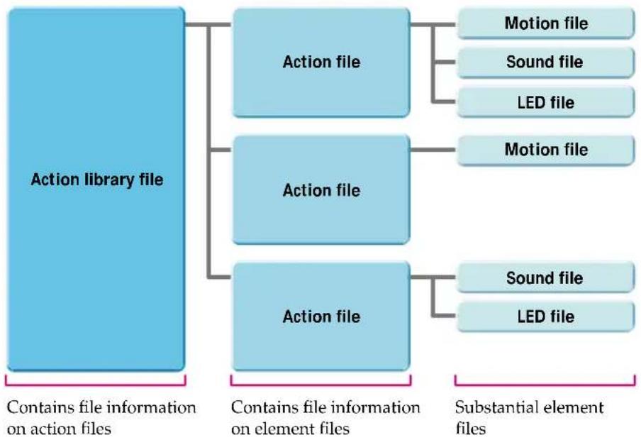
flowchart
graph TD
    A["Action library file"] --> B["Action file"]
    A --> C["Action file"]
    A --> D["Action file"]
    B --> E["Motion file"]
    B --> F["Sound file"]
    B --> G["LED file"]
    C --> H["Motion file"]
    D --> I["Sound file"]
    D --> J["LED file"]
    K["Contains file information on action files"] --> A
    L["Contains file information on element files"] --> A
    M["Substantial element files"] --> K
    M --> L
Window organization
Action Composer is made up of several windows as illustrated below.

flowchart
graph TD
    A["Main window"] --> B["Main Window"]
    B --> C["Action Window"]
    C --> D["Preview Window"]
    D --> E["Notes"]

    subgraph Top view
        F["Motion Viewer*"]
        G["Key frames in a motion are displayed. Use this function to copy key frames."] --> H["Main Window"]
        I["Open this window to edit AIBO's poses (key frames within a motion)."] --> H
    end

    subgraph Middle view
        J["MIDI Window*"]
        K["Open this window to create MIDI sounds for AIBO to play back. The piano roll interface lets you visually check the movement and length of notes."] --> L["Action Window"]
        M["WAVE Window*"]
        N["Open this window to edit WAVE sounds for AIBO to play back."] --> L
    end

    subgraph Bottom view
        O["LED Window*"]
        P["Open this window to create AIBO LED flashing patterns."] --> Q["Preview Window"]
        R["Open this window to preview on-screen an action you've created."] --> Q
    end

    style A fill:#f9f,stroke:#333
    style B fill:#ccf,stroke:#333
    style C fill:#cfc,stroke:#333
    style D fill:#fcc,stroke:#333
    style E fill:#ffc,stroke:#333
    style F fill:#cff,stroke:#333
    style G fill:#ffc,stroke:#333
    style H fill:#ffc,stroke:#333
    style I fill:#ffc,stroke:#333
    style J fill:#ffc,stroke:#333
    style K fill:#ffc,stroke:#333
    style L fill:#ffc,stroke:#333
    style M fill:#ffc,stroke:#333
    style N fill:#ffc,stroke:#333
    style O fill:#ffc,stroke:#333
    style P fill:#ffc,stroke:#333
    style Q fill:#ffc,stroke:#333
Creating and Editing Files
Action library files, action files, and element files can be created in a flowing series or individually. Files can be created by loading and editing existing files, however this section describes how to create new files. Files that you created using previous versions of AIBO Master Studio except sound files can be loaded as AIBO ERS-210 files. (Sound files can be commonly used with AIBO ERS-210/220/310 series).
Creating a library first
This section describes how to create action library files, action files, and element files in that order. Create action library files according to your needs, such as compiling only actions that are necessary for behaviors, or grouping actions for a specific AIBO model.
1 Click the Start button in Windows and choose Programs - AIBO Master Studio - Action Composer.
Action Composer will start.
2 From the menu, select File-New Library.
You can also choose Create New Library in the navigation dialog box. The Select Model dialog box appears.

3 Select your AIBO model.
Select your AIBO model name and click OK.
The Create New Library dialog box appears.
4 Create new library file
Choose where to save the file, input the library name, and click Save. The library file will be created, and the name of the library file you saved will appear as the window title.

Library display area
Detailed information area
Tip
- Choose a file name (such as a model name) that will help you to associate the action library with the behavior program for easy recognition later.
- You can also select File-Properties from the menu, and input Creator/Company/Comment.
5 Create new action file
Either click, or from the menu, select Action-New Action.
The Create Actions dialog box to save action file appears.
6 Save new action file
Choose where to save the file, input action file name, and click Save.
An action file will be created and the action name and action file name will appear in the detailed information area of the Main Window.
Tip
You can also insert comments by selecting Action-Add Comment from the menu.
7 Click to select an action file to edit, and create a new element file
Create element file by choosing the Elements menu in the Main Window.
Motion file (.mtn) Click New Motion
MIDI file (.mid) Click New MIDI
LED file (.led) Click New LED
When you click a menu item, a dialog box appears for saving a file.
Choose where to save the file, input a file name, and click Save. The file will be created and the file name will appear in the detailed information area of the Main Window.
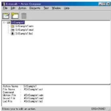
Note
You cannot create WAVE files in Action Composer. If you want to use a WAVE file, prepare it in advance and add it to an action file by choosing Elements-ADD Sound from the menu.
For WAVE file format, see "Principal files" (page 138). You can create WAVE files using software such as the Sound Recorder included in Windows.
8 Open action files
While selecting an action file, either click 📄, or from the menu, select Action-Edit Action.
Action Window will appear.

See "Action Composer" in "Chapter 6 Reference" (page 114) for explanation of Action Window names and functions.
9 Edit elements
Edit motions in the Action Window. Edit sound files in the MIDI or WAVE Window, and LED files in the LED Window. The windows appear when you select Elements-Edit Sound or Elements-Edit LED from the menu. For information about editing elements, see "Editing Elements" (page 82).
Tip
If you are using sound/LED files with data as elements, you can open each window by double-clicking the sound channel or LED channel in Action Window.
10 Save each file
When you finish editing an element, save the element file by selecting File-Save from the menu. Save action files and library files in the same manner.
Creating an action file first
If you already have element files that can be used, you can create action files. Motion files can be created at the same time as action files.
1 Click the Start button in Windows and choose Programs-AIBO Master Studio-Action Composer Tool-Action Window.
The Select model dialog box appears.
2 Select your AIBO model.
Select your AIBO model name and click OK. The Action Window appears.
3 Add elements.
From the Elements menu, select Add Motion, Add Sound or Add LED to add an element.
Tip
You can also create motion files by selecting Elements New Motion from the menu.
4 Save action file.
From the menu, select File-Save As to save the action file.
To include action files that you have created in an action library file, select Action-Add Action from the Main Window menu.
Note
If you add a motion to an action file in the Action Window, then edit the motion and save the action file, the original motion file will also change, so be careful. Try to use a copy of an element when editing as much as possible.
Creating an element file first
If you create and add element files as you have ideas, that will be very convenient, as you will have a wider variety to choose from when creating actions.
Motion file
1 Click the Start button in Windows and choose Programs-AIBO Master Studio-Action Composer Tool-Action Window.
The Select model dialog box appears.
2 Select your AIBO model.
Select your AIBO model name and click OK.
The Action Window appears.
3 Create a motion file.
From the menu, select Elements New Motion to create a motion file.
4 Create a motion.
5 Save the motion.
From the menu, select Element-Save Motion As to overwrite the file created in step 3.
Sound file
Note
You can make simple edits to a WAVE file in the WAVE Window, but you cannot create a new file. If you want to create a new file, use software such as the Sound Recorder included in Windows. For formats to save to, see "Principal files" (page 138).
1 Click the Start button in Windows and choose Programs-AIBO Master Studio-Action Composer Tool-MIDI Window.
The MIDI Window appears.
2 Compose a sound.
3 Save the sound.
From the menu, select File-Save As to save.
LED file
1 Click the Start button in Windows and choose Programs-AIBO Master Studio-Action Composer Tool-LED Window.
The Select model dialog box appears.
2 Select your AIBO model.
Select your AIBO model name and click OK.
A LED Window appears.
4 Save the LED pattern.
From the menu, select File-Save As to save it.
3 Create a LED pattern.
Using action libraries in Behavior Program
Save action library files that you created to a "Memory Stick" by using either a "Memory Stick" drive or by transferring them to AIBO over a wireless LAN. If you save action library files on a "Memory Stick," they will automatically be copied to the computer hard disk so that you can use them in Behavior Arranger and Quick Behavior Arranger.
Note
System files for a different model cannot be saved.
When you use a "Memory Stick" drive
1 Insert a "Memory Stick" with the appropriate system files into the drive.
2 While the action library you created is displayed in the Main Window, select File-Save Library To Memory Stick from the menu.
When you use a wireless LAN
1 Insert a "Memory Stick" with the appropriate system files into AIBO, and boot AIBO.
2 While the action library you created is displayed in the Main Window, select File - Upload Library To AIBO from the menu.
Tip
Information about action library files that you created in Action Composer will be saved in the following files in a "Memory Stick."
\OPEN-R\APP\PC\AMS\ACTION.CFG
\OPEN-R\MW\CONF\ERS-xxx.MWC
\OPEN-R\MW\DATA\AUDIO.ODA
\OPEN-R\MW\DATA\LED.ODA
\OPEN-R\MW\DATA\MOTION.ODA
Editing Elements
This section describes how to edit elements.
Tip
Please refer to the element samples (Sample.alb) and work samples (Extras.alb) in the \Sample\model name folder.
Motion file
Edit motions using the Action Window. Edit individual poses in key frames in the Pose Window.
Editing motions
How to create a new motion
If you create a new motion file, only the start pose and end pose key frames will appear in the Key Frame Channel. If you arrange numbers of poses (key frames) between the start pose and the end pose, intermediary poses will be automatically filled in to create one motion.
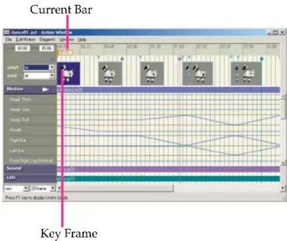
1 Click the position in the motion channel at which you want to create a pose.
The Current Bar will move, and the frame at the current position will be selected.
2 From the menu, choose Edit Motion - Change To Key Frame.
A key frame is created.
3 Edit the pose.
If you double-click the key frame that you created, the Pose Window appears. For details on editing a pose, see "Editing Poses." (page 85)
4 Repeat steps 1 to 3 as necessary to create key frames.
5 Review the motion
If you click Replay button, the Preview Window will appear and the motion will be replayed. For names and functions in the Preview Window, see "Action Composer" (page 114) in "Chapter 6 Reference."
Editing in the motion channel
1 Select the frame you want to edit.
To select a single key frame, click on the key frame. To select subframes other than key frames, move the current bar to select a single frame at the current position. To select sequential key frames together, click the first key frame and then shift-click the last key frame. Selected key frames turn light blue, and the frames turn black.
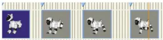
natural_image
Four pixelated cartoon sheep illustrations in a row, each with distinct color and shape (no text or symbols)Tip
When you select a frame, changing the zoom rate in the time range box at the bottom-left corner of the window will help you select more easily.
2 From the Edit Motion menu, choose the edit command you want.
Undo
Cancels the last operation in the key frame channel and returns to the previous state.
Redo
Resume an operation canceled by using Undo.
Cut
Cuts out the selected frame and copies it to the clipboard.
Copy
Copies the selected frame to the clipboard.
Overwrite
Overwrites the clipboard contents onto the current position.
Paste
Pastes the clipboard contents onto the current position.
Delete Frame
Deletes the selected frame. Start and end poses cannot be deleted.
Insert Frame
Inserts a subframe in the current position.
Change To Key Frame
Changes the selected subframe to a key frame.
Use this function to edit a pose in a subframe or adjust the position of a subframe.
Using existing motion files
You can insert an existing motion file into a motion you're working on or copy key frames from an existing motion file.
■ To insert a motion
1 Select the frame where you want to insert the motion.
2 From the menu, choose Elements-Insert Motion and choose the motion file.
The selected motion is inserted before the frame.
Note
You cannot insert a motion in a starting frame.
■ To use a key frame
1 Click the Start button in Windows and choose Programs-AIBO Master Studio-Action Composer Tool-Motion Viewer.
The Motion Viewer window appears.
2 Open a motion file.
From the menu, select File-Open to select a file name. The file's key frame will appear.
3 In the Motion Viewer window, select the frame(s) you want to copy.
Select a key frame as in step 1 of "Editing in the motion channel." To select all the frames, choose Edit-Select All from the menu.
4 From the menu, choose Edit-Copy.
The selected frame(s) is copied to the clipboard.
5 Return to the Action Window and select the frame where you want to insert the frame(s).
6 From the Edit Motion menu, choose Overwrite or Paste.
The copied frame(s) is pasted to the Key frame channel.
Adjusting the positions of key frames
Adjust the position of a key frame to change a movement's timing. All key frames except for the key frame of the start pose can be adjusted.
1 Right-click on a key frame.
The context menu appears.
2 Choose Set Interpolation Frame.
The dialog box appears.

3 Enter the number of subframes from the preceding key frame and click OK.
The key frame moves to the new position.
Tip
1 frame is equivalent to 0.016 second.
To make slight adjustments to the key frame position
Click the motion channel to select a subframe and press the Delete or Insert key on the keyboard. By adding or inserting subframes, you can adjust the position of the key frame.
Editing Poses
Changing start and end poses
In the Key frame channel, choose the poses you want from the start and end combo box. Start and end poses cannot be modified.
Note
Start and end poses are assigned set poses such as stand, sit or sleep. If you use more than one motion in Behavior Arranger and the second motion starts with a pose that is different from the end pose of the first motion, the set poses make it possible for AIBO's built-in program to make a smooth transition from one motion to the next.
Setting up a pose
In the Action Window, double-click a key frame in the key frame channel. The Pose Window will appear for you to define a pose.
A pose is defined by specifying the angles of AIBO's joints for any given moment.
1 Double-click a key frame displayed in the key frame channel.
The Pose Window opens.
2 Select a body part either from the part list or the AIBO graphic, and set the angle.
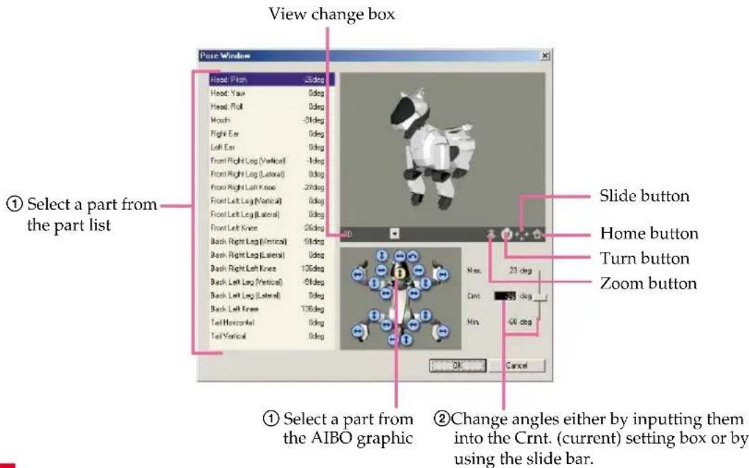
Note
Press the keys on the keyboard to change the angle one degree at a time.
■ To adjust the viewpoint
Choose a viewpoint from the pull-down menu of the switch view box.
Alternatively, select either of the zoom, rotate or pan buttons and drag on the 3D view to adjust the view. Clicking the home position button resets the view to the viewpoint set up in the switch view box (initial setting).
3 When you've adjusted AIBO to the pose you want, click OK.
The Pose Window closes, and the pose in the key frame in the Action Window changes to the new pose.
Precautions on motions
Take the following precautions when making a motion.
For tips on creating motions, see the "Tutorial Guide" advanced course section.
- If the joints move too abruptly from one key frame to another, the graph in the motion channel turns red. Scroll through the motion channel to check for red lines and adjust the motion to make red indications disappear. If a motion with red lines is played back on AIBO, AIBO will not be able to keep up with the designated speed and that may cause AIBO to malfunction. In such a case, though such a file can be saved as a motion file, it cannot be transferred to a "Memory Stick."

Area where the motion is too fast.
- Motions where AIBO's body parts bump into each other, AIBO hits the floor with force, or AIBO falls down heavily may result in AIBO breaking down. If a similar problem occurs when a motion is played back on AIBO, stop AIBO's operation and modify the motion.
- Shorter motions result in better program response.
If a motion lasting longer than 30 seconds is played back on a model ERS-210/220, the motors may be overloaded and AIBO may automatically stop moving.
Do not make motions lasting longer than 30 seconds. - If AIBO plays back a motion that changes abruptly from the start pose, AIBO may incorrectly interpret that it has fallen down.
Editing sound
AIBO uses MIDI and WAVE files for sound effects and melodies. The MIDI and WAVE files are edited in separate windows.
Note
- There are sample media link sounds used in AIBO Pal (ERF-310AW07E) for AIBO ERS-310 series and command sounds (tonal scales) for AIBO ERS-110/111 that you can use as elements. (Behavior Arranger can create programs to respond to these sounds.)
Media link sounds: installed folder \Sample\AiboSound\
Tonal scales: installed folder \Sample\AiboTone\
For the each sound's meaning, see "Media link sounds that can be used for sound recognition" (page 60) and "Tonal scales that can be used for sound recognition" (page 62). - You can play back sound in either edit window, but if you use the Preview Window, you can play back sound in combination with other elements and check the synchronization. If you use a wireless LAN (AIBO ERS-210/220), we recommend that you test sounds on AIBO. For details, see "Executing tests on AIBO" (page 97).
MIDI file
Sounds in MIDI format are created and edited in the MIDI window. In Action Composer, you can make MIDI sounds compatible with AIBO without worrying about format restrictions.
The piano-roll interface with a vertical keyboard and a horizontal time frame lets you make and edit sounds intuitively.
■ Overview of the MIDI Window

Setting basic items
Set the items below before you start composing sound.
| Tempo box Choose the number of beats per minute, in quarter notes. You can choose from 120, 160, and 240 beats/min.* |
| Time box Choose a rhythm. |
| You can choose from 3/4 and 4/4. |
* If MIDI files edited using commercially available tools have tempos other than those above, open such files in the MIDI Window to add the tempo to the list.
Composing sound
Specify the note and place sound data on the score channel.
The velocity (impact) of a sound is indicated by the vertical line in the velocity channel. Change the length of the line to adjust the impact of a sound. The length of a sound data on the score channel indicates the length of a note.
Note
AIBO reproduces only one note at a time (monophonic). You should position sound data so that no more than one note is reproduced at a time. If the notes overlap, the data is converted to monophonic sound when saved to the files.
■ Making sound data
1 Select the note you want and place the sound on the score channel.
If you choose a note, it will change to input mode and the mouse pointer changes to in the score channel. The length of the sound data corresponds to the note chosen. The velocity is set to maximum and the sound is reproduced. In the input mode, sound data is inserted each time you click the score channel.
2 Adjust the sound data as required.
When you place the mouse pointer on an existing sound data, the pointer changes shape depending on the spot and indicates the available editing function. Drag the mouse to make changes.

3 Change the velocity as required.
■ Changing sound data
1 Click .
It switches to select mode.
2 Select the sound data you want from the score channel and make changes.
Click the sound data you want to change. You can drag on the score channel to select several notes at once. To select all sound data on the score channel, choose Edit-Select All from the menu.
Selected sound data is indicated by being surrounded by a black line.
To make changes to a sound data
The mouse pointer changes shape depending on the spot and indicates the available editing function.
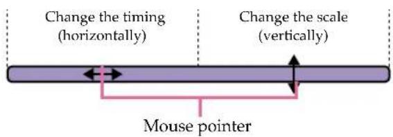
To delete sound data
Press the Delete key on the keyboard.
3 Change the velocity as required.
■ Changing the velocity
You can change the velocity (impact) of a sound by changing the length of the vertical line in the velocity channel. Velocity for several sounds can be changed together.
You can gradually increase or reduce the volume easily by changing the velocity.
Drag over the velocity line
For a weaker impact For a stronger impact
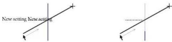
Velocity is set to the point where the line made by the mouse crosses with the vertical line.
■ Editing the overall sound data
1 Select the sound data you want to edit.
Click and choose the sound data that you want to change. You can drag on the score channel to select several notes at once. To select all sound data on the score channel, choose Edit-Select All from the menu.
Selected sound data is indicated by being surrounded by a black line.
2 From the Edit menu, choose the edit command you want.
Undo
Cancels the last operation and returns to the previous state.
Redo
Resume an operation canceled by using Undo.
Cut
Cuts out the selected sound data and copies it to the clipboard.
Copy
Copies the selected sound data to the clipboard.
Paste
Pastes the clipboard contents starting from the current position onto the selected scale.
Insert
Inserts the clipboard contents in the current position for all scales.
Delete
Deletes the selected sound data.
Using existing sound files
You can use MIDI files created with commercially available sound editors and that are in the format described below.
Use Format0 (single-track/multi-channel) Standard MIDI files. If you open a Format0 file in the MIDI Window and then save it, the data will be converted to a format compatible with AIBO. Functions and limitations are as follows:
- Velocity is effective but volume and expression are not supported.
- The tone cannot be changed since program change/bank select are not supported.
- AIBO emits a single sound at a time (monophonic). If notes overlap, the data is converted to monophonic sound when saved in a file.
- AIBO reproduces notes from C4 to B6 (note numbers 60 to 95). When you specify a note beyond this range, C4 is output. The sound quality of notes C4 to B4 (note numbers 60 to 71) is not as good because of the limitations of AIBO's speakers. We recommend that you use notes higher than C5.
- Resolution: 32 ms. (All notes are quantized at 32 ms intervals.) Do not repeat note boundaries during this time (32ms).
- Channel/track: only 0 is valid for each.
- Do not specify a large amount of data other than note boundaries.
WAVE file
You can use WAVE files that were made with commercially available sound editors. Use the WAVE Window to edit WAVE files.
Playback button
Plays back the sound

Wave channel
The waveform of the sound is displayed.
Compatible WAVE files
A WAVE file has a larger data size compared to MIDI files. Avoid using a long WAVE file, or including several WAVE files in a single action library as much as possible. Doing so will affect the amount of space available in the "Memory Stick" for saving other actions.
Sound format
Use WAVE files with audio formats of 8 kHz, 8-bit, monaural, PCM and that are no larger than 2 MB (250 seconds). Before opening a WAVE file in the WAVE Window, check the format using, for example, the Sound Recorder in Windows.
Editing a WAVE file
1 Select the segment you want to edit.
On the WAVE channel, click to select the beginning of the segment then shift-click at the end of the segment. The color of the selected segment turns white.
Tips
If you click the playback button at this point, you can play back the selected segment.
2 From the Edit menu, choose the edit command you want.
Undo
Cancels the last operation and returns to the previous state.
Redo
Resume an operation canceled by using Undo.
Cut
Cuts out the selected sound and copies it to the clipboard.
Copy
Copies the selected sound to the clipboard.
Paste
Pastes the clipboard contents onto the current position.
Insert
Inserts the clipboard contents in the current position.
Delete
Deletes the selected sound.
Fade in
Fades in the selected sound.
Fade out
Fades out the selected sound.
Normalize
Normalizes the selected sound (i.e. changes the gain to adjust the maximum amplitude to 100 percent).
LED file
Flashing LED patterns are created and edited in the LED Window. You can specify the duration and brightness of each LED flash.
All you need to do is select a brightness level for the LED and arrange the LED data in the LED window. The vertical axis represents the LED and the horizontal axis represents time, so you can specify patterns intuitively.
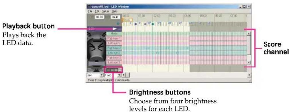
Tips
- Lights that have several LEDs (the ERS-210 tail light and ERS-310 series horn light) can emit mixed colors.
- You can play back LED data in the LED Window, but if you use the Preview Window, you can play back LED data in combination with other elements and check the synchronization. If you use a wireless LAN, we recommend that you test LED data on AIBO. For details, see "Executing tests on AIBO" (page 97).
Note
The ERS-220 retractable headlight opens and closes its cover in response to LED lighting. Do not turn the headlight on and off within 500ms due to restrictions regarding opening and closing the structure. Please be careful because Action Composer doesn't have a function to check this.
Creating LED data
Select a brightness level and arrange the LED data in the LED window.
The length of the arranged LED data corresponds to the duration of the light.
Specifying LED data
1 Select the brightness level and place LED data on the score channel.
If you click a LED on the LED plan, it will go into input mode so you can see the corresponding score channel.
The mouse pointer changes to in the score channel.
When an LED data is placed on the score channel, the corresponding LED in the diagram lights up.
Tip
Data will be created with the same duration that was set the last time.
Note
The ERS-220 retractable headlight has one brightness level.
2 Adjust the LED data as required.
When you place the mouse pointer on an existing LED data, the pointer changes shape depending on the spot and indicates the available editing function. Drag the mouse to make changes.
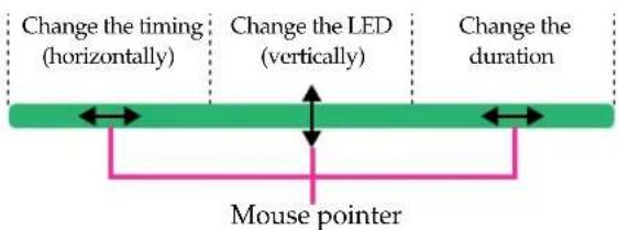
Changing LED data
1 From the menu, Select Setup - Select Mode.
2 Select the LED data you want from the score channel and make changes.
Click the LED data you want to change. You can drag on the score channel to select several LED data at once.
To select all LED data on the score channel, choose Edit-Select All from the menu.
Selected sound data is indicated by being surrounded by a black line.
To make changes to LED data
The mouse pointer changes shape depending on the spot and indicates the available editing function.

To delete LED data
Press the Delete key on the keyboard.
To change the brightness level
Click the brightness button you want.
Editing overall LED data
1 Select the LED data you want to edit.
Select Setup - Select Mode from the menu, and choose the LED data that you want to change. You can drag on the score channel to select several LED data together. To select all LED data on the score channel, choose Edit-Select All from the menu Selected LED data is indicated by a black line around it.
2 From the Edit menu, choose the edit command you want.
Undo
Cancels the last operation and returns to the previous state.
Redo
Resume an operation canceled by using Undo.
Cut
Cuts out the selected LED data and copies it to the clipboard.
Copy
Copies the selected LED data to the clipboard.
Paste
Pastes the clipboard contents starting from the current position onto the selected LED.
Insert
Inserts the clipboard contents in the current position for all LEDs.
Delete
Deletes the selected LED data.
Synchronizing elements
In Action Composer, you can synchronize the three elements by adjusting the starting point of a sound or by using markers.
Adjusting the starting point of a sound file
You can adjust the point where a sound file (WAVE/MIDI) begins playback. To make adjustments within an element use the markers.
1 In the Action Window, choose Elements-Set Sound Start Point from the menu.
The Sound Start Point dialog box appears.

2 Specify the starting time in frames and click OK.
The file shifts to the new starting point.
Note
One frame equals 0.016 seconds.
Using markers
You can use markers in elements that are part of actions.
In the Action, MIDI, WAVE and LED Windows, light-blue markers appear in the key frame channel to indicate the positions of key frames. Refer to these markers when synchronizing sound and LED data with motion. You can also add separate markers in the MIDI, WAVE and LED Windows and refer to these markers to adjust the motion to sound or LED data.
Adding markers
In each Window, click the marker channel while pressing the Alt key.
A marker appears, its color depending on the Window type. A marker placed in one Window will also appear in the other Windows.

Action Window (Blue)

MIDI/WAVE
Window
(Purple)

LED
Window
(Green)
To erase a marker
In the Window where the marker was made, click the marker while pressing the Alt key. The marker will be erased from all four Windows.
Note
Markers can be used when the element is part of an action. If you open an element file directly and edit it independently from an action, the maker function cannot be used.
Open markers from the Action window instead of directly opening the Sound/LED window from the Main window.
Checking elements and actions
You can check elements and actions that you created with Action Composer by playing them back on a PC or by transferring them to AIBO over a wireless LAN environment (ERS-210/220).
Previewing on the PC
You can check actions that you created by playing them back on the PC.
Click (Play back button) in the Action Window.
Elements selected in the Preview Window will be played back in synchronization.
You can preview all elements in the Action Window at the same time in this window.
Click the ▶ button to see it again.

natural_image
3D model of a white animal toy with black spots displayed in a software interface (no text or symbols on the model itself)Playback button
When you finish, click ✗ to close the Preview Window.
Executing tests on AIBO
You can check overall actions, or individual elements by transferring them to AIBO over a wireless LAN environment to play them back. Motions in particular aren't accurately simulated on a PC, so we recommend you replay them on AIBO to check them out as you create them.
Note
Only actions and elements included in action libraries can be tested.
1 Select an action or an element
In Action Composer's Main Window, click an action or element file.
2 Transfer an action or element file
From the menu, choose Test, and the file that you want to run.
Action file [Test Action]
Motion file [Test Motion]
Sound file [Test Sound]
LED file [Test LED]
A connection will be established with AIBO, and the Test Play dialog appears.

3 Test run
Click Play to start the test. Click Close when the test is completed.
Printing windows
You can print action library files that you have created to check the component information of each action. You can also print the Action/WAVE/MIDI/LED windows. Set up the page before you print.
Page Setup
1 From the menu, choose File-Page Setup.
The Print Setup dialog box appears.
2 Set Printer, Paper, and Orientation.
3 Click OK.
1 From the menu, choose File-Print.
The Page Setup dialog box appears.
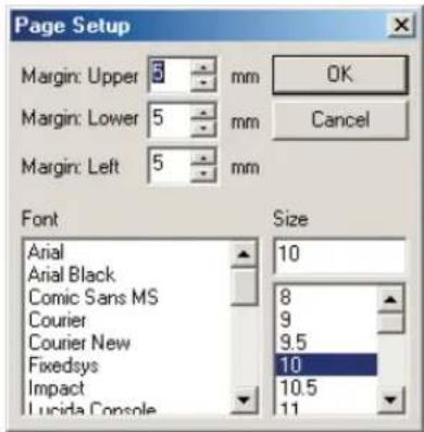
Note
The Print dialog box appears in the Action/WAVE/MIDI/LED windows. Specify a printer, printing range, and number of copies, and click OK.
2 Set margins, font, and point size.
3 Click OK.
Importing/exporting files
Action Composer can import/export library files, and export action files.
Import/export of action library files
You can import and export an action library file in plb (Packed action LiBrary) format. This enables you to easily exchange action libraries with other AIBO Master Studio users and move libraries between PCs.
Importing
1 From the menu in the Action Composer Main Window, choose File-Import Library.
2 Choose a file name (.plb) to import.
3 Choose a folder in which to extract the file.
Extracted content will be saved, and the action will be added to an open library file (.alb) automatically at the same time.
Exporting
1 From the menu in the Action Composer Main Window, choose File-Export Library.
2 Specify export destination and a file name (.plb) to save.
The action library will be exported, and a plb format file will be created.
Using other AIBO-ware action files
If you export action files to axf (Action Export File) format files, actions can be imported and used depending on the AIBO-ware application. For instructions on importing actions, see each AIBO-ware application's user's guide.
Exporting action files
1 In the Action Composer Main Window, choose an action to export, and from the menu, choose Action-Export Action.
The Action Data dialog box appears.

2 Input Creator, Company, and Comment, and click OK.
3 Select the location to export to and the file name (.axf), and save it.
AIBO Master Studio
Chapter 6
Reference
Troubleshooting
If you experience any of the following difficulties, use this troubleshooting guide to remedy the problem. Refer also to the Readme/FAQ information located in the folder where AIBO Master Studio is installed. Should the problem persist, please contact AIBO Customer Link.
| Symptom | Remedy |
| The software cannot be installed from the CD-ROM. | There isn't enough space in the hard disk.Check the hard disk space. If several drives are available, choose a hard disk with adequate space, other than drive C.The CD-ROM's auto-play function is switched off.Execute the "Setup.exe" file in the CD-ROM.Other programs are running.First end all programs and then redo setup.You're attempting to install the software to Windows NT/Windows 3.1/Windows 95.This software runs only on Windows 98 SE/Me/2000 Professional/XP. Install the software to a PC running on a compatible OS.The VGA is set to less than 800 · 600 and/or less than 16-bit colors.Set VGA to 800 · 600 or greater and 16-bit colors or greater.You're attempting to install the software to Windows 2000 Professional/XP as a general user.To install, log on as an administrator or an Administrator's Group member. |
| An application does not start up. | There are not enough system resources.End all other programs that are running.Installed files are damaged.Uninstall AIBO Master Studio, then reinstall the software from the CD-ROM (page 20).Battery is lowTo be safe, AIBO will stop acting and lie on its stomach. Charge the battery. |
| Data cannot be written to the “Memory Stick.” | The “Memory Stick” is not inserted correctly.→Check that the “Memory Stick” is inserted in the drive correctly.The “Memory Stick” drive is set incorrectly.→Set the drive correctly in the AIBO Master Studio Setup window (page 20).System files hasn’t been copied.→To use a “Memory Stick” with AIBO Master Studio, you need to copy the appropriate system files for your AIBO to the “Memory Stick” (page 21).The safety switch on the “Memory Stick” is set to LOCK.→Set the switch on the “Memory Stick” to the write-enable position (page 105). |
| When the “Memory Stick” is removed from the PC, the PC screen turns blue and displays a disk-read-error message. | The “Memory Stick” was removed before the PC had completed writing data on the “Memory Stick.”→Insert the “Memory Stick” again and press the Enter key; wait a while then remove the “Memory Stick.” |
| AIBO is not correctly rendered in the Preview Window. | The graphic driver is not the latest version.→The 3D image of AIBO is rendered using OpenGL. OpenGL is processed with the graphic driver or hardware depending on the graphic card used. Please contact the manufacturer of your PC or graphic card. |
| AIBO stops in mid-movement. | A long motion was played back (ERS-210/220).→If AIBO tries to execute a motion that is longer than 30 seconds, the motors are strained and AIBO may automatically stop moving. To return AIBO to normal, press the head sensor for 3 seconds or more for ERS-210, and push the head sensor toward the front for 3 seconds or more for ERS-220.AIBO is heating up.→The pause light goes off, and AIBO stops moving. Do not move AIBO until it cools down. When making a program, avoid arranging strenuous motions one after the other.Battery is low→To be safe, AIBO will stop acting and lie on its stomach. Charge the battery. |
| AIBO emits a sad melody and does not move when its pause button is pressed. | Battery is lowTo be safe, AIBO will stop acting and lie on its stomach. Charge the battery.The “Memory Stick” contains commercially available AIBO-ware.You cannot execute programs on AIBO using a commercially available AIBO-ware “Memory Stick” that already contains an application for operating AIBO such as “AIBO Life.”A “Memory Stick” with system files for different AIBO models is used.Copy the system files in AIBO Master Studio Setup.The data in the “Memory Stick” is damaged.Delete the OPEN-R folder on a “Memory Stick” using Windows Explorer. Then copy the system files again using AIBO Master Studio Setup (page 21), and save data from each application again. |
| AIBO does not move when connected to a wireless LAN (ERS-210/220) | The AIBO Wireless LAN Card is not inserted in AIBO.Insert the AIBO Wireless LAN Card in AIBO.The IP address for the wireless LAN is not set.The IP address of the AIBO Wireless LAN Card inserted in AIBO needs to be registered in AIBO Master Studio. (page 23)The PC is not set up for wireless LAN communication.Check that a wireless LAN card is inserted in the PC or that the PC connects to a wireless LAN access point. (page 24)User ID and password are wrong.Input a new user ID and password into the “Memory Stick” by using AIBO Master Studio Setup. (page 23) |
| Isn’t connected to a wireless LAN (ERS-210/ERS-220) | You removed the AIBO wireless LAN card and booted AIBO.Redo wireless LAN information setup (page 23). |
"Memory Stick"
Suitable "Memory Stick" products
AIBO uses an entertainment-robot-dedicated "Memory Stick" as media to record behavior programs. Programs created and edited with AIBO Master Studio should be saved to the supplied "Memory Stick" (including old version accessories) or to a separately sold "AIBO Programming Memory Stick" and then executed on AIBO. The "Memory Stick" is the interface between your AIBO and the PC. In order to use either of the "Memory Sticks" you first need to copy system files to it to use it in AIBO Master Studio. For details, see "Making a 'Memory Stick' appropriate for your AIBO model" (page 21).
Handling procedures
About the safety switch
If the safety switch of the "Memory Stick" is set to LOCK, data cannot be saved or erased. Do not set the safety switch to LOCK when using AIBO Master Studio.

Precautions on writing to the "Memory Stick"
- Do not format the "Memory Stick" by using the Windows or MS-DOS format commands. If formatted, the "Memory Stick" may not be correctly recognized.
- If you use the "Memory Stick" with the safety switch set to LOCK, the symptoms below may appear. These symptoms do not indicate malfunction of the "Memory Stick" or the "Memory Stick" drive.
- The message "Unable to write to disk in drive D*: Data or files may be lost." appears on the PC screen. (* The drive letter differs depending on your PC system.)
- Icons for data that cannot be written remain displayed on the PC screen. (The icons will disappear when the "Memory Stick" is removed.)
- Data stored in the "Memory Stick" may be erased or damaged in the following cases:
- If the "Memory Stick" is removed or the PC switched off while reading or writing data.
- If the "Memory Stick" is used in a place subject to static electricity or electric noise.
Removing the "Memory Stick" from the PC card adapter
To remove the "Memory Stick" from the PC card adapter, click the icon in the Windows taskbar for the "Memory Stick" slot drive and then click Stop Standard IDE/ESDI Hard Disk Controller.
Wait for the message "You may safely remove this device" to appear before removing the "Memory Stick."
Note
After the PC finishes writing data to the "Memory Stick," wait for a while before removing the "Memory Stick." (If your PC is equipped with a "Memory Stick" slot, wait for approximately 15 seconds.) If you remove the "Memory Stick" immediately after data is written, the monitor screen may turn blue and an error message indicating disk read error may be displayed. If this occurs, insert the "Memory Stick" again and press the Enter key; wait for a while and then remove the "Memory Stick."
Precautions on use
To protect the "Memory Stick" from damage and malfunction, observe the following:
- To remove the "Memory Stick" from AIBO while it is still operating, first push the pause button to stop AIBO movements, and make sure that it is safe to remove it before doing so.
- Do not touch terminal with your hand or metal objects.
- Do not stick anything other than a dedicated "Memory Stick" sticker in the area indicated by .
- Do not bend, drop or apply strong physical shock to the "Memory Stick."
- Do not disassemble or modify the "Memory Stick."
- Do not let the "Memory Stick" get wet.
- Do not use or store the "Memory Stick" in places subject to:
– Excessively high temperature, such as a car parked in the sun
- Direct sunlight
– High humidity or corrosive gas
- When carrying or storing the "Memory Stick," keep it in the supplied case.

Specifications
Memory Flash memory
Capacity 8 MB
Voltage 2.7 V to 3.6 V
Power consumption
Approx. 45 mA, average operation
Max. 130 μA, standby
Write speed Max. 1.5 MB/s
Read speed Max. 2.45 MB/s
Operating temperature
0 °C to 60 °C (32 °F to 140 °F), without condensation
Dimensions Approx. 21.5 · 50.0 · 2.8 mm (0.85 · 1.97 · 0.11 in.) (w/h/d)
Mass Approx. 4 g (0.14 oz)
Design and specifications are subject to change without notice.
Behavior Arranger
Names and functions of the window
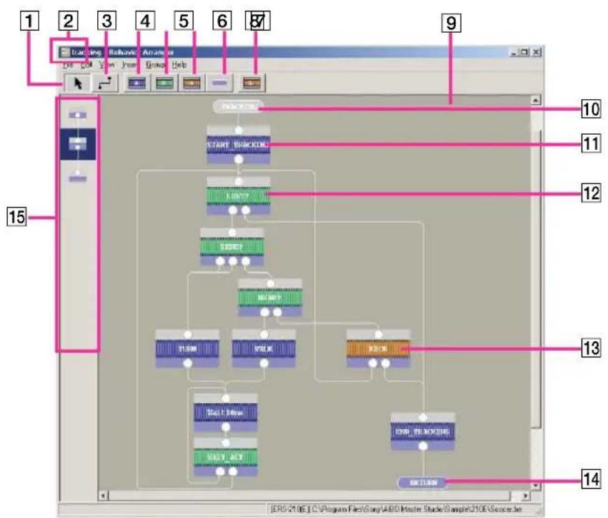
flowchart
graph TD
    A["Start"] --> B["START"]
    B --> C{Check?}
    C --> D{OK?}
    D --> E["END"]
    E --> F{OK?}
    F --> G{OK?}
    G --> H{OK?}
    H --> I{END Block}
    I --> J{OK?}
    J --> K["END Block"]
    style A fill:#f9f,stroke:#333
    style K fill:#bbf,stroke:#333
1 Mouse: Normal mode button
Sets the mouse function to normal mode. This button has the same function as the menu's Edit-Mouse:Normal Mode.
2 Group name
The name of the group in the window. The group at the top level is Main.
3 Mouse: Link mode button
Sets the mouse function to link mode. This button has the same function as the menu's Edit-Mouse:Link Mode.
4 Action box button
Inserts an action box. When this button is clicked, the Action Properties dialog opens. This button has the same function as the menu's Insert-Action Box.
5 Branch box button
Inserts a branch box. When this button is clicked, the Branch Properties dialog opens. This button has the same function as the menu's Insert-Branch Box.
6 Group box button
Inserts a group box. When this button is clicked, the Group Properties dialog opens. This button has the same function as the menu's Insert-Group Box.
7 Terminal box button
Inserts a terminal box. When this button is clicked, the Terminal Properties dialog opens. This button has the same function as the menu's Insert-Terminal Box.
8 Library box button
Inserts a library. When this button is clicked, the Open dialog opens. This button has the same function as the menu's Insert-Library.
9 Edit window
This is where you make a program.
10 Terminal box (gray)
Indicates the start of a program. The box name is START in the Main group and ENTRY in a new group.
11 Action box
A box that specifies sequential actions.
12 Branch box
A box that specifies branch conditions.
13 Group box
A box that specifies the group (subroutine) to be activated.
14 Terminal box (blue)
Indicates the end of a program. The box is named END in the Main group and RETURN in a new group.
15 History bar
Displays group levels.
Menus
File
New
Creates a new program. A Main group containing just the START and END terminal boxes is displayed.
Open
Opens a program saved in a behavior file (*.be).
Save
Saves the program over an existing file (*.be).
Save As
Saves the program with a new filename.
Recent Files
Displays the four files used most recently.
Save to Memory Stick
Saves a behavior file to the "Memory Stick" in the drive.
Wireless LAN Connection
This feature can be used when wireless LAN is set up. Connecting to wireless LAN lets you upload a program and execute the behavior on AIBO.
Page Setup
Set page parameters to print a Behavior Program.
Print a Behavior Program.
Exit
Ends Behavior Arranger.
Edit
Undo
Cancel the last operation and return to the previous state.
Redo
Resume an operation canceled using Undo.
Cut
Cuts out the selected box.
Copy
Copies the selected box.
Paste
Pastes the box that was copied.
Program Comments
Adds comments to the program.
Mouse: Normal Mode
Sets the mouse to normal mode.
Mouse: Link Mode
Sets the mouse to link mode. Connect boxes by dragging the mouse from the first box to the next.
Select All
Selects all the boxes in the edit window.
View
Toolbar
Switches on/off the toolbar display.
History Bar
Switches on/off the history bar display.
Status Bar
Switches on/off the status bar display.
Scroll Bar
Switches on/off the scroll bar display.
Resize Edit Range
Sets the size of the edit area. The area cannot be set to a size smaller than the current edit window.
Normal View
Displays a standard-sized flowchart (boxes) in the edit window.
Reduced View [50%]
Reduces the flowchart (boxes) in the edit window to half the normal size.
Reduced View [25%]
Reduces the flowchart (boxes) in the edit window to a quarter of the normal size.
Design View
Sets preferences for the appearance of the edit window.
Insert
Action Box
Inserts an action box.
Branch Box
Inserts a branch box.
Group Box
Inserts a group box.
Terminal Box
Inserts a terminal box.
Library
Inserts a library in the program being edited.
The library takes the form of a group box.
Group
Create New Group
Creates a new group.
Delete this Group
Deletes the displayed group. Deleting the group will not delete the group box that calls that group.
Rename Group
Changes the name of the displayed group.
View Group Image
Shows the image (.bmp) added to the displayed group.
Add Image to Group
Adds an image (.bmp) to the displayed group.
Delete Image from Group
Deletes the image (.bmp) from the displayed group.
Set Order of Terminals
Changes the order of the terminals on a group box.
Group List
Displays the group list. Double-click a group name to open that group.
Group Tree
Displays the group tree. Double-click a group name to open that group.
Open All Groups
Opens the edit windows of all groups.
Close All Groups
Closes the edit windows of all groups (excluding the Main group).
Help
User's Guide
Opens this User's Guide.
Command Reference
Displays the Command Reference.
Tutorial Guide
Opens the Tutorial Guide.
AIBO Homepage
Opens AIBO's homepage. To use this feature, your PC needs to be connected to the Internet and set up with an Internet browser.
About Behavior Arranger
Displays the application's version information.
Mouse operation
Edit window
Mouse operations in the edit window are as follows:
Left click
On a box:
selects the box
On a connection line:
selects the connection line:
Left double-click
Displays properties, opens a group.
Left drag
On a box:
moves the box (when mouse is in normal mode).
connects boxes (when mouse is in link mode).
Outside a box:
selects an area (when mouse is in normal mode).
On a connecting line:
moves the line.
Ctrl + left click
On a box or connecting line:
selects several boxes or connecting lines.
Ctrl + left drag
On a box:
connects boxes (when mouse is in normal mode).
moves the box (when mouse is in link mode).
Right click
On a box:
displays the context menu for editing the box.
On a connection line:
displays the Delete Connection context menu.
Outside a box:
displays the same context menu as the Insert menu.
On the terminals of a group or branch box:
displays the context menu for editing the box.
Others
- When you place the mouse on the terminal of a group or branch box, terminal information is displayed.
- A drag operation can be cancelled by pressing the Esc key.
History bar
Mouse operations in the history bar are as follows:
Left double-click
Opens the chosen group in the edit window.
Place the mouse pointer over a box in the history bar
Displays the group name.
Keyboard operation
Edit window
Keyboard operations in the edit window are as follows:
Directional keys ( )
Moves the pointer.
Shift + directional keys (← → ↑ ↓)
Moves boxes.
Ctrl + Shift + directional keys (← → ↑ ↓)
Moves connecting lines.
Ctrl + directional keys (← → ↑ ↓)
Scrolls the edit window.
Application key
Displays the context menu.
Enter
Displays the box's properties.
Shift + Enter
Opens a group.
Esc
Aborts an operation.
Manipulating files
Ctrl + N Makes a new file.
Ctrl + O Opens a file.
Ctrl + S Saves over an existing file.
Editing
Delete/Ctrl + X Cuts.
Ctrl + C Copies.
Insert/Ctrl + V Pastes.
Ctrl + A Selects all.
Making selections
Space bar Makes a single selection.
Ctrl + space bar
Makes several selections.
Tab Jumps to next selection.
Function keys
F1 Displays the User's Guide
F2 Enter program comments.
F3 Sets mouse to normal mode.
F4 Sets mouse to link mode.
F5 Creates an action box.
F6 Creates a branch box.
F7 Creates a group box.
F8 Creates a terminal box.
F9 Inserts a library.
F10 Displays the group list.
F11 Displays the group tree.
F12 Displays AIBO's homepage.
History bar
Keyboard operation lets you jump among boxes as follows:
Home To the Main group
End To the group at bottom of the history bar
Page Up To the group right above in the history bar
Page Down To the group directly below in the history bar
Action Composer
Main window
Names and functions of window

1 New Action button
Creates a new action.
2 Edit Action button
Edits the selected action. Clicking this button opens the Action Window.
3 Delete Action button
Deletes the selected action. Deleting an action will not delete element files.
4 Library display area
Shows the tree organization of action and element files. You can select a file to add, edit or delete.
The actions displayed in this area are managed by a single library file. The library filename is displayed in the title bar.
5 Detailed information area
Detailed information of the selected action is displayed in this area.
Menus
File
New Library
Creates a new action library.
Open Library
Opens a library saved in the action library file (.alb). Actions and elements in a library are opened at the same time and can be edited.
Save Library
Saves the library to an existing file (alb.).
Save Library As
Saves the opened library with a new filename.
Prints Action Library file content information.
Print Preview
Displays the Page Setup dialog to view a print preview.
Page Setup
Changes page printing settings.
Recent files
Displays up to the last four recently used files.
Save Library To Memory Stick
Saves the library to the "Memory Stick."
Upload Library To AIBO
This feature can be used if wireless LAN is set up. Using wireless connection, the library is uploaded to the "Memory Stick" in AIBO.
Import Library
Imports the contents of a Library file.
Export Library
Exports the contents of an Action Library file.
Properties
Displays/inputs properties of the specified action library file.
Exit
Ends Action Composer.
Edit
Undo
Cancels the last operation and returns to the previous state.
Redo
Resumes an operation canceled using Undo.
Cut
Cuts selected actions and elements, and copies them to the clipboard.
Copy
Copies selected actions and elements to the clipboard.
Paste
Inserts the clipboard contents without renaming its elements.
Paste Renamed Selection
Inserts the clipboard contents and renames its elements.
Action
New Action
Creates a new action and adds it to the specified library.
Add Action
Adds an existing action to the specified library.
Edit Action
Edits the specified action. The Action Window appears.
Delete Action
Deletes the specified action.
Rename Action
Changes the name of the specified action.
Add Comment
Add comments to the specified action.
Export Action
Exports an action to axf format.
Elements
New Motion
Creates a new motion and adds it to the specified action.
Add Motion
Add an existing motion to the specified action.
Preview Motion
Displays key frames of the specified motion on a timeline. The Motion Preview window appears.
Delete Motion
Deletes the specified motion.
New MIDI
Creates a new MIDI file and adds it to the specified action.
Add Sound
Adds an existing sound file to the specified action.
Edit Sound
Edits the specified sound.
Delete Sound
Deletes the specified sound.
New LED
Creates a new LED file and adds it to the specified action.
Add LED
Adds an existing LED file to the specified action.
Edit LED
Edits the specified LED file.
Delete LED
Deletes the specified LED file.
Test
Test Action
You can use this function if you have a wireless LAN connection. Transfers selected actions to AIBO for testing.
Test Motion
You can use this function if you have a wireless LAN connection. Transfers selected motions to AIBO for testing.
Test Sound
You can use this function if you have a wireless LAN connection. Transfers selected sounds to AIBO for testing.
Test LED
You can use this function if you have a wireless LAN connection. Transfers selected LED actions to AIBO for testing.
Window
Toolbar
Switches on/off the tool bar display.
Status bar
Switches on/off the status bar display.
Options
Switches the navigation dialog box on/off when the program starts.
Help
User's Guide
Opens this User's Guide.
Tutorial Guide
Opens this Tutorial Guide.
AIBO Homepage
Opens AIBO's homepage. To use this feature, your PC needs to be connected to the Internet and set up with an Internet browser.
About Action Composer
Displays the application's version information.
Action Window
Names and function of window

1 Current time/frame display
Indicates the current position in seconds (unit: 1/100 s) or frames (1 frame = 0.016 s).
2 Total time/frames display
Shows the total time (unit: 1/100 s) or frames of the action.
3 Current bar
Indicates the current position. The tab shows the time (unit: 1/100 s) or number of frames. When you click on the time/frame channel, the current bar moves and the clicked point becomes the current position.
4 Key frame
A frame that defines a pose in the motion. The start and end poses (blue background) cannot be modified. When you double-click a key frame, the Pose Window opens.
5 Action marker (blue)
A mark you make in the Action Window as an aid to synchronizing elements.
A mark you make in the MIDI or WAVE Window as an aid to synchronizing elements.
7 LED marker (green)
A mark you make in the LED Window as an aid to synchronizing elements.
8 Time/frame channel
A channel for changing the current position. When you click on the channel, the current bar moves to the clicked point.
9 Marker channel
Markers added in each Window and (light blue) marks indicating key frame position are displayed together in this channel. When you click on the channel while pressing the Alt key, an action marker appears. To delete a marker, click on the marker while pressing the Alt key.
10 Key frame channel
Key frames in a motion added to the action are displayed in this channel.
11 Motion channel
When a motion is added to the action, this channel shows the transition of each joint angle. If a joint is set to move too quickly, it is highlighted in red.
12Sound channel
The sound file added to the action is displayed in this channel. When you double-click the file, the MIDI or WAVE Window is displayed.
13 LED channel
The LED file added to the action is displayed in this channel. When you double-click the file, the LED Window is displayed.
14 Time interval change box
Choose from among eight levels in the time/frame display interval for the time/frame channel: 4 frames/8 frames/20 frames/ ^1/_2 sec/1 sec/2 sec/4 sec/10 sec.
15sec/frame box
Switches display units
16Playback button
Plays back motions in the Preview Window.
17 End pose box
Choose a pose to end the motion.
18 Start pose box
Choose a pose to start the motion.
Menus
File
New
Creates a new action that is not included in the library. To use this action file after completion, choose Action-Add Action from the Library window and add the action to that library.
Open
Opens an existing action file. To use this action file after completion, choose Action-Add Action from the Library window and add the action to that library.
Save
Saves the displayed action file.
Save As
Saves the displayed action file with a new filename. To use this action file after completion, choose Action-Add Action from the Library window and add the action to that library.
Page Setup
Changes printer page settings.
Prints time/frame channel, key frame position, joint angle change graph, sound bar, and LED bar.
Recent file
Displays up to the last four recently used files.
Properties
Displays/inputs properties of the specified action file.
Exit
Closes the Action Window.
Edit Motion
Undo
Cancels the last operation in the key frame channel and returns to previous state.
Redo (R)
Resume an operation canceled by using Undo.
Cut
Cuts out the selected frame and copies it to the clipboard.
Copy
Copies the selected frame to the clipboard.
Overwrite
Overwrites the clipboard contents onto the current position.
Paste
Pastes the clipboard contents onto the current position.
Delete Frame
Deletes the selected frame.
Insert Frame
Inserts a subframe in the current position.
Change To Key Frame
Changes the current subframe to a key frame.
Select All
Selects all frames.
Elements
New Motion
Creates a new motion.
Add Motion
Opens an existing motion file and displays it in the motion channel and in the key frame channel.
Insert Motion
Inserts a motion file in the current position.
Delete Motion
Deletes the displayed motion.
Save Motion As
Saves the displayed motion with a new filename.
Add Sound
Opens an existing sound file and displays it in the sound channel.
Edit Sound
Edits the sound that is displayed. The MIDI or WAVE Window appears.
Delete Sound
Deletes the displayed sound.
Set Sound Start Point
Changes the starting position of the sound.
Add LED
Opens an existing LED file and displays it in the LED channel.
Edit LED
Edits the LED file that is displayed. The LED Window appears.
Delete LED
Deletes the displayed LED file.
Window
Preview Window
Displays the Preview Window.
AIBO Color
Changes AIBO color.
Help
User's Guide
Tutorial Guide
AIBO Homepage
About Action Composer
Refer to section on the Main window (page 114).
Pose Window
Names and function of window

13D view
Displays a 3D view of AIBO.
2 Zoom button
Zooms in /out the 3D AIBO. Click this button, then drag on the 3D view.
3 Rotate button
Rotates the 3D AIBO. Click this button, then drag on the 3D view.
4 Pan button
Pans the 3D AIBO. Click this button, then drag on the 3D view.
5Home position button
Resets the 3D AIBO to the viewpoint set in the switch view box.
6 Max. setting box
Indicates the maximum angle setting.
7 Crnt. (Current) setting box
Enter a number to set the angle.
8 Min. setting box
Indicates the minimum angle setting.
9 Angle slide bar
Slide to set the angle of the selected joint.
10Diagram of AIBO
Click a part to select it. When you select a part from the list, the selected part will be highlighted in the graphic.
11Switch view box
Switch the viewpoint of the 3D AIBO.
12 Parts list
A list of AIBO parts that can be set to different angles. Select the part whose angle you want to change.
MIDI Window
Names and function of window

1 Current time/frame display
Indicates the current position in seconds (unit: 1/100 s) or frames (1 frame = 0.016 s).
2 Total time/frames display
Shows the total time (unit: 1/100 s) or frames of the sound.
3 Current bar
Indicates the current position. The tab shows the time (unit: 1/100 s) or number of frames. When you click on the time/frame channel, the current bar moves and the clicked point becomes the current position.
4 Action marker (blue)
A mark you make in the Action Window as an aid to synchronizing elements.
A mark you make in the MIDI or WAVE Window as an aid to synchronizing elements.
6 LED marker (green)
A mark you make in the LED Window as an aid to synchronizing elements.
7 Time/frame channel
A channel for changing the current position. When you click on the channel, the current bar moves to the clicked point.
8 Marker channel
Markers added in each Window and (light blue) marks indicating key frame position are displayed together in this channel. When you click on the channel while pressing the Alt key, a sound marker appears. To delete a marker, click on the marker while pressing the Alt key.
9 Score channel
The area where sound is composed by placing sound data. Scales that AIBO can play back are highlighted.
10 Velocity channel
The channel where sound impact is specified for each sound data. When a sound data is first placed, it is set to the maximum velocity; the velocity can then be adjusted with the mouse.
11Sound data
Specifies the length and scale of a single note.
12 Select button
It switches to select mode, and enables you to select sound data you have prepared.
13 Time interval change box
Changes the time interval displayed for a channel. Choose from among eight levels in the time/frame display interval for the time/frame channel: 4 frames/8 frames/20 frames/ ^1 / _2 sec/1 sec/2 sec/4 sec/10 sec.
14Sec/frame box
Switches the display unit.
15 Notes list
Select the note you want for the sound data. If you select a note, it switches to input mode.
16 Time box
Select the meter.
17Tempo box
Select the number of beats to a minute, in quarter notes.
18Playback button
Plays back the sound data on the score channel.
Menus
File
New
Creates a new MIDI file.
Open
Opens an existing MIDI file and displays it in the score channel.
Save
Saves the displayed MIDI file to an existing file.
Save As
Saves the displayed MIDI file with a new filename.
Page Setup
Changes printer page settings.
Prints MIDI file.
Insert
Inserts a MIDI file in the current position.
Recent files
Displays up to the last four recently used MIDI files.
Exit
Closes the MIDI Window.
Edit
Undo
Cancels the last operation and returns to the previous state.
Redo
Resume an operation canceled by using Undo.
Cut
Cuts out the selected sound data and copies it to the clipboard.
Copy
Copies the selected sound data to the clipboard.
Paste
Pastes clipboard contents onto the current position.
Insert
Inserts clipboard contents in the current position.
Delete
Deletes selected sound data.
Select All
Selects all sound data on the score channel.
Setup
Input Mode
Sets the mode for making sound data. This operation is the same as choosing notes.
Select Mode
Sets to the mode for editing sound data. Sets the mode for editing sound data. This operation is the same as choosing ▶.
MIDI Device
Selects an output device for MIDI sound. If a sound card does not exist or is not set up, the output device is not shown. MIDI tones can be selected on the PC.
Help
User's Guide
Tutorial Guide
AIBO Homepage
About Action Composer...
Refer to the section on the Main window (page 114).
WAVE Window
Name and function of window

1 Current time/frame display
Indicates the current position in seconds (unit: 1/100 s) or frames (1 frame = 0.016 s).
2 Total time/frames display
Shows the total time (unit: 1/100 s) or frames of the sound.
3 Current bar
Indicates the current position. The tab shows the time (unit: 1/100 s) or number of frames. When you click on the time/frame channel, the current bar moves and the clicked point becomes the current position.
4 Action marker (blue)
A mark you make in the Action Window as an aid to synchronizing elements.
A mark you make in the MIDI or WAVE Window as an aid to synchronizing elements.
6 LED marker (green)
A mark you make in the LED Window as an aid to synchronizing elements.
7 Time/frame channel
A channel for changing the current position. When you click on the channel, the current bar moves to the clicked point.
8 Marker channel
Markers added in each Window and (light blue) marks indicating key frame position are displayed together in this channel. When you click on the channel while pressing the Alt key, a sound marker appears. To delete a marker, click on the marker while pressing the Alt key.
9 WAVE channel
Displays the waveform of the sound.
10 Time interval change box
Changes the time interval displayed for a channel. Choose from among eight levels in the time/frame display interval for the time/frame channel: 4 frames/8 frames/20 frames/ ^1 / _2 sec/1 sec/2 sec/4 sec/10 sec.
11Sec/frame box
Switches the display unit.
12Playback button
Plays back the sound.
Menus
File
Open
Opens an existing WAVE file and displays it on the score channel.
Save
Saves the displayed WAVE file to an existing file.
Save As
Saves the displayed WAVE file with a new filename.
Page Setup
Changes printer page settings.
Prints a WAVE file.
Recent files
Displays up to the last four recently used WAVE files.
Exit
Closes the WAVE Window.
Edit
Undo
Cancels the last operation and returns to the previous state.
Redo
Resume an operation canceled by using Undo.
Cut
Cuts out the selected sound and copies it to the clipboard.
Copy
Copies the selected sound to the clipboard.
Paste
Pastes clipboard contents onto the current position.
Insert
Inserts clipboard contents in the current position.
Delete
Deletes the selected sound.
Fade in
Fades in the selected sound.
Fade out
Fades out the selected sound.
Normalize
Normalizes the selected sound.
Select All
Selects all sound data.
Help
User's Guide
Tutorial Guide
AIBO Homepage
About Action Composer
Refer to the section on the Main window (page 114).
LED Window
Names and functions of window

1 Current time/frame display
Indicates the current position in seconds (unit: 1/100 s) or frames (1 frame = 0.016 s).
2 Total time/frames display
Shows the total time (unit: 1/100 s) or frames of the LED.
3 Current bar
Indicates the current position. The tab shows the time (unit: 1/100 s) or number of frames. When you click on the time/frame channel, the current bar moves and the clicked point becomes the current position.
4 Action marker (blue)
A mark you make in the Action Window as an aid to synchronizing elements.
A mark you make in the MIDI or WAVE Window as an aid to synchronizing elements.
6 LED marker (green)
A mark you make in the LED Window as an aid to synchronizing elements.
7 Time/frame channel
A channel for changing the current position. When you click on the channel, the current bar moves to the clicked point.
8 Marker channel
Markers added in each Window and (light blue) marks indicating key frame position are displayed together in this channel. When you click on the channel while pressing the Alt key, a LED marker appears. To delete a marker, click on the marker while pressing the Alt key.
9 Score channel
When LED data is placed in this channel, the timing and brightness of the LED are displayed.
10 LED data
Specifies the duration and brightness of an LED light.
11 LED list
A list of LED names corresponding to the score channel.
12Brightness buttons
Choose from among four brightness levels.
13 Time interval change box
Changes the time interval displayed for a channel. Choose from among eight levels in the time/frame display interval for the time/frame channel: 4 frames/8 frames/20 frames/ ^1 / _2 sec/1 sec/2 sec/4 sec/10 sec.
14Sec/frame box
Switches the display unit.
15 LED diagram
Select LED to switch to input mode. You can see the corresponding LED channel. It also shows the selected color of the LED.
16Playback button
Plays back LED pattern.
Menus
File
New
Creates a new LED file.
Open
Opens an existing LED file and displays it on the score channel.
Save
Saves the displayed LED file to an existing file.
Save As
Saves the displayed LED file with a new filename.
Page Setup
Changes printer page settings.
Prints a LED file.
Insert
Inserts an LED file in the current position.
Recent files
Displays up to the last four recently used LED files.
Exit
Closes the LED Window.
Edit
Undo
Cancels the last operation and returns to the previous state.
Redo
Resume an operation canceled by using Undo.
Cut
Cuts out the selected LED data and copies it to the clipboard.
Copy
Copies the selected LED data to the clipboard.
Paste
Pastes clipboard contents onto the current position.
Insert
Inserts clipboard contents in the current position.
Delete
Deletes the selected LED data.
Select All
Selects all LED data on the score channel.
Setup
Input Mode
Sets the mode for making LED data. This operation is the same as choosing a LED on the LED plan.
Select Mode
Sets the mode for editing LED data.
Brightness 1
Sets the LED's brightness to 25%.
Brightness 2
Sets the LED's brightness to 50%.
Brightness 3
Sets the LED's brightness to 75%.
Brightness 4
Sets the LED's brightness to 100%.
Help
User's Guide
Tutorial Guide
AIBO Homepage
About Action Composer
Refer to the section on the Main window (page 114).
Preview Window
Names and functions of window
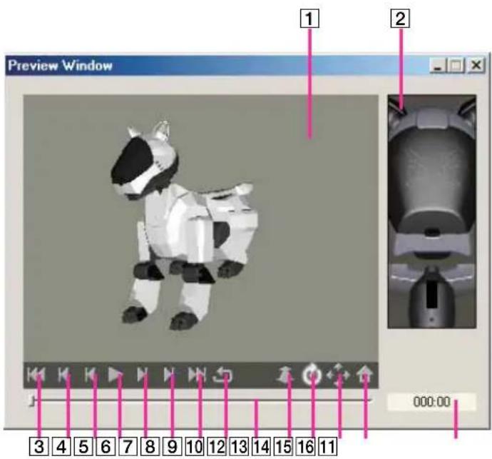
13D view
Displays a 3D view of AIBO.
2 LED display
A preview of the LED data appears.
3 Start pose button
Returns to the start pose.
4 Previous key frame button
Displays the previous key frame.
5 Previous frame button
Displays the previous frame.
6Playback/stop button
Plays back the action. Click again to stop playback.
7 Next frame button
Displays the next frame.
8 Next key frame button
Displays the next key frame.
9 End pose button
Jumps to the end pose.
10 Loop playback button
Plays back repeatedly. Click the playback/stop button to stop playback.
11 Slide bar
Slide to change the current position. Use this bar when AIBO is in stop mode.
12 Zoom button
Zooms in /out the 3D AIBO. Click this button, then drag on the 3D view.
13 Rotate button
Rotates the 3D AIBO. Click this button, then drag on the 3D view.
14Pan button
Pans the 3D AIBO. Click this button, then drag on the 3D view.
15Home position button
Resets the 3D AIBO to the view set in the switch view box.
16 Current time display
Indicates the current position in seconds (unit: 1/100 sec).
Motion Viewer window
Names and functions of window

1 Current time/frame display
Time at current position (unit: 1/100 s) or number of frames (1 frame=0.016 s).
2 Total time/frame display
Total time of motion file (unit: 1/100 s) or number of frames.
3 Time/frame channel
Channel that changes current position. If you click it, the current bar moves to the clicked position.
4 Key frame channel
Channel that displays the key frame of the open motion.
5 Time range change box
Changes the time interval displayed for a channel. Choose from among eight levels in the time/frame display interval for the time/frame channel: 4 frames/8 frames/20 frames/ ^1 / _2 sec/1 sec/2 sec/4 sec/10 sec.
6sec/frame box
Switches display units.
Menus
File
Open
Opens an existing motion file and displays the key frames.
Prints time/frame channel, key frame position, and joint angle movement graph.
Page Setup
Changes printer page settings.
Recent files
Displays up to the last four recently used motion files.
Exit
Closes the Motion Preview window.
Edit
Copy
Copies the selected key frame to the clipboard. Copied key frames can be used in the Action Window.
Select All
Selects all key frames.
Help
User's Guide
Tutorial Guide
AIBO Homepage
About Action Composer
Refer to the section on the Main window (page114).
Glossary
AIBO Master Studio Setup terms
Gateway
Hardware and software device connecting two different systems (a wired LAN and a wireless LAN). It is required if your wireless LAN uses Infrastructure Mode.
IP address
An IP protocol address (a number) used to specify a network and a node on that network.
SSID
Service Set Identifier that sets a unique network ID for individual networks. Access points can only communicate with clients that share the same SSID.
Subnet mask
An IP address is made up of a network address and a host address, and in order to administer more detailed network groups (subnets), host addresses can be divided into network addresses defined by subnets. The subnet mask value indicates the border between a subnet address and a host address.
Topology
The form of a network. A style combining a wired LAN and a wireless LAN is called an Infrastructure topology, while an independent wireless LAN with a wireless adapter for each device is called an ad hoc topology.
WEP key
WEP (Wired Equivalent Privacy) is an encryption method to protect wireless data communications. Receivers need to have the same WEP key as senders to decode the encrypted data.
Wireless LAN
A local area network that uses radio waves and/or infrared to transmit packets through the air instead of using cables.
Quick Behavior Arranger/Behavior Arranger terms
Behavior
An AIBO movement that is made up of several actions. You can create complicated movements, including ones that respond to conditions such as sensor inputs.
Sequential Execution type
A Behavior Program that executes a series of actions one after another.
Stimulus - Drive Execution Type
A Behavior Program that runs actions when sensor, sound, and other events occur.
Subroutine
A small program with a set purpose that is used as needed. When the same process is executed several times, it can be made into an independent program (subroutine) and made available for future use, saving the trouble of writing the same process over again and helping to make programs easier to understand.
Action Composer terms
Action
A unit of information that combines the three elements, motion, sound and LED. In Action Composer, the timing of elements can be adjusted to synchronize with each other.
Element
A component of an action: motion, sound or LED. An action element is a file that contains program data of motion, sound or LED flashing pattern.
Frames
Key frames and subframes in general.
Interpolated frame
A frame (pose) that is generated by AIBO or Action Composer to enable a smooth transition from one key frame to another. Subframes are not displayed in Action Composer.
Key frame
In Action Composer's Action Window or Motion Preview window, a frame that defines a pose in between the start and end poses. AIBO's movements are based on data of key frames and their intervals (time). Key frames can be edited, added or deleted.
LED
Light (LED) emitted by AIBO. AIBO ERS-210 has a total of nine LED's on its face and tail. Duration and brightness (four levels) can be specified for each LED.
Motion
Movement beginning with the start pose and ending with the end pose. Between the start and end poses, AIBO can be made to strike other poses.
Pose
Data specifying the angle of each AIBO joint. AIBO can be made to move in various ways by specifying the angle of each joint.
Start pose/end pose:
Start and end poses are important basic poses. Even when different poses connect motions, by using set poses, AIBO's built-in program enables AIBO to make a smooth transition from one pose to the next.
Start or end poses can be selected in the start or end pose box in the Action Window but start/end poses cannot be edited, added or deleted.
Sound
Sound issued from AIBO's speaker. WAVE and MIDI files can be used. Sound in either format can be edited or a MIDI file created.
Synchronization
To adjust the timing among elements. The timing is adjusted in Action Composer, by using the sound, LED or action markers or by adjusting the start point of a sound file (WAVE/MIDI).
Examples of synchronization are making AIBO perform in time to music and making the LED's flash to accentuate AIBO's movements.
Velocity
Indicates the strength of a note. Velocity originally means “speed”; since the strength of a note played on the piano depends on how fast the key is pressed, the term velocity indicates the strength of a note in MIDI systems.
File organization and files
This section indicates the organization and names of files contained in the AIBO Master Studio folder, the folder where the software is installed.
Common composer
\AIBO Master Studio\Sample
(Behavior Arranger, Action Composer sample, learning materials used in the Tutorial, etc.)
\AIBO Master Studio\REDIST
("Memory Stick" images and files that are copied in AIBO Master Studio Setup.)
Behavior Arranger
\AIBO Master Studio\BA\bitmap
(Bitmap files for setting screen preferences)
\AIBO Master Studio\BA\Library
(Libraries)
Principal files
Behavior file
A file that is edited and created with Behavior Arranger. The behavior file contains AIBO's behavior program, a combination of actions. Extension: *.be
Action library file
A file that is a collection of multiple actions and contains information for each action file. Actions to be used in Behavior Arranger (excluding system actions) are grouped together in an action library file in Action Composer. Extension: *.alb
Action file
A file that contains information on action elements (motion, sound, LED). Extension: *.act
Motion file
A file that contains data on AIBO's movements. Movement data comprises pose data defining the angle of each joint and intervals (time) between each pose. Extension: *.mtn
MIDI sound file
A MIDI file that AIBO plays back. The MIDI sound file is saved in SMF0 format. Extension: *.mid
WAVE sound file
A WAVE file that AIBO plays back. The WAVE sound file is saved in 8-kHz/8-bit/monaural/PCM format. Extension: *.wav
LED file
A file that contains data on the LED flashing pattern. The LED file is saved in SMF0 format. Extension: *.led
Packed action library
This file contains an Action Library, Action files that make up the Action Library, and element files. It is convenient for exchanging complete Action Libraries with other AIBO Master Studio users. Extension: *.plb
Action export file
This file enables actions created in AIBO Master Studio to be made available in AIBO-ware. Extension: *.axf
Index
Accessories 18
Action 12, 73, 135
Configuring elements 72
How to use created actions 50
Play-Action commands 52
Window organization 75
Action box 40
Action box commands 52
Editing commands in a list 40
Action Composer 71
Files that can be created in Action Composer 74
What you can make with Action Composer 72
Action files 73, 74, 138
Exporting action files 100
Action library 73
Action library files 73, 74, 138
Action Window 118
Menu 119
Window names and functions 118
AIBO actions and behaviors 12
AIBO is picked up 16
AIBO Master Studio 13
Program configuration 13
Relationships between programs 15
AIBO state 16
Behavior 12, 135
Creating and Editing Behaviors 34
Keyboard operation 113
Menus 109
Mouse mode 31
Mouse operation 112
Printing behaviors 51
Saving and executing behaviors 38
Window names and functions 108
Behavior arranger 29
Commands 52
Main elements 31
Boxes 32
Action box 32, 40
Branch box 32, 41
Connect Boxes 36
Creating and editing a box 40
Deleting a box 35
Group box 33, 43
Library box 33,44
Moving a box 35
Placing a box 35
Terminal box 33,45
Branch box 41
Connecting branch boxes 36
To edit a command in the list 41
Branch setup dialog box 42
Commands
Action box command 52
Commands that use variables 55
Other commands 56
Play-Action commands 52
To edit a command in the list 40
Composing 89
Copying system files 21
Creating and editing
Behaviors 34
Boxes 40
Files 76
Creating behaviors
Behavior Arranger 34
Quick Behavior Arranger 27
Delete
Disconnecting lines 37
How to delete boxes 35
Disconnecting lines 37
Editing
Editing elements 82
Editing motions 82
Editing poses 85
Editing WAVE files 92
Editing poses 85
Elements 72, 135
Checking elements and actions 97
Editing 82
Element file 74
Synchronizing 96
Execute connection test 24
Executing tests 97
Exporting 99, 100
Action file 100
Action Library file 99
File
Action file 73, 74, 138
Action library file 73, 74, 138
Creating and editing 76
Element file 74
Importing/exporting 99
LED file 73, 74, 93, 138
Main files 138
Sound file 73, 74, 88, 138
File organization and files 137
Gateway 134
Group box 43
Groups
How to use 46
Move/history display 48
How to use created actions 50
Importing 99
Action Library file 99
Install 3, 20
Acrobat Reader 4
AIBO Master Studio 20
Installing Acrobat Reader 4
Interpolated frame 135
IP address 134
Jam conditions 16
Keyboard operation 113
Key frame 72, 135
Adjusting positions 85
LED 73,135
LED file 73, 74, 93, 138
LED Window 128
Menu 129
Window names and functions 128
Library box 33, 44
Main files 138
Main window 114
Menu 115
Window names and functions 114
Marker 96
"Memory Stick"
Copying system files 21
Main specifications 107
"Memory Stick" products that you can use 105
Setting "Memory Stick" drive 20
Menu 109, 115, 119, 124, 127, 129, 133
MIDI Window 123
Menu 124
Window names and functions 123
Motion 72, 135
Editing 82
Motion file 72, 74, 82, 138
Precautions regarding motions 87
Motion Viewer 132
Menu 133
Window names and functions 132
Mouse mode 31
Mouse operation 112
Move
Move a box 35
Move between groups 48
Moving the connecting line 37
Moving the connecting line 37
Page setup 98
Pose 136
Pose Window 122
Window names and functions 122
Preview 97
Preview Window 131
Window names and functions 131
Printing
ActionComposer Printing 98
Print behaviors 51
Program configuration 13
Quick Behavior Arranger 25
Rearranging terminals 49
Relationships Between programs 15
Sequential Execution Type 135
Setting
Setting "Memory Stick" drive 20
Setting up a wireless LAN environment 22
Setup 20
Sound 73, 136
Sound file 73, 74, 88, 138
SSID 134
Start
Behavior Arranger 34
Online manual 4
Quick Behavior Arranger 27
Stimulus - Driven Excution Type 135
Subnet mask 134
Subroutine 135
Synchronization 136
System requirements 19
Terminal box 33
To edit a command in the list 40
Action box 40
Branch box 41
Topology 134
Troubleshooting 102
Uninstall 20
Variables
Commands that use variables 55
Other variables 57
Restrictions on variables 55
Variables common to all models 57
Variables that can be used with AIBO ERS-210/220 64
Variables that can be used with AIBO ERS-310 series 67
Variables using AIBO's joint angles 66, 69
Variables using AIBO's touch sensors 64, 67
Velocity 136
WAVE Window 126
Menu 127
WEP key 134
Window names and functions 126
Window
Organization 75
Print 98
Window names and functions 108, 114, 118, 122, 123, 126, 128, 131, 132
Wireless LAN 134
Executing connection test 24
Functions using a wireless LAN environment 22
Information setup 23
Required devices 22
Setting up a wireless LAN environment 22
Words that can be used for voice recognition 59


- For the customers in U.S.A.
- For the customers in Canada
- For Customers in Europe
- Customer Support
- U.S.A and Canada
- In Europe
- In Australia
- In Hong Kong
- In Singapore
- Sources of information
- User's Guide (this manual)
- Tutorial Guide
- Note
- About the Online Manual
- Installing Acrobat Reader
- To view the Online Manual
- Tip
- Help Menu
- Table of contents
- Chapter 1 Introduction
- Chapter 2 Preparations
- Chapter 3 Quick Behavior Arranger
- Chapter 4 Behavior Arranger
- Using Groups 46
- How to Use Created Actions .... 50
- Printing Behaviors 51
- Command Reference 52
- Chapter 5 Action Composer
- Overview 72
- Creating and Editing Files 76
- Editing Elements.... 82
- Printing windows 98
- Importing/exporting files 99
- Chapter 6 Reference
- Troubleshooting 102
- "Memory Stick" 105
- Behavior Arranger 108
- Action Composer 114
- AIBO Master Studio
- Introduction
- AIBO's "behavior" and "action"
- What is AIBO Master Studio?
- Compatible AIBO Models
- Program Configuration
- AIBO Master Studio Setup
- Quick Behavior Arranger
- Behavior Arranger
- Action Composer
- Compatibility with former versions
- Data compatibility
- "Memory Stick" system file compatibility
- Redistribution of programs
- Relationships Between Programs
- AIBO State
- Normal mode
- Notes
- Falls down
- AIBO is picked up
- Jam condition
- Picked-up condition
- To charge the battery pack
- Chapter 2
- Preparations
- Checking supplied accessories
- ■CD-ROM
- ■Printed material
- System requirements
- Set up
- Installing the software
- Turn on your PC and start Windows.
- Insert the supplied CD-ROM in the CD-ROM drive.
- Uninstalling the software
- Set up "Memory Stick" drive
- Click the Start button in Windows and choose Programs - AIBO Master Studio - AIBO Master Studio Setup.
- Set the "Memory Stick" drive
- Click OK
- Create a “Memory Stick” appropriate for your AIBO model
- Setting up a wireless LAN environment
- Features available with wireless LAN environment
- Required equipment
- For AIBO
- For the PC
- Wireless LAN information setup
- Set up wireless LAN information.
- Click [Export].
- Click [OK] to close the window.
- Execute Connection Test
- Overview
- - Sequential Execution Type
- • Stimulus - Driven Execution Type
- How to use original actions
- How to Create Behaviors
- Click the Start button in Windows and choose Programs - AIBO Master Studio - Quick Behavior Arranger.
- Select your AIBO model name and click Next.
- Select Behavior Program type and click Next.
- Main components of Behavior Arranger
- Mouse modes
- Mouse: normal mode
- Mouse: link mode
- Boxes
- Action box
- Branch box
- Group box
- Terminal box
- Creating and Editing Behaviors
- Start
- Arranging Boxes
- Select a box
- Position a box
- Input content for the box.
- Close properties dialog box
- Allocate as many boxes as you need
- How to move boxes
- How to delete boxes
- Connect Boxes
- Put the mouse in link mode
- Drag from the source box to the destination box
- Connect the rest of the boxes
- How to connect branch boxes
- Connecting group boxes with several output terminals
- Disconnecting boxes
- Moving the connecting line
- Save and Execute Behaviors
- When you use "Memory Stick" drive
- When you use a wireless LAN
- Execute
- Stop
- Emergency Stop
- Write
- Delete
- Check Box
- Trace Box Name
- Step Execute
- If the program execution is complete, click Disconnect.
- Creating and Editing Boxes
- To edit a command in the list
- Condition dialog box
- How to designate a library to a group box
- Using Groups
- Making a group
- When You Create Subroutines
- From the menu, select Group-Create New Group.
- Define the group.
- Close the dialog box.
- Create a behavior program (in the same manner as for a main group).
- From the menu, select File - Close this Window.
- Place a group box, and designate a group name used in the Group combo box of the Group properties dialog box.
- When You Create a group (Subroutine) from a Group Box
- Moving from group to group
- Key operation
- Mouse operation
- Rearranging terminals
- How to Use Created Actions
- Tips
- Printing Behaviors
- Page Setup
- Command Reference
- Action box commands
- Action playback commands (Play-Action)
- CHGPOS.STATR.NORMAL
- CHGPOS.WALK.NORMAL
- CONTACT.FRONT.HEAD
- CONTACT.FRONT.HEADL
- CONTACT.FRONT.HEADR
- CONTACT.RIGHT.TOUCH
- KICK
- LIE
- MOVE\_HEAD
- MOVE.HEAD.FAST
- MOVE.HEAD.NORMAL
- MOVE.HEAD.SLOW
- SIT
- SM ESS.ERROR.ERROR1
- SM ESS.ERROR.ERROR2
- SM ESS.NOTICE.NOTICE1
- SM ESS.NOTICE.NOTICE2
- SM ESS.MODE.CLEAR
- STAND
- STOP\_WALK
- TOUCH
- TRACK\_HEAD
- TURN
- WALK
- Programming precautions
- - Command Completion
- • Overwriting command execution
- Commands that use variables
- Restrictions on variables
- SET
- CLR
- ADD
- SUB
- MUL
- DIV
- MOD
- IOR
- XOR
- RND
- VSAVE
- VLOAD
- VDUMP
- Other commands
- QUIT
- WAIT
- Variables
- Common to all models
- Using the AIBO internal clock
- Year
- Month
- Day
- Hour
- Min
- Sec
- Dow
- Other variables
- Status
- Brightness
- Pink\_Ball
- Pink\_Ball\_H
- Pink\_Ball\_V
- Pink\_Ball\_D
- AU\_AiboSound
- AU\_AiboSound\_ID
- AU\_AiboTone
- AU\_AiboTone\_ID
- AU\_Voice
- AU\_Voice\_ID
- Batt\_Rest
- Batt\_Temp
- Body\_Temp
- Distance
- Words that can be used for voice recognition
- Media link sounds that can be used for sound recognition
- Tonal scales that can be used for sound recognition
- For AIBO ERS-210/220
- Using AIBO touch sensors
- Head\_ON
- Head\_OFF
- Head\_Pat
- Head\_Hit
- Head\_LONG
- Back\_ON
- Back\_OFF
- Back\_LONG
- Jaw\_ON
- Jaw\_OFF
- JAW\_LONG
- RFLeg\_ON
- RFLeg\_OFF
- LFLeg\_ON
- LFLeg\_OFF
- RRLeg\_ON
- RRLeg\_OFF
- LRLeg\_ON
- LRLeg\_OFF
- RTail\_ON (ERS-220 only)
- RTail\_OFF (ERS-220 only)
- RTail\_LONG (ERS-220 only)
- CTail\_ON (ERS-220 only)
- CTail\_OFF (ERS-220 only)
- CTail\_LONG (ERS-220 only)
- LTail\_ON (ERS-220 only)
- LTail\_OFF (ERS-220 only)
- LTail\_LONG (ERS-220 only)
- Using AIBO joint angles
- Head\_Tilt
- Head\_Pan
- Head\_Roll
- Mouth (ERS-210 only)
- RFLeg\_1
- RFLeg\_2
- RFLeg\_3
- LFLeg\_1
- LFLeg\_2
- LFLeg\_3
- RRLeg\_1
- RRLeg\_2
- RRLeg\_3
- LRLeg\_1
- LRLeg\_2
- LRLeg\_3
- For AIBO ERS-310 series
- Tail\_Roll3
- Tail\_RolIR
- Tail\_RoIL
- Tail\_U\_LONG
- Tail\_D\_LONG
- Tail\_R\_LONG
- Tail\_L\_LONG
- Tail\_U\_ON
- Tail\_D\_ON
- Tail\_R\_ON
- Tail\_L\_ON
- Head\_Tilt2
- What you can make with Action Composer
- The three elements of an action
- Motion
- Sound
- LED
- Action
- Action library
- Files that can be created in Action Composer
- Window organization
- Creating and Editing Files
- Creating a library first
- Create new action file
- Save new action file
- Click to select an action file to edit, and create a new element file
- Open action files
- Edit elements
- Save each file
- Creating an action file first
- Creating an element file first
- Motion file
- Sound file
- LED file
- Select your AIBO model.
- Save the LED pattern.
- Create a LED pattern.
- Using action libraries in Behavior Program
- When you use a "Memory Stick" drive
- Editing Elements
- Editing motions
- How to create a new motion
- Editing in the motion channel
- Select the frame you want to edit.
- From the Edit Motion menu, choose the edit command you want.
- Undo
- Redo
- Cut
- Copy
- Overwrite
- Paste
- Delete Frame
- Insert Frame
- Change To Key Frame
- Using existing motion files
- ■ To insert a motion
- ■ To use a key frame
- Adjusting the positions of key frames
- Right-click on a key frame.
- Choose Set Interpolation Frame.
- Enter the number of subframes from the preceding key frame and click OK.
- To make slight adjustments to the key frame position
- Editing Poses
- Changing start and end poses
- Setting up a pose
- Double-click a key frame displayed in the key frame channel.
- Select a body part either from the part list or the AIBO graphic, and set the angle.
- ■ To adjust the viewpoint
- When you've adjusted AIBO to the pose you want, click OK.
- Precautions on motions
- Editing sound
- MIDI file
- ■ Overview of the MIDI Window
- Setting basic items
- Composing sound
- ■ Making sound data
- Select the note you want and place the sound on the score channel.
- Adjust the sound data as required.
- Change the velocity as required.
- ■ Changing sound data
- Click .
- Select the sound data you want from the score channel and make changes.
- To make changes to a sound data
- To delete sound data
- ■ Changing the velocity
- Drag over the velocity line
- ■ Editing the overall sound data
- Select the sound data you want to edit.
- From the Edit menu, choose the edit command you want.
- Insert
- Using existing sound files
- WAVE file
- Compatible WAVE files
- Sound format
- Editing a WAVE file
- Select the segment you want to edit.
- Fade in
- Fade out
- Normalize
- Creating LED data
- Specifying LED data
- Select the brightness level and place LED data on the score channel.
- Adjust the LED data as required.
- Changing LED data
- To make changes to LED data
- To delete LED data
- To change the brightness level
- Editing overall LED data
- Select the LED data you want to edit.
- Synchronizing elements
- Adjusting the starting point of a sound file
- In the Action Window, choose Elements-Set Sound Start Point from the menu.
- Specify the starting time in frames and click OK.
- Using markers
- Adding markers
- In each Window, click the marker channel while pressing the Alt key.
- To erase a marker
- Checking elements and actions
- Previewing on the PC
- Click (Play back button) in the Action Window.
- Executing tests on AIBO
- Select an action or an element
- Transfer an action or element file
- Test run
- Printing windows
- Importing/exporting files
- Import/export of action library files
- Importing
- Exporting
- Using other AIBO-ware action files
- Exporting action files
- Troubleshooting
- "Memory Stick"
- Suitable "Memory Stick" products
- Handling procedures
- About the safety switch
- Precautions on writing to the "Memory Stick"
- Removing the "Memory Stick" from the PC card adapter
- Precautions on use
- Specifications
- Names and functions of the window
- Mouse: Normal mode button
- Group name
- Mouse: Link mode button
- Action box button
- Branch box button
- Group box button
- Terminal box button
- Library box button
- Edit window
- Terminal box (gray)
- Action box
- Branch box
- Group box
- Terminal box (blue)
- History bar
- Menus
- File
- New
- Open
- Save
- Save As
- Recent Files
- Save to Memory Stick
- Wireless LAN Connection
- Exit
- Edit
- Program Comments
- Select All
- View
- Toolbar
- History Bar
- Status Bar
- Scroll Bar
- Resize Edit Range
- Normal View
- Reduced View [50%]
- Reduced View [25%]
- Design View
- Library
- Group
- Help
- Edit window
- Left click
- Left double-click
- Left drag
- Ctrl + left click
- Ctrl + left drag
- Right click
- Others
- Place the mouse pointer over a box in the history bar
- Keyboard operation
- Main window
- Names and functions of window
- New Library
- Open Library
- Save Library
- Save Library As
- Print Preview
- Save Library To Memory Stick
- Upload Library To AIBO
- Import Library
- Export Library
- Properties
- Paste Renamed Selection
- New Action
- Add Action
- Edit Action
- Delete Action
- Rename Action
- Add Comment
- Export Action
- Elements
- New Motion
- Add Motion
- Preview Motion
- Delete Motion
- New MIDI
- Add Sound
- Edit Sound
- Delete Sound
- New LED
- Add LED
- Edit LED
- Delete LED
- Test
- Test Action
- Test Motion
- Test Sound
- Test LED
- Window
- Options
- User's Guide
- AIBO Homepage
- About Action Composer
- Action Window
- Names and function of window
- Current time/frame display
- Total time/frames display
- Current bar
- Key frame
- Action marker (blue)
- LED marker (green)
- Time/frame channel
- Marker channel
- Key frame channel
- Motion channel
- 12Sound channel
- LED channel
- Time interval change box
- 15sec/frame box
- 16Playback button
- End pose box
- Start pose box
- Recent file
- Edit Motion
- Redo (R)
- Insert Motion
- Save Motion As
- Set Sound Start Point
- Preview Window
- AIBO Color
- Pose Window
- MIDI Window
- Action marker (blue)
- LED marker (green)
- Time/frame channel
- Marker channel
- Score channel
- Velocity channel
- 11Sound data
- Select button
- Time interval change box
- 14Sec/frame box
- Notes list
- Time box
- 17Tempo box
- 18Playback button
- Setup
- Input Mode
- Select Mode
- MIDI Device
- WAVE Window
- Name and function of window
- LED Window
- LED data
- LED list
- 12Brightness buttons
- LED diagram
- Brightness 1
- Brightness 2
- Brightness 3
- Brightness 4
- Rotate button
- 14Pan button
- 15Home position button
- Current time display
- Motion Viewer window
- Total time/frame display
- Time/frame channel
- Key frame channel
- Time range change box
- 6sec/frame box
- Glossary
- AIBO Master Studio Setup terms
- Gateway
- IP address
- SSID
- Subnet mask
- Topology
- WEP key
- Wireless LAN
- Quick Behavior Arranger/Behavior Arranger terms
- Behavior
- Sequential Execution type
- Stimulus - Drive Execution Type
- Subroutine
- Action Composer terms
- Element
- Frames
- Interpolated frame
- Key frame
- Pose
- Synchronization
- Velocity
- File organization and files
- Common composer
- Principal files
- Behavior file
- Action library file
- Action file
- MIDI sound file
- WAVE sound file
- Packed action library
- Action export file
- Index
- Accessories 18
- Action 12, 73, 135
- Action box 40
- Action Composer 71
- Action files 73, 74, 138
- Action library 73
- Action Window 118
- AIBO actions and behaviors 12
- AIBO is picked up 16
- AIBO Master Studio 13
- AIBO state 16
- Behavior 12, 135
- Behavior arranger 29
- Boxes 32
- Branch box 41
- Branch setup dialog box 42
- Commands
- Composing 89
- Copying system files 21
- Creating and editing
- Creating behaviors
- Disconnecting lines 37
- Editing
- Editing poses 85
- Elements 72, 135
- Execute connection test 24
- Executing tests 97
- Exporting 99, 100
- File organization and files 137
- Gateway 134
- Group box 43
- Groups
- How to use created actions 50
- Importing 99
- Install 3, 20
- Installing Acrobat Reader 4
- Interpolated frame 135
- IP address 134
- Jam conditions 16
- Keyboard operation 113
- Key frame 72, 135
- LED 73,135
- LED Window 128
- Library box 33, 44
- Main files 138
- Main window 114
- Marker 96
- Menu 109, 115, 119, 124, 127, 129, 133
- MIDI Window 123
- Motion 72, 135
- Motion Viewer 132
- Mouse mode 31
- Mouse operation 112
- Move
- Moving the connecting line 37
- Page setup 98
- Pose 136
- Pose Window 122
- Preview 97
- Preview Window 131
- Printing
- Program configuration 13
- Quick Behavior Arranger 25
- Rearranging terminals 49
- Relationships Between programs 15
- Sequential Execution Type 135
- Setting
- Setup 20
- Sound 73, 136
- SSID 134
- Stimulus - Driven Excution Type 135
- Subnet mask 134
- Subroutine 135
- Synchronization 136
- System requirements 19
- Terminal box 33
- To edit a command in the list 40
- Topology 134
- Uninstall 20
- Velocity 136
- WAVE Window 126
- Wireless LAN 134
- Words that can be used for voice recognition 59
Brand : SONY
Model : ERF-PC03
Category : Unspecified